EP3067542A1 - Secondary air system with venturi - Google Patents
Secondary air system with venturi Download PDFInfo
- Publication number
- EP3067542A1 EP3067542A1 EP16159926.1A EP16159926A EP3067542A1 EP 3067542 A1 EP3067542 A1 EP 3067542A1 EP 16159926 A EP16159926 A EP 16159926A EP 3067542 A1 EP3067542 A1 EP 3067542A1
- Authority
- EP
- European Patent Office
- Prior art keywords
- pressurized air
- gas turbine
- turbine engine
- common
- fluid passages
- Prior art date
- Legal status (The legal status is an assumption and is not a legal conclusion. Google has not performed a legal analysis and makes no representation as to the accuracy of the status listed.)
- Granted
Links
Images



Classifications
-
- F—MECHANICAL ENGINEERING; LIGHTING; HEATING; WEAPONS; BLASTING
- F02—COMBUSTION ENGINES; HOT-GAS OR COMBUSTION-PRODUCT ENGINE PLANTS
- F02C—GAS-TURBINE PLANTS; AIR INTAKES FOR JET-PROPULSION PLANTS; CONTROLLING FUEL SUPPLY IN AIR-BREATHING JET-PROPULSION PLANTS
- F02C6/00—Plural gas-turbine plants; Combinations of gas-turbine plants with other apparatus; Adaptations of gas-turbine plants for special use
- F02C6/04—Gas-turbine plants providing heated or pressurised working fluid for other apparatus, e.g. without mechanical power output
- F02C6/06—Gas-turbine plants providing heated or pressurised working fluid for other apparatus, e.g. without mechanical power output providing compressed gas
- F02C6/08—Gas-turbine plants providing heated or pressurised working fluid for other apparatus, e.g. without mechanical power output providing compressed gas the gas being bled from the gas-turbine compressor
-
- F—MECHANICAL ENGINEERING; LIGHTING; HEATING; WEAPONS; BLASTING
- F01—MACHINES OR ENGINES IN GENERAL; ENGINE PLANTS IN GENERAL; STEAM ENGINES
- F01D—NON-POSITIVE DISPLACEMENT MACHINES OR ENGINES, e.g. STEAM TURBINES
- F01D17/00—Regulating or controlling by varying flow
- F01D17/10—Final actuators
-
- F—MECHANICAL ENGINEERING; LIGHTING; HEATING; WEAPONS; BLASTING
- F01—MACHINES OR ENGINES IN GENERAL; ENGINE PLANTS IN GENERAL; STEAM ENGINES
- F01D—NON-POSITIVE DISPLACEMENT MACHINES OR ENGINES, e.g. STEAM TURBINES
- F01D9/00—Stators
- F01D9/06—Fluid supply conduits to nozzles or the like
- F01D9/065—Fluid supply or removal conduits traversing the working fluid flow, e.g. for lubrication-, cooling-, or sealing fluids
-
- F—MECHANICAL ENGINEERING; LIGHTING; HEATING; WEAPONS; BLASTING
- F02—COMBUSTION ENGINES; HOT-GAS OR COMBUSTION-PRODUCT ENGINE PLANTS
- F02C—GAS-TURBINE PLANTS; AIR INTAKES FOR JET-PROPULSION PLANTS; CONTROLLING FUEL SUPPLY IN AIR-BREATHING JET-PROPULSION PLANTS
- F02C7/00—Features, components parts, details or accessories, not provided for in, or of interest apart form groups F02C1/00 - F02C6/00; Air intakes for jet-propulsion plants
- F02C7/12—Cooling of plants
- F02C7/16—Cooling of plants characterised by cooling medium
- F02C7/18—Cooling of plants characterised by cooling medium the medium being gaseous, e.g. air
-
- F—MECHANICAL ENGINEERING; LIGHTING; HEATING; WEAPONS; BLASTING
- F02—COMBUSTION ENGINES; HOT-GAS OR COMBUSTION-PRODUCT ENGINE PLANTS
- F02K—JET-PROPULSION PLANTS
- F02K3/00—Plants including a gas turbine driving a compressor or a ducted fan
-
- F—MECHANICAL ENGINEERING; LIGHTING; HEATING; WEAPONS; BLASTING
- F02—COMBUSTION ENGINES; HOT-GAS OR COMBUSTION-PRODUCT ENGINE PLANTS
- F02K—JET-PROPULSION PLANTS
- F02K3/00—Plants including a gas turbine driving a compressor or a ducted fan
- F02K3/02—Plants including a gas turbine driving a compressor or a ducted fan in which part of the working fluid by-passes the turbine and combustion chamber
- F02K3/04—Plants including a gas turbine driving a compressor or a ducted fan in which part of the working fluid by-passes the turbine and combustion chamber the plant including ducted fans, i.e. fans with high volume, low pressure outputs, for augmenting the jet thrust, e.g. of double-flow type
- F02K3/06—Plants including a gas turbine driving a compressor or a ducted fan in which part of the working fluid by-passes the turbine and combustion chamber the plant including ducted fans, i.e. fans with high volume, low pressure outputs, for augmenting the jet thrust, e.g. of double-flow type with front fan
-
- F—MECHANICAL ENGINEERING; LIGHTING; HEATING; WEAPONS; BLASTING
- F05—INDEXING SCHEMES RELATING TO ENGINES OR PUMPS IN VARIOUS SUBCLASSES OF CLASSES F01-F04
- F05D—INDEXING SCHEME FOR ASPECTS RELATING TO NON-POSITIVE-DISPLACEMENT MACHINES OR ENGINES, GAS-TURBINES OR JET-PROPULSION PLANTS
- F05D2260/00—Function
- F05D2260/60—Fluid transfer
-
- F—MECHANICAL ENGINEERING; LIGHTING; HEATING; WEAPONS; BLASTING
- F05—INDEXING SCHEMES RELATING TO ENGINES OR PUMPS IN VARIOUS SUBCLASSES OF CLASSES F01-F04
- F05D—INDEXING SCHEME FOR ASPECTS RELATING TO NON-POSITIVE-DISPLACEMENT MACHINES OR ENGINES, GAS-TURBINES OR JET-PROPULSION PLANTS
- F05D2260/00—Function
- F05D2260/60—Fluid transfer
- F05D2260/601—Fluid transfer using an ejector or a jet pump
Definitions
- the application relates generally to gas turbine engines and, more particularly, to secondary air systems for such engines.
- Secondary air systems in gas turbine engines use pressurized air bled from the compressor for many purposes, including cooling and pressuring seals to reduce the risk of leaks.
- the pressurized air bled from any location within the compressor has a pressure which typically varies throughout the range of operation of the engine.
- the pressure of the bleed air of the compressor increases when the engine is operated at a full power level in contrast to an idling condition.
- Such systems thus necessitate a valve to switch between the two pressure sources, and control logic to control the valve to connect to the correct source.
- a gas turbine engine comprising: a compressor providing a source of pressurized air; a secondary air system including a plurality of interconnected fluid passages defining at least one flow path between the source of pressurized air and a common outlet communicating with an environment of the gas turbine engine, some of the plurality of fluid passages communicating with components of the gas turbine engine for delivery of the pressurized air thereto, the plurality of fluid passages includes a common fluid passage through which all circulation of the pressurized air to the common outlet passes, the common fluid passage including a venturi configured for controlling a flow of the pressurized air from the source of pressurized air to the common outlet through the plurality of fluid passages.
- a gas turbine engine comprising: a compressor defining a source of pressurized air; a secondary air system including: an inlet passage communicating with the source of pressurized air; an outlet passage communicating with an environment of the gas turbine engine; and a plurality of interconnected additional passages communicating between the inlet passage and the outlet passage; wherein one of the inlet and outlet passages has a section of constricted internal cross-section configured for controlling a flow of the pressurized air therethrough.
- the section of constricted internal cross-section may define a venturi.
- the venturi may be located in the inlet passage or in the outlet passage.
- the compressor may include a plurality of rotors having blades rotatable in an annular flow path, the source of pressurized air being defined by a plenum in fluid communication with the annular flow path of the compressor.
- the plurality of rotors may include at least one low pressure rotor drivingly engaged to a low pressure shaft and at least one high pressure rotor downstream of the at least one low pressure rotor and drivingly engaged to a high pressure shaft, the low and high pressure shaft being independently rotatable in a concentric manner, the plenum communicating with the annular flow path immediately upstream of a most downstream one of the at least one high pressure rotors.
- a method of pressurizing a secondary air system in a gas turbine engine comprising: circulating pressurized air from a source of pressurized air to a plurality of interconnected fluid passages; circulating the pressurized air through the fluid passages to deliver the pressurized air to a plurality of components of the gas turbine engine; exhausting the pressurized air from the fluid passages to an environment of the gas turbine engine through an outlet located downstream of the plurality of components, wherein all the pressurized air exhausted through the outlet circulates through a common one of the fluid passages before being exhausted; at low power, accelerating a flow of the pressurized air through the common one of the fluid passages, the flow being accelerated by circulation through a venturi defined in the common one of the fluid passages; and at high power, choking the flow of the pressurized air through the venturi, wherein accelerating and choking the flow controls a pressure drop of the pressurized air throughout the fluid passages.
- Fig. 1 illustrates a gas turbine engine 10 of a type preferably provided for use in subsonic flight, generally comprising in serial flow communication a fan 12 through which ambient air is propelled, a compressor section 14 for pressurizing the air, a combustor 16 in which the compressed air is mixed with fuel and ignited for generating an annular stream of hot combustion gases, and a turbine section 18 for extracting energy from the combustion gases.
- the compressor section 14 includes a high pressure compressor 14H, with one or more compressor rotor(s) drivingly engaged to a high pressure shaft 20 of the engine 10; the high pressure shaft 20 is driven by the one or more rotor(s) of a high pressure turbine 18H forming part of the turbine section 18.
- a low pressure shaft 22 extends within and concentric with the high pressure shaft 20, and is engaged at one end to the fan 12, and at the other end to one or more rotor(s) of a low pressure turbine 18L of the turbine section 18.
- the compressor section 14 may also include one or more low compressor rotor(s) engaged to the low pressure shaft 22.
- the high pressure and low pressure shafts 20, 22 rotate independently from each other.
- a secondary air system 30 delivers pressurized air to a plurality of components 32 of the gas turbine engine 10.
- the pressurized air is delivered for cooling purposes: the components receiving the pressurized air may include, for example, rotors, blades or vanes of the turbine section 18 or of the compressor section 14, shrouds, seals, etc.
- the pressurized air is delivered to apply a back pressure to the component, for example to balance a fluid pressure on the other side of the component: the components receiving the pressurized air may include, for example, seals such as bearing cavity seals and other oil cavity seals. It is understood that the pressurized air may perform more than one function on a same component.
- the secondary air system 30 generally includes a plurality of interconnected fluid passages.
- the fluid passages include a common inlet passage 34, a common outlet passage 36, and additional passages 38, 40, some of which "branch out” from others, for example to deliver the pressurized air to the various gas turbine engine components 32.
- the fluid passages 34, 36, 38, 40 are all in communication, either directly or through one another, with a common source 50 of pressurized air. In the embodiment shown, the communication with the common source 50 is provided through the common inlet passage 34.
- the source 50 of pressurized air is defined in the compressor section 14.
- the source 50 of pressurized air is a plenum defined around the annular gas path 24 of the engine receiving the blades of the compressor rotors.
- the plenum 50 communicates with the annular gas path 24 through one or more ports 26 defined through the outer wall of the gas path 24 of the high pressure compressor 14H.
- a centrifugal rotor 52 is provided at the downstream end of the high pressure compressor 14H, and the port(s) 26 are provided between the centrifugal rotor 52 and the axial compressor rotor 54 immediately upstream of it.
- the source 50 of pressurized air could bleed air from a different location of the compressor section 14, depending on the pressure requirements of the secondary air system 30 on the pressure profile within the compressor section 14, and on the engine configuration, including, but not limited to, any stage along the high pressure compressor 14H, upstream of any rotor/at the exit of any stator of the compressor section 14, along the impeller shroud of the centrifugal rotor 52, at the tip of the blades of the centrifugal rotor 52, and through the inner gas path wall.
- the fluid passages 34, 36, 38, 40 are also all in communication, either directly or through one another, with a common outlet 56.
- the communication with the common outlet 56 is provided through the common outlet passage 36.
- the outlet 56 communicates with an environment of the gas turbine engine 10, for example by discharging into an unpressurized plenum which is open to atmosphere.
- the fluid passages 34, 36, 38, 40 thus define at least one flow path between the common source 50 of pressurized air and the common outlet 56. All of the flow path(s) pass through at least one common fluid passage - all the pressurized air flowing from the common source to the common outlet through the fluid passages thus passes through this/these common fluid passage(s).
- multiple common fluid passages are provided, including the common inlet passage 34, the common outlet passage 36, and common intermediary passages 38. Other configurations are also possible.
- one of the common passages 34, 36, 38 includes a section of constricted internal cross-section forming a venturi 60, such that all of the pressurized air reaching the common outlet 56 has to circulate through this constricted section before being exhausted.
- the venturi 60 is schematically indicated in full lines as being defined in the inlet passage 34, and multiple, non-exhaustive and alternate possible locations for the venturi 60' are schematically shown in dotted lines: in the common outlet passage 36, and in the common intermediary passages 38.
- the venturi 60 is configured to limit the flow through the fluid passages 34, 36, 38, 40 at high power but not at low power. Accordingly, it defines a control point for the flow of pressurized air through the fluid passages 34, 36, 38, 40.
- the flow 80 through the venturi 60 is the same at high power than the flow 82 through an equivalent control orifice (e.g. cylindrical orifice).
- the venturi 60 opposes less resistance, and accordingly the flow 80 through the venturi 60 is higher than the flow 82 through the equivalent control orifice.
- this increased flow through the venturi 60 at low power allows for sufficient flow to be provided to the various engine components 32 receiving pressurized air from the secondary air system 30.
- venturi 60 accelerates the flow through its smaller section 76, and chokes the flow when its local speed approaches the sonic range.
- the venturi 60 thus flows freely at low power and limits the flow at high power, thus allowing a more constant flow through the fluid passages throughout variations of power of the engine while using a same source of pressurized air throughout these variations of power.
- low power designates the power demand on the engine during ground idle and taxi
- high power designates the power demand on the engine during take-off, climb and cruise.
- low power corresponds to a total pressure ratio (Pt u/s / Pt d/s ) of less than 1.1, and high power to a total pressure ratio of at least 2; other values are also possible, including, but not limited to, low power corresponding to a total pressure ratio of around 1, and/or high power corresponding to a total pressure ratio of at least 3.
- a particular embodiment of the secondary air system 30 is shown, where the venturi 60 is provided in the outlet passage 36 ( Fig. 4 ); a possible alternate location is indicated at 60' in Fig. 3 , as part of the inlet passage 34.
- the common inlet passage 34 extends through a strut 58 passing through the gas path 24 of the gas turbine engine 10, between the low pressure compressor 14L and the high pressure compressor 14H.
- the common inlet passage 34 may circulate through a heat exchanger or other cooling system to reduce the temperature of the pressurized air bled from the high pressure compressor 14H.
- the fluid passages includes a passage 40a extending generally axially from the common inlet passage 34 toward the front of the engine 10 (toward the fan 12), and delivering the pressurized air against the seals 32a of the oil cavity containing the end bearing 64a supporting the end of the low pressure shaft 22.
- the fluid passages also include another passage 38b extending generally axially from the common inlet passage 34 toward the rear of the engine 10. From this passage 38b stems a passage 40c directed axially forwardly and delivering the pressurized air against a seal 32c of the oil cavity containing the end bearing 64c supporting the end of the high pressure shaft 20 and another bearing 64e supporting the low pressure shaft 22; a passage 38d directed radially inwardly to communicate with a passage 38e defined between the high and low pressure shafts 20, 22; and a passage 40f directed axially rearwardly and defined between the high pressure shaft 20 and the bores 66 of the rotors of the high pressure compressor 14H.
- the passage 38e between the two shafts 20, 22 delivers the pressurized air against other seals 32e of the oil cavity containing the end bearing 64c supporting the end of the high pressure shaft 20 and the bearing 64e supporting the low pressure shaft 22.
- the passage 40f defined between the high pressure shaft 20 and the bores 66 of the rotors of the high pressure compressor 14H communicates with other passages 40g delivering the pressurized air to the blades and vanes of the high pressure compressor 14H. Other passages may also be provided.
- the passage 38e between the two shafts 20, 22 is defined along the length of the high pressure shaft 20, and at the end of the high pressure shaft 20 communicates with the outlet passage 36 defined at the center of the hollow low pressure shaft 22, for example through one or more holes 68 defined through the annular wall of the low pressure shaft 22.
- the low pressure shaft 22 is engaged to surrounding components 70, such as an arm connected to the disks of the low pressure turbine blades, by an end bolt 72 applying a preloading to the assembly.
- the bolt 72 is received at the end of the low pressure shaft 22, within the outlet passage 36 defined through the low pressure shaft 22.
- the bolt 72 is hollow, and its outer surface is in contact with the inner surface of the shaft 22; accordingly, the air circulating through the outlet passage 36 must circulate through the hollow bolt 72 to reach the outlet 56, which is defined downstream of the bolt 72.
- the central opening of the bolt 72 is configured to define the venturi 60.
- the inner wall defining the central opening of the bolt 72 has, from its upstream end to its downstream end, a first angled section 74 defining a tapering cross-section becoming progressively smaller, then an axial section 76 defining a constant cross-section corresponding to the smallest cross-section of the central opening, then a second angled section 78 defining a tapering cross-section becoming progressively larger.
- the cone angle formed by the walls in each angled section 74, 76 may be different from one another.
- the walls in the second angled section 78 have a steeper slope that the walls in the first angled section 74.
- venturi 60 can alternately be provided by the walls of one of the common passages in integral, monolithic form, instead of being provided by an element inserted into the passage.
- the secondary air system 30 thus circulates the pressurized air from the common source 50 through the fluid passages 34, 36, 38, 40 to deliver the pressurized air to the components 32 of the gas turbine engine 10.
- the pressurized air is exhausted from the fluid passages 34, 36, 38, 40 to the environment through the common outlet 56 located downstream of the components 32, and all the pressurized air exhausted through the outlet 56 circulates through at least one common fluid passage 34, 36, 38 before being exhausted.
- the flow is restricted in the common fluid passage 34, 36, 38 to control the pressure drop of the pressurized air throughout the fluid passages 34, 36, 38, 40, by circulation through the venturi 60.
Landscapes
- Engineering & Computer Science (AREA)
- Mechanical Engineering (AREA)
- General Engineering & Computer Science (AREA)
- Chemical & Material Sciences (AREA)
- Combustion & Propulsion (AREA)
- Physics & Mathematics (AREA)
- Fluid Mechanics (AREA)
- Structures Of Non-Positive Displacement Pumps (AREA)
Abstract
Description
- The application relates generally to gas turbine engines and, more particularly, to secondary air systems for such engines.
- Secondary air systems in gas turbine engines use pressurized air bled from the compressor for many purposes, including cooling and pressuring seals to reduce the risk of leaks. However, the pressurized air bled from any location within the compressor has a pressure which typically varies throughout the range of operation of the engine. For example, the pressure of the bleed air of the compressor increases when the engine is operated at a full power level in contrast to an idling condition. Accordingly, it is known to have a secondary air system using bleed air from a first location in the compressor at high power, and from a second location downstream of the first location in the compressor at low power, for example such as to ensure sufficient pressure and airflow within the system throughout the range of engine power. Such systems thus necessitate a valve to switch between the two pressure sources, and control logic to control the valve to connect to the correct source.
- In one aspect, there is provided a gas turbine engine comprising: a compressor providing a source of pressurized air; a secondary air system including a plurality of interconnected fluid passages defining at least one flow path between the source of pressurized air and a common outlet communicating with an environment of the gas turbine engine, some of the plurality of fluid passages communicating with components of the gas turbine engine for delivery of the pressurized air thereto, the plurality of fluid passages includes a common fluid passage through which all circulation of the pressurized air to the common outlet passes, the common fluid passage including a venturi configured for controlling a flow of the pressurized air from the source of pressurized air to the common outlet through the plurality of fluid passages.
- In another aspect, there is provided a gas turbine engine comprising: a compressor defining a source of pressurized air; a secondary air system including: an inlet passage communicating with the source of pressurized air; an outlet passage communicating with an environment of the gas turbine engine; and a plurality of interconnected additional passages communicating between the inlet passage and the outlet passage; wherein one of the inlet and outlet passages has a section of constricted internal cross-section configured for controlling a flow of the pressurized air therethrough. The section of constricted internal cross-section may define a venturi. The venturi may be located in the inlet passage or in the outlet passage. The compressor may include a plurality of rotors having blades rotatable in an annular flow path, the source of pressurized air being defined by a plenum in fluid communication with the annular flow path of the compressor. The plurality of rotors may include at least one low pressure rotor drivingly engaged to a low pressure shaft and at least one high pressure rotor downstream of the at least one low pressure rotor and drivingly engaged to a high pressure shaft, the low and high pressure shaft being independently rotatable in a concentric manner, the plenum communicating with the annular flow path immediately upstream of a most downstream one of the at least one high pressure rotors.
- In a further aspect, there is provided a method of pressurizing a secondary air system in a gas turbine engine, the method comprising: circulating pressurized air from a source of pressurized air to a plurality of interconnected fluid passages; circulating the pressurized air through the fluid passages to deliver the pressurized air to a plurality of components of the gas turbine engine; exhausting the pressurized air from the fluid passages to an environment of the gas turbine engine through an outlet located downstream of the plurality of components, wherein all the pressurized air exhausted through the outlet circulates through a common one of the fluid passages before being exhausted; at low power, accelerating a flow of the pressurized air through the common one of the fluid passages, the flow being accelerated by circulation through a venturi defined in the common one of the fluid passages; and at high power, choking the flow of the pressurized air through the venturi, wherein accelerating and choking the flow controls a pressure drop of the pressurized air throughout the fluid passages.
- Reference is now made to the accompanying figures in which:
-
Fig. 1 is a schematic cross-sectional view of a gas turbine engine; -
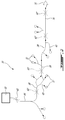
Fig. 2 is a schematic view of a secondary air system which may be used on a gas turbine engine, in accordance with a particular embodiment; -
Fig. 3 is a schematic cross-sectional view of a part of a secondary air system in accordance with a particular embodiment; -
Fig. 4 is a schematic cross-sectional view of another part of the secondary air system ofFig. 3 ; and -
Fig. 5 is a comparative graph of normalized flow through a venturi and through a control orifice. -
Fig. 1 illustrates agas turbine engine 10 of a type preferably provided for use in subsonic flight, generally comprising in serial flow communication afan 12 through which ambient air is propelled, acompressor section 14 for pressurizing the air, acombustor 16 in which the compressed air is mixed with fuel and ignited for generating an annular stream of hot combustion gases, and aturbine section 18 for extracting energy from the combustion gases. Thecompressor section 14 includes ahigh pressure compressor 14H, with one or more compressor rotor(s) drivingly engaged to ahigh pressure shaft 20 of theengine 10; thehigh pressure shaft 20 is driven by the one or more rotor(s) of ahigh pressure turbine 18H forming part of theturbine section 18. Alow pressure shaft 22 extends within and concentric with thehigh pressure shaft 20, and is engaged at one end to thefan 12, and at the other end to one or more rotor(s) of alow pressure turbine 18L of theturbine section 18. Although not shown, thecompressor section 14 may also include one or more low compressor rotor(s) engaged to thelow pressure shaft 22. The high pressure andlow pressure shafts - Referring to
Fig. 2 , asecondary air system 30 delivers pressurized air to a plurality ofcomponents 32 of thegas turbine engine 10. In some instances, the pressurized air is delivered for cooling purposes: the components receiving the pressurized air may include, for example, rotors, blades or vanes of theturbine section 18 or of thecompressor section 14, shrouds, seals, etc. In other instances, the pressurized air is delivered to apply a back pressure to the component, for example to balance a fluid pressure on the other side of the component: the components receiving the pressurized air may include, for example, seals such as bearing cavity seals and other oil cavity seals. It is understood that the pressurized air may perform more than one function on a same component. - The
secondary air system 30 generally includes a plurality of interconnected fluid passages. In the embodiment shown, the fluid passages include acommon inlet passage 34, acommon outlet passage 36, andadditional passages turbine engine components 32. Thefluid passages common source 50 of pressurized air. In the embodiment shown, the communication with thecommon source 50 is provided through thecommon inlet passage 34. - The
source 50 of pressurized air is defined in thecompressor section 14. In a particular embodiment, and with reference toFig. 1 , thesource 50 of pressurized air is a plenum defined around theannular gas path 24 of the engine receiving the blades of the compressor rotors. Theplenum 50 communicates with theannular gas path 24 through one ormore ports 26 defined through the outer wall of thegas path 24 of thehigh pressure compressor 14H. In the embodiment shown, acentrifugal rotor 52 is provided at the downstream end of thehigh pressure compressor 14H, and the port(s) 26 are provided between thecentrifugal rotor 52 and theaxial compressor rotor 54 immediately upstream of it. It is however understood that in other embodiments, thesource 50 of pressurized air could bleed air from a different location of thecompressor section 14, depending on the pressure requirements of thesecondary air system 30 on the pressure profile within thecompressor section 14, and on the engine configuration, including, but not limited to, any stage along thehigh pressure compressor 14H, upstream of any rotor/at the exit of any stator of thecompressor section 14, along the impeller shroud of thecentrifugal rotor 52, at the tip of the blades of thecentrifugal rotor 52, and through the inner gas path wall. - Referring back to
Fig. 2 , thefluid passages common outlet 56. In the embodiment shown, the communication with thecommon outlet 56 is provided through thecommon outlet passage 36. Theoutlet 56 communicates with an environment of thegas turbine engine 10, for example by discharging into an unpressurized plenum which is open to atmosphere. - The
fluid passages common source 50 of pressurized air and thecommon outlet 56. All of the flow path(s) pass through at least one common fluid passage - all the pressurized air flowing from the common source to the common outlet through the fluid passages thus passes through this/these common fluid passage(s). In the embodiment shown, multiple common fluid passages are provided, including thecommon inlet passage 34, thecommon outlet passage 36, and commonintermediary passages 38. Other configurations are also possible. - In order to control the flow of the pressurized air from the
common source 50 to thecommon outlet 56, one of thecommon passages venturi 60, such that all of the pressurized air reaching thecommon outlet 56 has to circulate through this constricted section before being exhausted. InFig. 2 , theventuri 60 is schematically indicated in full lines as being defined in theinlet passage 34, and multiple, non-exhaustive and alternate possible locations for the venturi 60' are schematically shown in dotted lines: in thecommon outlet passage 36, and in the commonintermediary passages 38. Theventuri 60 is configured to limit the flow through thefluid passages fluid passages - Referring to
Fig. 5 showing the flow as a function of the total pressure ratio (Ptu/s / Ptd/s), where Ptu/s is the total pressure upstream of the system and Ptd/s is the total pressure downstream of the system. In a particular embodiment, theflow 80 through theventuri 60 is the same at high power than theflow 82 through an equivalent control orifice (e.g. cylindrical orifice). At low power, theventuri 60 opposes less resistance, and accordingly theflow 80 through theventuri 60 is higher than theflow 82 through the equivalent control orifice. In a particular embodiment, this increased flow through theventuri 60 at low power allows for sufficient flow to be provided to thevarious engine components 32 receiving pressurized air from thesecondary air system 30. At higher power, theventuri 60 accelerates the flow through itssmaller section 76, and chokes the flow when its local speed approaches the sonic range. Theventuri 60 thus flows freely at low power and limits the flow at high power, thus allowing a more constant flow through the fluid passages throughout variations of power of the engine while using a same source of pressurized air throughout these variations of power. - In a particular embodiment, "low power" designates the power demand on the engine during ground idle and taxi, while "high power" designates the power demand on the engine during take-off, climb and cruise. In a particular embodiment, low power corresponds to a total pressure ratio (Ptu/s / Ptd/s) of less than 1.1, and high power to a total pressure ratio of at least 2; other values are also possible, including, but not limited to, low power corresponding to a total pressure ratio of around 1, and/or high power corresponding to a total pressure ratio of at least 3.
- Referring to
Figs. 3-4 , a particular embodiment of thesecondary air system 30 is shown, where theventuri 60 is provided in the outlet passage 36 (Fig. 4 ); a possible alternate location is indicated at 60' inFig. 3 , as part of theinlet passage 34. - Referring to
Fig. 3 , in this embodiment, thecommon inlet passage 34 extends through astrut 58 passing through thegas path 24 of thegas turbine engine 10, between thelow pressure compressor 14L and thehigh pressure compressor 14H. Although not shown, thecommon inlet passage 34 may circulate through a heat exchanger or other cooling system to reduce the temperature of the pressurized air bled from thehigh pressure compressor 14H. The fluid passages includes apassage 40a extending generally axially from thecommon inlet passage 34 toward the front of the engine 10 (toward the fan 12), and delivering the pressurized air against theseals 32a of the oil cavity containing the end bearing 64a supporting the end of thelow pressure shaft 22. - The fluid passages also include another
passage 38b extending generally axially from thecommon inlet passage 34 toward the rear of theengine 10. From thispassage 38b stems apassage 40c directed axially forwardly and delivering the pressurized air against aseal 32c of the oil cavity containing the end bearing 64c supporting the end of thehigh pressure shaft 20 and anotherbearing 64e supporting thelow pressure shaft 22; apassage 38d directed radially inwardly to communicate with apassage 38e defined between the high andlow pressure shafts passage 40f directed axially rearwardly and defined between thehigh pressure shaft 20 and thebores 66 of the rotors of thehigh pressure compressor 14H. - The
passage 38e between the twoshafts other seals 32e of the oil cavity containing the end bearing 64c supporting the end of thehigh pressure shaft 20 and thebearing 64e supporting thelow pressure shaft 22. Thepassage 40f defined between thehigh pressure shaft 20 and thebores 66 of the rotors of thehigh pressure compressor 14H communicates withother passages 40g delivering the pressurized air to the blades and vanes of thehigh pressure compressor 14H. Other passages may also be provided. - Referring to
Fig. 4 , it can be seen that thepassage 38e between the twoshafts high pressure shaft 20, and at the end of thehigh pressure shaft 20 communicates with theoutlet passage 36 defined at the center of the hollowlow pressure shaft 22, for example through one ormore holes 68 defined through the annular wall of thelow pressure shaft 22. - In this particular embodiment, the
low pressure shaft 22 is engaged to surroundingcomponents 70, such as an arm connected to the disks of the low pressure turbine blades, by anend bolt 72 applying a preloading to the assembly. Thebolt 72 is received at the end of thelow pressure shaft 22, within theoutlet passage 36 defined through thelow pressure shaft 22. Thebolt 72 is hollow, and its outer surface is in contact with the inner surface of theshaft 22; accordingly, the air circulating through theoutlet passage 36 must circulate through thehollow bolt 72 to reach theoutlet 56, which is defined downstream of thebolt 72. The central opening of thebolt 72 is configured to define theventuri 60. - Accordingly, it can be seen that the inner wall defining the central opening of the
bolt 72 has, from its upstream end to its downstream end, a firstangled section 74 defining a tapering cross-section becoming progressively smaller, then anaxial section 76 defining a constant cross-section corresponding to the smallest cross-section of the central opening, then a secondangled section 78 defining a tapering cross-section becoming progressively larger. It is understood that the cone angle formed by the walls in eachangled section angled section 78 have a steeper slope that the walls in the firstangled section 74. - It is understood that the
venturi 60 can alternately be provided by the walls of one of the common passages in integral, monolithic form, instead of being provided by an element inserted into the passage. - In use, the
secondary air system 30 thus circulates the pressurized air from thecommon source 50 through thefluid passages components 32 of thegas turbine engine 10. The pressurized air is exhausted from thefluid passages common outlet 56 located downstream of thecomponents 32, and all the pressurized air exhausted through theoutlet 56 circulates through at least onecommon fluid passage common fluid passage fluid passages venturi 60. - The above description is meant to be exemplary only, and one skilled in the art will recognize that changes may be made to the embodiments described without departing from the scope of the invention disclosed. Modifications which fall within the scope of the present invention will be apparent to those skilled in the art, in light of a review of this disclosure, and such modifications are intended to fall within the appended claims.
Claims (15)
- A gas turbine engine (10) comprising:a compressor (14) providing a source of pressurized air (50);a secondary air system (30) including a plurality of interconnected fluid passages (34,36,38,40) defining at least one flow path between the source of pressurized air (50) and a common outlet (56) communicating with an environment of the gas turbine engine, some of the plurality of fluid passages (34,36,38,40) communicating with components (32) of the gas turbine engine for delivery of the pressurized air thereto, the plurality of fluid passages including a common fluid passage (34) through which all circulation of the pressurized air to the common outlet (56) passes, the common fluid passage (34) including a venturi (60) configured for controlling a flow of the pressurized air (50) from the source of pressurized air to the common outlet (56) through the plurality of fluid passages (34,36,38,40).
- The engine as defined in claim 1, wherein:the plurality of interconnected fluid passages include:an inlet passage (34) communicating with the source of pressurized air (50);an outlet passage (36) communicating with the environment of the gas turbine engine; anda plurality of interconnected additional passages (38,40) communicating between the inlet passage (34) and the outlet passage (36);wherein one of the inlet and outlet passages (34,36) is the common fluid passage including the venturi (60) and has a section of constricted internal cross-section (76) configured for controlling the flow of the pressurized air therethrough.
- The gas turbine engine as defined in claim 1 or 2, wherein the components (32) of the gas turbine engine communicating with the fluid passages include one or more of oil cavity seals, rotors, blades and vanes.
- The gas turbine engine as defined in any one of the preceding claims, wherein the venturi (60) is located downstream with respect to the fluid passages communicating with the components (32) of the gas turbine engine.
- The gas turbine engine as defined in any one of the preceding claims, wherein the common fluid passage including the venturi (60) is an inlet passage (34) providing the communication between the source of pressurized air (50) and the other fluid passages.
- The gas turbine engine as defined in any one of claims 1 to 4, wherein the common fluid passage including the venturi (60) is an outlet passage (36) providing the communication between the common outlet (56) and the other fluid passages (34,38,40).
- The gas turbine engine as defined in any one of claims 1 to 4, wherein the common fluid passage is defined through a low pressure shaft (22) of the gas turbine engine, the venturi (60) being defined at one end of the low pressure shaft (22), the communication between the common outlet (56) and the other fluid passages being provided through the low pressure shaft (22).
- The gas turbine engine as defined in claim 2, wherein the outlet passage is defined through a low pressure shaft (22) of the gas turbine engine, the venturi (60) being defined by a central opening of a hollow bolt (72) received within the outlet passage (36) at one end of the low pressure shaft (22).
- The gas turbine engine as defined in any one of the preceding claims, wherein the compressor (14) includes a plurality of rotors having blades rotatable in an annular gas path (24), the source of pressurized air (50) being defined by a plenum (50) in fluid communication with the annular gas path (24) of the compressor.
- The gas turbine engine as defined in claim 9, wherein the plurality of rotors includes at least one low pressure rotor drivingly engaged to a low pressure shaft (22) and at least one high pressure rotor downstream of the at least one low pressure rotor and drivingly engaged to a high pressure shaft (20), the low and high pressure shafts (22,20) being independently rotatable in a concentric manner, the plenum communicating with the annular gas path (24) in proximity of one of the at least one high pressure rotors.
- A method of pressurizing a secondary air system (30) in a gas turbine engine (10), the method comprising:circulating pressurized air (50) from a source of pressurized air to a plurality of interconnected fluid passages (34,36,38,40);circulating the pressurized air through the fluid passages (34,36,38,40) to deliver the pressurized air to a plurality of components (32) of the gas turbine engine (20);exhausting the pressurized air from the fluid passages (34,36,38,40) to an environment of the gas turbine engine through an outlet (56) located downstream of the plurality of components (32), wherein all the pressurized air exhausted through the outlet (56) circulates through a common one of the fluid passages (34,36,38,40) before being exhausted;at low power, accelerating a flow of the pressurized air through the common one of the fluid passages, the flow being accelerated by circulation through a venturi (60) defined in the common one of the fluid passages; andat high power, choking the flow of the pressurized air through the venturi (60), wherein accelerating and choking the flow controls a pressure drop of the pressurized air throughout the fluid passages (34,36,38,40).
- The method as defined in claim 11, wherein accelerating and choking the flow of the pressurized air is performed upstream of delivering the pressurized air to the plurality of components (32).
- The method as defined in claim 11, wherein accelerating and choking the flow of the pressurized air is performed downstream of delivering the pressurized air to the plurality of components (32).
- The method as defined in any one of claims 11 to 13, wherein accelerating and choking the flow of the pressurized air is performed in a low pressure shaft (22) of the gas turbine engine.
- The method as defined in any one of claims 11 to 14, wherein circulating the pressurized air from the source includes circulating the pressurized air from a plenum (50) communicating with a gas path (24) of the gas turbine engine (20) between stages of a high pressure compressor (14H) thereof.
Applications Claiming Priority (1)
| Application Number | Priority Date | Filing Date | Title |
|---|---|---|---|
| US14/644,503 US10100730B2 (en) | 2015-03-11 | 2015-03-11 | Secondary air system with venturi |
Publications (2)
| Publication Number | Publication Date |
|---|---|
| EP3067542A1 true EP3067542A1 (en) | 2016-09-14 |
| EP3067542B1 EP3067542B1 (en) | 2021-10-27 |
Family
ID=55527421
Family Applications (1)
| Application Number | Title | Priority Date | Filing Date |
|---|---|---|---|
| EP16159926.1A Active EP3067542B1 (en) | 2015-03-11 | 2016-03-11 | Secondary air system with venturi |
Country Status (3)
| Country | Link |
|---|---|
| US (1) | US10100730B2 (en) |
| EP (1) | EP3067542B1 (en) |
| CA (1) | CA2923571C (en) |
Families Citing this family (10)
| Publication number | Priority date | Publication date | Assignee | Title |
|---|---|---|---|---|
| US10100730B2 (en) | 2015-03-11 | 2018-10-16 | Pratt & Whitney Canada Corp. | Secondary air system with venturi |
| US10513938B2 (en) | 2017-04-25 | 2019-12-24 | United Technologies Corporation | Intershaft compartment buffering arrangement |
| US10371263B2 (en) | 2017-06-23 | 2019-08-06 | United Technologies Corporation | Hydraulic seal for non-mainshaft, rotating to static |
| US11346249B2 (en) * | 2019-03-05 | 2022-05-31 | Pratt & Whitney Canada Corp. | Gas turbine engine with feed pipe for bearing housing |
| US11391219B2 (en) | 2019-04-18 | 2022-07-19 | Pratt & Whitney Canada Corp. | Health monitor for air switching system |
| US11530710B2 (en) | 2020-01-28 | 2022-12-20 | Pratt & Whitney Canada Corp. | Aircraft pneumatic system |
| US11459911B2 (en) * | 2020-10-30 | 2022-10-04 | Raytheon Technologies Corporation | Seal air buffer and oil scupper system and method |
| US11572837B2 (en) | 2021-01-22 | 2023-02-07 | Pratt & Whitney Canada Corp. | Buffer fluid delivery system and method for a shaft seal of a gas turbine engine |
| US11885263B2 (en) * | 2021-06-17 | 2024-01-30 | Pratt & Whitney Canada Corp. | Secondary air supply system with feed pipe(s) having sonic orifice(s) |
| CN116163811A (en) * | 2021-11-25 | 2023-05-26 | 中国航发商用航空发动机有限责任公司 | Sealing systems for bearing chambers and turbine engines |
Citations (4)
| Publication number | Priority date | Publication date | Assignee | Title |
|---|---|---|---|---|
| US3092128A (en) * | 1956-02-27 | 1963-06-04 | Holley Carburetor Co | Bleed valve control mechanism |
| US5155993A (en) * | 1990-04-09 | 1992-10-20 | General Electric Company | Apparatus for compressor air extraction |
| US20050210882A1 (en) * | 2004-03-25 | 2005-09-29 | Winstanley David K | Low loss flow limited feed duct |
| EP2146057A1 (en) * | 2008-07-16 | 2010-01-20 | Siemens Aktiengesellschaft | Fluidically controlled valve for a gas turbine engine and for a combustor |
Family Cites Families (49)
| Publication number | Priority date | Publication date | Assignee | Title |
|---|---|---|---|---|
| US2474404A (en) * | 1945-12-06 | 1949-06-28 | Sanford E Richeson | Combustion turbine |
| BE488010A (en) * | 1947-03-11 | 1900-01-01 | ||
| US2618431A (en) | 1949-07-29 | 1952-11-18 | Gen Electric | Control system for gas turbine air compressor plants |
| GB827870A (en) | 1956-09-03 | 1960-02-10 | Havilland Engine Co Ltd | Pressurised gas supply from gas turbine engines |
| US3058695A (en) * | 1956-09-03 | 1962-10-16 | Havilland Engine Co Ltd | Auxiliary gas supply from gas turbine engine and aircraft fitted therewith |
| US3192848A (en) | 1962-06-21 | 1965-07-06 | Garrett Corp | Air flow control system |
| GB1115968A (en) | 1966-10-17 | 1968-06-06 | Rolls Royce | Device for controlling the bleed of air from a gas turbine engine compressor |
| US3473727A (en) | 1968-01-02 | 1969-10-21 | Bendix Corp | Air compressor surge control apparatus |
| US3844110A (en) * | 1973-02-26 | 1974-10-29 | Gen Electric | Gas turbine engine internal lubricant sump venting and pressurization system |
| SE375583B (en) * | 1973-05-22 | 1975-04-21 | United Turbine Ab & Co | |
| US3924960A (en) | 1974-04-04 | 1975-12-09 | United Technologies Corp | Compressor bleed sensor and control for turbine type power plants |
| US3878692A (en) | 1974-04-22 | 1975-04-22 | Garrett Corp | Aircraft cabin cooling method and apparatus |
| US5155991A (en) | 1991-04-01 | 1992-10-20 | United Technologies Corporation | Bleed air flow regulators with flow balance |
| US5555721A (en) | 1994-09-28 | 1996-09-17 | General Electric Company | Gas turbine engine cooling supply circuit |
| DE59908103D1 (en) | 1999-02-09 | 2004-01-29 | Alstom Switzerland Ltd | Cooled gas turbine component with adjustable cooling |
| US6393825B1 (en) | 2000-01-25 | 2002-05-28 | General Electric Company | System for pressure modulation of turbine sidewall cavities |
| US6327844B1 (en) * | 2000-03-03 | 2001-12-11 | General Electric Company | Methods and apparatus for retaining flow restrictors within turbine engines |
| GB0031006D0 (en) * | 2000-12-20 | 2001-01-31 | Honeywell Normalair Garrett Lt | Flow control apparatus |
| US6550253B2 (en) * | 2001-09-12 | 2003-04-22 | General Electric Company | Apparatus and methods for controlling flow in turbomachinery |
| US6912895B1 (en) | 2003-06-16 | 2005-07-05 | Brunswick Corporation | Coolant flow monitoring system for an engine cooling system |
| US7056103B2 (en) | 2004-03-05 | 2006-06-06 | Honeywell International, Inc. | Method and apparatus for cooling turbomachinery components |
| US7278826B2 (en) | 2004-08-18 | 2007-10-09 | Pratt & Whitney Canada Corp. | Airfoil cooling passage trailing edge flow restriction |
| US7287384B2 (en) | 2004-12-13 | 2007-10-30 | Pratt & Whitney Canada Corp. | Bearing chamber pressurization system |
| US7536864B2 (en) * | 2005-12-07 | 2009-05-26 | General Electric Company | Variable motive nozzle ejector for use with turbine engines |
| US7861536B2 (en) | 2006-03-27 | 2011-01-04 | Pratt & Whitney Canada Corp. | Ejector controlled twin air source gas turbine pressurizing air system |
| US7591631B2 (en) | 2006-06-30 | 2009-09-22 | United Technologies Corporation | Flow delivery system for seals |
| US7861512B2 (en) | 2006-08-29 | 2011-01-04 | Pratt & Whitney Canada Corp. | Turbofan bypass duct air cooled fluid cooler installation |
| US20080057848A1 (en) | 2006-08-31 | 2008-03-06 | Honeywell International, Inc. | Venturi gate valve assembly for an auxiliary power unit |
| US8033118B2 (en) | 2008-01-31 | 2011-10-11 | EMBRAER—Empresa Brasileira de Aeronautica S.A. | Bleed airflow balancing control using simplified sensing |
| US20090293495A1 (en) | 2008-05-29 | 2009-12-03 | General Electric Company | Turbine airfoil with metered cooling cavity |
| GB2462412B (en) | 2008-08-04 | 2011-01-05 | Rolls Royce Plc | A flow control arrangement |
| GB0818047D0 (en) | 2008-10-03 | 2008-11-05 | Rolls Royce Plc | Turbine cooling system |
| US7712314B1 (en) | 2009-01-21 | 2010-05-11 | Gas Turbine Efficiency Sweden Ab | Venturi cooling system |
| GB0908373D0 (en) | 2009-05-15 | 2009-06-24 | Rolls Royce Plc | Fluid flow control device |
| US8371127B2 (en) | 2009-10-01 | 2013-02-12 | Pratt & Whitney Canada Corp. | Cooling air system for mid turbine frame |
| US8820086B2 (en) * | 2011-01-18 | 2014-09-02 | General Electric Company | Gas turbine combustor endcover assembly with integrated flow restrictor and manifold seal |
| US9267687B2 (en) | 2011-11-04 | 2016-02-23 | General Electric Company | Combustion system having a venturi for reducing wakes in an airflow |
| US9260974B2 (en) | 2011-12-16 | 2016-02-16 | General Electric Company | System and method for active clearance control |
| US8511096B1 (en) | 2012-04-17 | 2013-08-20 | General Electric Company | High bleed flow muffling system |
| US9316152B2 (en) | 2012-06-13 | 2016-04-19 | General Electric Company | Active control of bucket cooling supply for turbine |
| US9297310B2 (en) | 2012-10-18 | 2016-03-29 | General Electric Company | Part load performance improvement using deformable bore plugs |
| GB201219544D0 (en) * | 2012-10-31 | 2012-12-12 | Rolls Royce Deutschland | Geared compressor for gas turbine engine |
| US9410429B2 (en) | 2012-11-30 | 2016-08-09 | Pratt & Whitney Canada Corp. | Air cooling shaft at bearing interface |
| WO2014133659A1 (en) | 2013-03-01 | 2014-09-04 | Rolls-Royce North American Technologies, Inc. | High pressure compressor thermal management and method of assembly and cooling |
| US9657647B2 (en) | 2013-10-15 | 2017-05-23 | The Boeing Company | Methods and apparatus to adjust bleed ports on an aircraft engine |
| US8827632B1 (en) | 2013-11-20 | 2014-09-09 | Ching-Pang Lee | Integrated TBC and cooling flow metering plate in turbine vane |
| US9188016B2 (en) | 2013-12-10 | 2015-11-17 | Siemens Energy, Inc. | Multi-orifice plate for cooling flow control in vane cooling passage |
| JP6468414B2 (en) * | 2014-08-12 | 2019-02-13 | 株式会社Ihi | Compressor vane, axial compressor, and gas turbine |
| US10100730B2 (en) | 2015-03-11 | 2018-10-16 | Pratt & Whitney Canada Corp. | Secondary air system with venturi |
-
2015
- 2015-03-11 US US14/644,503 patent/US10100730B2/en active Active
-
2016
- 2016-03-10 CA CA2923571A patent/CA2923571C/en active Active
- 2016-03-11 EP EP16159926.1A patent/EP3067542B1/en active Active
Patent Citations (4)
| Publication number | Priority date | Publication date | Assignee | Title |
|---|---|---|---|---|
| US3092128A (en) * | 1956-02-27 | 1963-06-04 | Holley Carburetor Co | Bleed valve control mechanism |
| US5155993A (en) * | 1990-04-09 | 1992-10-20 | General Electric Company | Apparatus for compressor air extraction |
| US20050210882A1 (en) * | 2004-03-25 | 2005-09-29 | Winstanley David K | Low loss flow limited feed duct |
| EP2146057A1 (en) * | 2008-07-16 | 2010-01-20 | Siemens Aktiengesellschaft | Fluidically controlled valve for a gas turbine engine and for a combustor |
Also Published As
| Publication number | Publication date |
|---|---|
| CA2923571C (en) | 2023-12-19 |
| US20160265432A1 (en) | 2016-09-15 |
| CA2923571A1 (en) | 2016-09-11 |
| EP3067542B1 (en) | 2021-10-27 |
| US10100730B2 (en) | 2018-10-16 |
Similar Documents
| Publication | Publication Date | Title |
|---|---|---|
| EP3067542B1 (en) | Secondary air system with venturi | |
| US11384690B2 (en) | System and method of reducing post-shutdown engine temperatures | |
| JP6736620B2 (en) | Air delivery system for gas turbine engine | |
| JP6030940B2 (en) | System and method for active clearance control | |
| US7708519B2 (en) | Vortex spoiler for delivery of cooling airflow in a turbine engine | |
| US10113486B2 (en) | Method and system for modulated turbine cooling | |
| EP2944794B1 (en) | Fan by-pass duct for intercooled turbo fan engines | |
| US10138752B2 (en) | Active HPC clearance control | |
| CN109083690B (en) | Turbine engine with variable effective throat | |
| US20200011347A1 (en) | Gas turbine engine with vane having a cooling inlet | |
| EP3165451B1 (en) | Nose cone heat exchanger with radially outer discharge | |
| US20180045074A1 (en) | Turbine engine ejector throat control | |
| CN107975424B (en) | De-icing nose for axial turbomachine compressor | |
| US10830144B2 (en) | Gas turbine engine compressor impeller cooling air sinks | |
| US11773773B1 (en) | Gas turbine engine centrifugal compressor with impeller load and cooling control | |
| US20140356128A1 (en) | Method and device for stabilizing a compressor current | |
| US11808216B1 (en) | Air-provisioning system with ejectors | |
| US11098646B2 (en) | Gas turbine impeller nose cone | |
| US10393019B2 (en) | Assembly and method for influencing flow through a fan of a gas turbine engine | |
| RU2634444C1 (en) | Device for starting gas turbine engine |
Legal Events
| Date | Code | Title | Description |
|---|---|---|---|
| PUAI | Public reference made under article 153(3) epc to a published international application that has entered the european phase |
Free format text: ORIGINAL CODE: 0009012 |
|
| AK | Designated contracting states |
Kind code of ref document: A1 Designated state(s): AL AT BE BG CH CY CZ DE DK EE ES FI FR GB GR HR HU IE IS IT LI LT LU LV MC MK MT NL NO PL PT RO RS SE SI SK SM TR |
|
| AX | Request for extension of the european patent |
Extension state: BA ME |
|
| STAA | Information on the status of an ep patent application or granted ep patent |
Free format text: STATUS: REQUEST FOR EXAMINATION WAS MADE |
|
| 17P | Request for examination filed |
Effective date: 20170314 |
|
| RBV | Designated contracting states (corrected) |
Designated state(s): AL AT BE BG CH CY CZ DE DK EE ES FI FR GB GR HR HU IE IS IT LI LT LU LV MC MK MT NL NO PL PT RO RS SE SI SK SM TR |
|
| STAA | Information on the status of an ep patent application or granted ep patent |
Free format text: STATUS: EXAMINATION IS IN PROGRESS |
|
| 17Q | First examination report despatched |
Effective date: 20180827 |
|
| GRAP | Despatch of communication of intention to grant a patent |
Free format text: ORIGINAL CODE: EPIDOSNIGR1 |
|
| STAA | Information on the status of an ep patent application or granted ep patent |
Free format text: STATUS: GRANT OF PATENT IS INTENDED |
|
| INTG | Intention to grant announced |
Effective date: 20210511 |
|
| GRAS | Grant fee paid |
Free format text: ORIGINAL CODE: EPIDOSNIGR3 |
|
| GRAA | (expected) grant |
Free format text: ORIGINAL CODE: 0009210 |
|
| STAA | Information on the status of an ep patent application or granted ep patent |
Free format text: STATUS: THE PATENT HAS BEEN GRANTED |
|
| AK | Designated contracting states |
Kind code of ref document: B1 Designated state(s): AL AT BE BG CH CY CZ DE DK EE ES FI FR GB GR HR HU IE IS IT LI LT LU LV MC MK MT NL NO PL PT RO RS SE SI SK SM TR |
|
| REG | Reference to a national code |
Ref country code: GB Ref legal event code: FG4D |
|
| REG | Reference to a national code |
Ref country code: CH Ref legal event code: EP |
|
| REG | Reference to a national code |
Ref country code: AT Ref legal event code: REF Ref document number: 1442011 Country of ref document: AT Kind code of ref document: T Effective date: 20211115 |
|
| REG | Reference to a national code |
Ref country code: DE Ref legal event code: R096 Ref document number: 602016065318 Country of ref document: DE |
|
| REG | Reference to a national code |
Ref country code: IE Ref legal event code: FG4D |
|
| REG | Reference to a national code |
Ref country code: LT Ref legal event code: MG9D |
|
| REG | Reference to a national code |
Ref country code: NL Ref legal event code: MP Effective date: 20211027 |
|
| REG | Reference to a national code |
Ref country code: AT Ref legal event code: MK05 Ref document number: 1442011 Country of ref document: AT Kind code of ref document: T Effective date: 20211027 |
|
| PG25 | Lapsed in a contracting state [announced via postgrant information from national office to epo] |
Ref country code: RS Free format text: LAPSE BECAUSE OF FAILURE TO SUBMIT A TRANSLATION OF THE DESCRIPTION OR TO PAY THE FEE WITHIN THE PRESCRIBED TIME-LIMIT Effective date: 20211027 Ref country code: LT Free format text: LAPSE BECAUSE OF FAILURE TO SUBMIT A TRANSLATION OF THE DESCRIPTION OR TO PAY THE FEE WITHIN THE PRESCRIBED TIME-LIMIT Effective date: 20211027 Ref country code: FI Free format text: LAPSE BECAUSE OF FAILURE TO SUBMIT A TRANSLATION OF THE DESCRIPTION OR TO PAY THE FEE WITHIN THE PRESCRIBED TIME-LIMIT Effective date: 20211027 Ref country code: BG Free format text: LAPSE BECAUSE OF FAILURE TO SUBMIT A TRANSLATION OF THE DESCRIPTION OR TO PAY THE FEE WITHIN THE PRESCRIBED TIME-LIMIT Effective date: 20220127 Ref country code: AT Free format text: LAPSE BECAUSE OF FAILURE TO SUBMIT A TRANSLATION OF THE DESCRIPTION OR TO PAY THE FEE WITHIN THE PRESCRIBED TIME-LIMIT Effective date: 20211027 |
|
| PG25 | Lapsed in a contracting state [announced via postgrant information from national office to epo] |
Ref country code: IS Free format text: LAPSE BECAUSE OF FAILURE TO SUBMIT A TRANSLATION OF THE DESCRIPTION OR TO PAY THE FEE WITHIN THE PRESCRIBED TIME-LIMIT Effective date: 20220227 Ref country code: SE Free format text: LAPSE BECAUSE OF FAILURE TO SUBMIT A TRANSLATION OF THE DESCRIPTION OR TO PAY THE FEE WITHIN THE PRESCRIBED TIME-LIMIT Effective date: 20211027 Ref country code: PT Free format text: LAPSE BECAUSE OF FAILURE TO SUBMIT A TRANSLATION OF THE DESCRIPTION OR TO PAY THE FEE WITHIN THE PRESCRIBED TIME-LIMIT Effective date: 20220228 Ref country code: PL Free format text: LAPSE BECAUSE OF FAILURE TO SUBMIT A TRANSLATION OF THE DESCRIPTION OR TO PAY THE FEE WITHIN THE PRESCRIBED TIME-LIMIT Effective date: 20211027 Ref country code: NO Free format text: LAPSE BECAUSE OF FAILURE TO SUBMIT A TRANSLATION OF THE DESCRIPTION OR TO PAY THE FEE WITHIN THE PRESCRIBED TIME-LIMIT Effective date: 20220127 Ref country code: NL Free format text: LAPSE BECAUSE OF FAILURE TO SUBMIT A TRANSLATION OF THE DESCRIPTION OR TO PAY THE FEE WITHIN THE PRESCRIBED TIME-LIMIT Effective date: 20211027 Ref country code: LV Free format text: LAPSE BECAUSE OF FAILURE TO SUBMIT A TRANSLATION OF THE DESCRIPTION OR TO PAY THE FEE WITHIN THE PRESCRIBED TIME-LIMIT Effective date: 20211027 Ref country code: HR Free format text: LAPSE BECAUSE OF FAILURE TO SUBMIT A TRANSLATION OF THE DESCRIPTION OR TO PAY THE FEE WITHIN THE PRESCRIBED TIME-LIMIT Effective date: 20211027 Ref country code: GR Free format text: LAPSE BECAUSE OF FAILURE TO SUBMIT A TRANSLATION OF THE DESCRIPTION OR TO PAY THE FEE WITHIN THE PRESCRIBED TIME-LIMIT Effective date: 20220128 Ref country code: ES Free format text: LAPSE BECAUSE OF FAILURE TO SUBMIT A TRANSLATION OF THE DESCRIPTION OR TO PAY THE FEE WITHIN THE PRESCRIBED TIME-LIMIT Effective date: 20211027 |
|
| REG | Reference to a national code |
Ref country code: DE Ref legal event code: R097 Ref document number: 602016065318 Country of ref document: DE |
|
| PG25 | Lapsed in a contracting state [announced via postgrant information from national office to epo] |
Ref country code: SM Free format text: LAPSE BECAUSE OF FAILURE TO SUBMIT A TRANSLATION OF THE DESCRIPTION OR TO PAY THE FEE WITHIN THE PRESCRIBED TIME-LIMIT Effective date: 20211027 Ref country code: SK Free format text: LAPSE BECAUSE OF FAILURE TO SUBMIT A TRANSLATION OF THE DESCRIPTION OR TO PAY THE FEE WITHIN THE PRESCRIBED TIME-LIMIT Effective date: 20211027 Ref country code: RO Free format text: LAPSE BECAUSE OF FAILURE TO SUBMIT A TRANSLATION OF THE DESCRIPTION OR TO PAY THE FEE WITHIN THE PRESCRIBED TIME-LIMIT Effective date: 20211027 Ref country code: EE Free format text: LAPSE BECAUSE OF FAILURE TO SUBMIT A TRANSLATION OF THE DESCRIPTION OR TO PAY THE FEE WITHIN THE PRESCRIBED TIME-LIMIT Effective date: 20211027 Ref country code: DK Free format text: LAPSE BECAUSE OF FAILURE TO SUBMIT A TRANSLATION OF THE DESCRIPTION OR TO PAY THE FEE WITHIN THE PRESCRIBED TIME-LIMIT Effective date: 20211027 Ref country code: CZ Free format text: LAPSE BECAUSE OF FAILURE TO SUBMIT A TRANSLATION OF THE DESCRIPTION OR TO PAY THE FEE WITHIN THE PRESCRIBED TIME-LIMIT Effective date: 20211027 |
|
| PLBE | No opposition filed within time limit |
Free format text: ORIGINAL CODE: 0009261 |
|
| STAA | Information on the status of an ep patent application or granted ep patent |
Free format text: STATUS: NO OPPOSITION FILED WITHIN TIME LIMIT |
|
| 26N | No opposition filed |
Effective date: 20220728 |
|
| PG25 | Lapsed in a contracting state [announced via postgrant information from national office to epo] |
Ref country code: MC Free format text: LAPSE BECAUSE OF FAILURE TO SUBMIT A TRANSLATION OF THE DESCRIPTION OR TO PAY THE FEE WITHIN THE PRESCRIBED TIME-LIMIT Effective date: 20211027 Ref country code: AL Free format text: LAPSE BECAUSE OF FAILURE TO SUBMIT A TRANSLATION OF THE DESCRIPTION OR TO PAY THE FEE WITHIN THE PRESCRIBED TIME-LIMIT Effective date: 20211027 |
|
| REG | Reference to a national code |
Ref country code: CH Ref legal event code: PL |
|
| PG25 | Lapsed in a contracting state [announced via postgrant information from national office to epo] |
Ref country code: SI Free format text: LAPSE BECAUSE OF FAILURE TO SUBMIT A TRANSLATION OF THE DESCRIPTION OR TO PAY THE FEE WITHIN THE PRESCRIBED TIME-LIMIT Effective date: 20211027 |
|
| REG | Reference to a national code |
Ref country code: BE Ref legal event code: MM Effective date: 20220331 |
|
| PG25 | Lapsed in a contracting state [announced via postgrant information from national office to epo] |
Ref country code: LU Free format text: LAPSE BECAUSE OF NON-PAYMENT OF DUE FEES Effective date: 20220311 Ref country code: LI Free format text: LAPSE BECAUSE OF NON-PAYMENT OF DUE FEES Effective date: 20220331 Ref country code: IE Free format text: LAPSE BECAUSE OF NON-PAYMENT OF DUE FEES Effective date: 20220311 Ref country code: CH Free format text: LAPSE BECAUSE OF NON-PAYMENT OF DUE FEES Effective date: 20220331 |
|
| PG25 | Lapsed in a contracting state [announced via postgrant information from national office to epo] |
Ref country code: BE Free format text: LAPSE BECAUSE OF NON-PAYMENT OF DUE FEES Effective date: 20220331 |
|
| PG25 | Lapsed in a contracting state [announced via postgrant information from national office to epo] |
Ref country code: IT Free format text: LAPSE BECAUSE OF FAILURE TO SUBMIT A TRANSLATION OF THE DESCRIPTION OR TO PAY THE FEE WITHIN THE PRESCRIBED TIME-LIMIT Effective date: 20211027 |
|
| P01 | Opt-out of the competence of the unified patent court (upc) registered |
Effective date: 20230530 |
|
| PG25 | Lapsed in a contracting state [announced via postgrant information from national office to epo] |
Ref country code: HU Free format text: LAPSE BECAUSE OF FAILURE TO SUBMIT A TRANSLATION OF THE DESCRIPTION OR TO PAY THE FEE WITHIN THE PRESCRIBED TIME-LIMIT; INVALID AB INITIO Effective date: 20160311 |
|
| PG25 | Lapsed in a contracting state [announced via postgrant information from national office to epo] |
Ref country code: MK Free format text: LAPSE BECAUSE OF FAILURE TO SUBMIT A TRANSLATION OF THE DESCRIPTION OR TO PAY THE FEE WITHIN THE PRESCRIBED TIME-LIMIT Effective date: 20211027 Ref country code: CY Free format text: LAPSE BECAUSE OF FAILURE TO SUBMIT A TRANSLATION OF THE DESCRIPTION OR TO PAY THE FEE WITHIN THE PRESCRIBED TIME-LIMIT Effective date: 20211027 |
|
| PG25 | Lapsed in a contracting state [announced via postgrant information from national office to epo] |
Ref country code: MT Free format text: LAPSE BECAUSE OF FAILURE TO SUBMIT A TRANSLATION OF THE DESCRIPTION OR TO PAY THE FEE WITHIN THE PRESCRIBED TIME-LIMIT Effective date: 20211027 |
|
| PG25 | Lapsed in a contracting state [announced via postgrant information from national office to epo] |
Ref country code: TR Free format text: LAPSE BECAUSE OF FAILURE TO SUBMIT A TRANSLATION OF THE DESCRIPTION OR TO PAY THE FEE WITHIN THE PRESCRIBED TIME-LIMIT Effective date: 20211027 |
|
| PGFP | Annual fee paid to national office [announced via postgrant information from national office to epo] |
Ref country code: GB Payment date: 20260220 Year of fee payment: 11 |
|
| PGFP | Annual fee paid to national office [announced via postgrant information from national office to epo] |
Ref country code: DE Payment date: 20260219 Year of fee payment: 11 |
|
| PGFP | Annual fee paid to national office [announced via postgrant information from national office to epo] |
Ref country code: FR Payment date: 20260219 Year of fee payment: 11 |