EP3067533A1 - Integral metering feature, system and method - Google Patents
Integral metering feature, system and method Download PDFInfo
- Publication number
- EP3067533A1 EP3067533A1 EP16159260.5A EP16159260A EP3067533A1 EP 3067533 A1 EP3067533 A1 EP 3067533A1 EP 16159260 A EP16159260 A EP 16159260A EP 3067533 A1 EP3067533 A1 EP 3067533A1
- Authority
- EP
- European Patent Office
- Prior art keywords
- swirler
- tube
- inlet
- metering
- metering feature
- Prior art date
- Legal status (The legal status is an assumption and is not a legal conclusion. Google has not performed a legal analysis and makes no representation as to the accuracy of the status listed.)
- Granted
Links
Images


Classifications
-
- F—MECHANICAL ENGINEERING; LIGHTING; HEATING; WEAPONS; BLASTING
- F01—MACHINES OR ENGINES IN GENERAL; ENGINE PLANTS IN GENERAL; STEAM ENGINES
- F01D—NON-POSITIVE DISPLACEMENT MACHINES OR ENGINES, e.g. STEAM TURBINES
- F01D5/00—Blades; Blade-carrying members; Heating, heat-insulating, cooling or antivibration means on the blades or the members
- F01D5/02—Blade-carrying members, e.g. rotors
- F01D5/08—Heating, heat-insulating or cooling means
-
- F—MECHANICAL ENGINEERING; LIGHTING; HEATING; WEAPONS; BLASTING
- F01—MACHINES OR ENGINES IN GENERAL; ENGINE PLANTS IN GENERAL; STEAM ENGINES
- F01D—NON-POSITIVE DISPLACEMENT MACHINES OR ENGINES, e.g. STEAM TURBINES
- F01D25/00—Component parts, details, or accessories, not provided for in, or of interest apart from, other groups
- F01D25/08—Cooling; Heating; Heat-insulation
- F01D25/12—Cooling
-
- F—MECHANICAL ENGINEERING; LIGHTING; HEATING; WEAPONS; BLASTING
- F01—MACHINES OR ENGINES IN GENERAL; ENGINE PLANTS IN GENERAL; STEAM ENGINES
- F01D—NON-POSITIVE DISPLACEMENT MACHINES OR ENGINES, e.g. STEAM TURBINES
- F01D25/00—Component parts, details, or accessories, not provided for in, or of interest apart from, other groups
- F01D25/16—Arrangement of bearings; Supporting or mounting bearings in casings
- F01D25/162—Bearing supports
-
- F—MECHANICAL ENGINEERING; LIGHTING; HEATING; WEAPONS; BLASTING
- F01—MACHINES OR ENGINES IN GENERAL; ENGINE PLANTS IN GENERAL; STEAM ENGINES
- F01D—NON-POSITIVE DISPLACEMENT MACHINES OR ENGINES, e.g. STEAM TURBINES
- F01D9/00—Stators
- F01D9/02—Nozzles; Nozzle boxes; Stator blades; Guide conduits, e.g. individual nozzles
-
- F—MECHANICAL ENGINEERING; LIGHTING; HEATING; WEAPONS; BLASTING
- F02—COMBUSTION ENGINES; HOT-GAS OR COMBUSTION-PRODUCT ENGINE PLANTS
- F02C—GAS-TURBINE PLANTS; AIR INTAKES FOR JET-PROPULSION PLANTS; CONTROLLING FUEL SUPPLY IN AIR-BREATHING JET-PROPULSION PLANTS
- F02C7/00—Features, components parts, details or accessories, not provided for in, or of interest apart form groups F02C1/00 - F02C6/00; Air intakes for jet-propulsion plants
- F02C7/12—Cooling of plants
- F02C7/16—Cooling of plants characterised by cooling medium
- F02C7/18—Cooling of plants characterised by cooling medium the medium being gaseous, e.g. air
-
- F—MECHANICAL ENGINEERING; LIGHTING; HEATING; WEAPONS; BLASTING
- F01—MACHINES OR ENGINES IN GENERAL; ENGINE PLANTS IN GENERAL; STEAM ENGINES
- F01D—NON-POSITIVE DISPLACEMENT MACHINES OR ENGINES, e.g. STEAM TURBINES
- F01D25/00—Component parts, details, or accessories, not provided for in, or of interest apart from, other groups
- F01D25/08—Cooling; Heating; Heat-insulation
-
- F—MECHANICAL ENGINEERING; LIGHTING; HEATING; WEAPONS; BLASTING
- F01—MACHINES OR ENGINES IN GENERAL; ENGINE PLANTS IN GENERAL; STEAM ENGINES
- F01D—NON-POSITIVE DISPLACEMENT MACHINES OR ENGINES, e.g. STEAM TURBINES
- F01D5/00—Blades; Blade-carrying members; Heating, heat-insulating, cooling or antivibration means on the blades or the members
- F01D5/02—Blade-carrying members, e.g. rotors
- F01D5/08—Heating, heat-insulating or cooling means
- F01D5/081—Cooling fluid being directed on the side of the rotor disc or at the roots of the blades
-
- F—MECHANICAL ENGINEERING; LIGHTING; HEATING; WEAPONS; BLASTING
- F01—MACHINES OR ENGINES IN GENERAL; ENGINE PLANTS IN GENERAL; STEAM ENGINES
- F01D—NON-POSITIVE DISPLACEMENT MACHINES OR ENGINES, e.g. STEAM TURBINES
- F01D5/00—Blades; Blade-carrying members; Heating, heat-insulating, cooling or antivibration means on the blades or the members
- F01D5/02—Blade-carrying members, e.g. rotors
- F01D5/08—Heating, heat-insulating or cooling means
- F01D5/081—Cooling fluid being directed on the side of the rotor disc or at the roots of the blades
- F01D5/082—Cooling fluid being directed on the side of the rotor disc or at the roots of the blades on the side of the rotor disc
-
- F—MECHANICAL ENGINEERING; LIGHTING; HEATING; WEAPONS; BLASTING
- F01—MACHINES OR ENGINES IN GENERAL; ENGINE PLANTS IN GENERAL; STEAM ENGINES
- F01D—NON-POSITIVE DISPLACEMENT MACHINES OR ENGINES, e.g. STEAM TURBINES
- F01D5/00—Blades; Blade-carrying members; Heating, heat-insulating, cooling or antivibration means on the blades or the members
- F01D5/02—Blade-carrying members, e.g. rotors
- F01D5/08—Heating, heat-insulating or cooling means
- F01D5/085—Heating, heat-insulating or cooling means cooling fluid circulating inside the rotor
-
- F—MECHANICAL ENGINEERING; LIGHTING; HEATING; WEAPONS; BLASTING
- F01—MACHINES OR ENGINES IN GENERAL; ENGINE PLANTS IN GENERAL; STEAM ENGINES
- F01D—NON-POSITIVE DISPLACEMENT MACHINES OR ENGINES, e.g. STEAM TURBINES
- F01D5/00—Blades; Blade-carrying members; Heating, heat-insulating, cooling or antivibration means on the blades or the members
- F01D5/02—Blade-carrying members, e.g. rotors
- F01D5/08—Heating, heat-insulating or cooling means
- F01D5/085—Heating, heat-insulating or cooling means cooling fluid circulating inside the rotor
- F01D5/087—Heating, heat-insulating or cooling means cooling fluid circulating inside the rotor in the radial passages of the rotor disc
-
- F—MECHANICAL ENGINEERING; LIGHTING; HEATING; WEAPONS; BLASTING
- F01—MACHINES OR ENGINES IN GENERAL; ENGINE PLANTS IN GENERAL; STEAM ENGINES
- F01D—NON-POSITIVE DISPLACEMENT MACHINES OR ENGINES, e.g. STEAM TURBINES
- F01D5/00—Blades; Blade-carrying members; Heating, heat-insulating, cooling or antivibration means on the blades or the members
- F01D5/02—Blade-carrying members, e.g. rotors
- F01D5/08—Heating, heat-insulating or cooling means
- F01D5/085—Heating, heat-insulating or cooling means cooling fluid circulating inside the rotor
- F01D5/088—Heating, heat-insulating or cooling means cooling fluid circulating inside the rotor in a closed cavity
-
- F—MECHANICAL ENGINEERING; LIGHTING; HEATING; WEAPONS; BLASTING
- F05—INDEXING SCHEMES RELATING TO ENGINES OR PUMPS IN VARIOUS SUBCLASSES OF CLASSES F01-F04
- F05D—INDEXING SCHEME FOR ASPECTS RELATING TO NON-POSITIVE-DISPLACEMENT MACHINES OR ENGINES, GAS-TURBINES OR JET-PROPULSION PLANTS
- F05D2220/00—Application
- F05D2220/30—Application in turbines
- F05D2220/32—Application in turbines in gas turbines
-
- F—MECHANICAL ENGINEERING; LIGHTING; HEATING; WEAPONS; BLASTING
- F05—INDEXING SCHEMES RELATING TO ENGINES OR PUMPS IN VARIOUS SUBCLASSES OF CLASSES F01-F04
- F05D—INDEXING SCHEME FOR ASPECTS RELATING TO NON-POSITIVE-DISPLACEMENT MACHINES OR ENGINES, GAS-TURBINES OR JET-PROPULSION PLANTS
- F05D2260/00—Function
- F05D2260/14—Preswirling
-
- F—MECHANICAL ENGINEERING; LIGHTING; HEATING; WEAPONS; BLASTING
- F05—INDEXING SCHEMES RELATING TO ENGINES OR PUMPS IN VARIOUS SUBCLASSES OF CLASSES F01-F04
- F05D—INDEXING SCHEME FOR ASPECTS RELATING TO NON-POSITIVE-DISPLACEMENT MACHINES OR ENGINES, GAS-TURBINES OR JET-PROPULSION PLANTS
- F05D2260/00—Function
- F05D2260/20—Heat transfer, e.g. cooling
- F05D2260/202—Heat transfer, e.g. cooling by film cooling
-
- F—MECHANICAL ENGINEERING; LIGHTING; HEATING; WEAPONS; BLASTING
- F05—INDEXING SCHEMES RELATING TO ENGINES OR PUMPS IN VARIOUS SUBCLASSES OF CLASSES F01-F04
- F05D—INDEXING SCHEME FOR ASPECTS RELATING TO NON-POSITIVE-DISPLACEMENT MACHINES OR ENGINES, GAS-TURBINES OR JET-PROPULSION PLANTS
- F05D2260/00—Function
- F05D2260/20—Heat transfer, e.g. cooling
- F05D2260/209—Heat transfer, e.g. cooling using vortex tubes
-
- F—MECHANICAL ENGINEERING; LIGHTING; HEATING; WEAPONS; BLASTING
- F05—INDEXING SCHEMES RELATING TO ENGINES OR PUMPS IN VARIOUS SUBCLASSES OF CLASSES F01-F04
- F05D—INDEXING SCHEME FOR ASPECTS RELATING TO NON-POSITIVE-DISPLACEMENT MACHINES OR ENGINES, GAS-TURBINES OR JET-PROPULSION PLANTS
- F05D2260/00—Function
- F05D2260/20—Heat transfer, e.g. cooling
- F05D2260/221—Improvement of heat transfer
- F05D2260/2212—Improvement of heat transfer by creating turbulence
-
- F—MECHANICAL ENGINEERING; LIGHTING; HEATING; WEAPONS; BLASTING
- F05—INDEXING SCHEMES RELATING TO ENGINES OR PUMPS IN VARIOUS SUBCLASSES OF CLASSES F01-F04
- F05D—INDEXING SCHEME FOR ASPECTS RELATING TO NON-POSITIVE-DISPLACEMENT MACHINES OR ENGINES, GAS-TURBINES OR JET-PROPULSION PLANTS
- F05D2270/00—Control
- F05D2270/30—Control parameters, e.g. input parameters
- F05D2270/306—Mass flow
- F05D2270/3062—Mass flow of the auxiliary fluid for heating or cooling purposes
-
- Y—GENERAL TAGGING OF NEW TECHNOLOGICAL DEVELOPMENTS; GENERAL TAGGING OF CROSS-SECTIONAL TECHNOLOGIES SPANNING OVER SEVERAL SECTIONS OF THE IPC; TECHNICAL SUBJECTS COVERED BY FORMER USPC CROSS-REFERENCE ART COLLECTIONS [XRACs] AND DIGESTS
- Y02—TECHNOLOGIES OR APPLICATIONS FOR MITIGATION OR ADAPTATION AGAINST CLIMATE CHANGE
- Y02T—CLIMATE CHANGE MITIGATION TECHNOLOGIES RELATED TO TRANSPORTATION
- Y02T50/00—Aeronautics or air transport
- Y02T50/60—Efficient propulsion technologies, e.g. for aircraft
Definitions
- the present disclosure relates to metering features and more specifically to metering features in a swirler tube of a gas turbine engine.
- Swirler tubes in gas turbine engines may be used to supply cooling air to a turbine portion of a gas turbine engine. Modulation of cooling air entering a swirler tube may be desirable.
- a swirler tube comprising a flange defining a first surface, a tube extending away from the first surface, a flow surface defined by a flange inner surface and a tube inner surface, the flange inner surface having an inlet diameter, and a metering feature disposed on the flow surface, wherein the metering feature is integral to the tube, the metering feature have a metering feature diameter that is less than the inlet diameter.
- a mid-turbine frame of a gas turbine engine comprising a cooling air fluid supply, a swirler tube coupled to the cooling air fluid supply, the swirler tube comprising, a flange defining a first surface, a tube extending away from the first surface, a flow surface defined by a flange inner surface and a tube inner surface, the flange inner surface having an inlet diameter, and a metering feature disposed on the flow surface, wherein the metering feature is integral to the tube, the metering feature have a metering feature diameter that is less than the inlet diameter, wherein the tube has a curved portion.
- a method of metering fluid flow in a gas turbine engine comprising conducting cooling air into a mid-turbine frame of a gas turbine engine at a first diameter, metering the cooling air via a metering feature, the metering feature having a metering feature diameter that is less than the first diameter, expanding the cooling air upon exit of the metering feature.
- Swirler tubes in gas turbine engines may be used to supply cooling air to a turbine portion of a gas turbine engine.
- Swirler tubes may include a metering feature to limit the flow rate of the cooling air through the swirler tube.
- Metering features may be disposed between a flange portion of the swirler tube and the mid turbine frame of a gas turbine engine. If a metering feature is manufactured as a separate component from the swirler tube, the metering feature may be incorrectly installed and cause undesirable vibration during operation. Furthermore, it may be unpractical to manufacture metering features which are separate from the swirler tube to a desirable geometry.
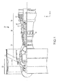
- FIG. 1 is a schematic diagram of an exemplary embodiment of a gas turbine engine 20.
- the gas turbine engine 20 is depicted as a turbofan that incorporates a fan section 22, a compressor section 24, a combustion section 26, and a turbine section 28.
- a mid-turbine frame 57 of engine static structure 36 may be located generally between HPT 54 and low pressure turbine 46. It is to be understood that the concepts as disclosed herein are not limited in application to the depicted embodiment of a gas turbine engine 20, but are applicable to other types of gas turbine engines, such as those used to power modem aircraft, to power sea vessels, to generate electrical power, and in industrial applications.
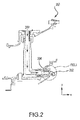
- Mid-turbine frame assembly 257 may include supply tube 204.
- Supply tube 204 may supply cooling air 280 to swirler tube 202.
- swirler tube 202 may supply cooling air to a turbine section of gas turbine engine 20.
- swirler tube 302 may include flange 314, a tube 312 extending away from flange 314, and a metering feature 310.
- Supply tube 304 may comprise a supply tube diameter " D SUPPLY ".
- Flange 314 may be coupled to mid turbine frame assembly 357.
- Flange 314 may be located at inlet 316 of swirler tube 302.
- Inlet 316 of swirler tube may be that portion of swirler tube 302 where cooling air 380 enters swirler tube 302 from a fluid supply.
- Tube 312 may be configured to turn the flow of cooling air 380 via a bent portion of tube 312. It may be desirable to have swirler tube 302 turn the flow of cooling air 380 in order to "pre turn" cooling air 380 such that cooling air 380 exits swirler tube 302 in a direction of the rotation of a turbine rotor. According to various embodiments, the inner surface of tube 312 and flange 314 may be referred to as a flow surface 318.
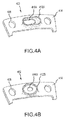
- tube 412A may comprise an elliptical shape.
- inlet 416A may comprise an elliptical shape.
- tube 412B may comprise a circular shape.
- inlet 416B may comprise a circular shape.
- the shape of tube 412A may be determined by the space available in an engine assembly for swirler tube 402.
- swirler tube 402 may include fastener aperture 408 disposed on flange 414.
- fastener aperture 408 may be an aperture configured to allow a fastener to enter through fastener aperture 408 and attach swirler tube 402 to at least a portion of an engine, including a mid-turbine frame, for example.
- swirler tube 402 may comprise a moderate to high temperature metal alloy.
- swirler tube 402 may comprise a nickel-based superalloy.
- swirler tube 402 may comprise an austenitic nickel-chromium-based alloy such as Inconel®, which is available from Special Metals Corporation of New Hartford, New York, USA.
- swirler tube 402 may comprise a high temperature stainless steel.
- Metering feature 510A may be integral to swirler tube 502.
- An integral metering feature may eliminate vibration and may decrease manufacturing costs and total part counts in engine assemblies.
- An integral metering feature allows for a thicker metering feature that may be manufactured to a desired geometry such as a chamfer, for example.
- Metering feature 510A may comprise a metered diameter labeled as "d". It may be desirable to limit (or meter) the flow rate of cooling air 580 into a component aft (in the positive x-direction) of swirler tube 502. Accordingly, metering feature 510A may be configured to meter the flow rate of cooling air 580. Metered diameter "d” may be less than the inlet diameter " D INLET ".
- "d”, " D INLET ", and “ D SUPPLY” may partially define cross sectional areas “A” (cross sectional area at the most narrow portion of the metering feature), " A INLET “( cross sectional area of the inlet of the siwrler tube), and " A SUPPLY " (cross sectional area of the inlet).
- Metered area "A” may be a percentage of inlet cross sectional area.
- A may be in the range of about fifteen percent (15%) and eighty-five percent (85%) of " A INLET ,” in accordance with various embodiments.
- a INLET is ten (10) square inches (64.5 cm 2 ) and the metered area is seventy percent (70%) of the inlet area, then the metered area would be seven (7) square inches (45.2 cm 2 ).
- the inlet area " A INLETi " may be a percentage of supply area " A SUPPLY "i , in the range of about fifty percent (50%) and one hundred percent (100%), in accordance with various embodiments.
- D outlet is the diameter of tube 312 aft of metering feature 310 and A outlet is the cross sectional area of the tube 312.
- a outlet > A and, accordingly, D outlet >d.
- the shape of metering feature 510A may comprise a chamfer.
- a chamfer may be desirable in order to allow smoother air flow through swirler tube 502.
- a chamfer may decrease flow energy loss relative to more harsh geometric shapes such as a square, for example.
- a schematic view of a metered swirler tube comprising a convex fillet feature is illustrated.
- a convex fillet may be desirable in order to allow smooth air flow through swirler tube 502.
- a convex fillet may decrease flow energy loss relative to more harsh geometric shapes such as a square, for example.
- a method of metering fluid flow in a gas turbine engine comprising conducting cooling air into a mid-turbine frame of a gas turbine engine at a first diameter (D supply ).
- the cooling air may be metered via metering feature 310, the metering feature having a metering feature diameter (d, with brief reference to FIGs. 5A and 5B ) that is less than (D supply ), expanding the cooling air upon exit of the metering feature.
- the cooling air may be expanded to D Outlet .
- swirler tube 502 may be manufactured via any of several manufacturing methods. According to various embodiments, swirler tube 502 may be manufactured via at least one or more of an additive manufacturing process and a subtractive manufacturing process.
- references to "one embodiment”, “an embodiment”, “an example embodiment”, etc. indicate that the embodiment described may include a particular feature, structure, or characteristic, but every embodiment may not necessarily include the particular feature, structure, or characteristic. Moreover, such phrases are not necessarily referring to the same embodiment. Further, when a particular feature, structure, or characteristic is described in connection with an embodiment, it is submitted that it is within the knowledge of one skilled in the art to affect such feature, structure, or characteristic in connection with other embodiments whether or not explicitly described. After reading the description, it will be apparent to one skilled in the relevant art(s) how to implement the disclosure in alternative embodiments.
Landscapes
- Engineering & Computer Science (AREA)
- Mechanical Engineering (AREA)
- General Engineering & Computer Science (AREA)
- Chemical & Material Sciences (AREA)
- Combustion & Propulsion (AREA)
- Turbine Rotor Nozzle Sealing (AREA)
Abstract
Description
- The present disclosure relates to metering features and more specifically to metering features in a swirler tube of a gas turbine engine.
- Swirler tubes in gas turbine engines may be used to supply cooling air to a turbine portion of a gas turbine engine. Modulation of cooling air entering a swirler tube may be desirable.
- A swirler tube is disclosed. A swirler is provided comprising a flange defining a first surface, a tube extending away from the first surface, a flow surface defined by a flange inner surface and a tube inner surface, the flange inner surface having an inlet diameter, and a metering feature disposed on the flow surface, wherein the metering feature is integral to the tube, the metering feature have a metering feature diameter that is less than the inlet diameter.
- A mid-turbine frame of a gas turbine engine is provided comprising a cooling air fluid supply, a swirler tube coupled to the cooling air fluid supply, the swirler tube comprising, a flange defining a first surface, a tube extending away from the first surface, a flow surface defined by a flange inner surface and a tube inner surface, the flange inner surface having an inlet diameter, and a metering feature disposed on the flow surface, wherein the metering feature is integral to the tube, the metering feature have a metering feature diameter that is less than the inlet diameter, wherein the tube has a curved portion.
- A method of metering fluid flow in a gas turbine engine is provided comprising conducting cooling air into a mid-turbine frame of a gas turbine engine at a first diameter, metering the cooling air via a metering feature, the metering feature having a metering feature diameter that is less than the first diameter, expanding the cooling air upon exit of the metering feature.
- The subject matter of the present disclosure is particularly pointed out and distinctly claimed in the concluding portion of the specification. A more complete understanding of the present disclosure, however, may best be obtained by referring to the detailed description and claims when considered in connection with the drawing figures, wherein like numerals denote like elements.
-
FIG. 1 illustrates an exemplary gas turbine engine, in accordance with various embodiments; -
FIG. 2 illustrates a schematic view of a mid-turbine frame of a gas turbine engine, in accordance with various embodiments; -
FIG. 3 illustrates an enlarged schematic view of a mid-turbine frame of a gas turbine engine, in accordance with various embodiments; -
FIG. 4A illustrates an isometric view of a metered swirler tube with an elliptical inlet, in accordance with various embodiments; -
FIG. 4B illustrates an isometric view of a metered swirler tube with a circular inlet, in accordance with various embodiments; -
FIG. 5A illustrates a schematic view of a metered swirler tube comprising a chamfered metering feature, in accordance with various embodiments; and -
FIG. 5B illustrates a schematic view of a metered swirler tube comprising a convex fillet metering feature, in accordance with various embodiments. - The detailed description of exemplary embodiments herein makes reference to the accompanying drawings, which show exemplary embodiments by way of illustration and their best mode. While these exemplary embodiments are described in sufficient detail to enable those skilled in the art to practice the disclosure, it should be understood that other embodiments may be realized and that logical, material, and mechanical changes may be made without departing from the scope of the disclosure. Thus, the detailed description herein is presented for purposes of illustration only and not of limitation. For example, the steps recited in any of the method or process descriptions may be executed in any order and are not necessarily limited to the order presented. Furthermore, any reference to singular includes plural embodiments, and any reference to more than one component or step may include a singular embodiment or step. Also, any reference to attached, fixed, connected or the like may include permanent, removable, temporary, partial, full and/or any other possible attachment option. Additionally, any reference to "without contact" (or similar phrases) may also include reduced contact or minimal contact.
- Swirler tubes (also referred to as swirlers) in gas turbine engines may be used to supply cooling air to a turbine portion of a gas turbine engine. Swirler tubes may include a metering feature to limit the flow rate of the cooling air through the swirler tube. Metering features may be disposed between a flange portion of the swirler tube and the mid turbine frame of a gas turbine engine. If a metering feature is manufactured as a separate component from the swirler tube, the metering feature may be incorrectly installed and cause undesirable vibration during operation. Furthermore, it may be unpractical to manufacture metering features which are separate from the swirler tube to a desirable geometry.
-
FIG. 1 is a schematic diagram of an exemplary embodiment of agas turbine engine 20. Thegas turbine engine 20 is depicted as a turbofan that incorporates afan section 22, acompressor section 24, acombustion section 26, and aturbine section 28. Amid-turbine frame 57 of enginestatic structure 36 may be located generally between HPT 54 andlow pressure turbine 46. It is to be understood that the concepts as disclosed herein are not limited in application to the depicted embodiment of agas turbine engine 20, but are applicable to other types of gas turbine engines, such as those used to power modem aircraft, to power sea vessels, to generate electrical power, and in industrial applications. - In various embodiments and with reference to
FIG. 2 , a mid-turbine frame assembly is illustrated with an x-y coordinate system for reference.Mid-turbine frame assembly 257 may includesupply tube 204.Supply tube 204 may supplycooling air 280 toswirler tube 202. With brief reference toFIG 1 ,swirler tube 202 may supply cooling air to a turbine section ofgas turbine engine 20. - In various embodiments and with reference to
FIG. 3 , an enlarged schematic view of a mid-turbine frame of a gas turbine engine is illustrated with an x-y coordinate system for reference. According to various embodiments,swirler tube 302 may includeflange 314, atube 312 extending away fromflange 314, and ametering feature 310.Supply tube 304 may comprise a supply tube diameter "DSUPPLY ".Flange 314 may be coupled to midturbine frame assembly 357.Flange 314 may be located atinlet 316 ofswirler tube 302.Inlet 316 of swirler tube may be that portion ofswirler tube 302 wherecooling air 380 entersswirler tube 302 from a fluid supply. Tube 312 may be configured to turn the flow of coolingair 380 via a bent portion oftube 312. It may be desirable to haveswirler tube 302 turn the flow ofcooling air 380 in order to "pre turn"cooling air 380 such thatcooling air 380exits swirler tube 302 in a direction of the rotation of a turbine rotor. According to various embodiments, the inner surface oftube 312 andflange 314 may be referred to as aflow surface 318. - In various embodiments and with reference to
FIG. 4A and FIG. 4B , an isometric view of a metered swirler tube with an elliptical and a circular inlet respectively is illustrated. In this illustration, part of the swirler tube is removed for ease of illustration. According to various embodiments,tube 412A may comprise an elliptical shape. According to various embodiments,inlet 416A may comprise an elliptical shape. According to various embodiments,tube 412B may comprise a circular shape. According to various embodiments,inlet 416B may comprise a circular shape. The shape oftube 412A may be determined by the space available in an engine assembly forswirler tube 402. - According to various embodiments,
swirler tube 402 may includefastener aperture 408 disposed onflange 414. According to various embodiments,fastener aperture 408 may be an aperture configured to allow a fastener to enter throughfastener aperture 408 and attachswirler tube 402 to at least a portion of an engine, including a mid-turbine frame, for example. - According to various embodiments,
swirler tube 402 may comprise a moderate to high temperature metal alloy. According to various embodiments,swirler tube 402 may comprise a nickel-based superalloy. For example,swirler tube 402 may comprise an austenitic nickel-chromium-based alloy such as Inconel®, which is available from Special Metals Corporation of New Hartford, New York, USA. According to various embodiments,swirler tube 402 may comprise a high temperature stainless steel. - In various embodiments and with reference to
FIG. 5A , a schematic view of a metered swirler tube comprising a chamfered metering feature is illustrated.Metering feature 510A may be integral toswirler tube 502. An integral metering feature may eliminate vibration and may decrease manufacturing costs and total part counts in engine assemblies. An integral metering feature allows for a thicker metering feature that may be manufactured to a desired geometry such as a chamfer, for example. -
Metering feature 510A may comprise a metered diameter labeled as "d". It may be desirable to limit (or meter) the flow rate of coolingair 580 into a component aft (in the positive x-direction) ofswirler tube 502. Accordingly,metering feature 510A may be configured to meter the flow rate of coolingair 580. Metered diameter "d" may be less than the inlet diameter "DINLET ". With further reference toFIG. 3 , "d", "DINLET ", and "DSUPPLY " may partially define cross sectional areas "A" (cross sectional area at the most narrow portion of the metering feature), "AINLET "(cross sectional area of the inlet of the siwrler tube), and "ASUPPLY " (cross sectional area of the inlet). For example, if the shape offlow surface 318 is circular, the cross section area "A" may be defined as the square of half of the metered diameter, labeled as "d", times π: [A=π*(d/2)2]. Metered area "A" may be a percentage of inlet cross sectional area. For example, A may be in the range of about fifteen percent (15%) and eighty-five percent (85%) of "AINLET ," in accordance with various embodiments. For example, if the "AINLET ," is ten (10) square inches (64.5 cm2) and the metered area is seventy percent (70%) of the inlet area, then the metered area would be seven (7) square inches (45.2 cm2). The inlet area "AINLETi" may be a percentage of supply area "ASUPPLY "i, in the range of about fifty percent (50%) and one hundred percent (100%), in accordance with various embodiments. - With reference to
FIG. 3 , Doutlet is the diameter oftube 312 aft ofmetering feature 310 and Aoutlet is the cross sectional area of thetube 312. In various embodiments, Aoutlet > A and, accordingly, Doutlet >d. - In accordance with various embodiments, the shape of
metering feature 510A may comprise a chamfer. According to various embodiments, a chamfer may be desirable in order to allow smoother air flow throughswirler tube 502. According to various embodiments, a chamfer may decrease flow energy loss relative to more harsh geometric shapes such as a square, for example. - In various embodiments and with reference to
FIG. 5B , a schematic view of a metered swirler tube comprising a convex fillet feature is illustrated. According to various embodiments, a convex fillet may be desirable in order to allow smooth air flow throughswirler tube 502. According to various embodiments, a convex fillet may decrease flow energy loss relative to more harsh geometric shapes such as a square, for example. - With reference to
FIG. 3 , a method of metering fluid flow in a gas turbine engine is provided comprising conducting cooling air into a mid-turbine frame of a gas turbine engine at a first diameter (Dsupply). The cooling air may be metered viametering feature 310, the metering feature having a metering feature diameter (d, with brief reference toFIGs. 5A and 5B ) that is less than (Dsupply), expanding the cooling air upon exit of the metering feature. For example, the cooling air may be expanded to DOutlet. - According to various embodiments,
swirler tube 502 may be manufactured via any of several manufacturing methods. According to various embodiments,swirler tube 502 may be manufactured via at least one or more of an additive manufacturing process and a subtractive manufacturing process. - Benefits, other advantages, and solutions to problems have been described herein with regard to specific embodiments. Furthermore, the connecting lines shown in the various figures contained herein are intended to represent exemplary functional relationships and/or physical couplings between the various elements. It should be noted that many alternative or additional functional relationships or physical connections may be present in a practical system. However, the benefits, advantages, solutions to problems, and any elements that may cause any benefit, advantage, or solution to occur or become more pronounced are not to be construed as critical, required, or essential features or elements of the disclosed embodiments. The scope of the claimed embodiments is accordingly to be limited by nothing other than the appended claims, in which reference to an element in the singular is not intended to mean "one and only one" unless explicitly so stated, but rather "one or more." Moreover, where a phrase similar to "at least one of A, B, or C" is used in the claims, it is intended that the phrase be interpreted to mean that A alone may be present in an embodiment, B alone may be present in an embodiment, C alone may be present in an embodiment, or that any combination of the elements A, B and C may be present in a single embodiment; for example, A and B, A and C, B and C, or A and B and C. Different cross-hatching is used throughout the figures to denote different parts but not necessarily to denote the same or different materials.
- Systems, methods and apparatus are provided herein. In the detailed description herein, references to "one embodiment", "an embodiment", "an example embodiment", etc., indicate that the embodiment described may include a particular feature, structure, or characteristic, but every embodiment may not necessarily include the particular feature, structure, or characteristic. Moreover, such phrases are not necessarily referring to the same embodiment. Further, when a particular feature, structure, or characteristic is described in connection with an embodiment, it is submitted that it is within the knowledge of one skilled in the art to affect such feature, structure, or characteristic in connection with other embodiments whether or not explicitly described. After reading the description, it will be apparent to one skilled in the relevant art(s) how to implement the disclosure in alternative embodiments.
Claims (14)
- A swirler comprising:a flange (314; 414) defining a first surface;a tube (312; 412A; 412B) extending away from the first surface;a flow surface defined by a flange inner surface and a tube inner surface, the flange inner surface having an inlet diameter (DINLET); anda metering feature (310; 510A; 510B) disposed on the flow surface, wherein the metering feature (310; 510A; 510B) is integral to the tube (312; 412A; 412B), the metering feature (310; 510A; 510B) have a metering feature diameter (d) that is less than the inlet diameter (DINLET).
- The swirler of claim 1, wherein the metering feature (310; 510A; 510B) comprises a chamfer.
- The swirler of claim 1, wherein the metering feature (310; 510A; 510B) comprises a convex fillet.
- The swirler of claim 1, 2 or 3, wherein the metering feature (310; 510A; 510B) is manufactured via at least one of an additive process or a subtractive process.
- The swirler of any preceding claim, wherein the metering feature diameter (d) is between 15% and 85% of the inlet diameter (DINLET).
- The swirler of any preceding claim, wherein the tube (312; 412A; 412B) comprises an inlet end and an outlet end, the outlet end being located opposite the inlet end.
- The swirler of claim 6, wherein the flange (314; 414) is located at the inlet end.
- The swirler of claim 6 or 7, wherein the metering feature (310; 510A; 510B) is located proximate the inlet end.
- The swirler of any preceding claim, wherein the tube (312; 412A; 412B) is configured to be coupled to a fluid supply via the flange (314; 414).
- A mid-turbine frame of a gas turbine engine (20) comprising:a cooling air fluid supply; andthe swirler of any preceding claim coupled to the cooling air fluid supply, wherein the tube (312; 412A; 412B) has a curved portion.
- The mid-turbine frame of a gas turbine engine of claim 10, wherein the cooling air fluid supply is coupled to the swirler proximate the inlet end.
- The swirler or mid-turbine frame of any preceding claim, wherein the flange (314; 414) comprises an aperture (408).
- A method of metering fluid flow in a gas turbine engine (20) comprising:conducting cooling air into a mid-turbine frame of the gas turbine engine (20) at a first diameter (DINLET);metering the cooling air via a metering feature (310; 510A; 510B), the metering feature (310; 510A; 510B) having a metering feature diameter (d) that is less than the first diameter (DINLET);expanding the cooling air upon exit of the metering feature (310; 510A; 510B).
- The method of metering fluid flow in a gas turbine engine of claim 13, further comprising turning the cooling air.
Applications Claiming Priority (1)
| Application Number | Priority Date | Filing Date | Title |
|---|---|---|---|
| US14/656,230 US9896939B2 (en) | 2015-03-12 | 2015-03-12 | Integral metering feature, systems and methods |
Publications (2)
| Publication Number | Publication Date |
|---|---|
| EP3067533A1 true EP3067533A1 (en) | 2016-09-14 |
| EP3067533B1 EP3067533B1 (en) | 2019-12-04 |
Family
ID=55628724
Family Applications (1)
| Application Number | Title | Priority Date | Filing Date |
|---|---|---|---|
| EP16159260.5A Active EP3067533B1 (en) | 2015-03-12 | 2016-03-08 | Integral metering feature, system and method |
Country Status (2)
| Country | Link |
|---|---|
| US (1) | US9896939B2 (en) |
| EP (1) | EP3067533B1 (en) |
Cited By (1)
| Publication number | Priority date | Publication date | Assignee | Title |
|---|---|---|---|---|
| EP3315228A1 (en) * | 2016-10-27 | 2018-05-02 | United Technologies Corporation | Additively manufactured component for a gas powered turbine |
Families Citing this family (3)
| Publication number | Priority date | Publication date | Assignee | Title |
|---|---|---|---|---|
| US20180223673A1 (en) * | 2017-02-07 | 2018-08-09 | General Electric Company | Hot gas path component with metering structure including converging-diverging passage portions |
| US11346249B2 (en) * | 2019-03-05 | 2022-05-31 | Pratt & Whitney Canada Corp. | Gas turbine engine with feed pipe for bearing housing |
| GB2637529B (en) * | 2024-01-26 | 2026-04-01 | Siemens Energy Global Gmbh & Co Kg | Heat cover for rotor of gas turbine engine |
Citations (5)
| Publication number | Priority date | Publication date | Assignee | Title |
|---|---|---|---|---|
| US20080253884A1 (en) * | 2007-04-12 | 2008-10-16 | United Technologies Corporation | Out-flow margin protection for a gas turbine engine |
| US20110189000A1 (en) * | 2007-05-01 | 2011-08-04 | General Electric Company | System for regulating a cooling fluid within a turbomachine |
| US20130219919A1 (en) * | 2012-02-27 | 2013-08-29 | Gabriel L. Suciu | Gas turbine engine buffer cooling system |
| US20140003920A1 (en) * | 2012-07-02 | 2014-01-02 | United Technologies Corporation | Flow metering anti-rotation outer diameter (od) hex nut |
| EP3045672A1 (en) * | 2015-01-16 | 2016-07-20 | United Technologies Corporation | Cooling passages for a mid-turbine frame |
Family Cites Families (6)
| Publication number | Priority date | Publication date | Assignee | Title |
|---|---|---|---|---|
| US1096508A (en) * | 1908-07-20 | 1914-05-12 | Hoppes Mfg Company | Water-distributer for feed-water heaters. |
| US2632672A (en) * | 1949-11-15 | 1953-03-24 | Russell R Waterman | Steam generator |
| CH355327A (en) * | 1959-07-27 | 1961-06-30 | Bbc Brown Boveri & Cie | Axial turbine, in particular gas turbine |
| US3286461A (en) * | 1965-07-22 | 1966-11-22 | Gen Motors Corp | Turbine starter and cooling |
| FR2748553B1 (en) * | 1996-05-09 | 1998-06-19 | Snecma | INJECTION SYSTEM WITH VARIABLE GEOMETRY ADOPTING AIR FLOW ACCORDING TO ENGINE RPM |
| US8561426B2 (en) * | 2008-08-13 | 2013-10-22 | Trane International Inc. | Crimped orifice for flare fitting |
-
2015
- 2015-03-12 US US14/656,230 patent/US9896939B2/en active Active
-
2016
- 2016-03-08 EP EP16159260.5A patent/EP3067533B1/en active Active
Patent Citations (5)
| Publication number | Priority date | Publication date | Assignee | Title |
|---|---|---|---|---|
| US20080253884A1 (en) * | 2007-04-12 | 2008-10-16 | United Technologies Corporation | Out-flow margin protection for a gas turbine engine |
| US20110189000A1 (en) * | 2007-05-01 | 2011-08-04 | General Electric Company | System for regulating a cooling fluid within a turbomachine |
| US20130219919A1 (en) * | 2012-02-27 | 2013-08-29 | Gabriel L. Suciu | Gas turbine engine buffer cooling system |
| US20140003920A1 (en) * | 2012-07-02 | 2014-01-02 | United Technologies Corporation | Flow metering anti-rotation outer diameter (od) hex nut |
| EP3045672A1 (en) * | 2015-01-16 | 2016-07-20 | United Technologies Corporation | Cooling passages for a mid-turbine frame |
Cited By (2)
| Publication number | Priority date | Publication date | Assignee | Title |
|---|---|---|---|---|
| EP3315228A1 (en) * | 2016-10-27 | 2018-05-02 | United Technologies Corporation | Additively manufactured component for a gas powered turbine |
| US10975703B2 (en) | 2016-10-27 | 2021-04-13 | Raytheon Technologies Corporation | Additively manufactured component for a gas powered turbine |
Also Published As
| Publication number | Publication date |
|---|---|
| US9896939B2 (en) | 2018-02-20 |
| EP3067533B1 (en) | 2019-12-04 |
| US20160265360A1 (en) | 2016-09-15 |
Similar Documents
| Publication | Publication Date | Title |
|---|---|---|
| EP3060830B1 (en) | Annular cartridge seal | |
| US10082039B2 (en) | Segmented annular seal | |
| US10107302B2 (en) | Durable riblets for engine environment | |
| EP3067533A1 (en) | Integral metering feature, system and method | |
| EP3112599B1 (en) | Transfer tube and turbine section comprising transfer tube | |
| EP3269940A1 (en) | Compressor and corresponding gas turbine engine with such a compressor | |
| JP6730031B2 (en) | Fixing jig and method for mounting turbine blades | |
| US10655489B2 (en) | Systems and methods for assembling flow path components | |
| EP3012407A1 (en) | Film hole with protruding flow accumulator | |
| JP6870964B2 (en) | CMC thermal clamp | |
| EP3477047B1 (en) | Segmented structural links for coupled disk frequency tuning and corresponding gas turbine engine with such links | |
| EP3232018A1 (en) | Heat shield with axial retention lock | |
| US10392945B2 (en) | Turbomachine cooling system | |
| US11371372B2 (en) | Beveled coverplate | |
| US11066951B2 (en) | Wear liner for fixed stator vanes | |
| US10215037B2 (en) | Contoured retaining ring | |
| EP3441568B1 (en) | Turbomachine impingement cooling insert | |
| US10208604B2 (en) | Cooling features with three dimensional chevron geometry | |
| EP3553278B1 (en) | Axial stiffening ribs/augmentation fins | |
| US9745864B2 (en) | Systems and methods for anti-rotational features | |
| US20200355271A1 (en) | Seal strip for seal assembly and method to form same | |
| US8690530B2 (en) | System and method for supporting a nozzle assembly | |
| EP3190269A1 (en) | Low energy wake stage |
Legal Events
| Date | Code | Title | Description |
|---|---|---|---|
| PUAI | Public reference made under article 153(3) epc to a published international application that has entered the european phase |
Free format text: ORIGINAL CODE: 0009012 |
|
| AK | Designated contracting states |
Kind code of ref document: A1 Designated state(s): AL AT BE BG CH CY CZ DE DK EE ES FI FR GB GR HR HU IE IS IT LI LT LU LV MC MK MT NL NO PL PT RO RS SE SI SK SM TR |
|
| AX | Request for extension of the european patent |
Extension state: BA ME |
|
| RAP1 | Party data changed (applicant data changed or rights of an application transferred) |
Owner name: UNITED TECHNOLOGIES CORPORATION |
|
| STAA | Information on the status of an ep patent application or granted ep patent |
Free format text: STATUS: REQUEST FOR EXAMINATION WAS MADE |
|
| 17P | Request for examination filed |
Effective date: 20170314 |
|
| RBV | Designated contracting states (corrected) |
Designated state(s): AL AT BE BG CH CY CZ DE DK EE ES FI FR GB GR HR HU IE IS IT LI LT LU LV MC MK MT NL NO PL PT RO RS SE SI SK SM TR |
|
| STAA | Information on the status of an ep patent application or granted ep patent |
Free format text: STATUS: EXAMINATION IS IN PROGRESS |
|
| 17Q | First examination report despatched |
Effective date: 20180601 |
|
| GRAP | Despatch of communication of intention to grant a patent |
Free format text: ORIGINAL CODE: EPIDOSNIGR1 |
|
| STAA | Information on the status of an ep patent application or granted ep patent |
Free format text: STATUS: GRANT OF PATENT IS INTENDED |
|
| INTG | Intention to grant announced |
Effective date: 20190614 |
|
| GRAS | Grant fee paid |
Free format text: ORIGINAL CODE: EPIDOSNIGR3 |
|
| GRAA | (expected) grant |
Free format text: ORIGINAL CODE: 0009210 |
|
| STAA | Information on the status of an ep patent application or granted ep patent |
Free format text: STATUS: THE PATENT HAS BEEN GRANTED |
|
| AK | Designated contracting states |
Kind code of ref document: B1 Designated state(s): AL AT BE BG CH CY CZ DE DK EE ES FI FR GB GR HR HU IE IS IT LI LT LU LV MC MK MT NL NO PL PT RO RS SE SI SK SM TR |
|
| REG | Reference to a national code |
Ref country code: GB Ref legal event code: FG4D |
|
| REG | Reference to a national code |
Ref country code: CH Ref legal event code: EP |
|
| REG | Reference to a national code |
Ref country code: AT Ref legal event code: REF Ref document number: 1209691 Country of ref document: AT Kind code of ref document: T Effective date: 20191215 |
|
| REG | Reference to a national code |
Ref country code: DE Ref legal event code: R096 Ref document number: 602016025351 Country of ref document: DE |
|
| REG | Reference to a national code |
Ref country code: IE Ref legal event code: FG4D |
|
| REG | Reference to a national code |
Ref country code: NL Ref legal event code: MP Effective date: 20191204 |
|
| REG | Reference to a national code |
Ref country code: LT Ref legal event code: MG4D |
|
| PG25 | Lapsed in a contracting state [announced via postgrant information from national office to epo] |
Ref country code: NO Free format text: LAPSE BECAUSE OF FAILURE TO SUBMIT A TRANSLATION OF THE DESCRIPTION OR TO PAY THE FEE WITHIN THE PRESCRIBED TIME-LIMIT Effective date: 20200304 Ref country code: GR Free format text: LAPSE BECAUSE OF FAILURE TO SUBMIT A TRANSLATION OF THE DESCRIPTION OR TO PAY THE FEE WITHIN THE PRESCRIBED TIME-LIMIT Effective date: 20200305 Ref country code: FI Free format text: LAPSE BECAUSE OF FAILURE TO SUBMIT A TRANSLATION OF THE DESCRIPTION OR TO PAY THE FEE WITHIN THE PRESCRIBED TIME-LIMIT Effective date: 20191204 Ref country code: BG Free format text: LAPSE BECAUSE OF FAILURE TO SUBMIT A TRANSLATION OF THE DESCRIPTION OR TO PAY THE FEE WITHIN THE PRESCRIBED TIME-LIMIT Effective date: 20200304 Ref country code: LT Free format text: LAPSE BECAUSE OF FAILURE TO SUBMIT A TRANSLATION OF THE DESCRIPTION OR TO PAY THE FEE WITHIN THE PRESCRIBED TIME-LIMIT Effective date: 20191204 Ref country code: LV Free format text: LAPSE BECAUSE OF FAILURE TO SUBMIT A TRANSLATION OF THE DESCRIPTION OR TO PAY THE FEE WITHIN THE PRESCRIBED TIME-LIMIT Effective date: 20191204 Ref country code: SE Free format text: LAPSE BECAUSE OF FAILURE TO SUBMIT A TRANSLATION OF THE DESCRIPTION OR TO PAY THE FEE WITHIN THE PRESCRIBED TIME-LIMIT Effective date: 20191204 |
|
| PG25 | Lapsed in a contracting state [announced via postgrant information from national office to epo] |
Ref country code: HR Free format text: LAPSE BECAUSE OF FAILURE TO SUBMIT A TRANSLATION OF THE DESCRIPTION OR TO PAY THE FEE WITHIN THE PRESCRIBED TIME-LIMIT Effective date: 20191204 Ref country code: RS Free format text: LAPSE BECAUSE OF FAILURE TO SUBMIT A TRANSLATION OF THE DESCRIPTION OR TO PAY THE FEE WITHIN THE PRESCRIBED TIME-LIMIT Effective date: 20191204 |
|
| PG25 | Lapsed in a contracting state [announced via postgrant information from national office to epo] |
Ref country code: AL Free format text: LAPSE BECAUSE OF FAILURE TO SUBMIT A TRANSLATION OF THE DESCRIPTION OR TO PAY THE FEE WITHIN THE PRESCRIBED TIME-LIMIT Effective date: 20191204 |
|
| PG25 | Lapsed in a contracting state [announced via postgrant information from national office to epo] |
Ref country code: RO Free format text: LAPSE BECAUSE OF FAILURE TO SUBMIT A TRANSLATION OF THE DESCRIPTION OR TO PAY THE FEE WITHIN THE PRESCRIBED TIME-LIMIT Effective date: 20191204 Ref country code: ES Free format text: LAPSE BECAUSE OF FAILURE TO SUBMIT A TRANSLATION OF THE DESCRIPTION OR TO PAY THE FEE WITHIN THE PRESCRIBED TIME-LIMIT Effective date: 20191204 Ref country code: PT Free format text: LAPSE BECAUSE OF FAILURE TO SUBMIT A TRANSLATION OF THE DESCRIPTION OR TO PAY THE FEE WITHIN THE PRESCRIBED TIME-LIMIT Effective date: 20200429 Ref country code: CZ Free format text: LAPSE BECAUSE OF FAILURE TO SUBMIT A TRANSLATION OF THE DESCRIPTION OR TO PAY THE FEE WITHIN THE PRESCRIBED TIME-LIMIT Effective date: 20191204 Ref country code: NL Free format text: LAPSE BECAUSE OF FAILURE TO SUBMIT A TRANSLATION OF THE DESCRIPTION OR TO PAY THE FEE WITHIN THE PRESCRIBED TIME-LIMIT Effective date: 20191204 Ref country code: EE Free format text: LAPSE BECAUSE OF FAILURE TO SUBMIT A TRANSLATION OF THE DESCRIPTION OR TO PAY THE FEE WITHIN THE PRESCRIBED TIME-LIMIT Effective date: 20191204 |
|
| PG25 | Lapsed in a contracting state [announced via postgrant information from national office to epo] |
Ref country code: IS Free format text: LAPSE BECAUSE OF FAILURE TO SUBMIT A TRANSLATION OF THE DESCRIPTION OR TO PAY THE FEE WITHIN THE PRESCRIBED TIME-LIMIT Effective date: 20200404 Ref country code: SK Free format text: LAPSE BECAUSE OF FAILURE TO SUBMIT A TRANSLATION OF THE DESCRIPTION OR TO PAY THE FEE WITHIN THE PRESCRIBED TIME-LIMIT Effective date: 20191204 Ref country code: SM Free format text: LAPSE BECAUSE OF FAILURE TO SUBMIT A TRANSLATION OF THE DESCRIPTION OR TO PAY THE FEE WITHIN THE PRESCRIBED TIME-LIMIT Effective date: 20191204 |
|
| REG | Reference to a national code |
Ref country code: DE Ref legal event code: R097 Ref document number: 602016025351 Country of ref document: DE |
|
| REG | Reference to a national code |
Ref country code: AT Ref legal event code: MK05 Ref document number: 1209691 Country of ref document: AT Kind code of ref document: T Effective date: 20191204 |
|
| PLBE | No opposition filed within time limit |
Free format text: ORIGINAL CODE: 0009261 |
|
| STAA | Information on the status of an ep patent application or granted ep patent |
Free format text: STATUS: NO OPPOSITION FILED WITHIN TIME LIMIT |
|
| PG25 | Lapsed in a contracting state [announced via postgrant information from national office to epo] |
Ref country code: MC Free format text: LAPSE BECAUSE OF FAILURE TO SUBMIT A TRANSLATION OF THE DESCRIPTION OR TO PAY THE FEE WITHIN THE PRESCRIBED TIME-LIMIT Effective date: 20191204 Ref country code: DK Free format text: LAPSE BECAUSE OF FAILURE TO SUBMIT A TRANSLATION OF THE DESCRIPTION OR TO PAY THE FEE WITHIN THE PRESCRIBED TIME-LIMIT Effective date: 20191204 |
|
| REG | Reference to a national code |
Ref country code: CH Ref legal event code: PL |
|
| 26N | No opposition filed |
Effective date: 20200907 |
|
| PG25 | Lapsed in a contracting state [announced via postgrant information from national office to epo] |
Ref country code: SI Free format text: LAPSE BECAUSE OF FAILURE TO SUBMIT A TRANSLATION OF THE DESCRIPTION OR TO PAY THE FEE WITHIN THE PRESCRIBED TIME-LIMIT Effective date: 20191204 Ref country code: AT Free format text: LAPSE BECAUSE OF FAILURE TO SUBMIT A TRANSLATION OF THE DESCRIPTION OR TO PAY THE FEE WITHIN THE PRESCRIBED TIME-LIMIT Effective date: 20191204 Ref country code: PL Free format text: LAPSE BECAUSE OF FAILURE TO SUBMIT A TRANSLATION OF THE DESCRIPTION OR TO PAY THE FEE WITHIN THE PRESCRIBED TIME-LIMIT Effective date: 20191204 |
|
| REG | Reference to a national code |
Ref country code: BE Ref legal event code: MM Effective date: 20200331 |
|
| PG25 | Lapsed in a contracting state [announced via postgrant information from national office to epo] |
Ref country code: LU Free format text: LAPSE BECAUSE OF NON-PAYMENT OF DUE FEES Effective date: 20200308 |
|
| PG25 | Lapsed in a contracting state [announced via postgrant information from national office to epo] |
Ref country code: LI Free format text: LAPSE BECAUSE OF NON-PAYMENT OF DUE FEES Effective date: 20200331 Ref country code: CH Free format text: LAPSE BECAUSE OF NON-PAYMENT OF DUE FEES Effective date: 20200331 Ref country code: IE Free format text: LAPSE BECAUSE OF NON-PAYMENT OF DUE FEES Effective date: 20200308 Ref country code: IT Free format text: LAPSE BECAUSE OF FAILURE TO SUBMIT A TRANSLATION OF THE DESCRIPTION OR TO PAY THE FEE WITHIN THE PRESCRIBED TIME-LIMIT Effective date: 20191204 |
|
| PG25 | Lapsed in a contracting state [announced via postgrant information from national office to epo] |
Ref country code: BE Free format text: LAPSE BECAUSE OF NON-PAYMENT OF DUE FEES Effective date: 20200331 |
|
| PG25 | Lapsed in a contracting state [announced via postgrant information from national office to epo] |
Ref country code: TR Free format text: LAPSE BECAUSE OF FAILURE TO SUBMIT A TRANSLATION OF THE DESCRIPTION OR TO PAY THE FEE WITHIN THE PRESCRIBED TIME-LIMIT Effective date: 20191204 Ref country code: MT Free format text: LAPSE BECAUSE OF FAILURE TO SUBMIT A TRANSLATION OF THE DESCRIPTION OR TO PAY THE FEE WITHIN THE PRESCRIBED TIME-LIMIT Effective date: 20191204 Ref country code: CY Free format text: LAPSE BECAUSE OF FAILURE TO SUBMIT A TRANSLATION OF THE DESCRIPTION OR TO PAY THE FEE WITHIN THE PRESCRIBED TIME-LIMIT Effective date: 20191204 |
|
| PG25 | Lapsed in a contracting state [announced via postgrant information from national office to epo] |
Ref country code: MK Free format text: LAPSE BECAUSE OF FAILURE TO SUBMIT A TRANSLATION OF THE DESCRIPTION OR TO PAY THE FEE WITHIN THE PRESCRIBED TIME-LIMIT Effective date: 20191204 |
|
| REG | Reference to a national code |
Ref country code: DE Ref legal event code: R081 Ref document number: 602016025351 Country of ref document: DE Owner name: RAYTHEON TECHNOLOGIES CORPORATION (N.D.GES.D.S, US Free format text: FORMER OWNER: UNITED TECHNOLOGIES CORPORATION, FARMINGTON, CONN., US Ref country code: DE Ref legal event code: R081 Ref document number: 602016025351 Country of ref document: DE Owner name: RTX CORPORATION (N.D.GES.D. STAATES DELAWARE),, US Free format text: FORMER OWNER: UNITED TECHNOLOGIES CORPORATION, FARMINGTON, CONN., US |
|
| P01 | Opt-out of the competence of the unified patent court (upc) registered |
Effective date: 20230520 |
|
| REG | Reference to a national code |
Ref country code: DE Ref legal event code: R081 Ref document number: 602016025351 Country of ref document: DE Owner name: RTX CORPORATION (N.D.GES.D. STAATES DELAWARE),, US Free format text: FORMER OWNER: RAYTHEON TECHNOLOGIES CORPORATION (N.D.GES.D.STAATES DELAWARE), ARLINGTON, VA, US |
|
| PGFP | Annual fee paid to national office [announced via postgrant information from national office to epo] |
Ref country code: GB Payment date: 20260219 Year of fee payment: 11 |
|
| PGFP | Annual fee paid to national office [announced via postgrant information from national office to epo] |
Ref country code: DE Payment date: 20260219 Year of fee payment: 11 |
|
| PGFP | Annual fee paid to national office [announced via postgrant information from national office to epo] |
Ref country code: FR Payment date: 20260220 Year of fee payment: 11 |