EP3067532A1 - Adaptable inertial particle separator for a gas turbine engine intake - Google Patents
Adaptable inertial particle separator for a gas turbine engine intake Download PDFInfo
- Publication number
- EP3067532A1 EP3067532A1 EP16159224.1A EP16159224A EP3067532A1 EP 3067532 A1 EP3067532 A1 EP 3067532A1 EP 16159224 A EP16159224 A EP 16159224A EP 3067532 A1 EP3067532 A1 EP 3067532A1
- Authority
- EP
- European Patent Office
- Prior art keywords
- wall
- configuration
- passage
- air
- intake
- Prior art date
- Legal status (The legal status is an assumption and is not a legal conclusion. Google has not performed a legal analysis and makes no representation as to the accuracy of the status listed.)
- Granted
Links
Images


Classifications
-
- F—MECHANICAL ENGINEERING; LIGHTING; HEATING; WEAPONS; BLASTING
- F02—COMBUSTION ENGINES; HOT-GAS OR COMBUSTION-PRODUCT ENGINE PLANTS
- F02C—GAS-TURBINE PLANTS; AIR INTAKES FOR JET-PROPULSION PLANTS; CONTROLLING FUEL SUPPLY IN AIR-BREATHING JET-PROPULSION PLANTS
- F02C7/00—Features, components parts, details or accessories, not provided for in, or of interest apart form groups F02C1/00 - F02C6/00; Air intakes for jet-propulsion plants
- F02C7/04—Air intakes for gas-turbine plants or jet-propulsion plants
- F02C7/05—Air intakes for gas-turbine plants or jet-propulsion plants having provisions for obviating the penetration of damaging objects or particles
- F02C7/052—Air intakes for gas-turbine plants or jet-propulsion plants having provisions for obviating the penetration of damaging objects or particles with dust-separation devices
-
- F—MECHANICAL ENGINEERING; LIGHTING; HEATING; WEAPONS; BLASTING
- F02—COMBUSTION ENGINES; HOT-GAS OR COMBUSTION-PRODUCT ENGINE PLANTS
- F02C—GAS-TURBINE PLANTS; AIR INTAKES FOR JET-PROPULSION PLANTS; CONTROLLING FUEL SUPPLY IN AIR-BREATHING JET-PROPULSION PLANTS
- F02C7/00—Features, components parts, details or accessories, not provided for in, or of interest apart form groups F02C1/00 - F02C6/00; Air intakes for jet-propulsion plants
- F02C7/04—Air intakes for gas-turbine plants or jet-propulsion plants
- F02C7/05—Air intakes for gas-turbine plants or jet-propulsion plants having provisions for obviating the penetration of damaging objects or particles
-
- F—MECHANICAL ENGINEERING; LIGHTING; HEATING; WEAPONS; BLASTING
- F02—COMBUSTION ENGINES; HOT-GAS OR COMBUSTION-PRODUCT ENGINE PLANTS
- F02C—GAS-TURBINE PLANTS; AIR INTAKES FOR JET-PROPULSION PLANTS; CONTROLLING FUEL SUPPLY IN AIR-BREATHING JET-PROPULSION PLANTS
- F02C7/00—Features, components parts, details or accessories, not provided for in, or of interest apart form groups F02C1/00 - F02C6/00; Air intakes for jet-propulsion plants
- F02C7/04—Air intakes for gas-turbine plants or jet-propulsion plants
- F02C7/057—Control or regulation
-
- B—PERFORMING OPERATIONS; TRANSPORTING
- B64—AIRCRAFT; AVIATION; COSMONAUTICS
- B64D—EQUIPMENT FOR FITTING IN OR TO AIRCRAFT; FLIGHT SUITS; PARACHUTES; ARRANGEMENT OR MOUNTING OF POWER PLANTS OR PROPULSION TRANSMISSIONS IN AIRCRAFT
- B64D33/00—Arrangement in aircraft of power plant parts or auxiliaries not otherwise provided for
- B64D33/02—Arrangement in aircraft of power plant parts or auxiliaries not otherwise provided for of combustion air intakes
- B64D2033/0246—Arrangement in aircraft of power plant parts or auxiliaries not otherwise provided for of combustion air intakes comprising particle separators
Definitions
- the present disclosure relates generally to particle separators, and more specifically to an inertial particle separator (IPS), for example, of a gas turbine engine.
- IPS inertial particle separator
- Gas turbine engines are used to power aircraft, watercraft, power generators, and the like.
- Gas turbine engines typically include a compressor, a combustor, and a turbine.
- the compressor compresses air drawn into the engine and delivers high pressure air to the combustor.
- fuel is mixed with the high pressure air and is ignited.
- Products of the combustion reaction in the combustor are directed into the turbine where work is extracted to drive the compressor and, sometimes, an output shaft. Left-over products of the combustion are exhausted out of the turbine and may provide thrust in some applications.
- Air is drawn into the engine through an air intake and communicated to the compressor via an air-intake duct.
- particles may be entrained in the air such as dirt, dust, sand, or liquid and may be drawn into the air intake and passed through the air-intake duct to the compressor.
- Such particles may impact components of the compressor and turbine causing unintended wear.
- the deposit and accumulation of particles may cause fowling and plugging of engine passages. This unintended wear may decrease power output of the engine, shorten the life span of the engine, and lead to increased maintenance costs and increased down time of the engine.
- an inertial particle separator may be utilized.
- the inertial particle separator uses the inertia of the particles to separate the particles from the air.
- the air stream moves through the air-intake duct, the air moves along a serpentine flow path and enters a compressor passage of the air-intake duct while the particles move along a generally linear travel path and enter a scavenge passage included in the air-intake duct.
- particles may deviate from the generally linear travel path and enter the compressor passage rather than the scavenge passage.
- Particles may deviate from the generally linear travel path due separation of flow from an outer wall of the air-intake duct leading to recirculation of the particles and/or other fluid flow phenomenon upstream of the scavenge passage.
- Traditional technologies for particle separation may include a vortex tube and a barrier filter.
- the vortex tube requires a swirl tube structure, which unnecessarily consumes space and weight.
- the barrier filter uses a media to capture particulate, but requires frequent cleaning maintenance.
- inertial particle separators may utilize inflatable boots. However, these inflatable flow surfaces merely constrict or obstruct flow and do not contain translating components for enhanced particle separation. Thus, the capabilities of traditional particle separators are limited.
- transient flow structures may be generated within an internal boundary layer separated flow region. This may sporadically extend the influence of the disturbed flow beyond the time averaged flow behaviors and locally interrupt the flow into the scavenge passage. This interruption may be to the extent of allowing a portion of the air that has entered the scavenge passage, that is laden with particulate, to enter the leg of the particle separator intended for compressor flow only.
- Traditional technologies have limited ability to minimize the formation of transient flow structures or the negative resulting influences on engine performance.
- an adaptive particle separation system To address the above, there is a need for an adaptive particle separation system.
- the need is to reduce the penalties to engine operation caused by the particle separator in when the operational environment causes them to be unneeded or inappropriate. It may be desirable to provide adaptive features such as sensors, active control devices, electrostatics, translating components, and variable control of scavenge passage flow level.
- adaptive features such as sensors, active control devices, electrostatics, translating components, and variable control of scavenge passage flow level.
- an adaptive inertial particle separation system and a method of operating an adaptive inertial particle separation system, as set forth in the appended claims.
- An adaptive inertial particle separation system may include adaptive or switchable features to provide an active or open configuration adapted to split airflow between a scavenge passage and a compressor passage and a passive or closed configuration adapted to pass airflow to the compressor passage while reducing or closing the scavenge passage.
- the system may comprise an air-intake duct including an outer wall spaced apart from a central axis, an inner wall located between the outer wall and the engine rotation axis, an intake passage defined in part by the inner wall and the outer wall, and a splitter located between the outer wall and the inner wall.
- the splitter may define an initial portion of a compressor passage with the inner wall and selectively define a scavenge passage with the outer wall.
- the system may further include a sensor operatively connected to the air-intake duct and operative to initiate at least one of the active features including that of the scavenge passage opened and a passive configuration with the compressor passage increased and the scavenge passage decreased or closed.
- the system may utilize translating flow surfaces to alter the proximity of the splitter relative to the outer and inner walls of the air-intake duct.
- the translation of these surfaces e.g., while substantially maintaining the position of the splitter, causes the intake passage to increase while the scavenge passage is reduced or closed.
- the motion of the flow surfaces forward e.g. opposite of the airflow direction, selectively switches on and off the particle separation function of the system.
- the system also includes additional features that may be used as part of the active configuration. For example, these additional features may assist particle separation.
- the additional features may include any active devices such as a scavenge motive device (e.g., a blower or ejector).
- the features may also include an electrostatic generator configured to selectively direct a charged airstream either toward or away from charged flow surfaces. Alternatively the electrostatic generator may be configured to cluster, e.g., aggregate, particles by combining smaller particles into larger particulates thereby facilitating the flow of clustered particulates toward the scavenge passage.
- the features may also include flow control devices to reduce or defeat highly dynamic fluid flows that result in separator inefficiency. These features may utilize the introduction of airflow produced by compressors in the engine.
- the airflow can be turned on (e.g., in the active configuration) or off (e.g., in the passive configuration).
- the sensor such as a particulate sensor, may also be utilized to selectively switch between the active configuration and the passive configuration and may be positioned to reduce the sensitivity required for the sensor.
- the sensor may be positioned on or near a flow surface of the air-intake duct.
- the sensor may be positioned at a location having relatively higher particulate concentrations, e.g., including the bounce and inertial trajectories of the particulates.
- the switchable features may be configured to achieve relatively high particle separation levels while minimizing engine performance degradations caused by pressure loss at the intake, shaft power extraction, and air bleed withdrawal from the engine gas path.
- the system may also accommodate for the varying particle separation needs of vertical lift aircraft, which may vary based on the operating conditions.
- Switchable features may alter the operation of the particle separator to reduce particle separator pressure loss and engine performance loss at cruise conditions or other conditions having a lower particulate level.
- these switchable features may increase engine fuel efficiency and overall power production through the use of adaptive particle separation features to reduce intake pressure loss, reduce scavenge power requirements, turn off electrostatic generating sources, and reduce or close compressor bleed flows to the separator utilized for flow control.
- FIG. 1 illustrates a block diagram of a turbine engine system 100.
- the system 100 may include a particle separator 102 (e.g., an inertial particle separator (IPS)).
- the particle separator 102 may be operatively part of an aircraft airframe installed ahead of a turbine engine 104 (e.g., also referred to as an engine air particle separator (EAPS)).
- the particle separator 102 may be operatively coupled to a turbine engine 104 (e.g., also referred to as an integral particle separator).
- the turbine engine 104 may include at least one compressor 106 and at least one combustor 108.
- the particle separator 102 may be adapted to any turbine engine.
- the particle separator 102 may adapted to an aircraft such as a helicopter, airplane, unmanned vehicle, fixed wing vehicles, variable wing vehicle, or any other flying vehicle.
- the particle separator 102 may also be adapted for industrial applications, power generators, pumping, naval propulsion, hover crafts, and any other vehicles.
- the particle separator may be configured to receive an intake flow having particulates such as dirt, dust, sand, liquid, or any particulate matter including foreign objects.
- the particle separator 102 splits the intake flow into a scavenge flow (e.g., to be passed away from the compressor 106) and a compressor flow (e.g., to be passed toward the compressor 106).
- the particle separator 102 is configured to separate at least some of particulates from the intake flow such that the particulates are conveyed away from the compressor 106 with the scavenge flow.
- the particulates may be removed from the intake flow with the scavenge flow and the compressor flow is passed to the compressor 106.
- Figures 2a-b illustrate an exemplary duct system 200 of the particle separator 102.
- the duct system may include a sensor 202, a sensor 203, an outer wall 204, an inner wall 206, a splitter 208, an inner splitter surface 207, an outer splitter surface 209, an intake passage 210, a scavenge passage 211, a compressor passage 212, an intake flow 214, a scavenge flow 216, a compressor flow 218, an actuator 220, a flow control device 222, an injector flow 224, and electrostatic generators 226a-c.
- the particle separator 102 may include an active configuration as shown in Figure 2a and a passive configuration as shown in Figure 2b .
- the active configuration may include electrostatic features to energize flow control air flow while it may be flowing.
- the duct system 200 may include an active configuration as shown in Figure 2a and a passive configuration as shown in Figure 2b each resulting from relative translation of duct components by the actuator 220.
- the outer wall 204 may be located in spaced-apart relation to a central axis (e.g., along a centerline CL of the system 100/200) and the inner wall 206 may be located between the outer wall 204 and the central axis.
- the inner wall 206 and the outer wall 204 are arranged to define the intake passage 210.
- the splitter 208 is located between the outer wall 204 and the inner wall 206.
- the splitter 208 is configured to define the separation of intake flow 214.
- the intake flow 214 may separate into the compressor flow 218 of the compressor passage 212 and the scavenge flow of the scavenge passage 211 ( Figure 2a ) or may continue into the compressor flow 218 of the compressor passage 212 ( Figure 2b ), e.g., bypassing the scavenge passage 211.
- the position of the outer wall 204 and inner wall 206 relative to the splitter 208 may determine the whether the scavenge passage 211 is utilized or bypassed.
- the outer wall 204 and inner wall 206 may translate together.
- the outer wall 204 and inner wall 206 may translate by different amounts.
- the outer wall 204 and inner wall 206 may remain stationary while the splitter 208 translates.
- Other combinations of translation are also envisioned. In each case, relative translation is in a direction may be substantially parallel to the central axis. In addition, however, relative rotation of the outer wall 204, inner wall 206, and splitter 208 about the central axis may be adapted to optimize positioning of the flow surfaces.
- the duct system 200 draws the intake flow 214 into the gas turbine engine 10.
- the intake flow includes air and particles.
- the particle separator 102 causes the compressor flow 218 and the scavenge flow 216 to be established as the intake flow 214 moves through the duct system 200.
- a portion of the intake flow 214 may experience boundary layer separation on the outer wall 204 and establish a region of separated flow. This may occur anywhere along duct system 200, e.g., upstream of the scavenge passage 211.
- a portion of the intake flow 214 may sporadically and intermittently separate from the outer wall 204 and enter the compressor flow 218.
- the particles and air trapped in the separated flow region may sometimes flow from the scavenge flow 216 and move into the compressor flow 218. This may allow particles to pass toward compressor 106. As a result, this may potentially result in damage to or degraded performance of the engine 104 including increased wear on duct system 200, turbine 104, compressor 106, and combustor 108.
- the duct system 200 may include the active or open configuration (e.g., Figure 2a ) and the passive or closed configuration (e.g., Figure 2b ).
- the duct system 200 may utilize the active and passive configurations based on a particulate level, e.g., determined by a relative amount of particulates as part of the air.
- the particulate level may be measured, e.g., by sensors 202-203, according to a particulate concentration (e.g., a concentration of particulates per volume of air) and a particulate size distribution (e.g., a statistical distribution of a size of the particles as part of the air).
- the particulate level may be compared to a particulate threshold, which may be used to determine whether to utilize the active or passive configuration. For example, if the particulate level of the intake flow 214 reaches a particulate threshold (e.g., relatively dirty intake flow 214), the active configuration may include a number of active features to minimize particulates from being passed into the compressor flow 218, e.g., including selective activation of the scavenge flow 216, flow control device 222, electrostatics 226, and relative translation of the splitter 208, as described in further detail below.
- a particulate threshold e.g., relatively dirty intake flow 214
- the active configuration may include a number of active features to minimize particulates from being passed into the compressor flow 218, e.g., including selective activation of the scavenge flow 216, flow control device 222, electrostatics 226, and relative translation of the splitter 208, as described in further detail below.
- the passive configuration may allow the intake flow 214 to pass into the compressor flow 218.
- the duct system 200 may utilize selected features of or be positioned at any increment between the active and passive configurations.
- the ducts system 200 control flow through the particle separator 102 based on the particulate threshold, thereby utilizing the active configuration if the intake flow 214 is relatively dirty and utilizing the direct configuration if the intake flow 214 is relatively clean.
- the sensors 202-203 may be utilized to measure the particulate level (e.g., of the intake flow 214) and, in response to the particulate level, the duct system 200 may utilize the active or passive configuration.
- the sensors 202-203 may include one or more sensors configured to measure particulates of air (e.g., as part of the intake flow 214, scavenge flow 216, or compressor flow 218).
- the sensor 202 may include any particulate sensor configured to measure particulate information such as the particulate level as described above or any particulate characteristics such as a size (e.g., fine particulates having a diameter at or greater than 2 micrometers but less than 100 micrometers or coarse particulates having a diameter at or greater than 100 micrometers), type (e.g., liquid or solid), or material (e.g., metallic, water, oil, etc.).
- the sensor 202 may be utilized without or in conjunction with optional sensor component 203, which may include any reflective surface.
- An exemplary sensor 202 may include a laser backscatter detection sensor, laser sensor, electro-optical sensor, infrared sensor, fiber optic sensor, optical position sensor, photodetector, photoelectric sensor, radar sensor, motion sensor, proximity sensor, magnetic sensor, ultrasonic sensor, electric conductivity sensor, or a combination thereof.
- the sensor 202 may include any sensor configured to measure airflow information such as an air flow rate sensor, temperature sensor, pressure sensor, moisture sensor, or altitude sensor.
- the sensor 202 may be alternatively located at the position of sensor component 203.
- the splitter 208 includes the outer splitter surface 207 and the inner splitter surface 209.
- the outer splitter surface 207 cooperates with the outer wall 204 to define the scavenge passage 211 therebetween and the inner splitter surface 209 cooperates with the inner wall 206 to define the compressor passage 212 therebetween.
- the outer wall 204 and inner wall 206 may move away from the splitter 208, while the splitter 208 remains relatively fixed, to decrease or close the scavenge passage 211 and increase the compressor passage 212.
- the splitter 208 may move while the outer wall 204 and inner wall 206 remain relatively fixed.
- outer wall 204, inner wall 206, and splitter 208 may be configured to move or translate relative to any other portion of the system to selectively increase or decrease the scavenge passage 211 and the compressor passage 212.
- the duct system 200 may be selectively operable in the active and passive configurations.
- An exemplary actuator 220 may include a hydraulic (e.g., a cylinder or fluid motor that uses hydraulic power to facilitate mechanical operation), pneumatic (e.g., any device that converts energy formed by vacuum or compressed air into either linear or rotary motion), electric (e.g., a motor that converts electrical energy to mechanical force or torque), or mechanical actuator (e.g., a device that converts rotary motion into linear motion to execute movement such as gears, rails, pulleys, chains, and a rack and pinion).
- a hydraulic e.g., a cylinder or fluid motor that uses hydraulic power to facilitate mechanical operation
- pneumatic e.g., any device that converts energy formed by vacuum or compressed air into either linear or rotary motion
- electric e.g., a motor that converts electrical energy to mechanical force or torque
- mechanical actuator e.g., a device that converts rotary motion into linear motion to execute movement such as gears, rails, pulleys, chains, and a rack and pinion
- the splitter 208 is positioned between the outer wall 204 and inner wall 206 thereby splitting the intake flow 214 into the scavenge flow 216 and the compressor flow 218.
- the splitter 208 is positioned against the outer wall 204 thereby directing the intake flow 214 into compressor flow 218.
- the intake flow 214 may be selectively directed into or bypass the scavenge passage 211.
- the relative positioning of the outer wall 204, inner wall 206, and splitter 208 may be configured to selectively control airflow as part of the active configuration.
- the flow control device 222 may include any device configured to selectively control or direct the airflow of the duct system 200, e.g., as part of the active configuration.
- the flow control device 222 may be configured to provide the injector flow 224 to selectively control the intake flow 214.
- the flow control device 222 may include any air jet injection or suction device configured to cause airflow to enter or leave the duct system 200.
- the flow control device 222 may include any flow control device having adaptable (active - passive) features and may be configured to provide suction or pressure with respect to the airflow of the duct system 200.
- the flow control device 222 may include a suction device configured to provide suction with respect to the duct system 200.
- the flow control device 222 may include a pressure device configured to provide pressure with respect to the duct system 200.
- the flow control device 222 may have opened, intermediate, and closed conditions for adjustable airflow control.
- the flow control device 222 may include a device configured physically modify any flow surface of duct system 200 by selectively providing a recessed surface portion, a smooth surface portion, or a protruded surface portion with respect to the flow surface. As a result, the flow control device 222 may be configured to selectively control airflow as part of the active configuration.
- the electrostatic generators 226a-c may each include any electrostatic device configured to apply a positive or negative charge to matter or gather a plurality of smaller particulates into larger particulates or clusters, e.g., as part of the active configuration.
- the electrostatic generator 226a may be positioned at any location with respect to the duct system 200 (e.g., an intake portion of the duct system 200) and may be configured to apply a positive or negative charge to particulate in the air of intake flow 214.
- the electrostatic generator 226b may be positioned at any location with respect to the duct system 200 (e.g., near the outer wall 204) and may be configured to apply an opposite charge (e.g., a positive charge for negatively charged particulate or a negative charge for positively charged particulate) thereby attracting the oppositely charged particulate in the intake flow 214 and moving the particulate preferentially toward the scavenge passage 211.
- an opposite charge e.g., a positive charge for negatively charged particulate or a negative charge for positively charged particulate
- the electrostatic generator 226c may be positioned at any location with respect to the duct system 200 (e.g., near the inner wall 206) and may be configured to apply like charge to the particulate (e.g., a positive charge for positively charged particulate or a negative charge for negatively charged particulate) thereby repelling the like charged particulate in the intake flow 214 and moving the particulate preferentially away from the compressor passage 218.
- the electrostatic generators 226a-c may be configured to selectively attract or repel particulate as part of the active configuration.
- the system 100 may include a computer system in communication with the sensor 202.
- the computer system may include a processor and a memory communicatively connected to the processor.
- the processor may be configured to instruct the sensor 202 to measure a particulate level, receive the particulate level from the sensor 202, compare the particulate level to a particulate threshold (e.g., stored as part of the memory), and instruct the duct system 200 to utilize the active or passive configuration based on the comparison between the particulate level and particulate threshold.
- a particulate threshold e.g., stored as part of the memory
- the processor may instruct the actuator 220 to position the duct system 200 in the active configuration, e,g., positioning actuator 220 to allow scavenge flow 216, activating flow control device 222, and activating any combination of electrostatic generators 226a-c.
- the processor may instruct the duct system 200 to utilize the passive configuration, e.g., positioning the actuator 220 to close the scavenge flow 216 and direct the intake flow 214 into the compressor flow 218.
- the duct system 200 may be selectively operable between the active and passive configurations based in part on the particulate level and the particulate threshold. It is also contemplated that a mechanical, pneumatic, or electric switch (e.g., a solenoid mechanism), without a processor, may be utilized to selectively switch the ducts system 200 between the active and passive configurations. Additionally, analog driven modulation may be utilized to provide selective intermediate activation of the adaptive components.
- a mechanical, pneumatic, or electric switch e.g., a solenoid mechanism
- analog driven modulation may be utilized to provide selective intermediate activation of the adaptive components.
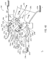
- Figures 3-4a-b illustrate an exemplary duct system 300 of the particle separator 102.
- the duct system 300 may include a plurality of duct systems similar to duct system 200 that are radially-spaced in a radial configuration (e.g., Figure 3 ) or linearly-spaced in a linear configuration.
- the duct system 300 may include outer walls 204a-c, inner walls 206a-c, hubs 308a-c, splitters 208a-c, intake passages 210a-d, scavenge passage 211a-d, compressor passages 212a-d, intake flow 214, scavenge flow 216, compressor flow 218, actuators 220a-e, flow control devices 222a-c, a first end 302, a second end 304, and a shroud 306.
- system 300 is shown in figure 3 with the radial configuration, it is contemplated that any of the embodiments herein may utilized with a linear configuration or a segmented configuration.
- the duct system 300 may be configured as a plurality of duct systems 200, e.g., any single or multi-flow system such as a three-flow system as illustrated in Figure 3 .
- the duct system 300 may receive the intake flow 214 into the intake passages 210a-d and may split into the scavenge flow 216 and compressor flow 218, as discussed above with respect the active configuration of duct system 200.
- the duct system 300 may also receive the intake flow 214, close the scavenge flow 216, and pass the intake flow 214 into the compressor flow 218, as discussed above with respect to the passive configuration of duct system 200.
- the hubs 308a-c and shroud 306 may be movable with respect to the splitters 208a-c to be selectively operable between the active configuration (e.g., Figure 4a ) and passive configuration (e.g., Figure 4b ), as discussed above with respect to the duct system 200.
- the hubs 308a-c and shroud 306 may be simultaneously or sequentially moveable with respect to the splitters 208a-c, e.g., using actuators 220a-e.
- shroud 306, hub 308a, hub 208b, and hub 308c may be positioned toward respective splitters 208a-c thereby utilizing all or any combination of scavenge passages 211a-d.
- all or any combination of shroud 306, hub 308a, hub 208b, and hub 308c may be positioned toward respective splitters 208a-c thereby closing all or any combination of scavenge passages 211a-d and utilizing all or any combination of compressor passages 212a-d.
- the flow control devices 222a-c may be configured to selectively modify the airflow as part of the intake passages 210a-d, e.g., as part of the active configuration as discussed above with respect to the duct system 200.
- flow control device 222a may be configured to selectively modify the airflow with respect intake passage 210a
- flow control devices 222b and 222c may be configured to selectively modify the airflow with respect to intake passages 210b and 210c.
- Flow control devices 222a-c may be configured to apply pressure or suction with respect to the intake flow 214 in the active configuration.
- the flow control devices 222a-c may include devices configured as discussed above with respect to the duct system 200.
- the electrostatic generators 226a-g may be configured to apply a charge (e.g., positive and/or negative) to selectively modify the motion of the particulate in the airflow as part of the intake passages 210a-d, e.g., as part of the active configuration as discussed above with respect to the duct system 200.
- a charge e.g., positive and/or negative
- electrostatic generator 226a may be configured to apply a charge (e.g., negative) to an outer portion of intake flow 214
- electrostatic generator 226b may be configured to apply a charge (e.g., positive) to the shroud 306
- electrostatic generator 226c may be configured to apply a charge (e.g., negative) to the hub 308a
- electrostatic generator 226c may be configured to apply a charge (e.g., negative) to the hub 308a
- electrostatic generator 226d may be configured to apply a charge (e.g., positive and negative) to a forefront portion of intake flow 214
- electrostatic generator 226e may be configured to apply a charge (negative) to an inner portion of intake flow 214
- electrostatic generator 226f may be configured to apply a charge (positive) to the hub 308b
- electrostatic generator 226g may be configured to apply a charge (e.g., negative) to the hub 308c.
- the any of electrostatic generators 226a-g may be configured to apply the opposite charge or a combination of charges.
- the electrostatic generators 226a-g may be configured to selectively modify the intake flow 214 as part of the active configuration.
- the system 200 may be configured to apply a randomly-selected, electrostatic charge to the particulate as it enters the separator and/or the particulate agglomerate as the pass therethrough, which may be configured as a switchable or adaptable feature.
- inventions herein may be used in conjunction with any system of any vehicle including any engine system thereof.
- embodiments of the present disclosure may include or be used in conjunction with any of the systems and methods disclosed in the crossed-referenced disclosures mentioned above, which have been incorporated herein.
Landscapes
- Engineering & Computer Science (AREA)
- Chemical & Material Sciences (AREA)
- Combustion & Propulsion (AREA)
- Mechanical Engineering (AREA)
- General Engineering & Computer Science (AREA)
- Structures Of Non-Positive Displacement Pumps (AREA)
Abstract
Description
- The present disclosure relates generally to particle separators, and more specifically to an inertial particle separator (IPS), for example, of a gas turbine engine.
- Gas turbine engines are used to power aircraft, watercraft, power generators, and the like. Gas turbine engines typically include a compressor, a combustor, and a turbine. The compressor compresses air drawn into the engine and delivers high pressure air to the combustor. In the combustor, fuel is mixed with the high pressure air and is ignited. Products of the combustion reaction in the combustor are directed into the turbine where work is extracted to drive the compressor and, sometimes, an output shaft. Left-over products of the combustion are exhausted out of the turbine and may provide thrust in some applications.
- Air is drawn into the engine through an air intake and communicated to the compressor via an air-intake duct. In some operating conditions, particles may be entrained in the air such as dirt, dust, sand, or liquid and may be drawn into the air intake and passed through the air-intake duct to the compressor. Such particles may impact components of the compressor and turbine causing unintended wear. In addition, the deposit and accumulation of particles may cause fowling and plugging of engine passages. This unintended wear may decrease power output of the engine, shorten the life span of the engine, and lead to increased maintenance costs and increased down time of the engine.
- To separate particles from air entering the compressor, an inertial particle separator may be utilized. The inertial particle separator uses the inertia of the particles to separate the particles from the air. As the air stream moves through the air-intake duct, the air moves along a serpentine flow path and enters a compressor passage of the air-intake duct while the particles move along a generally linear travel path and enter a scavenge passage included in the air-intake duct. In some instances, particles may deviate from the generally linear travel path and enter the compressor passage rather than the scavenge passage. Particles may deviate from the generally linear travel path due separation of flow from an outer wall of the air-intake duct leading to recirculation of the particles and/or other fluid flow phenomenon upstream of the scavenge passage.
- Traditional technologies for particle separation may include a vortex tube and a barrier filter. The vortex tube requires a swirl tube structure, which unnecessarily consumes space and weight. The barrier filter uses a media to capture particulate, but requires frequent cleaning maintenance. Furthermore, inertial particle separators may utilize inflatable boots. However, these inflatable flow surfaces merely constrict or obstruct flow and do not contain translating components for enhanced particle separation. Thus, the capabilities of traditional particle separators are limited.
- With traditional technologies, transient flow structures may be generated within an internal boundary layer separated flow region. This may sporadically extend the influence of the disturbed flow beyond the time averaged flow behaviors and locally interrupt the flow into the scavenge passage. This interruption may be to the extent of allowing a portion of the air that has entered the scavenge passage, that is laden with particulate, to enter the leg of the particle separator intended for compressor flow only. Traditional technologies have limited ability to minimize the formation of transient flow structures or the negative resulting influences on engine performance.
- In addition, traditional technologies do not have sufficient ability to adjust or adapt the operation and performance characteristics of the particle separator to the demands placed on the turbine engine due to changing engine power demands, engine degradation level, or dramatically changing quantity or properties of particulate entering the engine inlet system. In many cases this causes the particle separator system to adversely affect the engine performance even in the absence of the presence of particulate.
- To address the above, there is a need for an adaptive particle separation system. The need is to reduce the penalties to engine operation caused by the particle separator in when the operational environment causes them to be unneeded or inappropriate. It may be desirable to provide adaptive features such as sensors, active control devices, electrostatics, translating components, and variable control of scavenge passage flow level. Thus, there is a need for a system that minimizes the total penalties that the separator imposes on the gas turbine engine while also realizing an appropriate level of protection of the engine from sand and dust as it is present in the inlet airstream.
- According to the present disclosure, there is provided an adaptive inertial particle separation system and a method of operating an adaptive inertial particle separation system, as set forth in the appended claims.
- While the claims are not limited to a specific illustration, an appreciation of the various aspects is best gained through a discussion of various examples thereof. Referring now to the drawings, exemplary illustrations are shown in detail. Although the drawings represent the illustrations, the drawings are not necessarily to scale and certain features may be exaggerated to better illustrate and explain an innovative aspect of an example. Further, the exemplary illustrations described herein are not intended to be exhaustive or otherwise limiting or restricted to the precise form and configuration shown in the drawings and disclosed in the following detailed description. Exemplary illustrations are described in detail by referring to the drawings as follows:
-
Fig. 1 illustrates a block diagram of a turbine engine system; -
Fig. 2a illustrates a cross-sectional view of a duct system, e.g., having an active or open configuration; -
Fig. 2b illustrates a cross-sectional view of a ducts system, e.g., having a passive or closed configuration; -
Fig. 3 illustrates a perspective view of a duct system, e.g., a three-flow system; -
Fig. 4a illustrates a cross-sectional view of the duct system ofFig. 3 , e.g., in an active or open configuration; and -
Fig. 4b illustrates a cross-sectional view of the duct system ofFig. 3 , e.g., in a passive or closed configuration. - An adaptive inertial particle separation system may include adaptive or switchable features to provide an active or open configuration adapted to split airflow between a scavenge passage and a compressor passage and a passive or closed configuration adapted to pass airflow to the compressor passage while reducing or closing the scavenge passage. The system may comprise an air-intake duct including an outer wall spaced apart from a central axis, an inner wall located between the outer wall and the engine rotation axis, an intake passage defined in part by the inner wall and the outer wall, and a splitter located between the outer wall and the inner wall. The splitter may define an initial portion of a compressor passage with the inner wall and selectively define a scavenge passage with the outer wall. The system may further include a sensor operatively connected to the air-intake duct and operative to initiate at least one of the active features including that of the scavenge passage opened and a passive configuration with the compressor passage increased and the scavenge passage decreased or closed.
- As part of the active configuration, the system may utilize translating flow surfaces to alter the proximity of the splitter relative to the outer and inner walls of the air-intake duct. The translation of these surfaces, e.g., while substantially maintaining the position of the splitter, causes the intake passage to increase while the scavenge passage is reduced or closed. The motion of the flow surfaces forward, e.g. opposite of the airflow direction, selectively switches on and off the particle separation function of the system.
- The system also includes additional features that may be used as part of the active configuration. For example, these additional features may assist particle separation. The additional features may include any active devices such as a scavenge motive device (e.g., a blower or ejector). The features may also include an electrostatic generator configured to selectively direct a charged airstream either toward or away from charged flow surfaces. Alternatively the electrostatic generator may be configured to cluster, e.g., aggregate, particles by combining smaller particles into larger particulates thereby facilitating the flow of clustered particulates toward the scavenge passage. The features may also include flow control devices to reduce or defeat highly dynamic fluid flows that result in separator inefficiency. These features may utilize the introduction of airflow produced by compressors in the engine. This airflow can be turned on (e.g., in the active configuration) or off (e.g., in the passive configuration). The sensor, such as a particulate sensor, may also be utilized to selectively switch between the active configuration and the passive configuration and may be positioned to reduce the sensitivity required for the sensor. For example, the sensor may be positioned on or near a flow surface of the air-intake duct. The sensor may be positioned at a location having relatively higher particulate concentrations, e.g., including the bounce and inertial trajectories of the particulates.
- The switchable features may be configured to achieve relatively high particle separation levels while minimizing engine performance degradations caused by pressure loss at the intake, shaft power extraction, and air bleed withdrawal from the engine gas path. The system may also accommodate for the varying particle separation needs of vertical lift aircraft, which may vary based on the operating conditions. Switchable features may alter the operation of the particle separator to reduce particle separator pressure loss and engine performance loss at cruise conditions or other conditions having a lower particulate level. Thus, these switchable features may increase engine fuel efficiency and overall power production through the use of adaptive particle separation features to reduce intake pressure loss, reduce scavenge power requirements, turn off electrostatic generating sources, and reduce or close compressor bleed flows to the separator utilized for flow control.
-
Figure 1 illustrates a block diagram of aturbine engine system 100. Thesystem 100 may include a particle separator 102 (e.g., an inertial particle separator (IPS)). Theparticle separator 102 may be operatively part of an aircraft airframe installed ahead of a turbine engine 104 (e.g., also referred to as an engine air particle separator (EAPS)). Theparticle separator 102 may be operatively coupled to a turbine engine 104 (e.g., also referred to as an integral particle separator). Theturbine engine 104 may include at least onecompressor 106 and at least onecombustor 108. Theparticle separator 102 may be adapted to any turbine engine. Theparticle separator 102 may adapted to an aircraft such as a helicopter, airplane, unmanned vehicle, fixed wing vehicles, variable wing vehicle, or any other flying vehicle. Theparticle separator 102 may also be adapted for industrial applications, power generators, pumping, naval propulsion, hover crafts, and any other vehicles. - The particle separator may be configured to receive an intake flow having particulates such as dirt, dust, sand, liquid, or any particulate matter including foreign objects. The
particle separator 102 splits the intake flow into a scavenge flow (e.g., to be passed away from the compressor 106) and a compressor flow (e.g., to be passed toward the compressor 106). Theparticle separator 102 is configured to separate at least some of particulates from the intake flow such that the particulates are conveyed away from thecompressor 106 with the scavenge flow. Thus, the particulates may be removed from the intake flow with the scavenge flow and the compressor flow is passed to thecompressor 106. -
Figures 2a-b illustrate anexemplary duct system 200 of theparticle separator 102. The duct system may include asensor 202, asensor 203, anouter wall 204, aninner wall 206, asplitter 208, aninner splitter surface 207, anouter splitter surface 209, anintake passage 210, ascavenge passage 211, acompressor passage 212, anintake flow 214, ascavenge flow 216, acompressor flow 218, anactuator 220, aflow control device 222, aninjector flow 224, andelectrostatic generators 226a-c. Theparticle separator 102 may include an active configuration as shown inFigure 2a and a passive configuration as shown inFigure 2b . The active configuration may include electrostatic features to energize flow control air flow while it may be flowing. Also theduct system 200 may include an active configuration as shown inFigure 2a and a passive configuration as shown inFigure 2b each resulting from relative translation of duct components by theactuator 220. - The
outer wall 204 may be located in spaced-apart relation to a central axis (e.g., along a centerline CL of thesystem 100/200) and theinner wall 206 may be located between theouter wall 204 and the central axis. Theinner wall 206 and theouter wall 204 are arranged to define theintake passage 210. Thesplitter 208 is located between theouter wall 204 and theinner wall 206. Thesplitter 208 is configured to define the separation ofintake flow 214. Based on the position of theouter wall 204 andinner wall 206 relative to thesplitter 208, theintake flow 214 may separate into thecompressor flow 218 of thecompressor passage 212 and the scavenge flow of the scavenge passage 211 (Figure 2a ) or may continue into thecompressor flow 218 of the compressor passage 212 (Figure 2b ), e.g., bypassing thescavenge passage 211. Thus, the position of theouter wall 204 andinner wall 206 relative to thesplitter 208 may determine the whether thescavenge passage 211 is utilized or bypassed. In an embodiment, theouter wall 204 andinner wall 206 may translate together. Alternatively, theouter wall 204 andinner wall 206 may translate by different amounts. In another embodiment, theouter wall 204 andinner wall 206 may remain stationary while thesplitter 208 translates. Other combinations of translation are also envisioned. In each case, relative translation is in a direction may be substantially parallel to the central axis. In addition, however, relative rotation of theouter wall 204,inner wall 206, andsplitter 208 about the central axis may be adapted to optimize positioning of the flow surfaces. - In use, the
duct system 200 draws theintake flow 214 into the gas turbine engine 10. The intake flow includes air and particles. Theparticle separator 102 causes thecompressor flow 218 and thescavenge flow 216 to be established as theintake flow 214 moves through theduct system 200. In some instances, a portion of theintake flow 214 may experience boundary layer separation on theouter wall 204 and establish a region of separated flow. This may occur anywhere alongduct system 200, e.g., upstream of thescavenge passage 211. For example, a portion of theintake flow 214 may sporadically and intermittently separate from theouter wall 204 and enter thecompressor flow 218. The particles and air trapped in the separated flow region may sometimes flow from thescavenge flow 216 and move into thecompressor flow 218. This may allow particles to pass towardcompressor 106. As a result, this may potentially result in damage to or degraded performance of theengine 104 including increased wear onduct system 200,turbine 104,compressor 106, andcombustor 108. - The
duct system 200 may include the active or open configuration (e.g.,Figure 2a ) and the passive or closed configuration (e.g.,Figure 2b ). Theduct system 200 may utilize the active and passive configurations based on a particulate level, e.g., determined by a relative amount of particulates as part of the air. The particulate level may be measured, e.g., by sensors 202-203, according to a particulate concentration (e.g., a concentration of particulates per volume of air) and a particulate size distribution (e.g., a statistical distribution of a size of the particles as part of the air). The particulate level may be compared to a particulate threshold, which may be used to determine whether to utilize the active or passive configuration. For example, if the particulate level of theintake flow 214 reaches a particulate threshold (e.g., relatively dirty intake flow 214), the active configuration may include a number of active features to minimize particulates from being passed into thecompressor flow 218, e.g., including selective activation of thescavenge flow 216,flow control device 222, electrostatics 226, and relative translation of thesplitter 208, as described in further detail below. As a further example, if the particulate level of theintake flow 214 is below the particulate threshold (e.g., relatively clean intake flow 214), the passive configuration may allow theintake flow 214 to pass into thecompressor flow 218. In addition, theduct system 200 may utilize selected features of or be positioned at any increment between the active and passive configurations. Thus, theducts system 200 control flow through theparticle separator 102 based on the particulate threshold, thereby utilizing the active configuration if theintake flow 214 is relatively dirty and utilizing the direct configuration if theintake flow 214 is relatively clean. - The sensors 202-203 may be utilized to measure the particulate level (e.g., of the intake flow 214) and, in response to the particulate level, the
duct system 200 may utilize the active or passive configuration. The sensors 202-203 may include one or more sensors configured to measure particulates of air (e.g., as part of theintake flow 214, scavengeflow 216, or compressor flow 218). Thesensor 202 may include any particulate sensor configured to measure particulate information such as the particulate level as described above or any particulate characteristics such as a size (e.g., fine particulates having a diameter at or greater than 2 micrometers but less than 100 micrometers or coarse particulates having a diameter at or greater than 100 micrometers), type (e.g., liquid or solid), or material (e.g., metallic, water, oil, etc.). Thesensor 202 may be utilized without or in conjunction withoptional sensor component 203, which may include any reflective surface. Anexemplary sensor 202 may include a laser backscatter detection sensor, laser sensor, electro-optical sensor, infrared sensor, fiber optic sensor, optical position sensor, photodetector, photoelectric sensor, radar sensor, motion sensor, proximity sensor, magnetic sensor, ultrasonic sensor, electric conductivity sensor, or a combination thereof. In addition, thesensor 202 may include any sensor configured to measure airflow information such as an air flow rate sensor, temperature sensor, pressure sensor, moisture sensor, or altitude sensor. Thesensor 202 may be alternatively located at the position ofsensor component 203. - The
splitter 208 includes theouter splitter surface 207 and theinner splitter surface 209. In the active configuration, theouter splitter surface 207 cooperates with theouter wall 204 to define thescavenge passage 211 therebetween and theinner splitter surface 209 cooperates with theinner wall 206 to define thecompressor passage 212 therebetween. In the passive configuration, theouter wall 204 andinner wall 206 may move away from thesplitter 208, while thesplitter 208 remains relatively fixed, to decrease or close thescavenge passage 211 and increase thecompressor passage 212. Alternatively, thesplitter 208 may move while theouter wall 204 andinner wall 206 remain relatively fixed. It is contemplated that any combination ofouter wall 204,inner wall 206, andsplitter 208 may be configured to move or translate relative to any other portion of the system to selectively increase or decrease thescavenge passage 211 and thecompressor passage 212. Thus, theduct system 200 may be selectively operable in the active and passive configurations. - To change between the active configuration and passive configuration, the
outer wall 204 andinner wall 206 may be moved (e.g., translated) relative to thesplitter 208 or vice versa, e.g., using theactuator 220. Anexemplary actuator 220 may include a hydraulic (e.g., a cylinder or fluid motor that uses hydraulic power to facilitate mechanical operation), pneumatic (e.g., any device that converts energy formed by vacuum or compressed air into either linear or rotary motion), electric (e.g., a motor that converts electrical energy to mechanical force or torque), or mechanical actuator (e.g., a device that converts rotary motion into linear motion to execute movement such as gears, rails, pulleys, chains, and a rack and pinion). As shown inFigure 2a , thesplitter 208 is positioned between theouter wall 204 andinner wall 206 thereby splitting theintake flow 214 into thescavenge flow 216 and thecompressor flow 218. Alternatively, as shown inFigure 2b , thesplitter 208 is positioned against theouter wall 204 thereby directing theintake flow 214 intocompressor flow 218. Based on the position of theouter wall 204 andinner wall 206 relative to thesplitter 208, theintake flow 214 may be selectively directed into or bypass thescavenge passage 211. Thus, the relative positioning of theouter wall 204,inner wall 206, andsplitter 208 may be configured to selectively control airflow as part of the active configuration. - The
flow control device 222 may include any device configured to selectively control or direct the airflow of theduct system 200, e.g., as part of the active configuration. Theflow control device 222 may be configured to provide theinjector flow 224 to selectively control theintake flow 214. Theflow control device 222 may include any air jet injection or suction device configured to cause airflow to enter or leave theduct system 200. Theflow control device 222 may include any flow control device having adaptable (active - passive) features and may be configured to provide suction or pressure with respect to the airflow of theduct system 200. For example, theflow control device 222 may include a suction device configured to provide suction with respect to theduct system 200. As a further example, theflow control device 222 may include a pressure device configured to provide pressure with respect to theduct system 200. Theflow control device 222 may have opened, intermediate, and closed conditions for adjustable airflow control. In addition, theflow control device 222 may include a device configured physically modify any flow surface ofduct system 200 by selectively providing a recessed surface portion, a smooth surface portion, or a protruded surface portion with respect to the flow surface. As a result, theflow control device 222 may be configured to selectively control airflow as part of the active configuration. - The
electrostatic generators 226a-c may each include any electrostatic device configured to apply a positive or negative charge to matter or gather a plurality of smaller particulates into larger particulates or clusters, e.g., as part of the active configuration. For example, theelectrostatic generator 226a may be positioned at any location with respect to the duct system 200 (e.g., an intake portion of the duct system 200) and may be configured to apply a positive or negative charge to particulate in the air ofintake flow 214. Theelectrostatic generator 226b may be positioned at any location with respect to the duct system 200 (e.g., near the outer wall 204) and may be configured to apply an opposite charge (e.g., a positive charge for negatively charged particulate or a negative charge for positively charged particulate) thereby attracting the oppositely charged particulate in theintake flow 214 and moving the particulate preferentially toward thescavenge passage 211. Theelectrostatic generator 226c may be positioned at any location with respect to the duct system 200 (e.g., near the inner wall 206) and may be configured to apply like charge to the particulate (e.g., a positive charge for positively charged particulate or a negative charge for negatively charged particulate) thereby repelling the like charged particulate in theintake flow 214 and moving the particulate preferentially away from thecompressor passage 218. Thus, theelectrostatic generators 226a-c may be configured to selectively attract or repel particulate as part of the active configuration. - The
system 100 may include a computer system in communication with thesensor 202. The computer system may include a processor and a memory communicatively connected to the processor. The processor may be configured to instruct thesensor 202 to measure a particulate level, receive the particulate level from thesensor 202, compare the particulate level to a particulate threshold (e.g., stored as part of the memory), and instruct theduct system 200 to utilize the active or passive configuration based on the comparison between the particulate level and particulate threshold. For example, if the particulate level reaches or is above the particulate threshold, the processor may instruct theactuator 220 to position theduct system 200 in the active configuration, e,g.,positioning actuator 220 to allowscavenge flow 216, activatingflow control device 222, and activating any combination ofelectrostatic generators 226a-c. As a further example, if the particulate level is below the particulate threshold, the processor may instruct theduct system 200 to utilize the passive configuration, e.g., positioning theactuator 220 to close thescavenge flow 216 and direct theintake flow 214 into thecompressor flow 218. Accordingly, theduct system 200 may be selectively operable between the active and passive configurations based in part on the particulate level and the particulate threshold. It is also contemplated that a mechanical, pneumatic, or electric switch (e.g., a solenoid mechanism), without a processor, may be utilized to selectively switch theducts system 200 between the active and passive configurations. Additionally, analog driven modulation may be utilized to provide selective intermediate activation of the adaptive components. -
Figures 3-4a-b illustrate anexemplary duct system 300 of theparticle separator 102. For example, theduct system 300 may include a plurality of duct systems similar toduct system 200 that are radially-spaced in a radial configuration (e.g.,Figure 3 ) or linearly-spaced in a linear configuration. Theduct system 300 may includeouter walls 204a-c,inner walls 206a-c,hubs 308a-c,splitters 208a-c,intake passages 210a-d, scavengepassage 211a-d,compressor passages 212a-d,intake flow 214, scavengeflow 216,compressor flow 218,actuators 220a-e,flow control devices 222a-c, afirst end 302, asecond end 304, and ashroud 306. Althoughsystem 300 is shown infigure 3 with the radial configuration, it is contemplated that any of the embodiments herein may utilized with a linear configuration or a segmented configuration. - The
duct system 300 may be configured as a plurality ofduct systems 200, e.g., any single or multi-flow system such as a three-flow system as illustrated inFigure 3 . Theduct system 300 may receive theintake flow 214 into theintake passages 210a-d and may split into thescavenge flow 216 andcompressor flow 218, as discussed above with respect the active configuration ofduct system 200. Theduct system 300 may also receive theintake flow 214, close thescavenge flow 216, and pass theintake flow 214 into thecompressor flow 218, as discussed above with respect to the passive configuration ofduct system 200. - As shown in
figures 4a-b , thehubs 308a-c andshroud 306 may be movable with respect to thesplitters 208a-c to be selectively operable between the active configuration (e.g.,Figure 4a ) and passive configuration (e.g.,Figure 4b ), as discussed above with respect to theduct system 200. Thehubs 308a-c andshroud 306 may be simultaneously or sequentially moveable with respect to thesplitters 208a-c, e.g., usingactuators 220a-e. In the active configuration ofFigure 4a , all or any combination ofshroud 306,hub 308a,hub 208b, andhub 308c may be positioned towardrespective splitters 208a-c thereby utilizing all or any combination ofscavenge passages 211a-d. In the passive configuration ofFigure 4b , all or any combination ofshroud 306,hub 308a,hub 208b, andhub 308c may be positioned towardrespective splitters 208a-c thereby closing all or any combination ofscavenge passages 211a-d and utilizing all or any combination ofcompressor passages 212a-d. - The
flow control devices 222a-c may be configured to selectively modify the airflow as part of theintake passages 210a-d, e.g., as part of the active configuration as discussed above with respect to theduct system 200. For example,flow control device 222a may be configured to selectively modify the airflow withrespect intake passage 210a and flowcontrol devices intake passages Flow control devices 222a-c may be configured to apply pressure or suction with respect to theintake flow 214 in the active configuration. In addition, theflow control devices 222a-c may include devices configured as discussed above with respect to theduct system 200. - The
electrostatic generators 226a-g may be configured to apply a charge (e.g., positive and/or negative) to selectively modify the motion of the particulate in the airflow as part of theintake passages 210a-d, e.g., as part of the active configuration as discussed above with respect to theduct system 200. For example,electrostatic generator 226a may be configured to apply a charge (e.g., negative) to an outer portion ofintake flow 214,electrostatic generator 226b may be configured to apply a charge (e.g., positive) to theshroud 306,electrostatic generator 226c may be configured to apply a charge (e.g., negative) to thehub 308a,electrostatic generator 226c may be configured to apply a charge (e.g., negative) to thehub 308a,electrostatic generator 226d may be configured to apply a charge (e.g., positive and negative) to a forefront portion ofintake flow 214,electrostatic generator 226e may be configured to apply a charge (negative) to an inner portion ofintake flow 214,electrostatic generator 226f may be configured to apply a charge (positive) to thehub 308b, andelectrostatic generator 226g may be configured to apply a charge (e.g., negative) to thehub 308c. Alternatively, the any ofelectrostatic generators 226a-g may be configured to apply the opposite charge or a combination of charges. Thus, theelectrostatic generators 226a-g may be configured to selectively modify theintake flow 214 as part of the active configuration. In addition, thesystem 200 may be configured to apply a randomly-selected, electrostatic charge to the particulate as it enters the separator and/or the particulate agglomerate as the pass therethrough, which may be configured as a switchable or adaptable feature. - Aspects of the disclosure will be described below by numbered clauses:
- 1. An adaptive inertial
particle separation system 102 having an active configuration and a passive configuration, thesystem 102 comprising:- an air-
intake duct - an
outer wall 204 spaced apart from a central axis CL; - an
inner wall 206 located between theouter wall 204 and the central axis CL; - an
intake passage 210 defined in part by theinner wall 206 and theouter wall 204; - a
splitter 208 located between theouter wall 204 and theinner wall 206 and including anouter splitter surface 207 and aninner splitter surface 209, theinner splitter surface 209 and theinner wall 206 defining acompressor passage 212 having a first area in the active configuration and a second area in the passive configuration, and theouter splitter surface 207 andouter wall 204 defining ascavenge passage 211 in the active configuration,
- an
- a
sensor intake duct sensor intake passage 210 and initiate at least one of the active configuration and passive configuration based in part on the particulate level.
- an air-
- 2. The
system 102 of clause 1, wherein the first area of thecompressor passage 212 increases to the second area of thecompressor passage 212 between the active configuration and the passive configuration. - 3. The
system 102 of clause 1 or 2, further comprising anactuator 220 to move theouter wall 204 andinner wall 206 relative to thesplitter 208 to selectively open thescavenge passage 211 in the active configuration and close thescavenge passage 211 in the passive configuration. - 4. The
system 102 of any one of clauses 1 to 3, further comprising aninjector 222 configured to apply at least one of suction and pressure to theintake passage 210. - 5. The
system 102 of any one of the preceding clauses, further comprising an electrostatic generator 226 configured to apply at least one of a positive or negative charge to air of theintake passage 210. - 6. The
system 102 of any one of the preceding clauses, further comprising anelectrostatic generator outer wall 204 andinner wall 206. - 7. The
system 102 of any one of the preceding clauses, further comprising a computer system having a processor configured to compare the particulate level to a particulate threshold and instruct anactuator 220 to move theouter wall 204 andinner wall 206 relative to thesplitter 208 in response to the particulate level being at or greater than the particulate threshold. - 8. The
system 102 of any one of the preceding clauses, comprising a gasturbine engine system 100 having the adaptive inertialparticle separation system 102, the gasturbine engine system 100 including:- a
combustor 108; - a
compressor 106 coupled to thecombustor 108; and - the air-
intake duct compressor 106.
- a
- 9. The
system 102 of clause 8, wherein the gasturbine engine system 100 is a component of an aircraft. - 10. A gas
turbine engine system 100 having an adaptiveinertial particle separator 102 with an active configuration and a passive configuration, thesystem 100 comprising:- a
combustor 108; - a
compressor 106 coupled to thecombustor 108; - an air-
intake duct compressor 106, the air-intake duct - an
outer wall 204 spaced apart from a central axis CL; - an
inner wall 206 located between theouter wall 204 and the central axis CL; - an
intake passage 210 defined in part by theinner wall 206 and theouter wall 204; - a
splitter 208 located between theouter wall 204 and theinner wall 206 and including anouter splitter surface 207 and aninner splitter surface 209, theinner splitter surface 209 and theinner wall 206 defining acompressor passage 212 having a first area in the active configuration and a second area in the passive configuration, and theouter splitter surface 207 andouter wall 204 defining ascavenge passage 211 in the active configuration,
- an
- a
sensor intake duct sensor intake passage 210 and initiate at least one of the active configuration and passive configuration based on the particulate level.
- a
- 11. The
system 100 of clause 10, wherein the first area of thecompressor passage 212 increases to the second area of thecompressor passage 212 between the active configuration and the passive configuration. - 12. The system of clause 10 or 11, further comprising an
actuator 220 to move theouter wall 204 andinner wall 206 relative to thesplitter 208 to selectively open thescavenge passage 211 in the active configuration and close thescavenge passage 211 in the passive configuration. - 13. The
system 100 of any one of clauses 10 to 12, further comprising aninjector 222 configured to apply at least one of suction and pressure to theintake passage 210. - 14. The
system 100 of any one of clauses 10 to 13, further comprising an electrostatic generator 226 configured to apply at least one of a positive or negative charge to air of theintake passage 210. - 15. The
system 100 of any one of clauses 10 to 14, further comprising anelectrostatic generator outer wall 204 andinner wall 206. - 16. The
system 100 of any one of clauses 10 to 15, further comprising a computer system having a processor configured to compare the particulate level to a particulate threshold and instruct anactuator 220 to move theouter wall 204 andinner wall 206 relative to thesplitter 208 in response to the particulate level being at or greater than the particulate threshold. - 17. A method of operating an adaptive inertial
particle separation system 102 with an active configuration and a passive configuration, the method comprising:- instructing a
sensor intake passage 210 of an air-intake duct - receiving the particulate level from the
sensor - comparing the particulate level to a particulate threshold; and
- instructing the air-
intake duct
- instructing a
- 18. The method of clause 17, wherein a
scavenge passage 211 of the air-intake duct - 19. The method of clause 17 or 18, further comprising moving, using an
actuator 220, the air-intake duct - 20. The method of any one of clauses 17 to 19, further comprising applying, with an
injector 222, at least one of suction and pressure to theintake passage 210. - 21. The method of any one of clauses 17 to 20, further comprising applying, with an electrostatic generator 226, at least one of a positive or negative charge to air of the
intake passage 210. - 22. The method of any one of clauses 17 to 21, further comprising applying, with an
electrostatic generator intake duct - The exemplary embodiments herein may be used in conjunction with any system of any vehicle including any engine system thereof. Merely as examples, embodiments of the present disclosure may include or be used in conjunction with any of the systems and methods disclosed in the crossed-referenced disclosures mentioned above, which have been incorporated herein.
- It will be appreciated that the aforementioned method and devices may be modified to have some components and steps removed, or may have additional components and steps added, all of which are deemed to be within the spirit of the present disclosure. Even though the present disclosure has been described in detail with reference to specific embodiments, it will be appreciated that the various modifications and changes can be made to these embodiments without departing from the scope of the present disclosure as set forth in the claims. The specification and the drawings are to be regarded as an illustrative thought instead of merely restrictive thought.
Claims (15)
- An adaptive inertial particle separation system (102) having an active configuration and a passive configuration, the system (102) comprising:an air-intake duct (200, 300) including:an outer wall (204) spaced apart from a central axis (CL);an inner wall (206) located between the outer wall (204) and the central axis (CL);an intake passage (210) defined in part by the inner wall (206) and the outer wall (204);a splitter (208) located between the outer wall (204) and the inner wall (206) and including an outer splitter surface (207) and an inner splitter surface (209), the inner splitter surface (209) and the inner wall (206) defining a compressor passage (212) having a first area in the active configuration and a second area in the passive configuration, and the outer splitter surface (207) and outer wall (204) defining a scavenge passage (211) in the active configuration, anda sensor (202, 203) operatively connected to the air-intake duct (200, 300), the sensor (202, 203) being configured to measure a particulate level with respect to the intake passage (210) and initiate at least one of the active configuration and passive configuration based in part on the particulate level.
- The system (102) of claim 1, wherein the first area of the compressor passage (212) increases to the second area of the compressor passage (212) between the active configuration and the passive configuration.
- The system (102) of claim 1 or 2, further comprising an actuator (220) to move the outer wall (204) and inner wall (206) relative to the splitter (208) to selectively open the scavenge passage (211) in the active configuration and close the scavenge passage (211) in the passive configuration.
- The system (102) of any one of claims 1 to 3, further comprising an injector (222) configured to apply at least one of suction and pressure to the intake passage (210).
- The system (102) of any one of the preceding claims, further comprising an electrostatic generator (226) configured to apply at least one of a positive or negative charge to air of the intake passage (210).
- The system (102) of any one of the preceding claims, further comprising an electrostatic generator (226, 226a, 226b, 226c) configured to apply at least one of a positive and negative charge to at least one of the outer wall (204) and inner wall (206).
- The system (102) of any one of the preceding claims, further comprising a computer system having a processor configured to compare the particulate level to a particulate threshold and instruct an actuator (220) to move the outer wall (204) and inner wall (206) relative to the splitter (208) in response to the particulate level being at or greater than the particulate threshold.
- The system (102) of any one of the preceding claims, comprising a gas turbine engine system (100) having the adaptive inertial particle separation system (102), the gas turbine engine system (100) including:a combustor (108);a compressor (106) coupled to the combustor (108); andthe air-intake duct (200, 300) coupled to the compressor (106).
- The system (102) of claim 8, wherein the gas turbine engine system (100) is a component of an aircraft.
- A method of operating an adaptive inertial particle separation system (102) with an active configuration and a passive configuration, the method comprising:instructing a sensor (202, 203) to measure a particulate level of an intake passage (210) of an air-intake duct (200, 300);receiving the particulate level from the sensor (202, 203);comparing the particulate level to a particulate threshold; andinstructing the air-intake duct (200, 300) to utilize the active configuration or the passive configuration based on the comparison between the particulate level and particulate threshold.
- The method of claim 10, wherein a scavenge passage (211) of the air-intake duct (200, 300) is open in the active configuration and closed in the passive configuration.
- The method of claim 10 or 11, further comprising moving, using an actuator (220), the air-intake duct (200, 300) between the active configuration and the passive configuration.
- The method of any one of claims 10 to 12, further comprising applying, with an injector (222), at least one of suction and pressure to the intake passage (210).
- The method of any one of claims 10 to 13, further comprising applying, with an electrostatic generator (226), at least one of a positive or negative charge to air of the intake passage (210).
- The method of any one of claims 10 to 14, further comprising applying, with an electrostatic generator (226, 226a, 226b, 226c), at least one of a positive and negative charge to at least a portion of the air-intake duct (200, 300).
Applications Claiming Priority (1)
| Application Number | Priority Date | Filing Date | Title |
|---|---|---|---|
| US201562131510P | 2015-03-11 | 2015-03-11 |
Publications (2)
| Publication Number | Publication Date |
|---|---|
| EP3067532A1 true EP3067532A1 (en) | 2016-09-14 |
| EP3067532B1 EP3067532B1 (en) | 2020-12-16 |
Family
ID=55661130
Family Applications (1)
| Application Number | Title | Priority Date | Filing Date |
|---|---|---|---|
| EP16159224.1A Active EP3067532B1 (en) | 2015-03-11 | 2016-03-08 | Adaptable inertial particle separator for a gas turbine engine intake |
Country Status (2)
| Country | Link |
|---|---|
| US (2) | US10227925B2 (en) |
| EP (1) | EP3067532B1 (en) |
Cited By (3)
| Publication number | Priority date | Publication date | Assignee | Title |
|---|---|---|---|---|
| EP3171003A1 (en) * | 2015-11-18 | 2017-05-24 | Rolls-Royce North American Technologies, Inc. | Air-inlet duct having a particle separator and an agglomerator for a gas turbine engine |
| EP3330516A1 (en) * | 2016-11-30 | 2018-06-06 | Rolls-Royce Corporation | Control technologies for turbine engine with integrated inlet particle separator and infrared suppression system |
| EP4707179A1 (en) * | 2024-09-04 | 2026-03-11 | Pratt & Whitney Canada Corp. | Assembly for identifying obstructing foreign matter in an air intake of an aircraft propulsion system and method of using same |
Families Citing this family (19)
| Publication number | Priority date | Publication date | Assignee | Title |
|---|---|---|---|---|
| US10100734B2 (en) * | 2015-02-24 | 2018-10-16 | Honeywell International Inc. | Multi-channel particle separator |
| US10393021B2 (en) * | 2016-09-01 | 2019-08-27 | Rolls-Royce North American Technologies Inc. | Particle separator |
| US10245540B2 (en) | 2017-01-09 | 2019-04-02 | Pratt & Whitney Canada Corp. | Inertial particle separator for engine inlet |
| US10913073B2 (en) | 2017-01-09 | 2021-02-09 | Lynntech, Inc. | Electrostatic enhancement of inlet particle separators for engines |
| US10794280B2 (en) * | 2017-05-15 | 2020-10-06 | Pratt & Whitney Canada Corp. | Air intake for gas turbine engine |
| CN109386381B (en) * | 2017-08-11 | 2020-07-07 | 中国航发商用航空发动机有限责任公司 | Design method of shunt ring |
| US10697328B2 (en) | 2017-09-13 | 2020-06-30 | General Electric Company | Device and method for removing particles from air flow |
| US10738699B2 (en) * | 2018-01-19 | 2020-08-11 | Rolls-Royce North American Technologies Inc. | Air-inlet particle separator having a bleed surface |
| US10767558B2 (en) | 2018-03-07 | 2020-09-08 | Rolls-Royce North American Technologies Inc. | Adaptive-curvature inertial particle separators |
| US10767559B2 (en) | 2018-03-29 | 2020-09-08 | Rolls-Royce North American Technologies Inc. | Adaptive-area inertial particle separators |
| US11066996B2 (en) | 2018-04-27 | 2021-07-20 | Pratt & Whitney Canada Corp. | Gas turbine engine with inertial particle separator |
| US11242798B2 (en) * | 2019-03-06 | 2022-02-08 | Textron Innovations Inc. | Method and apparatus for an engine inlet for a ram-air system with an icing bypass |
| CN111715010A (en) * | 2019-03-21 | 2020-09-29 | 北京康孚科技股份有限公司 | Axial flow cyclone coagulation type air filtering method and device |
| US11149638B2 (en) | 2019-04-22 | 2021-10-19 | Rolls-Royce Corporation | Particle separator |
| US11571936B1 (en) * | 2019-05-13 | 2023-02-07 | Unicus Innovations Llc | Self contained tire inflator |
| EP4292941A1 (en) * | 2022-06-15 | 2023-12-20 | Zero Emissions Aerospace Limited | Aircraft fuel cell air supply anti contamination system |
| US11834988B1 (en) | 2022-06-15 | 2023-12-05 | Rolls-Royce North American Technologies Inc. | Turbine engine inertial particle separator with particle rebound suppression |
| EP4534829A1 (en) | 2023-10-04 | 2025-04-09 | RTX Corporation | Gas turbine engine with entrained particle separation system |
| US12521667B2 (en) * | 2023-10-04 | 2026-01-13 | Rtx Corporation | Gas turbine engine with entrained particle agglomerators and method |
Citations (5)
| Publication number | Priority date | Publication date | Assignee | Title |
|---|---|---|---|---|
| US3338049A (en) * | 1966-02-01 | 1967-08-29 | Gen Electric | Gas turbine engine including separator for removing extraneous matter |
| US20030196548A1 (en) * | 2002-04-23 | 2003-10-23 | Hartman Peter A. | High particle separation efficiency system |
| US20090139398A1 (en) * | 2007-11-30 | 2009-06-04 | Honeywell International, Inc. | Inlet particle separator systems and methods |
| US20100236200A1 (en) * | 2009-03-23 | 2010-09-23 | King Fahd University Of Petroleum & Mineral Sintellectual Assets Office | System for inertial particles separation |
| EP2466097A1 (en) * | 2005-06-20 | 2012-06-20 | Rolls-Royce North American Technologies, Inc. | Clustered inlet particle selector |
Family Cites Families (11)
| Publication number | Priority date | Publication date | Assignee | Title |
|---|---|---|---|---|
| US3733814A (en) | 1972-02-22 | 1973-05-22 | Gen Electric | Translatable engine inlet particle separator |
| FR2250671B1 (en) | 1973-11-09 | 1980-01-04 | Aerospatiale | |
| US4397431A (en) | 1981-11-02 | 1983-08-09 | Avco Corporation | Fail-safe, anti-icing system for aircraft engines |
| US4972672A (en) | 1989-09-28 | 1990-11-27 | Pratt & Whitney Canada, Inc. | Controlled bypass inlet duct |
| WO2007120162A2 (en) * | 2005-06-20 | 2007-10-25 | Rolls-Royce North American Technologies, Inc. | Particle separator for a gas turbine engine |
| US8439295B2 (en) | 2006-07-14 | 2013-05-14 | Aerospace Filtration Systems, Inc. | Aircraft engine inlet pivotable barrier filter |
| WO2010074934A1 (en) * | 2008-12-26 | 2010-07-01 | Rolls-Royce North American Technologies, Inc. | Inlet particle separator system for a gas turbine engine |
| EP2379409B1 (en) | 2008-12-30 | 2017-12-20 | Sikorsky Aircraft Corporation | Engine air particle separator |
| FR2952401B1 (en) | 2009-11-12 | 2011-11-11 | Eurocopter France | AIR INTAKE OF AN AIRCRAFT TURBOMOTOR, AIRCRAFT PROVIDED WITH SUCH AIR INTAKE AND METHOD FOR OPTIMIZING THE OPERATION OF A TURBOMOTEUR OF AN AIRCRAFT USING AN AIR INTAKE |
| US9206740B2 (en) * | 2013-01-04 | 2015-12-08 | Honeywell International Inc. | Liquid injection inlet particle separator systems and methods |
| US9631554B2 (en) * | 2014-01-14 | 2017-04-25 | Honeywell International Inc. | Electrostatic charge control inlet particle separator system |
-
2016
- 2016-03-08 EP EP16159224.1A patent/EP3067532B1/en active Active
- 2016-03-09 US US15/065,763 patent/US10227925B2/en active Active
-
2019
- 2019-01-29 US US16/261,048 patent/US11008939B2/en active Active
Patent Citations (5)
| Publication number | Priority date | Publication date | Assignee | Title |
|---|---|---|---|---|
| US3338049A (en) * | 1966-02-01 | 1967-08-29 | Gen Electric | Gas turbine engine including separator for removing extraneous matter |
| US20030196548A1 (en) * | 2002-04-23 | 2003-10-23 | Hartman Peter A. | High particle separation efficiency system |
| EP2466097A1 (en) * | 2005-06-20 | 2012-06-20 | Rolls-Royce North American Technologies, Inc. | Clustered inlet particle selector |
| US20090139398A1 (en) * | 2007-11-30 | 2009-06-04 | Honeywell International, Inc. | Inlet particle separator systems and methods |
| US20100236200A1 (en) * | 2009-03-23 | 2010-09-23 | King Fahd University Of Petroleum & Mineral Sintellectual Assets Office | System for inertial particles separation |
Cited By (4)
| Publication number | Priority date | Publication date | Assignee | Title |
|---|---|---|---|---|
| EP3171003A1 (en) * | 2015-11-18 | 2017-05-24 | Rolls-Royce North American Technologies, Inc. | Air-inlet duct having a particle separator and an agglomerator for a gas turbine engine |
| US10563579B2 (en) | 2015-11-18 | 2020-02-18 | Rolls-Royce North American Technologies Inc. | Air-inlet duct having a particle separator and an agglomerator for a gas turbine engine |
| EP3330516A1 (en) * | 2016-11-30 | 2018-06-06 | Rolls-Royce Corporation | Control technologies for turbine engine with integrated inlet particle separator and infrared suppression system |
| EP4707179A1 (en) * | 2024-09-04 | 2026-03-11 | Pratt & Whitney Canada Corp. | Assembly for identifying obstructing foreign matter in an air intake of an aircraft propulsion system and method of using same |
Also Published As
| Publication number | Publication date |
|---|---|
| US11008939B2 (en) | 2021-05-18 |
| EP3067532B1 (en) | 2020-12-16 |
| US10227925B2 (en) | 2019-03-12 |
| US20160265435A1 (en) | 2016-09-15 |
| US20190153944A1 (en) | 2019-05-23 |
Similar Documents
| Publication | Publication Date | Title |
|---|---|---|
| US11008939B2 (en) | Adaptable inertial particle separator | |
| EP3067531B1 (en) | Inertial particle separator and particle bounce control | |
| EP1919772B1 (en) | System for aerodynamic flows and associated method | |
| EP1942258B1 (en) | Particle separator using boundary layer control | |
| EP1978222B1 (en) | Particle separator and debris control system | |
| CA2894083C (en) | An aircraft with an air intake for an air breathing propulsion engine | |
| EP2382026B1 (en) | Inlet particle separator system for a gas turbine engine | |
| EP0743247B1 (en) | Passive cooling device and method for cooling an auxiliary power unit on an airoplane | |
| EP0540551B1 (en) | Radial inflow particle separation method and apparatus | |
| CN101852103B (en) | Device and method for collecting waste water from turbine engine washing | |
| US10227924B2 (en) | Particle separator | |
| EP1704088B1 (en) | Method and device for altering the separation characteristics of flow over an aerodynamic surface via hybrid intermittent blowing and suction | |
| KR102518099B1 (en) | Inlet flow restrictor | |
| SE541609C2 (en) | Propulsion system for aircraft | |
| EP3037352A1 (en) | System and method with inlet particle separator | |
| EP3536930B1 (en) | Adaptive-curvature inertial particle separators | |
| EP2871131B1 (en) | Variable geometry helicopter engine inlet | |
| US20160090912A1 (en) | Inlet particle separator system | |
| WO2009025632A1 (en) | Vertical-takeoff-and-landing aircraft | |
| EP3546724B1 (en) | Adaptive-area inertial particle separators | |
| US10273903B2 (en) | Engine nacelle | |
| RU2752681C1 (en) | Method for protecting gas generator of turbojet by-pass engine from dust particles | |
| EP3061947B1 (en) | Fluid intake having particle separators |
Legal Events
| Date | Code | Title | Description |
|---|---|---|---|
| PUAI | Public reference made under article 153(3) epc to a published international application that has entered the european phase |
Free format text: ORIGINAL CODE: 0009012 |
|
| AK | Designated contracting states |
Kind code of ref document: A1 Designated state(s): AL AT BE BG CH CY CZ DE DK EE ES FI FR GB GR HR HU IE IS IT LI LT LU LV MC MK MT NL NO PL PT RO RS SE SI SK SM TR |
|
| AX | Request for extension of the european patent |
Extension state: BA ME |
|
| STAA | Information on the status of an ep patent application or granted ep patent |
Free format text: STATUS: REQUEST FOR EXAMINATION WAS MADE |
|
| 17P | Request for examination filed |
Effective date: 20170309 |
|
| RBV | Designated contracting states (corrected) |
Designated state(s): AL AT BE BG CH CY CZ DE DK EE ES FI FR GB GR HR HU IE IS IT LI LT LU LV MC MK MT NL NO PL PT RO RS SE SI SK SM TR |
|
| STAA | Information on the status of an ep patent application or granted ep patent |
Free format text: STATUS: EXAMINATION IS IN PROGRESS |
|
| 17Q | First examination report despatched |
Effective date: 20181128 |
|
| GRAP | Despatch of communication of intention to grant a patent |
Free format text: ORIGINAL CODE: EPIDOSNIGR1 |
|
| STAA | Information on the status of an ep patent application or granted ep patent |
Free format text: STATUS: GRANT OF PATENT IS INTENDED |
|
| INTG | Intention to grant announced |
Effective date: 20200721 |
|
| GRAS | Grant fee paid |
Free format text: ORIGINAL CODE: EPIDOSNIGR3 |
|
| GRAA | (expected) grant |
Free format text: ORIGINAL CODE: 0009210 |
|
| STAA | Information on the status of an ep patent application or granted ep patent |
Free format text: STATUS: THE PATENT HAS BEEN GRANTED |
|
| AK | Designated contracting states |
Kind code of ref document: B1 Designated state(s): AL AT BE BG CH CY CZ DE DK EE ES FI FR GB GR HR HU IE IS IT LI LT LU LV MC MK MT NL NO PL PT RO RS SE SI SK SM TR |
|
| REG | Reference to a national code |
Ref country code: GB Ref legal event code: FG4D |
|
| REG | Reference to a national code |
Ref country code: DE Ref legal event code: R096 Ref document number: 602016049734 Country of ref document: DE |
|
| REG | Reference to a national code |
Ref country code: IE Ref legal event code: FG4D |
|
| REG | Reference to a national code |
Ref country code: AT Ref legal event code: REF Ref document number: 1345803 Country of ref document: AT Kind code of ref document: T Effective date: 20210115 |
|
| PG25 | Lapsed in a contracting state [announced via postgrant information from national office to epo] |
Ref country code: RS Free format text: LAPSE BECAUSE OF FAILURE TO SUBMIT A TRANSLATION OF THE DESCRIPTION OR TO PAY THE FEE WITHIN THE PRESCRIBED TIME-LIMIT Effective date: 20201216 Ref country code: FI Free format text: LAPSE BECAUSE OF FAILURE TO SUBMIT A TRANSLATION OF THE DESCRIPTION OR TO PAY THE FEE WITHIN THE PRESCRIBED TIME-LIMIT Effective date: 20201216 Ref country code: NO Free format text: LAPSE BECAUSE OF FAILURE TO SUBMIT A TRANSLATION OF THE DESCRIPTION OR TO PAY THE FEE WITHIN THE PRESCRIBED TIME-LIMIT Effective date: 20210316 Ref country code: GR Free format text: LAPSE BECAUSE OF FAILURE TO SUBMIT A TRANSLATION OF THE DESCRIPTION OR TO PAY THE FEE WITHIN THE PRESCRIBED TIME-LIMIT Effective date: 20210317 |
|
| REG | Reference to a national code |
Ref country code: AT Ref legal event code: MK05 Ref document number: 1345803 Country of ref document: AT Kind code of ref document: T Effective date: 20201216 |
|
| REG | Reference to a national code |
Ref country code: NL Ref legal event code: MP Effective date: 20201216 |
|
| PG25 | Lapsed in a contracting state [announced via postgrant information from national office to epo] |
Ref country code: BG Free format text: LAPSE BECAUSE OF FAILURE TO SUBMIT A TRANSLATION OF THE DESCRIPTION OR TO PAY THE FEE WITHIN THE PRESCRIBED TIME-LIMIT Effective date: 20210316 Ref country code: LV Free format text: LAPSE BECAUSE OF FAILURE TO SUBMIT A TRANSLATION OF THE DESCRIPTION OR TO PAY THE FEE WITHIN THE PRESCRIBED TIME-LIMIT Effective date: 20201216 Ref country code: SE Free format text: LAPSE BECAUSE OF FAILURE TO SUBMIT A TRANSLATION OF THE DESCRIPTION OR TO PAY THE FEE WITHIN THE PRESCRIBED TIME-LIMIT Effective date: 20201216 |
|
| PG25 | Lapsed in a contracting state [announced via postgrant information from national office to epo] |
Ref country code: NL Free format text: LAPSE BECAUSE OF FAILURE TO SUBMIT A TRANSLATION OF THE DESCRIPTION OR TO PAY THE FEE WITHIN THE PRESCRIBED TIME-LIMIT Effective date: 20201216 Ref country code: HR Free format text: LAPSE BECAUSE OF FAILURE TO SUBMIT A TRANSLATION OF THE DESCRIPTION OR TO PAY THE FEE WITHIN THE PRESCRIBED TIME-LIMIT Effective date: 20201216 |
|
| REG | Reference to a national code |
Ref country code: LT Ref legal event code: MG9D |
|
| PG25 | Lapsed in a contracting state [announced via postgrant information from national office to epo] |
Ref country code: EE Free format text: LAPSE BECAUSE OF FAILURE TO SUBMIT A TRANSLATION OF THE DESCRIPTION OR TO PAY THE FEE WITHIN THE PRESCRIBED TIME-LIMIT Effective date: 20201216 Ref country code: CZ Free format text: LAPSE BECAUSE OF FAILURE TO SUBMIT A TRANSLATION OF THE DESCRIPTION OR TO PAY THE FEE WITHIN THE PRESCRIBED TIME-LIMIT Effective date: 20201216 Ref country code: SM Free format text: LAPSE BECAUSE OF FAILURE TO SUBMIT A TRANSLATION OF THE DESCRIPTION OR TO PAY THE FEE WITHIN THE PRESCRIBED TIME-LIMIT Effective date: 20201216 Ref country code: LT Free format text: LAPSE BECAUSE OF FAILURE TO SUBMIT A TRANSLATION OF THE DESCRIPTION OR TO PAY THE FEE WITHIN THE PRESCRIBED TIME-LIMIT Effective date: 20201216 Ref country code: RO Free format text: LAPSE BECAUSE OF FAILURE TO SUBMIT A TRANSLATION OF THE DESCRIPTION OR TO PAY THE FEE WITHIN THE PRESCRIBED TIME-LIMIT Effective date: 20201216 Ref country code: PT Free format text: LAPSE BECAUSE OF FAILURE TO SUBMIT A TRANSLATION OF THE DESCRIPTION OR TO PAY THE FEE WITHIN THE PRESCRIBED TIME-LIMIT Effective date: 20210416 Ref country code: SK Free format text: LAPSE BECAUSE OF FAILURE TO SUBMIT A TRANSLATION OF THE DESCRIPTION OR TO PAY THE FEE WITHIN THE PRESCRIBED TIME-LIMIT Effective date: 20201216 |
|
| PG25 | Lapsed in a contracting state [announced via postgrant information from national office to epo] |
Ref country code: AT Free format text: LAPSE BECAUSE OF FAILURE TO SUBMIT A TRANSLATION OF THE DESCRIPTION OR TO PAY THE FEE WITHIN THE PRESCRIBED TIME-LIMIT Effective date: 20201216 Ref country code: PL Free format text: LAPSE BECAUSE OF FAILURE TO SUBMIT A TRANSLATION OF THE DESCRIPTION OR TO PAY THE FEE WITHIN THE PRESCRIBED TIME-LIMIT Effective date: 20201216 |
|
| REG | Reference to a national code |
Ref country code: DE Ref legal event code: R097 Ref document number: 602016049734 Country of ref document: DE |
|
| PG25 | Lapsed in a contracting state [announced via postgrant information from national office to epo] |
Ref country code: IS Free format text: LAPSE BECAUSE OF FAILURE TO SUBMIT A TRANSLATION OF THE DESCRIPTION OR TO PAY THE FEE WITHIN THE PRESCRIBED TIME-LIMIT Effective date: 20210416 |
|
| REG | Reference to a national code |
Ref country code: DE Ref legal event code: R119 Ref document number: 602016049734 Country of ref document: DE |
|
| PLBE | No opposition filed within time limit |
Free format text: ORIGINAL CODE: 0009261 |
|
| STAA | Information on the status of an ep patent application or granted ep patent |
Free format text: STATUS: NO OPPOSITION FILED WITHIN TIME LIMIT |
|
| PG25 | Lapsed in a contracting state [announced via postgrant information from national office to epo] |
Ref country code: MC Free format text: LAPSE BECAUSE OF FAILURE TO SUBMIT A TRANSLATION OF THE DESCRIPTION OR TO PAY THE FEE WITHIN THE PRESCRIBED TIME-LIMIT Effective date: 20201216 Ref country code: IT Free format text: LAPSE BECAUSE OF FAILURE TO SUBMIT A TRANSLATION OF THE DESCRIPTION OR TO PAY THE FEE WITHIN THE PRESCRIBED TIME-LIMIT Effective date: 20201216 Ref country code: AL Free format text: LAPSE BECAUSE OF FAILURE TO SUBMIT A TRANSLATION OF THE DESCRIPTION OR TO PAY THE FEE WITHIN THE PRESCRIBED TIME-LIMIT Effective date: 20201216 |
|
| REG | Reference to a national code |
Ref country code: CH Ref legal event code: PL |
|
| 26N | No opposition filed |
Effective date: 20210917 |
|
| GBPC | Gb: european patent ceased through non-payment of renewal fee |
Effective date: 20210316 |
|
| PG25 | Lapsed in a contracting state [announced via postgrant information from national office to epo] |
Ref country code: ES Free format text: LAPSE BECAUSE OF FAILURE TO SUBMIT A TRANSLATION OF THE DESCRIPTION OR TO PAY THE FEE WITHIN THE PRESCRIBED TIME-LIMIT Effective date: 20201216 Ref country code: DK Free format text: LAPSE BECAUSE OF FAILURE TO SUBMIT A TRANSLATION OF THE DESCRIPTION OR TO PAY THE FEE WITHIN THE PRESCRIBED TIME-LIMIT Effective date: 20201216 |
|
| REG | Reference to a national code |
Ref country code: BE Ref legal event code: MM Effective date: 20210331 |
|
| PG25 | Lapsed in a contracting state [announced via postgrant information from national office to epo] |
Ref country code: DE Free format text: LAPSE BECAUSE OF NON-PAYMENT OF DUE FEES Effective date: 20211001 Ref country code: GB Free format text: LAPSE BECAUSE OF NON-PAYMENT OF DUE FEES Effective date: 20210316 Ref country code: IE Free format text: LAPSE BECAUSE OF NON-PAYMENT OF DUE FEES Effective date: 20210308 Ref country code: LI Free format text: LAPSE BECAUSE OF NON-PAYMENT OF DUE FEES Effective date: 20210331 Ref country code: LU Free format text: LAPSE BECAUSE OF NON-PAYMENT OF DUE FEES Effective date: 20210308 Ref country code: CH Free format text: LAPSE BECAUSE OF NON-PAYMENT OF DUE FEES Effective date: 20210331 |
|
| PG25 | Lapsed in a contracting state [announced via postgrant information from national office to epo] |
Ref country code: SI Free format text: LAPSE BECAUSE OF FAILURE TO SUBMIT A TRANSLATION OF THE DESCRIPTION OR TO PAY THE FEE WITHIN THE PRESCRIBED TIME-LIMIT Effective date: 20201216 |
|
| PG25 | Lapsed in a contracting state [announced via postgrant information from national office to epo] |
Ref country code: IS Free format text: LAPSE BECAUSE OF FAILURE TO SUBMIT A TRANSLATION OF THE DESCRIPTION OR TO PAY THE FEE WITHIN THE PRESCRIBED TIME-LIMIT Effective date: 20210416 |
|
| PG25 | Lapsed in a contracting state [announced via postgrant information from national office to epo] |
Ref country code: BE Free format text: LAPSE BECAUSE OF NON-PAYMENT OF DUE FEES Effective date: 20210331 |
|
| PG25 | Lapsed in a contracting state [announced via postgrant information from national office to epo] |
Ref country code: HU Free format text: LAPSE BECAUSE OF FAILURE TO SUBMIT A TRANSLATION OF THE DESCRIPTION OR TO PAY THE FEE WITHIN THE PRESCRIBED TIME-LIMIT; INVALID AB INITIO Effective date: 20160308 |
|
| PG25 | Lapsed in a contracting state [announced via postgrant information from national office to epo] |
Ref country code: CY Free format text: LAPSE BECAUSE OF FAILURE TO SUBMIT A TRANSLATION OF THE DESCRIPTION OR TO PAY THE FEE WITHIN THE PRESCRIBED TIME-LIMIT Effective date: 20201216 |
|
| P01 | Opt-out of the competence of the unified patent court (upc) registered |
Effective date: 20230528 |
|
| PG25 | Lapsed in a contracting state [announced via postgrant information from national office to epo] |
Ref country code: MK Free format text: LAPSE BECAUSE OF FAILURE TO SUBMIT A TRANSLATION OF THE DESCRIPTION OR TO PAY THE FEE WITHIN THE PRESCRIBED TIME-LIMIT Effective date: 20201216 |
|
| PG25 | Lapsed in a contracting state [announced via postgrant information from national office to epo] |
Ref country code: TR Free format text: LAPSE BECAUSE OF FAILURE TO SUBMIT A TRANSLATION OF THE DESCRIPTION OR TO PAY THE FEE WITHIN THE PRESCRIBED TIME-LIMIT Effective date: 20201216 |
|
| PG25 | Lapsed in a contracting state [announced via postgrant information from national office to epo] |
Ref country code: MT Free format text: LAPSE BECAUSE OF FAILURE TO SUBMIT A TRANSLATION OF THE DESCRIPTION OR TO PAY THE FEE WITHIN THE PRESCRIBED TIME-LIMIT Effective date: 20201216 |
|
| PGFP | Annual fee paid to national office [announced via postgrant information from national office to epo] |
Ref country code: FR Payment date: 20260323 Year of fee payment: 11 |