EP3067503A1 - Shower door system, and assembly therefor - Google Patents
Shower door system, and assembly therefor Download PDFInfo
- Publication number
- EP3067503A1 EP3067503A1 EP15158247.5A EP15158247A EP3067503A1 EP 3067503 A1 EP3067503 A1 EP 3067503A1 EP 15158247 A EP15158247 A EP 15158247A EP 3067503 A1 EP3067503 A1 EP 3067503A1
- Authority
- EP
- European Patent Office
- Prior art keywords
- door
- shower
- shower door
- hinge
- assembly
- Prior art date
- Legal status (The legal status is an assumption and is not a legal conclusion. Google has not performed a legal analysis and makes no representation as to the accuracy of the status listed.)
- Granted
Links
Images


Classifications
-
- E—FIXED CONSTRUCTIONS
- E05—LOCKS; KEYS; WINDOW OR DOOR FITTINGS; SAFES
- E05D—HINGES OR SUSPENSION DEVICES FOR DOORS, WINDOWS OR WINGS
- E05D7/00—Hinges or pivots of special construction
- E05D7/04—Hinges adjustable relative to the wing or the frame
- E05D7/043—Hinges adjustable relative to the wing or the frame by means of dowel attachments
-
- A—HUMAN NECESSITIES
- A47—FURNITURE; DOMESTIC ARTICLES OR APPLIANCES; COFFEE MILLS; SPICE MILLS; SUCTION CLEANERS IN GENERAL
- A47K—SANITARY EQUIPMENT; ACCESSORIES THEREFOR, e.g. TOILET ACCESSORIES
- A47K3/00—Baths; Showers; Appurtenances therefor
- A47K3/28—Showers or bathing douches
- A47K3/30—Screens or collapsible cabinets for showers or baths
- A47K3/36—Articulated screens
-
- E—FIXED CONSTRUCTIONS
- E05—LOCKS; KEYS; WINDOW OR DOOR FITTINGS; SAFES
- E05C—BOLTS OR FASTENING DEVICES FOR WINGS, SPECIALLY FOR DOORS OR WINDOWS
- E05C19/00—Other devices specially designed for securing wings, e.g. with suction cups
- E05C19/16—Devices holding the wing by magnetic or electromagnetic attraction
-
- E—FIXED CONSTRUCTIONS
- E05—LOCKS; KEYS; WINDOW OR DOOR FITTINGS; SAFES
- E05C—BOLTS OR FASTENING DEVICES FOR WINGS, SPECIALLY FOR DOORS OR WINDOWS
- E05C19/00—Other devices specially designed for securing wings, e.g. with suction cups
- E05C19/16—Devices holding the wing by magnetic or electromagnetic attraction
- E05C19/161—Devices holding the wing by magnetic or electromagnetic attraction magnetic gaskets
-
- E—FIXED CONSTRUCTIONS
- E05—LOCKS; KEYS; WINDOW OR DOOR FITTINGS; SAFES
- E05D—HINGES OR SUSPENSION DEVICES FOR DOORS, WINDOWS OR WINGS
- E05D11/00—Additional features or accessories of hinges
- E05D11/10—Devices for preventing movement between relatively-movable hinge parts
- E05D11/1028—Devices for preventing movement between relatively-movable hinge parts for maintaining the hinge in two or more positions, e.g. intermediate or fully open
-
- E—FIXED CONSTRUCTIONS
- E05—LOCKS; KEYS; WINDOW OR DOOR FITTINGS; SAFES
- E05D—HINGES OR SUSPENSION DEVICES FOR DOORS, WINDOWS OR WINGS
- E05D5/00—Construction of single parts, e.g. the parts for attachment
- E05D5/02—Parts for attachment, e.g. flaps
- E05D5/0215—Parts for attachment, e.g. flaps for attachment to profile members or the like
- E05D5/0223—Parts for attachment, e.g. flaps for attachment to profile members or the like with parts, e.g. screws, extending through the profile wall or engaging profile grooves
- E05D5/023—Parts for attachment, e.g. flaps for attachment to profile members or the like with parts, e.g. screws, extending through the profile wall or engaging profile grooves with parts extending through the profile wall
-
- E—FIXED CONSTRUCTIONS
- E05—LOCKS; KEYS; WINDOW OR DOOR FITTINGS; SAFES
- E05F—DEVICES FOR MOVING WINGS INTO OPEN OR CLOSED POSITION; CHECKS FOR WINGS; WING FITTINGS NOT OTHERWISE PROVIDED FOR, CONCERNED WITH THE FUNCTIONING OF THE WING
- E05F5/00—Braking devices, e.g. checks; Stops; Buffers
- E05F5/02—Braking devices, e.g. checks; Stops; Buffers specially for preventing the slamming of swinging wings during final closing movement, e.g. jamb stops
-
- E—FIXED CONSTRUCTIONS
- E05—LOCKS; KEYS; WINDOW OR DOOR FITTINGS; SAFES
- E05D—HINGES OR SUSPENSION DEVICES FOR DOORS, WINDOWS OR WINGS
- E05D7/00—Hinges or pivots of special construction
- E05D7/04—Hinges adjustable relative to the wing or the frame
- E05D7/043—Hinges adjustable relative to the wing or the frame by means of dowel attachments
- E05D2007/0446—Hinges adjustable relative to the wing or the frame by means of dowel attachments with threaded bolts fixedly mounted on the hinge part
-
- E—FIXED CONSTRUCTIONS
- E05—LOCKS; KEYS; WINDOW OR DOOR FITTINGS; SAFES
- E05Y—INDEXING SCHEME ASSOCIATED WITH SUBCLASSES E05D AND E05F, RELATING TO CONSTRUCTION ELEMENTS, ELECTRIC CONTROL, POWER SUPPLY, POWER SIGNAL OR TRANSMISSION, USER INTERFACES, MOUNTING OR COUPLING, DETAILS, ACCESSORIES, AUXILIARY OPERATIONS NOT OTHERWISE PROVIDED FOR, APPLICATION THEREOF
- E05Y2800/00—Details, accessories and auxiliary operations not otherwise provided for
- E05Y2800/26—Form or shape
- E05Y2800/262—Form or shape column shaped
-
- E—FIXED CONSTRUCTIONS
- E05—LOCKS; KEYS; WINDOW OR DOOR FITTINGS; SAFES
- E05Y—INDEXING SCHEME ASSOCIATED WITH SUBCLASSES E05D AND E05F, RELATING TO CONSTRUCTION ELEMENTS, ELECTRIC CONTROL, POWER SUPPLY, POWER SIGNAL OR TRANSMISSION, USER INTERFACES, MOUNTING OR COUPLING, DETAILS, ACCESSORIES, AUXILIARY OPERATIONS NOT OTHERWISE PROVIDED FOR, APPLICATION THEREOF
- E05Y2900/00—Application of doors, windows, wings or fittings thereof
- E05Y2900/10—Application of doors, windows, wings or fittings thereof for buildings or parts thereof
- E05Y2900/114—Application of doors, windows, wings or fittings thereof for buildings or parts thereof for showers
-
- E—FIXED CONSTRUCTIONS
- E05—LOCKS; KEYS; WINDOW OR DOOR FITTINGS; SAFES
- E05Y—INDEXING SCHEME ASSOCIATED WITH SUBCLASSES E05D AND E05F, RELATING TO CONSTRUCTION ELEMENTS, ELECTRIC CONTROL, POWER SUPPLY, POWER SIGNAL OR TRANSMISSION, USER INTERFACES, MOUNTING OR COUPLING, DETAILS, ACCESSORIES, AUXILIARY OPERATIONS NOT OTHERWISE PROVIDED FOR, APPLICATION THEREOF
- E05Y2900/00—Application of doors, windows, wings or fittings thereof
- E05Y2900/10—Application of doors, windows, wings or fittings thereof for buildings or parts thereof
- E05Y2900/13—Type of wing
- E05Y2900/132—Doors
Definitions
- the present invention relates to a shower door system as well as to an assembly for receiving a shower door in a shower compartment.
- shower door panels such as fixed panels or doors
- shower doors are normally desired in bathrooms or in other areas where slim panels or door leafs are used to limit the amount of water escaping out from the shower area.
- shower doors are subject to similar requirements as ordinary doors, such as opening and closing by pivoting around a vertical axis, they tend to differ in their attachment to the surrounding structure. While ordinary doors are hinged at a frame structure surrounding an opening in the wall, shower doors are normally attached to the wall by means of a vertical wall support secured to the wall. Hence, the shower door may extend out from the wall thus delimiting the shower area.
- the present invention preferably seeks to mitigate or eliminate one or more of the above-identified deficiencies in the art singly or in any combination and solves at least the above mentioned problems by providing an assembly for receiving a shower door in a shower compartment, wherein the assembly allows for a stepless door adjustment.
- An idea of the present invention is to allow for a flexible shower compartment that could be arranged on a plurality of solid walls in a bathroom, despite any obstacle such as a window or furniture.
- the present assembly makes it possible to arrange a shower compartment even in cases where the walls or non-perpendicular.
- an assembly for receiving a shower door in a shower compartment comprises a door stop structure.
- the door stop structure is characterized by that the door stop structure comprises a stop member being pivotable relative a wall support, and wherein the assembly further comprises locking means for locking the angular position of the stop member. This provides a step less angle adjustment of the assembly.
- the door stop structure may further comprise a hinge, to which the stop member is attached, and a hinge support.
- the hinge may extend vertically along the length of the wall support.
- the hinge may comprise at least one support member arranged at the upper and/or lower end of the hinge support, said support member being configured to rotationally support the stop member.
- the stop member may extend along the length of the hinge and comprises a stop surface forming a protrusion extending radially out from the hinge.
- the stop surface may be provided with a magnetic contact for magnetically locking the stop member to a corresponding magnetic stop member of an associated shower door. This allows for easy opening/closing of the shower door.
- the locking means may comprise a through hole and a locking screw.
- the through hole may be provided in a lower part and/or an upper part of the hinge.
- the assembly may further comprise at least one fixation device for securing said door stop structure to said wall support.
- the fixation device is preferably configured such that it is possible to adjust the vertical alignment of the door stop structure.
- the fixation device may be configured to receive a bolt of the door stop structure, and to fixate the position of the bolt.
- One fixation device may be arranged at the respective vertical end of the wall support.
- a shower door system comprises a shower door having a shower door panel being pivotally supported by a wall profile, and an assembly according to the first aspect described above.
- the shower door may comprise means for moving the shower door panel upwards during opening of the shower door, and moving the shower door panel downwards during closing of the door.
- the shower door panel may further comprise adjusting means for setting the lowermost vertical position of the shower door panel at a specific angular position of the shower door panel relative the wall profile.
- the shower door panel may comprise a magnetic member for engagement with a magnetic contact of the door stop structure of the assembly.
- the assembly 10 comprises a door stop structure 11 securely attached to a wall support 13 by at least one fixation device 14.
- the wall support 13 is securely attached to the wall e.g. by means of screws or similar.
- the door stop structure 11 comprises a stop member 110, a hinge 120 and a hinge support 130.
- the hinge 120 is extending vertically along the length of the wall support 13 and the stop member 110 extends along the length of the hinge 120.
- the hinge 120 comprises two support members 121 arranged at the upper and lower end of the hinge support 130, respectively.
- the support members 121 are arranged to rotationally support the stop member 110.
- a stop surface 111 is provided at an outer end of the stop member 110.
- the stop surface 111 is in the form of a protrusion extending radially out from the hinge 120; the axial length of the stop surface 111 is preferably the same as the axial extension of the hinge 120 or even slightly larger such that the stop surface 111 extends down to the floor.
- the stop surface 111 will form a rotational stop of an associated shower door, as will be described more in detail with reference to figures 5-7 .
- the hinge 120 allows the stop member 110 to pivot around a vertical axis relative the hinge support 130. Hence, an easy angle adjustment of the hinge 120 is provided.
- locking means 112 are provided. This allows for an easy angle adjustment.
- the locking means 112 will be described more in detail with reference to figure 2b .
- FIG. 2a a hinge 120 is shown with a stop member 110 and a stop surface 111.At least one of the longitudinal ends of the stop member 110 are arranged with a protrusion 119. The at least one protrusion 119 slidably engages with a corresponding receiving section 122 (see figure 2b ) of the support member 121. In one embodiment as shown in figure 2a , each longitudinal end of the stop member 110 is arranged with one protrusion 119 having at least one hole on the stop surface.
- a disc 118 is rigidly arranged onto the top of the protrusion 119 and has a shape corresponding to the top of the protrusion 119 facing the receiving section 120 of the support member 121.
- Each disc 118 is arranged with at least one through hole corresponding to the holes in the protrusion 119.
- the discs are preferably constructed by a metal such as aluminum. Although the discs in the embodiment shown in figure 2 each have two holes, any number of through holes is possible.
- FIG. 2b shows an exploded view of a hinge support 130 and two support members 121, arranged at each end of the hinge support 130.
- Each support member 121 comprises a housing 123, a receiving section 122, at least one adjustment screw 114 and locking means 112.
- the receiving section 122 is inserted into the housing 123 and fixated with an adjustment screw 114 which attaches with the wall structure 13 via the fixation device 14.
- the locking means 112 may be unlocked in order to adjust the angular position of the stop member 110.
- the locking means 112 comprises at least one locking screw 116 and at least one corresponding through hole 117.
- the at least one through hole 117 is provided in a lower part and/or an upper part of the hinge 120.
- each locking means 112 is provided at the longitudinal ends of the hinge 120 and each locking means 112 comprises two locking screws 116 with two corresponding through holes 117; however the exact number of locking means 112, locking screws 116 and through holes 117 may vary depending on the size and construction of the wall support 13 and/or door stop structure 11.
- the locking means 112 is unlocked by simply loosening the locking screws 116, also referred to as stop screws.
- a step less angle adjustment of the assembly is thereafter achieved by adjusting the stop member 110 in relation to the hinge 120 by simply pushing or pulling the stop member 110 into a desirable position. Once the desirable angle is reached, the locking means 112 is locked by tightening the locking screws 116 in the through holes 117.
- FIG 2c an isometric view of a wall support 13 comprising at least one fixation device 14 is shown. Fixation of the door stop structure 11 to the wall support 13 is achieved by means of at least one fixation device 14.
- One fixation device 14 is arranged at the respective vertical end of the wall support 13.
- the fixation device 14 is configured to receive the attachment screw 114 of the door stop structure 11, and to fixate the position of the attachment screw 114.
- two fixation devices 14 are provided at each longitudinal ends of the wall support 13; however the exact number of fixation devices 14 may vary depending on the size and construction of the wall support 13 and/or the door stop structure 11.
- the attachment screw may be a bolt 114.
- the fixation devices 14 are attached to the wall support 13 by inserting them into associated cavities inside the support 13.
- the longitudinal ends of the support 13 are open so that the fixation devices 14 can be inserted.
- Ridges or similar structures may be provided inside the hollow support 13 such that the fixation devices 14 will be prevented from moving further into the support 13.
- the fixation devices 14 may only be inserted in a specific orientation.
- Lids 142 may further be provided for covering the ends of the support 13 once the fixation devices 14 have been inserted.
- the lids 142 are both providing a cover for the longitudinal end of the wall support 13, but also safety functionality for the fixation device 14.
- Each fixation device 14 has a recess, or bore 141 for receiving a bolt 114 of the door stop structure 11.
- the bolt 114 is preferably extending through the hinge 120 such that it may be operated from a side of the hinge 120 being opposite the side facing the wall support 13.
- the fixation device 14 thus allows for a rigid and robust fixation of the door stop structure 11 relative the wall support 13.
- the fixation device 14 is attached to the wall support 13.
- the door stop structure 11 i.e. the door stop structure 11 (including the bolt(s) 114) is pressed against the wall support 13 such that the bolt(s) 114 are received in the bore of the fixation device 14.
- the bolts 114 which also provides an adjustment of the vertical alignment of the door stop structure 11, the door stop structure 11 is securely attached to the wall support 13, and hence the wall.
- the fixation device 14 also referred to as a quick lock assembly, has the design and functionality as described by the embodiments in the EP-application with filing no. 14187815.7 filed by the same applicant.
- Figs. 3A-B and 4A-B show cross-sectional top views of the assembly 10.
- the bolt 114 is accessible only when a through hole of the hinge 120 is aligned correctly, preferably when the stop member 110 is arranged in its end position.
- a shower door system 20 comprising a shower door 21 and an assembly 10.
- the shower door 21 has a shower door panel 22 which is pivotally supported by a wall support 13, preferably being identical with the wall support 13 of the assembly 10.
- the shower door panel 22 may be a fixed panel or a door.
- the slim panel or door leaf 22 is preferably being made of a thin body such as glass, plastic, or similar.
- the shower door 21 further comprises a handle 26 which allows the user of the shower to open and close the shower door 21 with ease.
- the handle is a pull handle arranged at the shower door panel 22.
- the shower door panel 21 further comprises adjusting means 23 for setting the lowermost vertical position of the shower door panel 21 at a specific angular position of the shower door panel 21 relative the wall support 13. This may be done by a similar construction as described with respect to the assembly 10, but wherein a cam surface is provided inside the support member of the hinge support 130.
- the cam surface, or the following surface of the hinge 120 is rotationally fixed, however the other of the cam surface or the following surface may be rotated and secured in a specific angular position for setting a lower most position of the shower door panel 22 at a given angle. This rotate-and-lift functionality is well known, and will not be described further herein.
- An attachment member 24 is arranged at the outer end of the shower door panel 22.
- the attachment member 24 may be arranged on or adjacent to the handle 26 located on the shower door panel 22.
- the attachment member is a magnetic member 24.
- the magnetic member 24 is provided for engagement with a magnetic contact 25 with the door stop structure 11 of the assembly 10.
- the stop surface 111 of the door stop structure 11 is provided with a magnetic contact for magnetically locking the stop member 111 to the magnetic member 24 of the shower door panel 21.
- the attachment member is a lip seal 24.
- the lip seal 24 is provided for engagement with a lip seal contact of the door stop structure 11 of the assembly 10.
- the stop surface 111 of the door stop structure 11 is provided with a lip seal contact for sealing the stop member 111 to the lip seal 24 of the shower door panel 21.
- Fig. 5 the assembly 10 and the shower door panel 21 are arranged in a straight manner, i.e. with 0° angle. Hence, in this configuration no angle adjustment of the assembly 10 is required.
- Figs. 6 and 7 show a shower door system 20 having an angle, or distance, between the shower door 21 and the assembly 10.
- the shower door system 20 is seen in an exemplified bathroom environment, showing a shower area 1, surrounding walls 2 and an obstacle such as a window 3.
- the walls 2 may either be walls of the bathroom or shower panels.
- the common way would be to arrange the shower door system 20 in a straight manner, as indicated by the dotted line.
- a prior art solution would thus be to arrange the shower system 20 in a straight manner by limiting the shower area 1, as indicated by the dashed line.
- the present invention solves this problem by the possibility of angel adjustment of the shower system 20.
- the arrangement of the shower door system 20 is very space efficient.
- the shower door 21 is arranged near the obstacle 3 and the assembly 10 is arranged on an opposite wall or wall support.
- the door stop structure 11 of the assembly 10 is then adjusted to a favorable angle in order to engage with the attachment member 24 of the shower door 21. It would also be possible to change the relative positions of the assembly 10 and the shower door panel 21, as is shown in Fig. 7 .
Landscapes
- Engineering & Computer Science (AREA)
- Mechanical Engineering (AREA)
- Health & Medical Sciences (AREA)
- Public Health (AREA)
- Physics & Mathematics (AREA)
- Electromagnetism (AREA)
- Epidemiology (AREA)
- General Health & Medical Sciences (AREA)
- Residential Or Office Buildings (AREA)
- Bathtubs, Showers, And Their Attachments (AREA)
- Harvester Elements (AREA)
Abstract
Description
- The present invention relates to a shower door system as well as to an assembly for receiving a shower door in a shower compartment.
- Shower door panels, such as fixed panels or doors, are normally desired in bathrooms or in other areas where slim panels or door leafs are used to limit the amount of water escaping out from the shower area. Although shower doors are subject to similar requirements as ordinary doors, such as opening and closing by pivoting around a vertical axis, they tend to differ in their attachment to the surrounding structure. While ordinary doors are hinged at a frame structure surrounding an opening in the wall, shower doors are normally attached to the wall by means of a vertical wall support secured to the wall. Hence, the shower door may extend out from the wall thus delimiting the shower area.
- Shower compartments are often arranged in the corner of a room in order to be more space-efficient. Different corner showers are available on the market, for example with square corners, rectangular corners, quadrant corners, pentagonal forms and quarter-round forms. However, all prior art solutions requires obstacle free walls, e.g. no furniture or window, in order to arrange the shower compartment correctly. Hence, prior art solutions are not space-efficient.
- In view of the above, there is a need for a flexible more space-efficient shower assembly.
- Accordingly, the present invention preferably seeks to mitigate or eliminate one or more of the above-identified deficiencies in the art singly or in any combination and solves at least the above mentioned problems by providing an assembly for receiving a shower door in a shower compartment, wherein the assembly allows for a stepless door adjustment.
- An idea of the present invention is to allow for a flexible shower compartment that could be arranged on a plurality of solid walls in a bathroom, despite any obstacle such as a window or furniture. The present assembly makes it possible to arrange a shower compartment even in cases where the walls or non-perpendicular.
- According to a first aspect, an assembly for receiving a shower door in a shower compartment is provided. The assembly comprises a door stop structure. The door stop structure is characterized by that the door stop structure comprises a stop member being pivotable relative a wall support, and wherein the assembly further comprises locking means for locking the angular position of the stop member. This provides a step less angle adjustment of the assembly.
- The door stop structure may further comprise a hinge, to which the stop member is attached, and a hinge support. The hinge may extend vertically along the length of the wall support.
- The hinge may comprise at least one support member arranged at the upper and/or lower end of the hinge support, said support member being configured to rotationally support the stop member.
- The stop member may extend along the length of the hinge and comprises a stop surface forming a protrusion extending radially out from the hinge.
- The stop surface may be provided with a magnetic contact for magnetically locking the stop member to a corresponding magnetic stop member of an associated shower door. This allows for easy opening/closing of the shower door.
- The locking means may comprise a through hole and a locking screw. The through hole may be provided in a lower part and/or an upper part of the hinge.
- The assembly may further comprise at least one fixation device for securing said door stop structure to said wall support. The fixation device is preferably configured such that it is possible to adjust the vertical alignment of the door stop structure.
- The fixation device may be configured to receive a bolt of the door stop structure, and to fixate the position of the bolt. One fixation device may be arranged at the respective vertical end of the wall support.
- According to a second aspect, a shower door system is provided. The shower doors system comprises a shower door having a shower door panel being pivotally supported by a wall profile, and an assembly according to the first aspect described above.
- The shower door may comprise means for moving the shower door panel upwards during opening of the shower door, and moving the shower door panel downwards during closing of the door.
- The shower door panel may further comprise adjusting means for setting the lowermost vertical position of the shower door panel at a specific angular position of the shower door panel relative the wall profile.
- The shower door panel may comprise a magnetic member for engagement with a magnetic contact of the door stop structure of the assembly.
- Further objects, features and advantages will appear from the following detailed description, with reference being made to the accompanying drawings, in which:
-
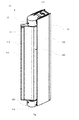
Fig. 1 is an isometric view of an assembly for receiving a shower door according to an embodiment; -
Figs. 2a-c are exploded views of an assembly for receiving a shower door comprising a fixation device according to an embodiment; -
Fig. 3a-b are A-A section views of a door stop structure according to an embodiment; -
Figs. 4a-b are B-B section views of a door stop structure according to an embodiment; -
Fig. 5 is a top view of a shower door system according to an embodiment; -
Fig. 6 is a top view of a shower door system according to an embodiment; and -
Fig. 7 is a top view of a shower door system according to an embodiment. - Starting with
Fig. 1 , anassembly 10 for receiving a shower door in a shower compartment is shown. Theassembly 10 comprises adoor stop structure 11 securely attached to awall support 13 by at least onefixation device 14. Thewall support 13 is securely attached to the wall e.g. by means of screws or similar. Thedoor stop structure 11 comprises astop member 110, ahinge 120 and ahinge support 130. Thehinge 120 is extending vertically along the length of thewall support 13 and thestop member 110 extends along the length of thehinge 120. - In one embodiment the
hinge 120 comprises twosupport members 121 arranged at the upper and lower end of thehinge support 130, respectively. Thesupport members 121 are arranged to rotationally support thestop member 110. - A
stop surface 111 is provided at an outer end of thestop member 110. Thestop surface 111 is in the form of a protrusion extending radially out from thehinge 120; the axial length of thestop surface 111 is preferably the same as the axial extension of thehinge 120 or even slightly larger such that thestop surface 111 extends down to the floor. When theassembly 10 is arranged in a fully installed shower compartment, thestop surface 111 will form a rotational stop of an associated shower door, as will be described more in detail with reference tofigures 5-7 . - During installation it is beneficial to be able to rotate the
door stop structure 11 relative a bathroom wall in order to angle adjust theassembly 10. This is possible since thestop member 110 is pivotable attached relative thewall support 13. Furthermore, thehinge 120 allows thestop member 110 to pivot around a vertical axis relative thehinge support 130. Hence, an easy angle adjustment of thehinge 120 is provided. - After the
assembly 10 is installed, the angular position of thestop member 110 is locked. In order to unlock and/or lock the angular position of thestop member 110, locking means 112 are provided. This allows for an easy angle adjustment. The locking means 112 will be described more in detail with reference tofigure 2b . - Now turning to
figures 2a-c , exploded views of an embodiment of anassembly 10 is shown. Infigure 2a ahinge 120 is shown with astop member 110 and a stop surface 111.At least one of the longitudinal ends of thestop member 110 are arranged with aprotrusion 119. The at least oneprotrusion 119 slidably engages with a corresponding receiving section 122 (seefigure 2b ) of thesupport member 121. In one embodiment as shown infigure 2a , each longitudinal end of thestop member 110 is arranged with oneprotrusion 119 having at least one hole on the stop surface. - A
disc 118 is rigidly arranged onto the top of theprotrusion 119 and has a shape corresponding to the top of theprotrusion 119 facing the receivingsection 120 of thesupport member 121. Eachdisc 118 is arranged with at least one through hole corresponding to the holes in theprotrusion 119. The discs are preferably constructed by a metal such as aluminum. Although the discs in the embodiment shown infigure 2 each have two holes, any number of through holes is possible. -
Figure 2b shows an exploded view of ahinge support 130 and twosupport members 121, arranged at each end of thehinge support 130. Eachsupport member 121 comprises ahousing 123, a receivingsection 122, at least oneadjustment screw 114 and locking means 112. The receivingsection 122 is inserted into thehousing 123 and fixated with anadjustment screw 114 which attaches with thewall structure 13 via thefixation device 14. - During installation of the
assembly 10 the locking means 112 may be unlocked in order to adjust the angular position of thestop member 110. The locking means 112 comprises at least one lockingscrew 116 and at least one corresponding throughhole 117. The at least one throughhole 117 is provided in a lower part and/or an upper part of thehinge 120. - In the embodiment shown in
figure 2 , two locking means 112 are provided at the longitudinal ends of thehinge 120 and each locking means 112 comprises two lockingscrews 116 with two corresponding throughholes 117; however the exact number of locking means 112, lockingscrews 116 and throughholes 117 may vary depending on the size and construction of thewall support 13 and/ordoor stop structure 11. - The locking means 112 is unlocked by simply loosening the locking screws 116, also referred to as stop screws. A step less angle adjustment of the assembly is thereafter achieved by adjusting the
stop member 110 in relation to thehinge 120 by simply pushing or pulling thestop member 110 into a desirable position. Once the desirable angle is reached, the locking means 112 is locked by tightening the locking screws 116 in the throughholes 117. - In
figure 2c , an isometric view of awall support 13 comprising at least onefixation device 14 is shown. Fixation of thedoor stop structure 11 to thewall support 13 is achieved by means of at least onefixation device 14. Onefixation device 14 is arranged at the respective vertical end of thewall support 13. Thefixation device 14 is configured to receive theattachment screw 114 of thedoor stop structure 11, and to fixate the position of theattachment screw 114. In the embodiment shown infigure 2 , twofixation devices 14 are provided at each longitudinal ends of thewall support 13; however the exact number offixation devices 14 may vary depending on the size and construction of thewall support 13 and/or thedoor stop structure 11. The attachment screw may be abolt 114. - The
fixation devices 14 are attached to thewall support 13 by inserting them into associated cavities inside thesupport 13. In one embodiment the longitudinal ends of thesupport 13 are open so that thefixation devices 14 can be inserted. Ridges or similar structures may be provided inside thehollow support 13 such that thefixation devices 14 will be prevented from moving further into thesupport 13. Preferably, thefixation devices 14 may only be inserted in a specific orientation.Lids 142 may further be provided for covering the ends of thesupport 13 once thefixation devices 14 have been inserted. Thelids 142 are both providing a cover for the longitudinal end of thewall support 13, but also safety functionality for thefixation device 14. - Each
fixation device 14 has a recess, or bore 141 for receiving abolt 114 of thedoor stop structure 11. Thebolt 114 is preferably extending through thehinge 120 such that it may be operated from a side of thehinge 120 being opposite the side facing thewall support 13. Thefixation device 14 thus allows for a rigid and robust fixation of thedoor stop structure 11 relative thewall support 13. - The
fixation device 14 is attached to thewall support 13. Upon assembly of thedoor stop structure 11, i.e. the door stop structure 11 (including the bolt(s) 114) is pressed against thewall support 13 such that the bolt(s) 114 are received in the bore of thefixation device 14. After tightening thebolts 114, which also provides an adjustment of the vertical alignment of thedoor stop structure 11, thedoor stop structure 11 is securely attached to thewall support 13, and hence the wall. - In one embodiment, the
fixation device 14, also referred to as a quick lock assembly, has the design and functionality as described by the embodiments in the EP-application with filing no. 14187815.7 filed by the same applicant. -
Figs. 3A-B and 4A-B show cross-sectional top views of theassembly 10. As can be seen, thebolt 114 is accessible only when a through hole of thehinge 120 is aligned correctly, preferably when thestop member 110 is arranged in its end position. - In
Fig. 5 ashower door system 20 is shown comprising ashower door 21 and anassembly 10. Theshower door 21 has ashower door panel 22 which is pivotally supported by awall support 13, preferably being identical with thewall support 13 of theassembly 10. Theshower door panel 22 may be a fixed panel or a door. The slim panel ordoor leaf 22 is preferably being made of a thin body such as glass, plastic, or similar. Theshower door 21 further comprises ahandle 26 which allows the user of the shower to open and close theshower door 21 with ease. Preferably, the handle is a pull handle arranged at theshower door panel 22. - The
shower door panel 21 further comprises adjusting means 23 for setting the lowermost vertical position of theshower door panel 21 at a specific angular position of theshower door panel 21 relative thewall support 13. This may be done by a similar construction as described with respect to theassembly 10, but wherein a cam surface is provided inside the support member of thehinge support 130. The cam surface, or the following surface of thehinge 120, is rotationally fixed, however the other of the cam surface or the following surface may be rotated and secured in a specific angular position for setting a lower most position of theshower door panel 22 at a given angle. This rotate-and-lift functionality is well known, and will not be described further herein. - An
attachment member 24 is arranged at the outer end of theshower door panel 22. Theattachment member 24 may be arranged on or adjacent to thehandle 26 located on theshower door panel 22. In one embodiment as shown infigures 5-7 , the attachment member is amagnetic member 24. Themagnetic member 24 is provided for engagement with amagnetic contact 25 with thedoor stop structure 11 of theassembly 10. Hence, in this embodiment thestop surface 111 of thedoor stop structure 11 is provided with a magnetic contact for magnetically locking thestop member 111 to themagnetic member 24 of theshower door panel 21. - In one embodiment the attachment member is a
lip seal 24. Here, thelip seal 24 is provided for engagement with a lip seal contact of thedoor stop structure 11 of theassembly 10. Hence, in this embodiment thestop surface 111 of thedoor stop structure 11 is provided with a lip seal contact for sealing thestop member 111 to thelip seal 24 of theshower door panel 21. - In
Fig. 5 theassembly 10 and theshower door panel 21 are arranged in a straight manner, i.e. with 0° angle. Hence, in this configuration no angle adjustment of theassembly 10 is required. -
Figs. 6 and7 show ashower door system 20 having an angle, or distance, between theshower door 21 and theassembly 10. InFigs. 6 and7 theshower door system 20 is seen in an exemplified bathroom environment, showing ashower area 1, surroundingwalls 2 and an obstacle such as awindow 3. Thewalls 2 may either be walls of the bathroom or shower panels. - If no obstacle was present, the common way would be to arrange the
shower door system 20 in a straight manner, as indicated by the dotted line. A prior art solution would thus be to arrange theshower system 20 in a straight manner by limiting theshower area 1, as indicated by the dashed line. The present invention solves this problem by the possibility of angel adjustment of theshower system 20. As shown inFigs. 6 and7 , the arrangement of theshower door system 20 is very space efficient. Theshower door 21 is arranged near theobstacle 3 and theassembly 10 is arranged on an opposite wall or wall support. Thedoor stop structure 11 of theassembly 10 is then adjusted to a favorable angle in order to engage with theattachment member 24 of theshower door 21. It would also be possible to change the relative positions of theassembly 10 and theshower door panel 21, as is shown inFig. 7 . - Although the present invention has been described above with reference to specific embodiments, it is not intended to be limited to the specific form set forth herein. Rather, the invention is limited only by the accompanying claims and, other embodiments than the specific above are equally possible within the scope of these appended claims.
Claims (15)
- An assembly (10) for receiving a shower door in a shower compartment, comprising a door stop structure (11), characterized in that the door stop structure (11) comprises a stop member (110) being pivotable relative a wall support (13), and wherein the assembly (10) further comprises locking means (112) for locking the angular position of the stop member (110).
- The assembly according to claim 1, wherein said door stop structure (11) further comprises a hinge (120), to which the stop member (110) is attached, and a hinge support (130).
- The assembly according to claim 2, wherein the hinge (120) is extending vertically along the length of the wall support (13).
- The assembly according to claim 2 or 3, wherein the hinge (120) comprises at least one support member (121) arranged at the upper and/or lower end of the hinge support (130), said support member (121) being configured to rotationally support the stop member (110).
- The assembly according to any one of claims 2-4, wherein the stop member (110) extends along the length of the hinge (120) and comprises a stop surface (111) forming a protrusion extending radially out from the hinge (120).
- The assembly according to claim 5, wherein the stop surface (111) is provided with a magnetic contact for magnetically locking the stop member (110) to a corresponding magnetic stop member of an associated shower door (21).
- The assembly according to any one of the preceding claims, wherein said locking means (112) comprises a through hole (117) and a locking screw (116).
- The assembly according to claim 7, wherein the through hole (117) is provided in a lower part and/or an upper part of the hinge (120).
- The assembly according to any one of the preceding claims, further comprising at least one fixation device (14) for securing said door stop structure (11) to said wall support (13).
- The assembly according to any one of the preceding claims, wherein said at least one fixation device (14) is configured to allow for an adjustment of the door stop structure (11) relative a vertical direction.
- The assembly according to claim 9 or 10, wherein said fixation device (14) is configured to receive a bolt (114) of the door stop structure (11), and to fixate the position of the bolt (114).
- The assembly according to claim 11, wherein one fixation device (14) is arranged at the respective vertical end of the wall support (13).
- A shower door system, comprising a shower door (21) having a shower door panel (22) being pivotally supported by a wall support (13), and an assembly (10) according to any one of the preceding claims.
- The shower door system according to claim 13, wherein the shower door (21) comprises means for moving the shower door panel (22) upwards during opening of the shower door (21), and moving the shower door panel (22) downwards during closing of the door (21).
- The shower door system according to claim 14, wherein the shower door panel (22) further comprising adjusting means (23) for setting the lowermost vertical position of the shower door panel (22) at a specific angular position of the shower door panel (22) relative the wall support (13).
Priority Applications (6)
| Application Number | Priority Date | Filing Date | Title |
|---|---|---|---|
| PL15158247T PL3067503T3 (en) | 2015-03-09 | 2015-03-09 | Shower door system, and assembly therefor |
| DK15158247.5T DK3067503T3 (en) | 2015-03-09 | 2015-03-09 | SHOWER DOOR SYSTEM AND COLLECTION THEREOF |
| EP15158247.5A EP3067503B1 (en) | 2015-03-09 | 2015-03-09 | Shower door system, and assembly therefor |
| RU2016107795A RU2713145C2 (en) | 2015-03-09 | 2016-03-03 | Shower door system and assembly therefor |
| UAA201602092A UA122559C2 (en) | 2015-03-09 | 2016-03-03 | SHOWER DOOR SYSTEM AND ASSEMBLY FOR IT |
| CN201610132949.6A CN105952292B (en) | 2015-03-09 | 2016-03-09 | Take a shower door system and its component |
Applications Claiming Priority (1)
| Application Number | Priority Date | Filing Date | Title |
|---|---|---|---|
| EP15158247.5A EP3067503B1 (en) | 2015-03-09 | 2015-03-09 | Shower door system, and assembly therefor |
Publications (2)
| Publication Number | Publication Date |
|---|---|
| EP3067503A1 true EP3067503A1 (en) | 2016-09-14 |
| EP3067503B1 EP3067503B1 (en) | 2019-12-18 |
Family
ID=52627126
Family Applications (1)
| Application Number | Title | Priority Date | Filing Date |
|---|---|---|---|
| EP15158247.5A Active EP3067503B1 (en) | 2015-03-09 | 2015-03-09 | Shower door system, and assembly therefor |
Country Status (6)
| Country | Link |
|---|---|
| EP (1) | EP3067503B1 (en) |
| CN (1) | CN105952292B (en) |
| DK (1) | DK3067503T3 (en) |
| PL (1) | PL3067503T3 (en) |
| RU (1) | RU2713145C2 (en) |
| UA (1) | UA122559C2 (en) |
Families Citing this family (1)
| Publication number | Priority date | Publication date | Assignee | Title |
|---|---|---|---|---|
| CN114183026A (en) * | 2021-12-22 | 2022-03-15 | 中山市福瑞卫浴设备有限公司 | Shower room door hinge mounting structure and shower room door |
Citations (3)
| Publication number | Priority date | Publication date | Assignee | Title |
|---|---|---|---|---|
| DE1932154A1 (en) * | 1969-06-25 | 1971-01-07 | Simon Fa Karl | Magnetic holding device |
| US3553891A (en) * | 1968-10-24 | 1971-01-12 | Sunset Ind Inc | Adjustable doorjamb |
| US5480199A (en) * | 1994-01-18 | 1996-01-02 | Kohler Co. | Door latching and seal assembly |
Family Cites Families (7)
| Publication number | Priority date | Publication date | Assignee | Title |
|---|---|---|---|---|
| SE523996C2 (en) * | 2000-12-15 | 2004-06-15 | Glasmaesteribranschens Service | Device on a hinge |
| US6701672B2 (en) * | 2001-04-30 | 2004-03-09 | Kohler Co. | Compression mounting system for shower doors |
| CN2926398Y (en) * | 2006-07-31 | 2007-07-25 | 中山市莎丽卫浴设备有限公司 | A frameless sliding door shower room |
| DK1932991T3 (en) * | 2006-12-15 | 2010-08-02 | Inredningsglas Skandinavien Ab | Hinge |
| CN201891335U (en) * | 2010-10-29 | 2011-07-06 | 比亚迪股份有限公司 | Door closing stop device |
| CN202500419U (en) * | 2012-02-27 | 2012-10-24 | 胡海明 | Adjustable limiting hinge |
| CN202544647U (en) * | 2012-03-27 | 2012-11-21 | 张邵明 | Hinge rotating shaft door of glass shower room |
-
2015
- 2015-03-09 PL PL15158247T patent/PL3067503T3/en unknown
- 2015-03-09 EP EP15158247.5A patent/EP3067503B1/en active Active
- 2015-03-09 DK DK15158247.5T patent/DK3067503T3/en active
-
2016
- 2016-03-03 RU RU2016107795A patent/RU2713145C2/en active
- 2016-03-03 UA UAA201602092A patent/UA122559C2/en unknown
- 2016-03-09 CN CN201610132949.6A patent/CN105952292B/en not_active Expired - Fee Related
Patent Citations (3)
| Publication number | Priority date | Publication date | Assignee | Title |
|---|---|---|---|---|
| US3553891A (en) * | 1968-10-24 | 1971-01-12 | Sunset Ind Inc | Adjustable doorjamb |
| DE1932154A1 (en) * | 1969-06-25 | 1971-01-07 | Simon Fa Karl | Magnetic holding device |
| US5480199A (en) * | 1994-01-18 | 1996-01-02 | Kohler Co. | Door latching and seal assembly |
Also Published As
| Publication number | Publication date |
|---|---|
| DK3067503T3 (en) | 2020-03-23 |
| EP3067503B1 (en) | 2019-12-18 |
| PL3067503T3 (en) | 2020-06-01 |
| RU2016107795A3 (en) | 2019-05-22 |
| UA122559C2 (en) | 2020-12-10 |
| CN105952292B (en) | 2019-08-06 |
| RU2713145C2 (en) | 2020-02-03 |
| RU2016107795A (en) | 2017-09-07 |
| CN105952292A (en) | 2016-09-21 |
Similar Documents
| Publication | Publication Date | Title |
|---|---|---|
| RU2546489C2 (en) | Door block | |
| EP3075940B1 (en) | Corner connection device of shower door track, shower door frame and shower door | |
| RU2566258C2 (en) | Door module | |
| EP3085874B1 (en) | Connection device and shower door component having same | |
| US11891847B2 (en) | Compact sliding door system with soft-close and locking functionality | |
| GB2440605A (en) | Hidden adjustable fixing system for screen | |
| EP2859829A1 (en) | Door assembly | |
| EP3321458B1 (en) | A hinge arrangement, in particular a hidden hinge arrangement | |
| EP3067503B1 (en) | Shower door system, and assembly therefor | |
| IE86891B1 (en) | Hinge for a door or the like | |
| CN102482903A (en) | Mechanisms for mounting doors or other similar closures with rotational and translational movement | |
| EP1932991B1 (en) | Hinge | |
| EP1746921B1 (en) | Hinge | |
| KR102072149B1 (en) | Lower roller assembly of triple sliding interlocking door | |
| EP3004486B1 (en) | A building system and a bracket for such building system | |
| EP3005919B1 (en) | A fixation device for a shower door system | |
| CA3129666A1 (en) | Hinge lock | |
| US20200048900A1 (en) | Door for a Partition Wall, and Partition Wall | |
| WO2014202094A1 (en) | Hinge and lock for a sash in a building element | |
| US6925683B2 (en) | Hinge | |
| US20120198657A1 (en) | Pivot Sliding Hinge | |
| JP2003148028A (en) | Swing-door opening-angle adjusting structure | |
| WO2018199741A2 (en) | Wall element for a partition wall, and partition wall |
Legal Events
| Date | Code | Title | Description |
|---|---|---|---|
| PUAI | Public reference made under article 153(3) epc to a published international application that has entered the european phase |
Free format text: ORIGINAL CODE: 0009012 |
|
| AK | Designated contracting states |
Kind code of ref document: A1 Designated state(s): AL AT BE BG CH CY CZ DE DK EE ES FI FR GB GR HR HU IE IS IT LI LT LU LV MC MK MT NL NO PL PT RO RS SE SI SK SM TR |
|
| AX | Request for extension of the european patent |
Extension state: BA ME |
|
| RAP1 | Party data changed (applicant data changed or rights of an application transferred) |
Owner name: GEBERIT INTERNATIONAL AG |
|
| STAA | Information on the status of an ep patent application or granted ep patent |
Free format text: STATUS: REQUEST FOR EXAMINATION WAS MADE |
|
| 17P | Request for examination filed |
Effective date: 20170314 |
|
| RBV | Designated contracting states (corrected) |
Designated state(s): AL AT BE BG CH CY CZ DE DK EE ES FI FR GB GR HR HU IE IS IT LI LT LU LV MC MK MT NL NO PL PT RO RS SE SI SK SM TR |
|
| GRAP | Despatch of communication of intention to grant a patent |
Free format text: ORIGINAL CODE: EPIDOSNIGR1 |
|
| STAA | Information on the status of an ep patent application or granted ep patent |
Free format text: STATUS: GRANT OF PATENT IS INTENDED |
|
| INTG | Intention to grant announced |
Effective date: 20190711 |
|
| GRAS | Grant fee paid |
Free format text: ORIGINAL CODE: EPIDOSNIGR3 |
|
| GRAA | (expected) grant |
Free format text: ORIGINAL CODE: 0009210 |
|
| STAA | Information on the status of an ep patent application or granted ep patent |
Free format text: STATUS: THE PATENT HAS BEEN GRANTED |
|
| AK | Designated contracting states |
Kind code of ref document: B1 Designated state(s): AL AT BE BG CH CY CZ DE DK EE ES FI FR GB GR HR HU IE IS IT LI LT LU LV MC MK MT NL NO PL PT RO RS SE SI SK SM TR |
|
| REG | Reference to a national code |
Ref country code: CH Ref legal event code: EP |
|
| REG | Reference to a national code |
Ref country code: IE Ref legal event code: FG4D |
|
| REG | Reference to a national code |
Ref country code: DE Ref legal event code: R096 Ref document number: 602015043710 Country of ref document: DE |
|
| REG | Reference to a national code |
Ref country code: AT Ref legal event code: REF Ref document number: 1214771 Country of ref document: AT Kind code of ref document: T Effective date: 20200115 |
|
| REG | Reference to a national code |
Ref country code: FI Ref legal event code: FGE |
|
| REG | Reference to a national code |
Ref country code: DK Ref legal event code: T3 Effective date: 20200318 |
|
| REG | Reference to a national code |
Ref country code: SE Ref legal event code: TRGR |
|
| REG | Reference to a national code |
Ref country code: NL Ref legal event code: MP Effective date: 20191218 |
|
| PG25 | Lapsed in a contracting state [announced via postgrant information from national office to epo] |
Ref country code: LV Free format text: LAPSE BECAUSE OF FAILURE TO SUBMIT A TRANSLATION OF THE DESCRIPTION OR TO PAY THE FEE WITHIN THE PRESCRIBED TIME-LIMIT Effective date: 20191218 Ref country code: GR Free format text: LAPSE BECAUSE OF FAILURE TO SUBMIT A TRANSLATION OF THE DESCRIPTION OR TO PAY THE FEE WITHIN THE PRESCRIBED TIME-LIMIT Effective date: 20200319 Ref country code: LT Free format text: LAPSE BECAUSE OF FAILURE TO SUBMIT A TRANSLATION OF THE DESCRIPTION OR TO PAY THE FEE WITHIN THE PRESCRIBED TIME-LIMIT Effective date: 20191218 Ref country code: BG Free format text: LAPSE BECAUSE OF FAILURE TO SUBMIT A TRANSLATION OF THE DESCRIPTION OR TO PAY THE FEE WITHIN THE PRESCRIBED TIME-LIMIT Effective date: 20200318 |
|
| REG | Reference to a national code |
Ref country code: NO Ref legal event code: T2 Effective date: 20191218 |
|
| REG | Reference to a national code |
Ref country code: LT Ref legal event code: MG4D |
|
| PG25 | Lapsed in a contracting state [announced via postgrant information from national office to epo] |
Ref country code: RS Free format text: LAPSE BECAUSE OF FAILURE TO SUBMIT A TRANSLATION OF THE DESCRIPTION OR TO PAY THE FEE WITHIN THE PRESCRIBED TIME-LIMIT Effective date: 20191218 Ref country code: HR Free format text: LAPSE BECAUSE OF FAILURE TO SUBMIT A TRANSLATION OF THE DESCRIPTION OR TO PAY THE FEE WITHIN THE PRESCRIBED TIME-LIMIT Effective date: 20191218 |
|
| PG25 | Lapsed in a contracting state [announced via postgrant information from national office to epo] |
Ref country code: AL Free format text: LAPSE BECAUSE OF FAILURE TO SUBMIT A TRANSLATION OF THE DESCRIPTION OR TO PAY THE FEE WITHIN THE PRESCRIBED TIME-LIMIT Effective date: 20191218 |
|
| PG25 | Lapsed in a contracting state [announced via postgrant information from national office to epo] |
Ref country code: EE Free format text: LAPSE BECAUSE OF FAILURE TO SUBMIT A TRANSLATION OF THE DESCRIPTION OR TO PAY THE FEE WITHIN THE PRESCRIBED TIME-LIMIT Effective date: 20191218 Ref country code: PT Free format text: LAPSE BECAUSE OF FAILURE TO SUBMIT A TRANSLATION OF THE DESCRIPTION OR TO PAY THE FEE WITHIN THE PRESCRIBED TIME-LIMIT Effective date: 20200513 Ref country code: RO Free format text: LAPSE BECAUSE OF FAILURE TO SUBMIT A TRANSLATION OF THE DESCRIPTION OR TO PAY THE FEE WITHIN THE PRESCRIBED TIME-LIMIT Effective date: 20191218 Ref country code: NL Free format text: LAPSE BECAUSE OF FAILURE TO SUBMIT A TRANSLATION OF THE DESCRIPTION OR TO PAY THE FEE WITHIN THE PRESCRIBED TIME-LIMIT Effective date: 20191218 Ref country code: CZ Free format text: LAPSE BECAUSE OF FAILURE TO SUBMIT A TRANSLATION OF THE DESCRIPTION OR TO PAY THE FEE WITHIN THE PRESCRIBED TIME-LIMIT Effective date: 20191218 |
|
| PG25 | Lapsed in a contracting state [announced via postgrant information from national office to epo] |
Ref country code: SM Free format text: LAPSE BECAUSE OF FAILURE TO SUBMIT A TRANSLATION OF THE DESCRIPTION OR TO PAY THE FEE WITHIN THE PRESCRIBED TIME-LIMIT Effective date: 20191218 Ref country code: SK Free format text: LAPSE BECAUSE OF FAILURE TO SUBMIT A TRANSLATION OF THE DESCRIPTION OR TO PAY THE FEE WITHIN THE PRESCRIBED TIME-LIMIT Effective date: 20191218 Ref country code: IS Free format text: LAPSE BECAUSE OF FAILURE TO SUBMIT A TRANSLATION OF THE DESCRIPTION OR TO PAY THE FEE WITHIN THE PRESCRIBED TIME-LIMIT Effective date: 20200418 |
|
| REG | Reference to a national code |
Ref country code: DE Ref legal event code: R097 Ref document number: 602015043710 Country of ref document: DE |
|
| REG | Reference to a national code |
Ref country code: AT Ref legal event code: MK05 Ref document number: 1214771 Country of ref document: AT Kind code of ref document: T Effective date: 20191218 |
|
| PLBE | No opposition filed within time limit |
Free format text: ORIGINAL CODE: 0009261 |
|
| STAA | Information on the status of an ep patent application or granted ep patent |
Free format text: STATUS: NO OPPOSITION FILED WITHIN TIME LIMIT |
|
| PG25 | Lapsed in a contracting state [announced via postgrant information from national office to epo] |
Ref country code: MC Free format text: LAPSE BECAUSE OF FAILURE TO SUBMIT A TRANSLATION OF THE DESCRIPTION OR TO PAY THE FEE WITHIN THE PRESCRIBED TIME-LIMIT Effective date: 20191218 Ref country code: ES Free format text: LAPSE BECAUSE OF FAILURE TO SUBMIT A TRANSLATION OF THE DESCRIPTION OR TO PAY THE FEE WITHIN THE PRESCRIBED TIME-LIMIT Effective date: 20191218 |
|
| REG | Reference to a national code |
Ref country code: CH Ref legal event code: PL |
|
| 26N | No opposition filed |
Effective date: 20200921 |
|
| PG25 | Lapsed in a contracting state [announced via postgrant information from national office to epo] |
Ref country code: AT Free format text: LAPSE BECAUSE OF FAILURE TO SUBMIT A TRANSLATION OF THE DESCRIPTION OR TO PAY THE FEE WITHIN THE PRESCRIBED TIME-LIMIT Effective date: 20191218 Ref country code: SI Free format text: LAPSE BECAUSE OF FAILURE TO SUBMIT A TRANSLATION OF THE DESCRIPTION OR TO PAY THE FEE WITHIN THE PRESCRIBED TIME-LIMIT Effective date: 20191218 |
|
| REG | Reference to a national code |
Ref country code: BE Ref legal event code: MM Effective date: 20200331 |
|
| PG25 | Lapsed in a contracting state [announced via postgrant information from national office to epo] |
Ref country code: LU Free format text: LAPSE BECAUSE OF NON-PAYMENT OF DUE FEES Effective date: 20200309 |
|
| PG25 | Lapsed in a contracting state [announced via postgrant information from national office to epo] |
Ref country code: IE Free format text: LAPSE BECAUSE OF NON-PAYMENT OF DUE FEES Effective date: 20200309 Ref country code: LI Free format text: LAPSE BECAUSE OF NON-PAYMENT OF DUE FEES Effective date: 20200331 Ref country code: IT Free format text: LAPSE BECAUSE OF FAILURE TO SUBMIT A TRANSLATION OF THE DESCRIPTION OR TO PAY THE FEE WITHIN THE PRESCRIBED TIME-LIMIT Effective date: 20191218 Ref country code: CH Free format text: LAPSE BECAUSE OF NON-PAYMENT OF DUE FEES Effective date: 20200331 |
|
| PG25 | Lapsed in a contracting state [announced via postgrant information from national office to epo] |
Ref country code: BE Free format text: LAPSE BECAUSE OF NON-PAYMENT OF DUE FEES Effective date: 20200331 |
|
| PGFP | Annual fee paid to national office [announced via postgrant information from national office to epo] |
Ref country code: DE Payment date: 20210319 Year of fee payment: 7 Ref country code: PL Payment date: 20210208 Year of fee payment: 7 Ref country code: GB Payment date: 20210312 Year of fee payment: 7 |
|
| PG25 | Lapsed in a contracting state [announced via postgrant information from national office to epo] |
Ref country code: TR Free format text: LAPSE BECAUSE OF FAILURE TO SUBMIT A TRANSLATION OF THE DESCRIPTION OR TO PAY THE FEE WITHIN THE PRESCRIBED TIME-LIMIT Effective date: 20191218 Ref country code: MT Free format text: LAPSE BECAUSE OF FAILURE TO SUBMIT A TRANSLATION OF THE DESCRIPTION OR TO PAY THE FEE WITHIN THE PRESCRIBED TIME-LIMIT Effective date: 20191218 Ref country code: CY Free format text: LAPSE BECAUSE OF FAILURE TO SUBMIT A TRANSLATION OF THE DESCRIPTION OR TO PAY THE FEE WITHIN THE PRESCRIBED TIME-LIMIT Effective date: 20191218 |
|
| PG25 | Lapsed in a contracting state [announced via postgrant information from national office to epo] |
Ref country code: MK Free format text: LAPSE BECAUSE OF FAILURE TO SUBMIT A TRANSLATION OF THE DESCRIPTION OR TO PAY THE FEE WITHIN THE PRESCRIBED TIME-LIMIT Effective date: 20191218 |
|
| PG25 | Lapsed in a contracting state [announced via postgrant information from national office to epo] |
Ref country code: FR Free format text: LAPSE BECAUSE OF NON-PAYMENT OF DUE FEES Effective date: 20200331 |
|
| REG | Reference to a national code |
Ref country code: DE Ref legal event code: R119 Ref document number: 602015043710 Country of ref document: DE |
|
| GBPC | Gb: european patent ceased through non-payment of renewal fee |
Effective date: 20220309 |
|
| PG25 | Lapsed in a contracting state [announced via postgrant information from national office to epo] |
Ref country code: GB Free format text: LAPSE BECAUSE OF NON-PAYMENT OF DUE FEES Effective date: 20220309 Ref country code: DE Free format text: LAPSE BECAUSE OF NON-PAYMENT OF DUE FEES Effective date: 20221001 |
|
| P01 | Opt-out of the competence of the unified patent court (upc) registered |
Effective date: 20230527 |
|
| PG25 | Lapsed in a contracting state [announced via postgrant information from national office to epo] |
Ref country code: PL Free format text: LAPSE BECAUSE OF NON-PAYMENT OF DUE FEES Effective date: 20220309 |
|
| REG | Reference to a national code |
Ref country code: FI Ref legal event code: PCE Owner name: CONTURA SHOWER AB |
|
| PGFP | Annual fee paid to national office [announced via postgrant information from national office to epo] |
Ref country code: SE Payment date: 20260317 Year of fee payment: 12 |
|
| PGFP | Annual fee paid to national office [announced via postgrant information from national office to epo] |
Ref country code: NO Payment date: 20260312 Year of fee payment: 12 Ref country code: DK Payment date: 20260311 Year of fee payment: 12 |
|
| PGFP | Annual fee paid to national office [announced via postgrant information from national office to epo] |
Ref country code: FI Payment date: 20260310 Year of fee payment: 12 |