EP3067190A1 - Method for cutting belt-like member, and apparatus therefor - Google Patents
Method for cutting belt-like member, and apparatus therefor Download PDFInfo
- Publication number
- EP3067190A1 EP3067190A1 EP14860227.9A EP14860227A EP3067190A1 EP 3067190 A1 EP3067190 A1 EP 3067190A1 EP 14860227 A EP14860227 A EP 14860227A EP 3067190 A1 EP3067190 A1 EP 3067190A1
- Authority
- EP
- European Patent Office
- Prior art keywords
- belt
- reinforcement
- cutting
- reinforcement cords
- cord
- Prior art date
- Legal status (The legal status is an assumption and is not a legal conclusion. Google has not performed a legal analysis and makes no representation as to the accuracy of the status listed.)
- Granted
Links
- 238000005520 cutting process Methods 0.000 title claims abstract description 191
- 238000000034 method Methods 0.000 title claims description 31
- 230000002787 reinforcement Effects 0.000 claims abstract description 291
- 238000004519 manufacturing process Methods 0.000 claims abstract description 16
- 238000001514 detection method Methods 0.000 claims description 92
- 238000009826 distribution Methods 0.000 claims description 10
- 238000010586 diagram Methods 0.000 description 10
- 238000004804 winding Methods 0.000 description 4
- 230000000694 effects Effects 0.000 description 3
- 238000005516 engineering process Methods 0.000 description 3
- 238000006073 displacement reaction Methods 0.000 description 2
- 238000005304 joining Methods 0.000 description 2
- 230000002093 peripheral effect Effects 0.000 description 2
- 230000005855 radiation Effects 0.000 description 2
- 238000011144 upstream manufacturing Methods 0.000 description 2
- 238000012935 Averaging Methods 0.000 description 1
- 239000004677 Nylon Substances 0.000 description 1
- 101100088247 Picea mariana RPL13A gene Proteins 0.000 description 1
- 230000003213 activating effect Effects 0.000 description 1
- 238000004364 calculation method Methods 0.000 description 1
- 239000000284 extract Substances 0.000 description 1
- 239000000835 fiber Substances 0.000 description 1
- 230000001678 irradiating effect Effects 0.000 description 1
- 239000000463 material Substances 0.000 description 1
- 239000002184 metal Substances 0.000 description 1
- 229920001778 nylon Polymers 0.000 description 1
- 229920000728 polyester Polymers 0.000 description 1
Images





Classifications
-
- B—PERFORMING OPERATIONS; TRANSPORTING
- B29—WORKING OF PLASTICS; WORKING OF SUBSTANCES IN A PLASTIC STATE IN GENERAL
- B29D—PRODUCING PARTICULAR ARTICLES FROM PLASTICS OR FROM SUBSTANCES IN A PLASTIC STATE
- B29D30/00—Producing pneumatic or solid tyres or parts thereof
- B29D30/06—Pneumatic tyres or parts thereof (e.g. produced by casting, moulding, compression moulding, injection moulding, centrifugal casting)
- B29D30/38—Textile inserts, e.g. cord or canvas layers, for tyres; Treatment of inserts prior to building the tyre
- B29D30/46—Cutting textile inserts to required shape
-
- B—PERFORMING OPERATIONS; TRANSPORTING
- B26—HAND CUTTING TOOLS; CUTTING; SEVERING
- B26D—CUTTING; DETAILS COMMON TO MACHINES FOR PERFORATING, PUNCHING, CUTTING-OUT, STAMPING-OUT OR SEVERING
- B26D1/00—Cutting through work characterised by the nature or movement of the cutting member or particular materials not otherwise provided for; Apparatus or machines therefor; Cutting members therefor
- B26D1/0006—Cutting members therefor
-
- B—PERFORMING OPERATIONS; TRANSPORTING
- B26—HAND CUTTING TOOLS; CUTTING; SEVERING
- B26D—CUTTING; DETAILS COMMON TO MACHINES FOR PERFORATING, PUNCHING, CUTTING-OUT, STAMPING-OUT OR SEVERING
- B26D5/00—Arrangements for operating and controlling machines or devices for cutting, cutting-out, stamping-out, punching, perforating, or severing by means other than cutting
- B26D5/007—Control means comprising cameras, vision or image processing systems
-
- B—PERFORMING OPERATIONS; TRANSPORTING
- B29—WORKING OF PLASTICS; WORKING OF SUBSTANCES IN A PLASTIC STATE IN GENERAL
- B29D—PRODUCING PARTICULAR ARTICLES FROM PLASTICS OR FROM SUBSTANCES IN A PLASTIC STATE
- B29D30/00—Producing pneumatic or solid tyres or parts thereof
- B29D30/06—Pneumatic tyres or parts thereof (e.g. produced by casting, moulding, compression moulding, injection moulding, centrifugal casting)
- B29D30/38—Textile inserts, e.g. cord or canvas layers, for tyres; Treatment of inserts prior to building the tyre
- B29D30/46—Cutting textile inserts to required shape
- B29D2030/466—Cutting the textile inserts between cords
-
- Y—GENERAL TAGGING OF NEW TECHNOLOGICAL DEVELOPMENTS; GENERAL TAGGING OF CROSS-SECTIONAL TECHNOLOGIES SPANNING OVER SEVERAL SECTIONS OF THE IPC; TECHNICAL SUBJECTS COVERED BY FORMER USPC CROSS-REFERENCE ART COLLECTIONS [XRACs] AND DIGESTS
- Y10—TECHNICAL SUBJECTS COVERED BY FORMER USPC
- Y10S—TECHNICAL SUBJECTS COVERED BY FORMER USPC CROSS-REFERENCE ART COLLECTIONS [XRACs] AND DIGESTS
- Y10S83/00—Cutting
- Y10S83/929—Particular nature of work or product
- Y10S83/951—Rubber tyre
-
- Y—GENERAL TAGGING OF NEW TECHNOLOGICAL DEVELOPMENTS; GENERAL TAGGING OF CROSS-SECTIONAL TECHNOLOGIES SPANNING OVER SEVERAL SECTIONS OF THE IPC; TECHNICAL SUBJECTS COVERED BY FORMER USPC CROSS-REFERENCE ART COLLECTIONS [XRACs] AND DIGESTS
- Y10—TECHNICAL SUBJECTS COVERED BY FORMER USPC
- Y10T—TECHNICAL SUBJECTS COVERED BY FORMER US CLASSIFICATION
- Y10T83/00—Cutting
- Y10T83/525—Operation controlled by detector means responsive to work
- Y10T83/538—Positioning of tool controlled
Definitions
- the present invention relates to a method for cutting a belt-like member having embedded therein a plurality of reinforcement cords arranged parallel to each other, along the reinforcement cords, and an apparatus therefor.
- a strip member is sometimes wound onto the outer peripheral surface of a belt member.
- the strip member is obtained by cutting a belt-like member having embedded therein a plurality of reinforcement cords arranged parallel to each other, along the reinforcement cords.
- a method for cutting this belt-like member a method is known in which, as well as irradiating electromagnetic wave radiation, such as X rays or gamma rays, onto the belt-like member having embedded therein the plurality of reinforcement cords arranged parallel to each other, and detecting an embedded position of each of the reinforcement cords on the basis of energy of the electromagnetic wave radiation dispersed by the belt-like member, a cutting position of the belt-like member is determined on the basis of the detection results (Patent Document 1).
- electromagnetic wave radiation such as X rays or gamma rays
- a jointless strip member is sometimes wound onto the belt member.
- a method and an apparatus are known in which, instead of cutting a belt-like member at a constant width, the number of the reinforcement cords of the belt-like member is counted using image processing before the strip member is manufactured, and the cutting is performed at a constant number of the reinforcement cords (Patent Document 2).
- a weft thread another type of cord
- it is known that another type of cord hereinafter referred to as a weft thread
- a weft thread another type of cord
- an image pick-up device performs image capture of cutting means capable of moving in a width direction of the belt-like member, as well as of a portion of the belt-like member including a first end in the width direction at one end in the length direction of the belt-like member (hereinafter, this end is referred to as a downstream side end). Additionally, on a captured image captured by the image pick-up device, a position of each of the reinforcement cords appearing at the downstream side end in the length direction of the belt-like member and a position of the cutting means are detected.
- the cutting means is caused to move in the width direction of the belt-like member toward a second end side on the opposite side to the first end, until the cutting means is arranged in a position, on the captured image, at which the cutting means can perform cutting between the reinforcement cord of a predetermined number from one end side in the width direction of the belt-like member and the next reinforcement cord.
- an image pick-up device stop range is set further to the first end side in the width direction of the belt-like member than the position of the cutting means.
- the cutting means is caused to move toward the second end side on the opposite side to the first end side of the belt-like member, until the detected position of the cutting means on the captured image enters into the image pick-up device stop range.
- the position of each of the reinforcement cords appearing at the downstream side end in the length direction of the belt-like member and the position of the cutting means are detected on the captured image captured by the image pick-up device. Further, using the detection results of the position of each of the reinforcement cords and the position of the cutting means, the cutting means is caused to move toward the second end side of the belt-like member, until the cutting means is arranged in a position at which the cutting means can perform cutting between the reinforcement cord of a predetermined number from the position at which the immediately preceding cut has been made and the next reinforcement cord, on the captured image.
- an object of the present invention is to provide a method for cutting a belt-like member, and an apparatus therefor, which enable the strip member formed by cutting the belt-like member to reliably be provided with a desired number of the reinforcement cords.
- a first aspect of the present invention is a method for cutting a belt-like member for manufacturing a plurality of strip members by cutting the belt-like member along a length direction of the belt-like member. This cutting method includes the steps of:
- the cutting position be a position between the adjacent reinforcement cords among the reinforcement cords.
- the cutting position be established using a position of the N-th reinforcement cord and the average cord interval Lm.
- the N-th reinforcement cord be the reinforcement cord having the largest number among the plurality of actual numbers smaller than the t-th actual number.
- the cutting position be separated from the position of the N-th reinforcement cord to a side opposite to the first end in the width direction, by Lm ⁇ (t + 1 - N) - Lm ⁇ j (where j is a number greater than 0 and less than 1).
- the position, in the width direction of the belt-like member, of the image of the reinforcement cord be a position of an end portion of the image of the reinforcement cord in the width direction.
- a distribution of an average cord interval for each of locations of the belt-like member be acquired in advance and that, using the distribution, the average cord interval Lm be set corresponding to each of the locations of the belt-like member from which the strip member is to be made.
- the image of the weft thread may also be captured.
- Another aspect of the present invention is a belt-like member cutting apparatus for manufacturing a plurality of strip members by cutting a belt-like member along a length direction of the belt-like member.
- the cutting apparatus has:
- the actual number setting unit sets a sum of the larger detection number and the integer p as the actual number.
- the cutting position determined by the cutting position determining unit be a position between the adjacent reinforcement cords among the reinforcement cords.
- the cutting position determining unit Upon manufacturing the strip member having embedded therein a number t (t is a natural number) of the reinforcement cords, when the cutting position determining unit does not detect the reinforcement cord having the t-th actual number and detects the reinforcement cord having an N-th actual number that is smaller than the t-th actual number, it is preferable that the cutting position be established using a position of the N-th reinforcement cord and the average cord interval Lm.
- the N-th reinforcement cord be the reinforcement cord having the largest number among the plurality of actual numbers smaller than the t-th actual number.
- the cutting position determining unit establish the cutting position as a position separated from the position of the N-th reinforcement cord to a side opposite to the first end in the width direction, by Lm ⁇ (t + 1 - N) - Lm ⁇ j (where j is a number greater than 0 and less than 1).
- the position detecting unit establish, as the position in the width direction of the belt-like member of the image of the reinforcement cord, a position of an end portion in the width direction of the image of the reinforcement cord.
- the actual number setting unit acquire a distribution of an average cord interval for each of locations of the belt-like member in advance and, using the distribution, set the average cord interval Lm corresponding to each of the locations of the belt-like member from which the strip member is to be made.
- the belt-like member cutting apparatus has an image pick-up device capturing, as the captured image, an image also of the weft thread in addition to the images of the reinforcement cords.
- the strip member formed by cutting the belt-like member can be reliably provided with the desired number of reinforcement cords.
- FIGS. 1 to 19 illustrate a present embodiment, where FIG. 1 is a plan view of main parts of a belt-like member cutting apparatus, FIG. 2 is a side view of main parts of the belt-like member cutting apparatus, FIG. 3 is a perspective view illustrating a positional relationship between the belt-like member and an image pick-up device, FIG. 4 is a side view illustrating the positional relationship between the belt-like member and the image pick-up device, FIG. 5 is a block diagram of the belt-like member cutting apparatus, FIG. 6 is a flow chart depicting operations of a control device, FIG. 7 is a schematic view illustrating positional relationships between the image pick-up position, a cutter, and the belt-like member, and FIGS. 8 to 19 are explanatory diagrams of operations of the belt-like member cutting apparatus.
- This belt-like member cutting apparatus has a cutter 10, an image pick-up device 20, a plurality of cutting blades CT, and a plurality of winding rollers RL.
- the cutter 10 is movably provided in a width direction of a belt-like member WB pulled out from a belt-like member wound body.
- the cutter 10 is cutting means capable of forming cuts in a downstream side end in a length direction of the belt-like member WB.
- the image pick-up device 20 is movably provided in the width direction of the belt-like member WB pulled out from the belt-like member wound body.
- the plurality of cutting blades CT are arranged with intervals therebetween in the width direction of the belt-like member WB pulled out from the belt-like member wound body.
- Each of the plurality of winding rollers RL winds up each of strip members SP formed by each of the cutting blades CT passing through the belt-like member WB.
- the belt-like member WB is formed of an unvulcanized rubber material and is formed in a belt shape.
- a thickness dimension thereof is several mm
- a width dimension thereof is substantially 240 mm
- a length dimension thereof is several tens of m.
- reinforcement cords RC are embedded in the belt-like member WB so as to be arranged side by side with each other.
- 240 of the reinforcement cords RC are embedded so as to be arranged substantially parallel to each other, which form a product generally called 70 ends.
- the 70 ends is formed of 70 of the reinforcement cords arranged over a distance of a width of 50 mm.
- Each of the reinforcement cords RC is formed of a metal cord or a rigid fiber cord such as polyester or nylon.
- Each of the reinforcement cords RC is embedded so as to extend in the length direction of the belt-like member WB.
- a cut end surface ES is formed on the downstream side end in the length direction of the belt-like member WB.
- This cut end surface ES is an inclined cross section obtained by diagonally cutting the downstream side end in the length direction of the belt-like member WB, such that the cut end surface ES is oriented to one side in the thickness direction of the belt-like member WB.
- cross sections of each of the reinforcement cords WB appear in the cut end surface ES of the downstream side end in the length direction of the belt-like member WB. Further, as illustrated in FIG.
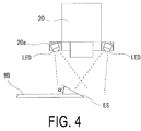
- an angle ⁇ formed by the cut end surface ES and one surface in the thickness direction of the belt-like member be equal to or greater than 30 degrees and equal to or less than 60 degrees.
- the cut end surface ES is cut so as to be within this angle range.
- the cutter 10 has a pair of blades 10a that can be opened and closed in the thickness direction of the belt-like member WB.
- the cutter 10 is supported by a frame 11 provided so as to extend in the width direction of the belt-like member WB.
- the cutter 10 is configured to be moved in the width direction of the belt-like member WB by a width direction movement mechanism 12 provided on the frame 11.
- a length direction movement mechanism 13 which moves the cutter 10 in the length direction of the belt-like member 10, is provided on the frame 11. In this way, in front of the downstream side end in the length direction of the belt-like member WB, the cutter 10 can movably operate in the width direction of the belt-like member WB. In addition, due to the length direction movement mechanism 13, the cutter 10 can move toward an upstream side end in the length direction of the belt-like member WB. In this way, the downstream side end in the length direction of the belt-like member WB is caused to be positioned between each of the blades 10a, and, by closing each of the blades 10a, a cut can be made in the downstream side end in the length direction of the belt-like member WB.
- the image pick-up device 20 is formed by a known CCD camera, for example.
- the image pick-up device 20 is arranged so as to capture an image of the cross section on the downstream side end in the length direction of the belt-like member WB.
- the cross section whose image is captured as described above is the cut end surface ES
- the cut end surface ES is the inclined surface oriented to the one side in the thickness direction of the belt-like member WB.
- the image pick-up device 20 can capture an image of the cut end surface ES as the cross section on the downstream side end in the length direction of the belt-like member WB from the one side in the thickness direction of the belt-like member WB.
- the inclined cut end surface ES is used as the cross section of the downstream side end in the length direction of the belt-like member WB, but the image pick-up device 20 may capture an image of a cross section obtained by cutting the downstream side end in the length direction of the belt-like member WB in the thickness direction.
- a lighting device 20a having a ring shaped frame is attached to the image pick-up device 20, for example, and a plurality of light emitting diodes LED are attached to the bottom surface of the ring shaped frame.
- the lighting device 20a is configured to illuminate the cut end surface ES on the downstream side end in the length direction of the belt-like member WB, from the vicinity of the image pick-up device 20.
- the image pick-up device 20 is supported by a frame 21 provided so as to extend in the width direction of the belt-like member WB, and the image pick-up device 20 is moved in the width direction of the belt-like member WB by a movement mechanism 22 provided on the frame 21.
- the width direction movement mechanism 12, the length direction movement mechanism 13, and the movement mechanism 22 are configured using a servo motor, and a ball screw, for example.
- the cutter 10, the width direction movement mechanism 12, the length direction movement mechanism 13, the image pick-up device 20, and the movement mechanism 22 are connected to a control device 30 configured by a known computer (see FIG. 5 ).
- the control device 30 is configured to detect, for each of the captured images G, positions of each of the reinforcement cords RC appearing in the cut end surface ES on the downstream side end in the length direction of the belt-like member WB, and a position of the blades 10a of the cutter 10.
- the control device 30 is further configured to control the cutter 10, the width direction movement mechanism 12, the length direction movement mechanism 13, the image pick-up device 20, and the movement mechanism 22 on the basis of the positions of each of the reinforcement cords RC and of the blades 10a.
- the control device 30 has a control unit 30a and a processing unit 30b.
- the control unit 30a is configured to control operations of the cutter 10, the width direction movement mechanism 12, the length direction movement mechanism 13, and the movement mechanism 22.
- the processing unit 30b is configured to perform processing on the captured image transmitted from the image pick-up device 20, and determine the cutting position on the belt-like member WB.
- the processing unit 30 has a position detecting unit 30c, an interval calculating unit 30d, an actual number setting unit 30e, and a cutting position determining unit 30f.
- the control device 30 is configured, for example, by a computer having a CPU and a memory.
- the control unit 30a and the processing unit 30b are formed as a software module, by activating a program stored in a memory (not illustrated).
- the control unit 30a, the position detecting unit 30c, the interval calculating unit 30d, the actual number setting unit 30e, and the cutting position determining unit 30f are a software module.
- the position detecting unit 30c performs known image processing on the captured image G of the image pick-up device 20, such as averaging processing, binarization processing, and expansion processing, and thus performs display such that, on the captured image G, only images of each of the reinforcement cords RC and the blades 10a are displayed in white, for example.
- the control device 30 is configured to continuously detect, on the captured image G, a position (a coordinate) P1 of each of the reinforcement cords RC in the width direction of the belt-like member of the downstream side end (a right end of each of the reinforcement cords RC in FIG.
- the width direction of the belt-like member WB matches a latitudinal direction of the captured image G. Calibration is performed in advance such that the coordinates of the positions detected from the captured image according to the present embodiment correspond to numerical values of coordinates of corresponding actual positions.
- this belt-like member cutting apparatus is configured such that the cutter 10 is arranged at the first end (an end on the left side on paper in FIG. 7 ) of the width direction of the belt-like member WB, and such that the image pick-up device 20 captures an image of the portion including the first end in the width direction of the belt-like member WB.
- the image of the blades 10a of the cutter 10 is positioned within an angle of view of the image pick-up device 20. Further, the belt-like member cutting apparatus is configured such that the images of at least nineteen of the reinforcement cords RC appearing at the cut end surface ES of the belt-like member WB are arranged inside the angle of view of the image pick-up device 20.
- the position detecting unit 30c continuously detects, on the captured image G, the positions P1 of the images of the reinforcement cords RC along the width direction of the belt-like member WB, from the first end side. As illustrated in FIG.
- the cutting position detecting unit 30f sets a first cutting position Xa (SA2). Specifically, as illustrated in FIG. 8 , a position that is, for example, 0.2 mm to the first end side (the left side on paper in FIG. 8 ) from the position P1 of the image of the first reinforcement cord RC from the first end side in the width direction of the belt-like member WB, is set as the cutting position Xa.
- the cutter 10 is moved by the width direction movement mechanism 12 in the width direction of the belt-like member WB toward the second end side on the opposite side to the first end, until the position P2 of the tip ends of the blades 10a of the cutter 10 is arranged at the first cutting position Xa (SA3).
- the control unit 30a controls the cutter 10 such that the blades 10a open. In this way, a cut is made in the downstream side end in the length direction of the belt-like member WB (SA4).
- the image pick-up device 20 is moved toward the second end side in the width direction of the belt-like member such that the cut formed by the processing at SA4 is positioned on an edge of the captured image G (SA5).
- the position detecting unit 30c detects the position P1 of the image of each of the reinforcement cords RC from the captured image G transmitted from the image pick-up device 20. Further, on the basis of the position P1 of the detected image of each of the reinforcement cords RC, the position detecting unit 30c determines, from the cutting position Xa on the first end side of the captured image G, detection numbers of the images of the reinforcement cords RC in order toward the second end side (SA6). In addition, on the basis of the position of the detected image of each of the reinforcement cords RC and on the detection numbers, the actual number setting unit 30e determines an actual number of each of the reinforcement cords RC (SA7). On the basis of the actual numbers and the positions of the reinforcement cords RC, the cutting position setting unit 30f sets the next cutting position Xa by the cutter 10 (SA8). As will be described below, the actual number is a number obtained by correcting the detection number.
- control unit 30a controls the width direction movement mechanism 12 to cause the cutter 10 to move toward the second end side in the width direction of the belt-like member WB, until the position P2 of the tip ends of the blades 10a is arranged in the cutting position Xa (SA9).
- control unit 30a controls the length direction movement mechanism 13 to cause the cutter 10 to move toward the upstream side end in the length direction, and at the same time, controls the cutter 10 to close each of the blades 10a. Further, the control unit 30a controls the cutter 10 to cause each of the blades 10a to open, and at the same time, controls the length direction movement mechanism 13 to cause the cutter 10 to move toward the downstream side end in the length direction (SA10). In this way, a cut C is made at the cutting position Xa on the downstream side end in the length direction of the belt-like member WB.
- step SA9 by causing the blades 10a to be arranged at the cutting position Xa, the cutter 10 is arranged in a position at which the cutting can be performed, between the fourteenth reinforcement cord RC and the fifteenth reinforcement cord RC from the position at which the immediately preceding cut was made.
- step SA5 to step SA10 are repeated a predetermined number of times (22 times in the present embodiment) (SA11). In this way, twenty three of the cuts C are made in the downstream side end in the length direction of the belt-like member WB.
- the position detecting unit 30c appropriately detects coordinates X1 to X14 of the image of each of the reinforcement cords RC without problem.
- the weft thread joining the reinforcement cords RC appears in the cross section on the downstream side end in the length direction of the belt-like member WB, as illustrated in FIG.
- the adjacent reinforcement cords RC are joined by an image of a weft thread WF.
- the position detecting unit 30c detects the images of the plurality of the reinforcement cords RC as the image of the single reinforcement cord RC, and, as a result, assigns the detection number to the image of the single reinforcement cord RC.
- the images of the sixth reinforcement cord and the seventh reinforcement cord are joined by the image of the weft thread WF, and the image of the eighth reinforcement cord is detected as the image of the seventh reinforcement cord.
- the image of the sixteenth reinforcement cord is detected as the image of the fifteenth.
- the actual number which represents which number the reinforcement cord actually is, is calculated from the number (detection number) of the image of the detected reinforcement cord, and thereby determined. In this way, even when the images of the adjacent reinforcement cords RC are joined together and the images of the plurality of reinforcement cords RC are detected as the image of the single reinforcement cord RC, the actual number allows the cutting position Xa to be set between the fourteenth reinforcement cord RC and the fifteenth reinforcement cord.
- the processing to determine the actual number by the calculation is performed by the interval calculating unit 30d and the actual number setting unit 30e.
- the interval calculating unit 30d After determining the detection numbers of the images of each of the reinforcement cords RC detected by the position detecting unit 30a (SB1), the interval calculating unit 30d extracts coordinates of the positions, in relation to a reference position, of the images of the reinforcement cords RC having the adjacent detection numbers (SB2).
- the coordinates of the above-described positions are, for example, coordinates on an X axis extending in the width direction of the belt-like member WB, where the cutting position that has been established immediately before is taken as a position coordinate 0 (the reference position).
- the unit of the coordinates is mm (millimeters).
- the actual number setting unit 30e sets, as an average cord interval Lm, an average value of an interval between the adjacent reinforcement cords RC, which has been input in advance by an operator (SB3).
- the value used as the average value of the interval between the adjacent reinforcement cords RC is obtained by dividing the width of the belt-like member WB or a width of a design target by a total number of the embedded reinforcement cords RC.
- the actual number setting unit 30e determines whether or not the calculated interval L satisfies (Lm ⁇ 0.5 ⁇ L ⁇ Lm ⁇ 1.5) (SB6).
- Lm ⁇ 0.5 ⁇ L ⁇ Lm ⁇ 1.5 Lm ⁇ k ⁇ L ⁇ Lm ⁇ (2 - k) may be used, where k is equal to or greater than 0.2 and equal to or less than 0.8.
- k 0.5.
- the value of k be made smaller, and when the variations are small, that the value of k be made larger.
- the actual number setting unit 30e moves to processing at SB12 (to be described later) with the actual number of the reinforcement cord RC having the n + 1th detection number set as the n + 1th actual number (SB7).
- the actual number setting unit 30e sets a variable p (a natural number) to 1 (SB8), and determines whether or not the interval L satisfies ⁇ Lm ⁇ (p + 0.5) ⁇ L ⁇ Lm ⁇ (p + 1.5) ⁇ (SB9).
- the actual number setting unit 30e sets the actual number of the reinforcement cord RC having the n + 1th detection number as the n + 1 + p-th actual number (SB10) and moves to the processing at SB12 (to be described later).
- the actual number setting unit 30e adds 1 to the value of the variable p and sets this as the new value of the variable p (SB11), then moves to the above-described determination processing at SB9.
- the interval L satisfies (Lm ⁇ 0.5 ⁇ L ⁇ Lm ⁇ 1.5), and when, as a result of the determination at the above-described SB10, the interval L satisfies ⁇ Lm ⁇ (p + 0.5) ⁇ L ⁇ Lm ⁇ (p + 1.5) ⁇ , 1 is added to the variable n and set as the new value of the variable n (SB12), the actual number setting unit 30e determines whether or not the value of the variable n is equal to 15 (SB13).
- the actual number setting unit 30e determines whether or not the reinforcement cord RC to which the detection number is assigned and for which the actual number is 15 actually exists (SB14). In this way, in the present embodiment, depending on a ratio of the interval L between the adjacent reinforcement cords to the average cord interval Lm, of the detection numbers for the reinforcement cords having the adjacent detection numbers, the larger of the detection numbers is corrected so as to be a larger number and is set as the actual number.
- the cutting position determining unit 30f sets the cutting position Xa on the basis of the position of the reinforcement cord having the actual number 15 (SB15). For example, as illustrated in FIG.
- a value Lm ⁇ j is calculated by multiplying the average cord interval Lm by a coefficient j (where j is a number greater than 0 and less than 1), and the cutting position Xa is set as a position of an X coordinate value obtained by subtracting the value Lm ⁇ j from the position of a coordinate X15 of the reinforcement cord RC having the actual number 15.
- the cutting position Xa can be set between the reinforcement cord RC having the fourteenth actual number and the reinforcement cord RC having the fifteenth actual number, and the strip member having fourteen of the reinforcement cords RC can thus be manufactured.
- the position of each of the reinforcement cords RC is established by the position of the end on the first end side, and a value of the coefficient j is therefore 0.2. It is preferable that the coefficient j be set as appropriate in accordance with the detection position of each of the reinforcement cords RC.
- the eighth reinforcement cord RC in actuality becomes the seventh detection number and the detection number is displaced by 1.
- the reinforcement cord RC having the fifteenth actual number can be determined, and thus the cutting position determining unit 30f calculates the value Lm ⁇ j obtained by multiplying the average cord interval Lm by the coefficient j (where j is a number greater than 0 and less than 1), and sets the cutting position Xa as a position of an X coordinate value obtained by subtracting the value Lm ⁇ j from the position of the coordinate X14 of the reinforcement cord RC having the fifteenth actual number. In this way, the cutting position Xa can be set between the reinforcement cord RC having the fourteenth actual number and the reinforcement cord having the fifteenth actual number, and the strip member having fourteen of the reinforcement cords RC can thus be manufactured.
- the cutting position determining unit 30f sets the cutting position Xa on the basis of the actual number that is smaller than 15 and that is the largest of the actual numbers, namely, on the basis of the position of the reinforcement cord having the actual number that is closest to 15 (SB16).
- the largest number of the above-described actual numbers is assumed to be N. For example, as illustrated in FIG.
- the cutting position determining unit 30f sets the cutting position Xa while taking as reference the coordinate X14 of the image of the reinforcement cord RC having the fourteenth actual number, which is detected one before the fifteenth reinforcement cord RC.
- an actual number N of the reinforcement cord RC having the fourteenth detection number is the fourteenth actual number, and thus the cutting position Xa is set to a position specified by X14 + ⁇ Lm ⁇ (15 - N) - Lm ⁇ j ⁇ (where j is a number greater than 0 and less than 1).
- the cutting position Xa is set to be in a position separated by Lm ⁇ (t + 1 - N) - Lm ⁇ j (where j is a number greater than 0 and less than 1) from the position of the reinforcement cord having the actual number N.
- the fact that the actual number N is the largest number equal to or less than 15 is preferable from the point of view of accurately setting the cutting position Xa.
- a plurality of (eighteen in the present embodiment) cutting blades CT which are provided at intervals in the width direction of the belt-like member WB, are inserted into each of the cuts C.
- FIG. 18 the downstream side ends of each of the plurality of strip members SP formed by each of the cutting blades CT passing through the belt-like member WB are each mounted on the winding rollers RL.
- each of the strip members SP is wound on by each of the winding rollers RL and the belt-like member WB is thus cut along the reinforcement cords RC, and the plurality of strip members SP are formed.
- An operation to insert each of the cutting blades CT into each of the cuts C can be performed automatically using a known conveyor or the like, and can also be performed manually by an operator.
- the image pick-up device 20 can capture an image of the cross section at the one end in the length direction of the belt-like member WB having embedded therein the plurality of reinforcement cords RC arranged in parallel to each other and the weft thread WF provided so as to intersect the reinforcement cords RC.
- the position detecting unit 30b of the control device 30 detects the positions, in the width direction of the belt-like member WB, of the images of each of the reinforcement cords RC appearing in the cross section on the captured image obtained by the image capture.
- the position detecting unit 30b sets the detection numbers representing the order of arrangement of the reinforcement cords WB from the side of the first end in the width direction of the belt-like member WB.
- the interval calculating unit 30d of the control device 30 calculates the interval L between the reinforcement cords RC having the adjacent detection numbers.
- the actual number setting unit 30e corrects the larger of the detection numbers so as to be a larger number and sets this as the actual number.
- the cutting position determining unit 30f uses the actual number to determine the cutting position in the width direction of the belt-like member WB. As a result, the strip member SP formed by cutting the belt-like member WB can be reliably provided with the desired number of reinforcement cords RC.
- the position detecting unit 30c of the control device 30 detects the positions P1 of the images of each of the reinforcement cords RC appearing on the downstream side end in the length direction of the belt-like member WB on the captured image G, and the position P2 of the image of the tip ends of the blades 10a of the cutter 10. Further, the actual number setting unit 30e uses the captured image G and determines the actual numbers on the basis of the detection numbers and the positions of the images of the detected reinforcement cords. The control unit 30a moves the cutter 10 until the cutter 10 is arranged in the position at which the cutting can be performed between the reinforcement cord having a predetermined actual number (the fourteenth in the present embodiment), and the next (the fifteenth in the present embodiment) reinforcement cord RC.
- the control unit 30 controls the cutter 10 to cause the cutter 10 to make the cuts C in the one end in the length direction of the belt-like member WB.
- the plurality of cutting blades CT provided at mutual intervals in the width direction of the belt-like member WB are inserted into each of the cuts C made in the downstream side end in the length direction of the belt-like member WB, and the belt-like member WB is severed along the reinforcement cords RC by each of the cutting blades CT.
- the plurality of strip members SP each having the desired number of reinforcement cords RC are formed.
- each of the strip members SP can be reliably provided with the desired number of reinforcement cords RC.
- Use of the strip members SP in a tire is extremely advantageous in achieving an improvement in tire quality.
- the actual number setting unit 30e set, for the larger of the detection numbers of the adjacent reinforcement cords RC, a sum of the larger detection number and the integer p as the actual number.
- the cutting position Xa determined by the cutting position determining unit 30f be a position between the adjacent reinforcement cords among the reinforcement cords RC.
- the cutting position determining unit 30f use the position of the N-th reinforcement cord RC and the average cord interval Lm to determine the cutting position Xa.
- the N-th reinforcement cord RC be the reinforcement cord having the largest number among the plurality of actual numbers that are smaller than the t-th actual number.
- the cutting position determining unit 30f determine the position of the cutting position Xa so as to be separated from the position of the N-th reinforcement cord RC to the side opposite to the first end in the width direction, by Lm ⁇ (t + 1 - N) - Lm ⁇ j (where j is a number greater than 0 and less than 1).
- the positions, in the width direction of the belt-like member WB, of the images of the reinforcement cords RC be the positions of end portions of the images of the reinforcement cords RC in the width direction.
- the image of the weft thread may also be captured.
- the image pick-up device 20 be moved toward the second end in the width direction of the belt-like member WB such that the tip ends of the blades 10a of the cutting apparatus 20 are arranged in an end portion inside the angle of view of the image pick-up device 20.
- the belt-like member WB be used that is diagonally inclined on the downstream side end in the length direction such that the cut end surface ES is oriented toward the one side in the thickness direction of the belt-like member WB, and that the image pick-up device 20 capture the image of the downstream side end in the length direction of the belt-like member WB, from the one side in the thickness direction of the belt-like member WB.
- the cutting apparatus 10 and the image pick-up device 20 can be easily arranged such that there is no mutual interference in the arrangement thereof, and this is extremely advantageous in achieving device simplification.
- the lighting device 20a is commonly used with the image pick-up device 20, and thus, making the cut end surface ES on the downstream side end in the length direction of the belt-like member WB the inclined surface is extremely advantageous in terms of accurately performing the cutting of the belt-like member WB.
- the angle ⁇ formed by the cut end surface ES and the one surface in the thickness direction of the belt-like member be equal to or greater than 30 degrees and equal to or less than 60 degrees, in terms of easily and reliably distinguishing each of the reinforcement cords RC on the captured image G.
- the angle ⁇ is less than 30 degrees, the specularly reflected light is easily oriented toward the image pick-up device 20, and when the angle ⁇ exceeds 60 degrees, cases occur in which, depending on the position of the image pick-up device 20, the image of each of the reinforcement cords RC cannot be reliably captured. It is therefore preferable for the angle ⁇ to be equal to or greater than 30 degrees and equal to or less than 60 degrees.
- the image pick-up device 20 performs the image capture such that the image of the one end in the length direction of the belt-like member WB is captured from the one side in the thickness direction of the belt-like member WB.
- the image pick-up device 20 perform the image capture of the downstream side end in the length direction of the belt-like member WB from an inclined direction that is inclined with respect to the length direction and the thickness direction of the belt-like member WB.
- the downstream side end in the length direction of the belt-like member WB is cut substantially vertically with respect to the one surface in the thickness direction of the belt-like member WB, and the angle ⁇ formed between the cut end surface ES and the one surface in the thickness direction of the belt-like member WB is substantially 90 degrees.
- the image pick-up device 20 perform the image capture from the inclined direction that is inclined with respect to the length direction and the thickness direction of the belt-like member WB. Even in this case, the same operational effects can be achieved as in the example illustrated in FIG. 19 . Further, the image capture of the downstream side end in the length direction of the belt-like member WB by the image pick-up device 20 can be performed from the length direction of the belt-like member WB. In this case also, the same operational effects as those described above can be achieved.
- the example is given in which, on the captured image G, the first end side (the end on the left side on paper in FIG. 7 ) of each of the reinforcement cords RC is detected as the position P1 of each of the reinforcement cords RC.
- another position of each of the reinforcement cords RC can be detected as the position of each of the reinforcement cords RC.
- the example is given in which the 70 ends belt-like member WB is cut, but the present invention is not limited to the 70 ends example.
- the technology of the present embodiment can be applied to a case such as when a 50 ends belt-like member, in which 50 reinforcement cords are arranged over a 50 mm width, is used and strip members having 10 reinforcement cords are formed.
- An average cord interval of the whole of the belt-like member WB may be used as the average cord interval Lm.
- a density of the reinforcement cords RC may be greater at both end portions in the width direction than at a central portion in the width direction of the belt-like member WB. It is thus preferable for the actual number setting unit 30e to actually measure and acquire, in advance, a distribution of the average cord interval Lm for each of locations of the belt-like member WB and for the acquired distribution to be used to set the average cord interval Lm corresponding to each of the locations of the belt-like member from which the strip member is to be made.
- the example is given in which, on the captured image G, the tip ends of the blades 10a of the cutter 10 are detected as the position P2 of the cutter 10.
- another position of the cutter 10 can be detected as the position of the cutter 10.
- the present technology relates to a method for cutting a belt-like member, having embedded therein a plurality of reinforcement cords, along the reinforcement cords, and an apparatus therefor, in order to manufacture strip members that are wound onto an outer peripheral surface of a belt member in manufacturing steps of an automobile tire, for example.
- a position of each of reinforcement cords is detected from a captured image, and, on the basis of an interval between the detected adjacent reinforcement cords and an average cord interval, a cutting position is set, determining which of each of the reinforcement cords is actually the reinforcement cord of a specific number.
- the number of the reinforcement cords of the strip member formed by cutting the belt-like member can be reliably ensured to be a desired number.
Landscapes
- Engineering & Computer Science (AREA)
- Mechanical Engineering (AREA)
- Life Sciences & Earth Sciences (AREA)
- Forests & Forestry (AREA)
- Textile Engineering (AREA)
- Computer Vision & Pattern Recognition (AREA)
- Tyre Moulding (AREA)
Abstract
Description
- The present invention relates to a method for cutting a belt-like member having embedded therein a plurality of reinforcement cords arranged parallel to each other, along the reinforcement cords, and an apparatus therefor.
- In manufacturing steps of an automobile tire, a strip member is sometimes wound onto the outer peripheral surface of a belt member. The strip member is obtained by cutting a belt-like member having embedded therein a plurality of reinforcement cords arranged parallel to each other, along the reinforcement cords.
In general, as a method for cutting this belt-like member, a method is known in which, as well as irradiating electromagnetic wave radiation, such as X rays or gamma rays, onto the belt-like member having embedded therein the plurality of reinforcement cords arranged parallel to each other, and detecting an embedded position of each of the reinforcement cords on the basis of energy of the electromagnetic wave radiation dispersed by the belt-like member, a cutting position of the belt-like member is determined on the basis of the detection results (Patent Document 1). - Further, as a tire reinforcement member, a jointless strip member is sometimes wound onto the belt member. At that time, a method and an apparatus are known in which, instead of cutting a belt-like member at a constant width, the number of the reinforcement cords of the belt-like member is counted using image processing before the strip member is manufactured, and the cutting is performed at a constant number of the reinforcement cords (Patent Document 2).
Further, in the above-described jointless belt-like member, it is known that another type of cord (hereinafter referred to as a weft thread) may also be embedded, where necessary, in a direction orthogonal to the reinforcement cords (Patent Document 3). -
- Patent Document 1: Japanese Unexamined Patent Application Publication No.
H06-293206A - Patent Document 2: Japanese Patent No.
5168576 - Patent Document 3: Japanese Unexamined Patent Application Publication No.
2006-002824A - In the above-described method where the cutting is performed at the constant number of reinforcement cords, first, an image pick-up device performs image capture of cutting means capable of moving in a width direction of the belt-like member, as well as of a portion of the belt-like member including a first end in the width direction at one end in the length direction of the belt-like member (hereinafter, this end is referred to as a downstream side end). Additionally, on a captured image captured by the image pick-up device, a position of each of the reinforcement cords appearing at the downstream side end in the length direction of the belt-like member and a position of the cutting means are detected. In addition, using the detection results of the position of each of the reinforcement cords and the position of the cutting means, the cutting means is caused to move in the width direction of the belt-like member toward a second end side on the opposite side to the first end, until the cutting means is arranged in a position, on the captured image, at which the cutting means can perform cutting between the reinforcement cord of a predetermined number from one end side in the width direction of the belt-like member and the next reinforcement cord.
- After that, a cut is made in the downstream side end in the length direction of the belt-like member, by the cutting means.
- Next, on the captured image, an image pick-up device stop range is set further to the first end side in the width direction of the belt-like member than the position of the cutting means. After that, the cutting means is caused to move toward the second end side on the opposite side to the first end side of the belt-like member, until the detected position of the cutting means on the captured image enters into the image pick-up device stop range.
- After that, the position of each of the reinforcement cords appearing at the downstream side end in the length direction of the belt-like member and the position of the cutting means are detected on the captured image captured by the image pick-up device. Further, using the detection results of the position of each of the reinforcement cords and the position of the cutting means, the cutting means is caused to move toward the second end side of the belt-like member, until the cutting means is arranged in a position at which the cutting means can perform cutting between the reinforcement cord of a predetermined number from the position at which the immediately preceding cut has been made and the next reinforcement cord, on the captured image.
- By repeating the above steps a predetermined number of times, the cutting of the belt-like member is automatically performed.
- Here, as described above, with respect to the belt-like member having the weft thread embedded in the direction orthogonal to the reinforcement cords, when the weft thread is entangled with the adjacent reinforcement cords, a problem arises in that the number of reinforcement cords cannot be correctly counted, and the cutting cannot be performed at the constant number of reinforcement cords.
- Here, an object of the present invention is to provide a method for cutting a belt-like member, and an apparatus therefor, which enable the strip member formed by cutting the belt-like member to reliably be provided with a desired number of the reinforcement cords.
- A first aspect of the present invention is a method for cutting a belt-like member for manufacturing a plurality of strip members by cutting the belt-like member along a length direction of the belt-like member. This cutting method includes the steps of:
- capturing an image of a cross section of one end in a length direction of a belt-like member having embedded therein a plurality of reinforcement cords arranged in parallel to each other and a weft thread provided so as to intersect the reinforcement cords,
- detecting a position, in a width direction of the belt-like member, of an image of each of the reinforcement cords appearing in the cross section within a captured image obtained by the image capture, along with setting detection numbers representing an arrangement order of the reinforcement cords from a first end side in the width direction of the belt-like member, calculating an interval L between the reinforcement cords for which the detection numbers of the reinforcement cords are adjacent to each other, setting an actual number that is obtained by correcting, depending on a ratio of the interval L to an average cord interval Lm between the adjacent reinforcement cords, a larger detection number of the detection numbers of the reinforcement cords for which the detection numbers are adjacent to each other so as to make the larger detection number larger, and
- determining a cutting position in the width direction of the belt-like member using the actual number, such that the number of the reinforcement cords included in a strip member made by the belt-like member is a set number.
- When the interval L and the average cord interval Lm satisfy Lm × (p + k) ≤ L < Lm × (P + 2 - k) (where p is an integer equal to or greater than 0, and k is a number equal to or greater than 0.2 and equal to or less than 0.8), it is preferable that, with respect to a larger detection number of the detection numbers of the adjacent reinforcement cords, a sum of the larger detection number and the integer p is set as the actual number.
- It is preferable that the cutting position be a position between the adjacent reinforcement cords among the reinforcement cords.
- Upon manufacturing the strip member having embedded therein a number t (t is a natural number) of the reinforcement cords, when the reinforcement cord having the t-th actual number is not detected and the reinforcement cord having an N-th actual number that is smaller than the t-th actual number is detected, it is preferable that the cutting position be established using a position of the N-th reinforcement cord and the average cord interval Lm.
- It is preferable that the N-th reinforcement cord be the reinforcement cord having the largest number among the plurality of actual numbers smaller than the t-th actual number.
- It is preferable that the cutting position be separated from the position of the N-th reinforcement cord to a side opposite to the first end in the width direction, by Lm × (t + 1 - N) - Lm × j (where j is a number greater than 0 and less than 1).
- It is preferable that the position, in the width direction of the belt-like member, of the image of the reinforcement cord be a position of an end portion of the image of the reinforcement cord in the width direction.
- It is preferable that a distribution of an average cord interval for each of locations of the belt-like member be acquired in advance and that, using the distribution, the average cord interval Lm be set corresponding to each of the locations of the belt-like member from which the strip member is to be made.
- After the cutting position has been determined and a cut has been made in the cutting position, it is preferable that the following steps be repeated:
- performing, with respect to a portion of the belt-like member to be cut on the basis of the determination of the cutting position, image capture of a cross section of the one end in the length direction of the belt-like member at a portion adjoining an opposite side to the first side;
- detecting the position, in the width direction of the belt-like member, of the image of each of the reinforcement cords appearing in the cross section on the captured image obtained by the image capture;
- setting the detection numbers representing an order of arrangement, from the first end side in the width direction of the belt-like member, of the reinforcement cords of the adjoining portion using the captured image of the adjoining portion;
- calculating an interval L between the reinforcement cords for which the detection numbers of the reinforcement cords are adjacent;
- setting an actual number that is obtained by correcting, depending on a ratio of the interval L to the average cord interval Lm between the adjacent reinforcement cords, the larger detection number of the detection numbers of the reinforcement cords for which the detection numbers are adjacent to each other so as to make the larger detection number larger; and
- determining a cutting position in the width direction of the belt-like member using the actual number, such that the number of the reinforcement cords included in the strip member made by the belt-like member is a set number.
- In the captured image, in addition to the images of the reinforcement cords, the image of the weft thread may also be captured.
- Another aspect of the present invention is a belt-like member cutting apparatus for manufacturing a plurality of strip members by cutting a belt-like member along a length direction of the belt-like member. The cutting apparatus has:
- a position detecting unit configured to detect, in a captured image of a cross section of one end in a length direction of a belt-like member having embedded therein a plurality of reinforcement cords arranged in parallel to each other and a weft thread provided so as to intersect the reinforcement cords, a position in a width direction of the belt-like member of an image of each of the reinforcement cords appearing in the cross section, and to set detection numbers representing an arrangement order of the reinforcement cords from a first end side in the width direction of the belt-like member;
- an interval calculating unit configured to calculate an interval L between the reinforcement cords for which the detection numbers of the reinforcement cords are adjacent to each other;
- an actual number setting unit configured to set an actual number that is obtained by correcting, depending on a ratio of the interval L to an average cord interval Lm between the adjacent reinforcement cords, a larger detection number of the detection numbers of the reinforcement cords for which the detection numbers are adjacent to each other such that the larger detection number is made larger;
- a cutting position determining unit configured to determine a cutting position in the width direction of the belt-like member using the actual number, such that the number of the reinforcement cords included in a strip member made by the belt-like member is a set number; and
- a cutter configured to manufacture the strip member by cutting the belt-like member at the determined cutting position.
- When L and Lm satisfy Lm x (p + k) ≤ L < Lm x (p + 2 - k) (where p is an integer equal to or greater than 0, and k is a number equal to or greater than 0.2 and equal to or less than 0.8), it is preferable that, with respect to the larger number of the detection numbers of the adjacent reinforcement cords, the actual number setting unit sets a sum of the larger detection number and the integer p as the actual number.
- It is preferable that the cutting position determined by the cutting position determining unit be a position between the adjacent reinforcement cords among the reinforcement cords.
- Upon manufacturing the strip member having embedded therein a number t (t is a natural number) of the reinforcement cords,
when the cutting position determining unit does not detect the reinforcement cord having the t-th actual number and detects the reinforcement cord having an N-th actual number that is smaller than the t-th actual number, it is preferable that the cutting position be established using a position of the N-th reinforcement cord and the average cord interval Lm. - It is preferable that the N-th reinforcement cord be the reinforcement cord having the largest number among the plurality of actual numbers smaller than the t-th actual number.
- It is preferable that the cutting position determining unit establish the cutting position as a position separated from the position of the N-th reinforcement cord to a side opposite to the first end in the width direction, by Lm × (t + 1 - N) - Lm × j (where j is a number greater than 0 and less than 1).
- It is preferable that the position detecting unit establish, as the position in the width direction of the belt-like member of the image of the reinforcement cord, a position of an end portion in the width direction of the image of the reinforcement cord.
- It is preferable that the actual number setting unit acquire a distribution of an average cord interval for each of locations of the belt-like member in advance and, using the distribution, set the average cord interval Lm corresponding to each of the locations of the belt-like member from which the strip member is to be made.
- The belt-like member cutting apparatus has an image pick-up device capturing, as the captured image, an image also of the weft thread in addition to the images of the reinforcement cords.
- According to the above-described method for cutting the belt-like member and the apparatus therefor, the strip member formed by cutting the belt-like member can be reliably provided with the desired number of reinforcement cords.
-
- FIG. 1
- is a plan view of main parts of a belt-like member cutting apparatus according to an embodiment of the present invention.
- FIG. 2
- is a side view of main parts of the belt-like member cutting apparatus according to the embodiment of the present invention.
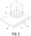
- FIG. 3
- is a perspective view illustrating a positional relationship between the belt-like member and an image pick-up device according to the embodiment of the present invention.
- FIG. 4
- is a side view illustrating the positional relationship between the belt-like member and the image pick-up device according to the embodiment of the present invention.
- FIG. 5
- is a block diagram of the belt-like member cutting apparatus according to the embodiment of the present invention.
- FIG. 6
- is a flow chart depicting operations of a control device according to the embodiment of the present invention.
- FIG. 7
- is a schematic view illustrating positional relationships between the image pick-up position, a cutter, and the belt-like member according to the embodiment of the present invention.
- FIG. 8
- is an explanatory view of operations of the belt-like member cutting apparatus according to the embodiment of the present invention.
- FIG. 9
- is an explanatory view of operations of the belt-like member cutting apparatus according to the embodiment of the present invention.
- FIG. 10
- is a diagram illustrating a method for determining a cutting position in a conventional example.
- FIG. 11
- is a diagram illustrating a method for determining a cutting position in a conventional example.
- FIG. 12
- is a flow chart depicting a method for determining a cutting position according to the embodiment of the present invention.
- FIG. 13
- is a flow chart depicting the method for determining the cutting position according to the embodiment of the present invention.
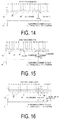
- FIG. 14
- is a diagram illustrating the method for determining the cutting position according to the embodiment of the present invention.
- FIG. 15
- is a diagram illustrating the method for determining the cutting position according to the embodiment of the present invention.
- FIG. 16
- is a diagram illustrating the method for determining the cutting position according to the embodiment of the present invention.
- FIG. 17
- is an explanatory diagram of operations of the belt-like member cutting apparatus.
- FIG. 18
- is an explanatory diagram of operations of the belt-like member cutting apparatus.
- FIG. 19
- is a schematic view illustrating positional relationships between the image pick-up position, the cutter and the belt-like member according to a modified example of the embodiment of the present invention.
-
FIGS. 1 to 19 illustrate a present embodiment, whereFIG. 1 is a plan view of main parts of a belt-like member cutting apparatus,FIG. 2 is a side view of main parts of the belt-like member cutting apparatus,FIG. 3 is a perspective view illustrating a positional relationship between the belt-like member and an image pick-up device,FIG. 4 is a side view illustrating the positional relationship between the belt-like member and the image pick-up device,FIG. 5 is a block diagram of the belt-like member cutting apparatus,FIG. 6 is a flow chart depicting operations of a control device,FIG. 7 is a schematic view illustrating positional relationships between the image pick-up position, a cutter, and the belt-like member, andFIGS. 8 to 19 are explanatory diagrams of operations of the belt-like member cutting apparatus. - This belt-like member cutting apparatus has a
cutter 10, an image pick-updevice 20, a plurality of cutting blades CT, and a plurality of winding rollers RL.
Thecutter 10 is movably provided in a width direction of a belt-like member WB pulled out from a belt-like member wound body. Thecutter 10 is cutting means capable of forming cuts in a downstream side end in a length direction of the belt-like member WB.
The image pick-updevice 20 is movably provided in the width direction of the belt-like member WB pulled out from the belt-like member wound body. The plurality of cutting blades CT are arranged with intervals therebetween in the width direction of the belt-like member WB pulled out from the belt-like member wound body.
Each of the plurality of winding rollers RL winds up each of strip members SP formed by each of the cutting blades CT passing through the belt-like member WB. - The belt-like member WB is formed of an unvulcanized rubber material and is formed in a belt shape. For example, a thickness dimension thereof is several mm, a width dimension thereof is substantially 240 mm, and a length dimension thereof is several tens of m. Further, reinforcement cords RC are embedded in the belt-like member WB so as to be arranged side by side with each other. Specifically, for example, 240 of the reinforcement cords RC are embedded so as to be arranged substantially parallel to each other, which form a product generally called 70 ends. The 70 ends is formed of 70 of the reinforcement cords arranged over a distance of a width of 50 mm. Each of the reinforcement cords RC is formed of a metal cord or a rigid fiber cord such as polyester or nylon. Each of the reinforcement cords RC is embedded so as to extend in the length direction of the belt-like member WB. A cut end surface ES is formed on the downstream side end in the length direction of the belt-like member WB. This cut end surface ES is an inclined cross section obtained by diagonally cutting the downstream side end in the length direction of the belt-like member WB, such that the cut end surface ES is oriented to one side in the thickness direction of the belt-like member WB. Further, cross sections of each of the reinforcement cords WB appear in the cut end surface ES of the downstream side end in the length direction of the belt-like member WB. Further, as illustrated in
FIG. 4 , it is preferable that an angle α formed by the cut end surface ES and one surface in the thickness direction of the belt-like member be equal to or greater than 30 degrees and equal to or less than 60 degrees. In the present embodiment, the cut end surface ES is cut so as to be within this angle range. - The
cutter 10 has a pair ofblades 10a that can be opened and closed in the thickness direction of the belt-like member WB.
Thecutter 10 is supported by aframe 11 provided so as to extend in the width direction of the belt-like member WB. Thecutter 10 is configured to be moved in the width direction of the belt-like member WB by a widthdirection movement mechanism 12 provided on theframe 11. - Further, a length
direction movement mechanism 13, which moves thecutter 10 in the length direction of the belt-like member 10, is provided on theframe 11. In this way, in front of the downstream side end in the length direction of the belt-like member WB, thecutter 10 can movably operate in the width direction of the belt-like member WB. In addition, due to the lengthdirection movement mechanism 13, thecutter 10 can move toward an upstream side end in the length direction of the belt-like member WB. In this way, the downstream side end in the length direction of the belt-like member WB is caused to be positioned between each of theblades 10a, and, by closing each of theblades 10a, a cut can be made in the downstream side end in the length direction of the belt-like member WB. - The image pick-up
device 20 is formed by a known CCD camera, for example. The image pick-updevice 20 is arranged so as to capture an image of the cross section on the downstream side end in the length direction of the belt-like member WB. Here, the cross section whose image is captured as described above is the cut end surface ES, and the cut end surface ES is the inclined surface oriented to the one side in the thickness direction of the belt-like member WB. As a result, the image pick-updevice 20 can capture an image of the cut end surface ES as the cross section on the downstream side end in the length direction of the belt-like member WB from the one side in the thickness direction of the belt-like member WB. Note that, in the present embodiment, the inclined cut end surface ES is used as the cross section of the downstream side end in the length direction of the belt-like member WB, but the image pick-updevice 20 may capture an image of a cross section obtained by cutting the downstream side end in the length direction of the belt-like member WB in the thickness direction. - Further, a
lighting device 20a having a ring shaped frame is attached to the image pick-updevice 20, for example, and a plurality of light emitting diodes LED are attached to the bottom surface of the ring shaped frame. Specifically, thelighting device 20a is configured to illuminate the cut end surface ES on the downstream side end in the length direction of the belt-like member WB, from the vicinity of the image pick-updevice 20. - The image pick-up
device 20 is supported by aframe 21 provided so as to extend in the width direction of the belt-like member WB, and the image pick-updevice 20 is moved in the width direction of the belt-like member WB by amovement mechanism 22 provided on theframe 21. Note that the widthdirection movement mechanism 12, the lengthdirection movement mechanism 13, and themovement mechanism 22 are configured using a servo motor, and a ball screw, for example. - The
cutter 10, the widthdirection movement mechanism 12, the lengthdirection movement mechanism 13, the image pick-updevice 20, and themovement mechanism 22 are connected to acontrol device 30 configured by a known computer (seeFIG. 5 ).
In addition, on a captured image G that is successively captured by the image pick-updevice 20, thecontrol device 30 is configured to detect, for each of the captured images G, positions of each of the reinforcement cords RC appearing in the cut end surface ES on the downstream side end in the length direction of the belt-like member WB, and a position of theblades 10a of thecutter 10. Thecontrol device 30 is further configured to control thecutter 10, the widthdirection movement mechanism 12, the lengthdirection movement mechanism 13, the image pick-updevice 20, and themovement mechanism 22 on the basis of the positions of each of the reinforcement cords RC and of theblades 10a. - The
control device 30 has acontrol unit 30a and aprocessing unit 30b. Thecontrol unit 30a is configured to control operations of thecutter 10, the widthdirection movement mechanism 12, the lengthdirection movement mechanism 13, and themovement mechanism 22. - The
processing unit 30b is configured to perform processing on the captured image transmitted from the image pick-updevice 20, and determine the cutting position on the belt-like member WB. Specifically, theprocessing unit 30 has aposition detecting unit 30c, aninterval calculating unit 30d, an actualnumber setting unit 30e, and a cuttingposition determining unit 30f.
Thecontrol device 30 is configured, for example, by a computer having a CPU and a memory. In this case, thecontrol unit 30a and theprocessing unit 30b are formed as a software module, by activating a program stored in a memory (not illustrated). Specifically, thecontrol unit 30a, theposition detecting unit 30c, theinterval calculating unit 30d, the actualnumber setting unit 30e, and the cuttingposition determining unit 30f are a software module.
Theposition detecting unit 30c performs known image processing on the captured image G of the image pick-updevice 20, such as averaging processing, binarization processing, and expansion processing, and thus performs display such that, on the captured image G, only images of each of the reinforcement cords RC and theblades 10a are displayed in white, for example. As illustrated inFIG. 7 , for example, thecontrol device 30 is configured to continuously detect, on the captured image G, a position (a coordinate) P1 of each of the reinforcement cords RC in the width direction of the belt-like member of the downstream side end (a right end of each of the reinforcement cords RC inFIG. 1 ) in the width direction of the belt-like member, and a position (a coordinate) P2 of tip ends of theblades 10a in the width direction of the belt-like member. Operations of theposition detecting unit 30c, theinterval calculating unit 30d, the actualnumber setting unit 30e, and the cuttingposition determining unit 30f will be described in the following description of a method to determine the cutting position.
In the description below, the width direction of the belt-like member WB matches a latitudinal direction of the captured image G. Calibration is performed in advance such that the coordinates of the positions detected from the captured image according to the present embodiment correspond to numerical values of coordinates of corresponding actual positions. - Note that when the light from the
lighting device 20a is reflected at the cross section of the belt-like member WB, if specularly reflected light is oriented toward the image pick-updevice 20, images of both the portions of rubber inside the cross section and the portions of each of the reinforcement cords RC are illuminated in white, and it is difficult to distinguish each of the reinforcement cords RC on the captured image G. However, in the present embodiment, the cut end surface ES diagonally inclined on the downstream side end in the length direction of the belt-like member WB is used as the cross section, and therefore, the specularly reflected light is inhibited from being oriented toward the image pick-updevice 20. As a result, each of the reinforcement cords RC can be reliably distinguished on the captured image G. - Below, control by the
control device 30 and operations of the belt-like member cutting apparatus will be described with reference to a flow chart depicted inFIG. 6 andFIGS. 7 to 14 . In the present embodiment, an explanation is made in which the belt-like member WB is cut and a plurality of the strip members SP each having fourteen of the reinforcement cords RC are created. Further, in an initial state, this belt-like member cutting apparatus is configured such that thecutter 10 is arranged at the first end (an end on the left side on paper inFIG. 7 ) of the width direction of the belt-like member WB, and such that the image pick-updevice 20 captures an image of the portion including the first end in the width direction of the belt-like member WB. The image of theblades 10a of thecutter 10 is positioned within an angle of view of the image pick-updevice 20. Further, the belt-like member cutting apparatus is configured such that the images of at least nineteen of the reinforcement cords RC appearing at the cut end surface ES of the belt-like member WB are arranged inside the angle of view of the image pick-updevice 20. - First, when, in accordance with an instruction of the
control unit 30a, the cut end surface ES of the belt-like member WB pulled out from the belt-like member wound body and theblades 10a of thecutter 10 are arranged inside the angle of view of the image pick-up device 20 (SA1), as depicted inFIG. 6 , theposition detecting unit 30c continuously detects, on the captured image G, the positions P1 of the images of the reinforcement cords RC along the width direction of the belt-like member WB, from the first end side.
As illustrated inFIG. 8 , on the basis of the position P1 of the image of the reinforcement cord RC first detected on the captured image G from the first end side along the width direction of the belt-like member WB, the cuttingposition detecting unit 30f sets a first cutting position Xa (SA2). Specifically, as illustrated inFIG. 8 , a position that is, for example, 0.2 mm to the first end side (the left side on paper inFIG. 8 ) from the position P1 of the image of the first reinforcement cord RC from the first end side in the width direction of the belt-like member WB, is set as the cutting position Xa. - Next, as illustrated in
FIG. 9 , in accordance with an instruction of thecontrol unit 30a, thecutter 10 is moved by the widthdirection movement mechanism 12 in the width direction of the belt-like member WB toward the second end side on the opposite side to the first end, until the position P2 of the tip ends of theblades 10a of thecutter 10 is arranged at the first cutting position Xa (SA3). In addition, after closing theblades 10a, thecontrol unit 30a controls thecutter 10 such that theblades 10a open. In this way, a cut is made in the downstream side end in the length direction of the belt-like member WB (SA4). - Next, in accordance with an instruction of the
control unit 30a, the image pick-updevice 20 is moved toward the second end side in the width direction of the belt-like member such that the cut formed by the processing at SA4 is positioned on an edge of the captured image G (SA5). - Next, the
position detecting unit 30c detects the position P1 of the image of each of the reinforcement cords RC from the captured image G transmitted from the image pick-updevice 20. Further, on the basis of the position P1 of the detected image of each of the reinforcement cords RC, theposition detecting unit 30c determines, from the cutting position Xa on the first end side of the captured image G, detection numbers of the images of the reinforcement cords RC in order toward the second end side (SA6). In addition, on the basis of the position of the detected image of each of the reinforcement cords RC and on the detection numbers, the actualnumber setting unit 30e determines an actual number of each of the reinforcement cords RC (SA7). On the basis of the actual numbers and the positions of the reinforcement cords RC, the cuttingposition setting unit 30f sets the next cutting position Xa by the cutter 10 (SA8). As will be described below, the actual number is a number obtained by correcting the detection number. - While processing from SA6 to SA8 will be described later, it should be noted that if an image of the weft thread appears in the captured image G, in actuality it is sometimes detected as the image of a single reinforcement cord formed by a plurality of the adjacent reinforcement cords RC being joined together. In this case, the detection number is assigned to the image of the single reinforcement cord instead of to the plurality of reinforcement cords RC. Therefore, in the present embodiment, even when the detection numbers of the plurality of reinforcement cords RC are assigned as the image of the single reinforcement cord, a number representing the actual order of the reinforcement cords RC is obtained by correcting the detection number, and this number is determined as the actual number. This actual number is used to set the cutting position Xa.
- Next, the
control unit 30a controls the widthdirection movement mechanism 12 to cause thecutter 10 to move toward the second end side in the width direction of the belt-like member WB, until the position P2 of the tip ends of theblades 10a is arranged in the cutting position Xa (SA9). - Next, the
control unit 30a controls the lengthdirection movement mechanism 13 to cause thecutter 10 to move toward the upstream side end in the length direction, and at the same time, controls thecutter 10 to close each of theblades 10a. Further, thecontrol unit 30a controls thecutter 10 to cause each of theblades 10a to open, and at the same time, controls the lengthdirection movement mechanism 13 to cause thecutter 10 to move toward the downstream side end in the length direction (SA10). In this way, a cut C is made at the cutting position Xa on the downstream side end in the length direction of the belt-like member WB. - Specifically, at step SA9, by causing the
blades 10a to be arranged at the cutting position Xa, thecutter 10 is arranged in a position at which the cutting can be performed, between the fourteenth reinforcement cord RC and the fifteenth reinforcement cord RC from the position at which the immediately preceding cut was made. - Following this, step SA5 to step SA10 are repeated a predetermined number of times (22 times in the present embodiment) (SA11). In this way, twenty three of the cuts C are made in the downstream side end in the length direction of the belt-like member WB.
- Next, the above-described processing at SA6 to SA8 will be described in detail.
- When the image of the weft thread joining the reinforcement cords RC does not appear in the cross section on the downstream side end in the length direction of the belt-like member WB, as illustrated in
FIG. 10 , there is no displacement between the detection numbers of the images of the reinforcement cords RC automatically detected by theposition detecting unit 30c and the actual numbers of the reinforcement cords RC counted from the first end side in the width direction of the band-like member WB. Specifically, theposition detecting unit 30c appropriately detects coordinates X1 to X14 of the image of each of the reinforcement cords RC without problem. However, when the weft thread joining the reinforcement cords RC appears in the cross section on the downstream side end in the length direction of the belt-like member WB, as illustrated inFIG. 11 , the adjacent reinforcement cords RC are joined by an image of a weft thread WF. In this case, theposition detecting unit 30c detects the images of the plurality of the reinforcement cords RC as the image of the single reinforcement cord RC, and, as a result, assigns the detection number to the image of the single reinforcement cord RC. In the case ofFIG. 11 , the images of the sixth reinforcement cord and the seventh reinforcement cord are joined by the image of the weft thread WF, and the image of the eighth reinforcement cord is detected as the image of the seventh reinforcement cord. As a result, the image of the sixteenth reinforcement cord is detected as the image of the fifteenth. Taking this type of case into account, in the present embodiment, by performing processing depicted in flow charts inFIG. 12 andFIG. 13 , the actual number, which represents which number the reinforcement cord actually is, is calculated from the number (detection number) of the image of the detected reinforcement cord, and thereby determined. In this way, even when the images of the adjacent reinforcement cords RC are joined together and the images of the plurality of reinforcement cords RC are detected as the image of the single reinforcement cord RC, the actual number allows the cutting position Xa to be set between the fourteenth reinforcement cord RC and the fifteenth reinforcement cord. The processing to determine the actual number by the calculation is performed by theinterval calculating unit 30d and the actualnumber setting unit 30e. - Next, the processing depicted in the flow charts in
FIG. 12 andFIG. 13 will be described. - After determining the detection numbers of the images of each of the reinforcement cords RC detected by the
position detecting unit 30a (SB1), theinterval calculating unit 30d extracts coordinates of the positions, in relation to a reference position, of the images of the reinforcement cords RC having the adjacent detection numbers (SB2). The coordinates of the above-described positions are, for example, coordinates on an X axis extending in the width direction of the belt-like member WB, where the cutting position that has been established immediately before is taken as a position coordinate 0 (the reference position). The unit of the coordinates is mm (millimeters). - After that, the actual
number setting unit 30e sets, as an average cord interval Lm, an average value of an interval between the adjacent reinforcement cords RC, which has been input in advance by an operator (SB3). For example, the value used as the average value of the interval between the adjacent reinforcement cords RC is obtained by dividing the width of the belt-like member WB or a width of a design target by a total number of the embedded reinforcement cords RC. Thecontrol device 30 further sets a variable n (= a natural number), indicated below, to 1 (SB4). - Next, the
interval calculating unit 30d calculates an interval L (= Xn + 1 - Xn) between a coordinate Xn of the reinforcement cord RC having an n-th detection number from the reference position and a coordinate Xn + 1 of the reinforcement cord RC having the n + 1th detection number (SB5). The actualnumber setting unit 30e determines whether or not the calculated interval L satisfies (Lm × 0.5 ≤ L < Lm × 1.5) (SB6). In place of Lm × 0.5 ≤ L < Lm × 1.5, Lm × k ≤ L < Lm × (2 - k) may be used, where k is equal to or greater than 0.2 and equal to or less than 0.8. In this case, it is preferable that k = 0.5. When variations in the interval between the reinforcement cords RC, centering on the average cord interval Lm, are large, it is preferable that the value of k be made smaller, and when the variations are small, that the value of k be made larger. - When, as a result of the above-described determination at SB6, the interval L satisfies (Lm × 0.5 ≤ L < Lm × 1.5), the actual
number setting unit 30e moves to processing at SB12 (to be described later) with the actual number of the reinforcement cord RC having the n + 1th detection number set as the n + 1th actual number (SB7). When the interval L does not satisfy (L × 0.5 ≤ L < Lm × 1.5), the actualnumber setting unit 30e sets a variable p (a natural number) to 1 (SB8), and determines whether or not the interval L satisfies {Lm × (p + 0.5) ≤ L < Lm × (p + 1.5)} (SB9). - When, as a result of this determination, the interval L satisfies {Lm × (p + 0.5) ≤ L < Lm × (p + 1.5)}, the actual
number setting unit 30e sets the actual number of the reinforcement cord RC having the n + 1th detection number as the n + 1 + p-th actual number (SB10) and moves to the processing at SB12 (to be described later). When the interval L does not satisfy {Lm × (p + 0.5) ≤ L < Lm × (p + 1.5)}, the actualnumber setting unit 30e adds 1 to the value of the variable p and sets this as the new value of the variable p (SB11), then moves to the above-described determination processing at SB9. - When, as a result of the above-described determination at SB7, the interval L satisfies (Lm × 0.5 ≤ L < Lm × 1.5), and when, as a result of the determination at the above-described SB10, the interval L satisfies {Lm × (p + 0.5) ≤ L < Lm × (p + 1.5)}, 1 is added to the variable n and set as the new value of the variable n (SB12), the actual
number setting unit 30e determines whether or not the value of the variable n is equal to 15 (SB13). As a result of this determination, when the variable n is not equal to 15, the actualnumber setting unit 30e moves to the above-described processing at SB5, and when the variable n is equal to 15, the actualnumber setting unit 30e determines whether or not the reinforcement cord RC to which the detection number is assigned and for which the actual number is 15 actually exists (SB14).
In this way, in the present embodiment, depending on a ratio of the interval L between the adjacent reinforcement cords to the average cord interval Lm, of the detection numbers for the reinforcement cords having the adjacent detection numbers, the larger of the detection numbers is corrected so as to be a larger number and is set as the actual number. - As a result of this determination, when the detection numbers are assigned to the images and the reinforcement cord RC having the
actual number 15 exists, the cuttingposition determining unit 30f sets the cutting position Xa on the basis of the position of the reinforcement cord having the actual number 15 (SB15). For example, as illustrated inFIG. 14 , when there are none of the reinforcement cords RC that have been joined by the weft thread WF, a value Lm × j is calculated by multiplying the average cord interval Lm by a coefficient j (where j is a number greater than 0 and less than 1), and the cutting position Xa is set as a position of an X coordinate value obtained by subtracting the value Lm × j from the position of a coordinate X15 of the reinforcement cord RC having theactual number 15. In this way, the cutting position Xa can be set between the reinforcement cord RC having the fourteenth actual number and the reinforcement cord RC having the fifteenth actual number, and the strip member having fourteen of the reinforcement cords RC can thus be manufactured. Note that in the present embodiment, the position of each of the reinforcement cords RC is established by the position of the end on the first end side, and a value of the coefficient j is therefore 0.2. It is preferable that the coefficient j be set as appropriate in accordance with the detection position of each of the reinforcement cords RC. - Further, for example, as illustrated in
FIG. 15 , when the sixth reinforcement cord RC and the seventh reinforcement cord RC are joined by the weft thread WF and the two reinforcement cords RC are thus detected as the image of the single reinforcement cord RC, the eighth reinforcement cord RC in actuality becomes the seventh detection number and the detection number is displaced by 1. However, as a result of the above-described processing, the reinforcement cord RC having the fifteenth actual number can be determined, and thus the cuttingposition determining unit 30f calculates the value Lm × j obtained by multiplying the average cord interval Lm by the coefficient j (where j is a number greater than 0 and less than 1), and sets the cutting position Xa as a position of an X coordinate value obtained by subtracting the value Lm × j from the position of the coordinate X14 of the reinforcement cord RC having the fifteenth actual number. In this way, the cutting position Xa can be set between the reinforcement cord RC having the fourteenth actual number and the reinforcement cord having the fifteenth actual number, and the strip member having fourteen of the reinforcement cords RC can thus be manufactured. - As a result of the determination at the above-described SB14, when the detection numbers are assigned and the reinforcement cord having the
actual number 15 does not exist, the cuttingposition determining unit 30f sets the cutting position Xa on the basis of the actual number that is smaller than 15 and that is the largest of the actual numbers, namely, on the basis of the position of the reinforcement cord having the actual number that is closest to 15 (SB16). The largest number of the above-described actual numbers is assumed to be N. For example, as illustrated inFIG. 16 , when the fourteenth to the sixteenth reinforcement cords RC are joined by the weft thread WF and the three reinforcement cords RC are thus detected as the image of the single reinforcement cord RC, the detection number of the seventeenth reinforcement cord RC becomes the fifteenth detection number and there is displacement of the detection numbers. However, as a result of the above processing, the reinforcement cord RC having the fifteenth detection number is established to be the reinforcement cord RC having the seventeenth actual number. Thus, the cuttingposition determining unit 30f sets the cutting position Xa while taking as reference the coordinate X14 of the image of the reinforcement cord RC having the fourteenth actual number, which is detected one before the fifteenth reinforcement cord RC. In this case, specifically, an actual number N of the reinforcement cord RC having the fourteenth detection number is the fourteenth actual number, and thus the cutting position Xa is set to a position specified by X14 + {Lm × (15 - N) - Lm × j} (where j is a number greater than 0 and less than 1). In an example illustrated inFIG. 16 , the actual number N = 14 is the largest of the existing numbers, but there are cases in which there is no actual number N = 14, and the actual number is N = 12 or 13. Therefore, in the present embodiment, the cutting position Xa is set to be in a position separated by Lm × (t + 1 - N) - Lm × j (where j is a number greater than 0 and less than 1) from the position of the reinforcement cord having the actual number N. In this case, the fact that the actual number N is the largest number equal to or less than 15 is preferable from the point of view of accurately setting the cutting position Xa. - Next, as illustrated in
FIG. 17 , a plurality of (eighteen in the present embodiment) cutting blades CT, which are provided at intervals in the width direction of the belt-like member WB, are inserted into each of the cuts C. Next, as illustrated inFIG. 18 , the downstream side ends of each of the plurality of strip members SP formed by each of the cutting blades CT passing through the belt-like member WB are each mounted on the winding rollers RL. At the same time, each of the strip members SP is wound on by each of the winding rollers RL and the belt-like member WB is thus cut along the reinforcement cords RC, and the plurality of strip members SP are formed. An operation to insert each of the cutting blades CT into each of the cuts C can be performed automatically using a known conveyor or the like, and can also be performed manually by an operator. - In this way, according to the method for cutting the belt-like member and the apparatus therefor of the present embodiment, the image pick-up
device 20 can capture an image of the cross section at the one end in the length direction of the belt-like member WB having embedded therein the plurality of reinforcement cords RC arranged in parallel to each other and the weft thread WF provided so as to intersect the reinforcement cords RC. Theposition detecting unit 30b of thecontrol device 30 detects the positions, in the width direction of the belt-like member WB, of the images of each of the reinforcement cords RC appearing in the cross section on the captured image obtained by the image capture. At the same time, theposition detecting unit 30b sets the detection numbers representing the order of arrangement of the reinforcement cords WB from the side of the first end in the width direction of the belt-like member WB. After that, theinterval calculating unit 30d of thecontrol device 30 calculates the interval L between the reinforcement cords RC having the adjacent detection numbers. Depending on the ratio of the interval L to the average cord interval Lm between the adjacent reinforcement cords, of the detection numbers for the reinforcement cords having the adjacent detection numbers, the actualnumber setting unit 30e corrects the larger of the detection numbers so as to be a larger number and sets this as the actual number. Then, the cuttingposition determining unit 30f uses the actual number to determine the cutting position in the width direction of the belt-like member WB. As a result, the strip member SP formed by cutting the belt-like member WB can be reliably provided with the desired number of reinforcement cords RC. - Specifically, the
position detecting unit 30c of thecontrol device 30 detects the positions P1 of the images of each of the reinforcement cords RC appearing on the downstream side end in the length direction of the belt-like member WB on the captured image G, and the position P2 of the image of the tip ends of theblades 10a of thecutter 10. Further, the actualnumber setting unit 30e uses the captured image G and determines the actual numbers on the basis of the detection numbers and the positions of the images of the detected reinforcement cords. Thecontrol unit 30a moves thecutter 10 until thecutter 10 is arranged in the position at which the cutting can be performed between the reinforcement cord having a predetermined actual number (the fourteenth in the present embodiment), and the next (the fifteenth in the present embodiment) reinforcement cord RC. After that, thecontrol unit 30 controls thecutter 10 to cause thecutter 10 to make the cuts C in the one end in the length direction of the belt-like member WB. After that, the plurality of cutting blades CT provided at mutual intervals in the width direction of the belt-like member WB are inserted into each of the cuts C made in the downstream side end in the length direction of the belt-like member WB, and the belt-like member WB is severed along the reinforcement cords RC by each of the cutting blades CT. In this way, the plurality of strip members SP each having the desired number of reinforcement cords RC are formed. Specifically, each of the strip members SP can be reliably provided with the desired number of reinforcement cords RC. Use of the strip members SP in a tire is extremely advantageous in achieving an improvement in tire quality. - In the present embodiment, when the interval L and the average interval Lm satisfy Lm × (p + k) ≤ L < Lm × (p + 2 - k) (where p is an integer equal to or greater than 0, and k is a number equal to or greater 0.2 and equal to or less than 0.8), it is preferable that the actual
number setting unit 30e set, for the larger of the detection numbers of the adjacent reinforcement cords RC, a sum of the larger detection number and the integer p as the actual number. - Further, it is preferable that the cutting position Xa determined by the cutting
position determining unit 30f be a position between the adjacent reinforcement cords among the reinforcement cords RC. - When manufacturing the strip member SP having embedded therein a number t (t is a natural number) of the reinforcement cords RC, when the reinforcement cord RC having the t-th actual number is not detected and the N-th reinforcement cord RC whose actual number is smaller than the t-th actual number is detected, it is preferable that the cutting
position determining unit 30f use the position of the N-th reinforcement cord RC and the average cord interval Lm to determine the cutting position Xa. - At this time, it is preferable that the N-th reinforcement cord RC be the reinforcement cord having the largest number among the plurality of actual numbers that are smaller than the t-th actual number.
- It is preferable that the cutting
position determining unit 30f determine the position of the cutting position Xa so as to be separated from the position of the N-th reinforcement cord RC to the side opposite to the first end in the width direction, by Lm × (t + 1 - N) - Lm × j (where j is a number greater than 0 and less than 1). - It is preferable that the positions, in the width direction of the belt-like member WB, of the images of the reinforcement cords RC be the positions of end portions of the images of the reinforcement cords RC in the width direction.
- As in the present embodiment, after the cutting position Xa has been determined and the cut C has been made in the cutting positions Xa, it is preferable to repeat the following:
- (1) to perform, with respect to portions of the belt-like member WB to be cut on the basis of the determination of the cutting position Xa, image capture of the cross section of the one end in the length direction of the belt-like member WB at a portion adjoining the opposite side to the first side,
- (2) to detect the positions, in the width direction of the belt-like member WB, of the images of each of the reinforcement cords RC appearing in the cross section on the captured image G obtained by the image capture,
- (3) to use the captured image G of the adjoining portion to set the detection numbers representing the order of arrangement, from the first end side in the width direction of the belt-like member WB, of the reinforcement cords of the above-described adjoining portion,
- (4) to calculate the interval L between the reinforcement cords for the reinforcement cords RC having the adjacent detection numbers, and, depending on the ratio of the interval L to the average cord interval Lm between the adjacent reinforcement cords, of the detection numbers of the reinforcement cords having the adjacent detection numbers, to correct the larger detection number so as to be a larger number and set this as the actual number, and
- (5) to determine, using the actual number, the cutting position in the width direction of the belt-like member WB, such that the number of the reinforcement cords included in the strip members SP formed by the belt-like member WB is a set number.
- In the captured image G, in addition to the images of the reinforcement cords RC, the image of the weft thread may also be captured.
- As in the present embodiment, after one of the cuts C has been formed in the cutting position Xa at the downstream side end in the length direction of the belt-like member WB, it is preferable that the image pick-up
device 20 be moved toward the second end in the width direction of the belt-like member WB such that the tip ends of theblades 10a of the cuttingapparatus 20 are arranged in an end portion inside the angle of view of the image pick-updevice 20. In this way, as in the present embodiment, for example, even when performing cutting of the belt-like member WB having the 240 reinforcement cords RC, there is no need for the image pick-updevice 20 to capture the image of the 240 reinforcement cords RC at once, there is also no need to unnecessarily improve the resolution of the image pick-updevice 20, and there is also no need to arrange a plurality of the image pick-updevices 20 in the width direction of the belt-like member WB. This point is extremely advantageous from the point of view of achieving device simplification and reducing manufacturing costs. - As in the present embodiment, it is preferable that the belt-like member WB be used that is diagonally inclined on the downstream side end in the length direction such that the cut end surface ES is oriented toward the one side in the thickness direction of the belt-like member WB, and that the image pick-up
device 20 capture the image of the downstream side end in the length direction of the belt-like member WB, from the one side in the thickness direction of the belt-like member WB. In this way, in comparison to a case in which the cut end surface ES has a surface that is substantially vertical on the downstream side end in the length direction such that the surface faces in the length direction of the belt-like member WB, and the image pick-updevice 20 performs the image capture of the cut end surface ES from the length direction of the belt-like member WB, the cuttingapparatus 10 and the image pick-updevice 20 can be easily arranged such that there is no mutual interference in the arrangement thereof, and this is extremely advantageous in achieving device simplification. - By diagonally cutting the downstream side end in the length direction of the belt-like member WB, even when the
lighting device 20a, for example, is configured to illuminate the cut end surface ES on the downstream side end in the length direction of the belt-like member WB from a position in the vicinity of the image pick-updevice 20, specularly reflected light is inhibited from being oriented toward the image pick-updevice 20, and each of the reinforcement cords RC can be reliably distinguished on the captured image G. This is extremely advantageous in terms of accurately performing the cutting of the belt-like member WB. In the present embodiment, thelighting device 20a is commonly used with the image pick-updevice 20, and thus, making the cut end surface ES on the downstream side end in the length direction of the belt-like member WB the inclined surface is extremely advantageous in terms of accurately performing the cutting of the belt-like member WB. - In addition, it is preferable to make the angle α formed by the cut end surface ES and the one surface in the thickness direction of the belt-like member be equal to or greater than 30 degrees and equal to or less than 60 degrees, in terms of easily and reliably distinguishing each of the reinforcement cords RC on the captured image G. Specifically, when the angle α is less than 30 degrees, the specularly reflected light is easily oriented toward the image pick-up
device 20, and when the angle α exceeds 60 degrees, cases occur in which, depending on the position of the image pick-updevice 20, the image of each of the reinforcement cords RC cannot be reliably captured. It is therefore preferable for the angle α to be equal to or greater than 30 degrees and equal to or less than 60 degrees. - In the present embodiment, the image pick-up
device 20 performs the image capture such that the image of the one end in the length direction of the belt-like member WB is captured from the one side in the thickness direction of the belt-like member WB. With respect to this, as illustrated inFIG. 19 , it is also preferable that the image pick-updevice 20 perform the image capture of the downstream side end in the length direction of the belt-like member WB from an inclined direction that is inclined with respect to the length direction and the thickness direction of the belt-like member WB. Here, inFIG. 19 , the downstream side end in the length direction of the belt-like member WB is cut substantially vertically with respect to the one surface in the thickness direction of the belt-like member WB, and the angle α formed between the cut end surface ES and the one surface in the thickness direction of the belt-like member WB is substantially 90 degrees. In this case, by performing the image capture of the cut end surface ES on the downstream side end in the length direction of the belt-like member WB from the diagonal direction, even when thelighting device 20a, for example, illuminates the cut end surface ES on the downstream side end in the length direction of the belt-like member WB from a position in the vicinity of the image pick-updevice 20, the specularly reflected light is inhibited from being oriented toward the image pick-updevice 20, and each of the reinforcement cords RC can be reliably distinguished on the captured image G. Therefore, a mode of the lighting and the cut end surface ES as illustrated inFIG. 19 is extremely advantageous in terms of accurately performing the cutting of the belt-like member WB. - Even when the end surface on the downstream side end in the length direction of the belt-like member WB is diagonally inclined, as long as the specularly reflected light is not oriented toward the image pick-up
device 20, as illustrated inFIG. 19 , it is preferable that the image pick-updevice 20 perform the image capture from the inclined direction that is inclined with respect to the length direction and the thickness direction of the belt-like member WB. Even in this case, the same operational effects can be achieved as in the example illustrated inFIG. 19 . Further, the image capture of the downstream side end in the length direction of the belt-like member WB by the image pick-updevice 20 can be performed from the length direction of the belt-like member WB. In this case also, the same operational effects as those described above can be achieved. - In the present embodiment, the example is given in which, on the captured image G, the first end side (the end on the left side on paper in
FIG. 7 ) of each of the reinforcement cords RC is detected as the position P1 of each of the reinforcement cords RC. However, another position of each of the reinforcement cords RC can be detected as the position of each of the reinforcement cords RC. - In the present embodiment, the example is given in which the 70 ends belt-like member WB is cut, but the present invention is not limited to the 70 ends example. For example, the technology of the present embodiment can be applied to a case such as when a 50 ends belt-like member, in which 50 reinforcement cords are arranged over a 50 mm width, is used and strip members having 10 reinforcement cords are formed.
- An average cord interval of the whole of the belt-like member WB may be used as the average cord interval Lm. However, there is a tendency for a density of the reinforcement cords RC to be greater at both end portions in the width direction than at a central portion in the width direction of the belt-like member WB. It is thus preferable for the actual
number setting unit 30e to actually measure and acquire, in advance, a distribution of the average cord interval Lm for each of locations of the belt-like member WB and for the acquired distribution to be used to set the average cord interval Lm corresponding to each of the locations of the belt-like member from which the strip member is to be made. - Further, in the present embodiment, the example is given in which, on the captured image G, the tip ends of the
blades 10a of thecutter 10 are detected as the position P2 of thecutter 10. However, another position of thecutter 10 can be detected as the position of thecutter 10. - The present technology relates to a method for cutting a belt-like member, having embedded therein a plurality of reinforcement cords, along the reinforcement cords, and an apparatus therefor, in order to manufacture strip members that are wound onto an outer peripheral surface of a belt member in manufacturing steps of an automobile tire, for example. In the present technology, a position of each of reinforcement cords is detected from a captured image, and, on the basis of an interval between the detected adjacent reinforcement cords and an average cord interval, a cutting position is set, determining which of each of the reinforcement cords is actually the reinforcement cord of a specific number. As a result, the number of the reinforcement cords of the strip member formed by cutting the belt-like member can be reliably ensured to be a desired number.
-
- 10
- Cutter
- 10a
- Blade
- 11
- Frame
- 12
- Width direction movement mechanism
- 13
- Length direction movement mechanism
- 20
- Image pick-up device
- 20a
- Lighting device
- 21
- Frame
- 22
- Movement mechanism
- 30
- Control device
- WB
- Belt-like member
- RW
- Belt-like member wound body
- SP
- Strip
- CT
- Cutter blade
- RL
- Winding roller
- RC
- Reinforcement cord
- ES
- Cut end surface
- G
- Captured image
- P1
- Position of reinforcement cord
- P2
- Position of tip ends of blades
- C
- Cut
Claims (19)
- A method for cutting a belt-like member for manufacturing a plurality of strip members by cutting the belt-like member in a length direction of the belt-like member, the method for cutting the belt-like member comprising the steps of:performing image capture of a cross section of one end in a length direction of a belt-like member having embedded therein a plurality of reinforcement cords arranged in parallel to each other and a weft thread provided so as to intersect the reinforcement cords;detecting a position, in a width direction of the belt-like member, of an image of each of the reinforcement cords appearing in the cross section within a captured image obtained by the image capture, along with setting detection numbers representing an arrangement order of the reinforcement cords from a first end side in the width direction of the belt-like member;calculating an interval L between the reinforcement cords for which the detection numbers of the reinforcement cords are adjacent to each other;setting an actual number that is obtained by correcting, depending on a ratio of the interval L to an average cord interval Lm between the adjacent reinforcement cords, a larger detection number of the detection numbers of the reinforcement cords for which the detection numbers are adjacent to each other so as to make the larger detection number larger; anddetermining a cutting position in the width direction of the belt-like member using the actual number, such that the number of the reinforcement cords included in a strip member made by the belt-like member is a set number.
- The method for cutting the belt-like member according to claim 1, wherein when the interval L and the average cord interval Lm satisfy Lm × (p + k) ≤ L < Lm × (p + 2 - k) (where p is an integer equal to or greater than 0, and k is a number equal to or greater than 0.2 and equal to or less than 0.8), with respect to a larger detection number of the detection numbers of the adjacent reinforcement cords, a sum of the larger detection number and the integer p is set as the actual number.
- The method for cutting the belt-like member according to claim 1 or claim 2, wherein
the cutting position is a position between the adjacent reinforcement cords among the reinforcement cords. - The method for cutting the belt-like member according to any one of claims 1 to 3, wherein
upon manufacturing the strip member having embedded therein a number t (t is a natural number) of the reinforcement cords, when the reinforcement cord having the t-th actual number is not detected and the reinforcement cord having an N-th actual number that is smaller than the t-th actual number is detected, the cutting position is established using a position of the N-th reinforcement cord and the average cord interval Lm. - The method for cutting the belt-like member according to claim 4, wherein
the N-th reinforcement cord is the reinforcement cord having the largest number, among the plurality of actual numbers smaller than the t-th actual number. - The method for cutting the belt-like member according to claim 4 or claim 5, wherein
the cutting position is established as a position separated from the position of the N-th reinforcement cord to a side opposite to the first end in the width direction, by Lm × (t + 1 - N) - Lm × j (where j is a number greater than 0 and less than 1). - The method for cutting the belt-like member according to any one of claims 1 to 6, wherein
a position of the image of the reinforcement cord in the width direction of the belt-like member is a position of an end portion of the image of the reinforcement cord in the width direction. - The method for cutting the belt-like member according to any one of claims 1 to 7, wherein
a distribution of the average cord interval for each of locations of the belt-like member is acquired in advance, and
using the distribution, the average cord interval Lm is set corresponding to each of the locations of the belt-like member from which the strip member is to be made. - The method for cutting the belt-like member according to any one of claims 1 to 8, wherein
after the cutting position has been determined and a cut has been made in the cutting position, the following steps are repeated:performing, with respect to a portion of the belt-like member to be cut on the basis of the determination of the cutting position, image capture of a cross section of the one end in the length direction of the belt-like member at a portion adjoining an opposite side to the first side;detecting the position, in the width direction of the belt-like member, of the image of each of the reinforcement cords appearing in the cross section on the captured image obtained by the image capture;setting the detection numbers representing an order of arrangement, from the first end side in the width direction of the belt-like member, of the reinforcement cords of the adjoining portion using the captured image of the adjoining portion;calculating an interval L between the reinforcement cords for which the detection numbers of the reinforcement cords are adjacent;setting an actual number that is obtained by correcting, depending on a ratio of the interval L to the average cord interval Lm between the adjacent reinforcement cords, the larger detection number of the detection numbers of the reinforcement cords for which the detection numbers are adjacent to each other so as to make the larger detection number larger; anddetermining a cutting position in the width direction of the belt-like member using the actual number, such that the number of the reinforcement cords included in the strip member made by the belt-like member is a set number. - The method for cutting the belt-like member according to any one of claims 1 to 9, wherein,
in the captured image, an image of the weft thread is also captured in addition to the image of the reinforcement cord. - A belt-like member cutting apparatus for manufacturing a plurality of strip members by cutting a belt-like member in a length direction of the belt-like member, the cutting apparatus comprising:a position detecting unit configured to detect, in a captured image of a cross section of one end in a length direction of a belt-like member having embedded therein a plurality of reinforcement cords arranged in parallel to each other and a weft thread provided so as to intersect the reinforcement cords, a position in a width direction of the belt-like member of an image of each of the reinforcement cords appearing in the cross section, and to set detection numbers representing an arrangement order of the reinforcement cords from a first end side in the width direction of the belt-like member;an interval calculating unit configured to calculate an interval L between the reinforcement cords for which the detection numbers of the reinforcement cords are adjacent to each other;an actual number setting unit configured to set an actual number that is obtained by correcting, depending on a ratio of the interval L to an average cord interval Lm between the adjacent reinforcement cords, a larger detection number of the detection numbers of the reinforcement cords for which the detection numbers are adjacent to each other such that the larger detection number is made larger;a cutting position determining unit configured to determine a cutting position in the width direction of the belt-like member using the actual number, such that the number of the reinforcement cords included in a strip member made by the belt-like member is a set number; anda cutter configured to manufacture the strip member by cutting the belt-like member at the determined cutting position.
- The belt-like member cutting apparatus according to claim 11, wherein when L and Lm satisfy Lm × (p + k) ≤ L < Lm × (p + 2 - k) (where p is an integer equal to or greater than 0, and k is a number equal to or greater than 0.2 and equal to or less than 0.8), with respect to the larger detection number of the detection numbers of the adjacent reinforcement cords, the actual number setting unit sets a sum of the larger detection number and the integer p as the actual number.
- The belt-like member cutting apparatus according to claim 11 or claim 12, wherein
the cutting position determined by the cutting position determining unit is a position between the adjacent reinforcement cords among the reinforcement cords. - The belt-like member cutting apparatus according to any one of claims 11 to 13, wherein
when manufacturing the strip member having embedded therein a number t (t is a natural number) of the reinforcement cords,
when the cutting position determining unit does not detect the reinforcement cord having the t-th actual number and detects the reinforcement cord having an N-th actual number that is smaller than the t-th actual number, the cutting position is established using a position of the N-th reinforcement cord and the average cord interval Lm. - The belt-like member cutting apparatus according to claim 14, wherein the N-th reinforcement cord is the reinforcement cord having the largest number, among the plurality of actual numbers smaller than the t-th actual number.
- The belt-like member cutting apparatus according to claim 14 or claim 15, wherein
the cutting position determining unit establishes the cutting position as a position separated from the position of the N-th reinforcement cord to a side opposite to the first end in the width direction, by Lm × (t + 1 - N) - Lm × j (where j is a number greater than 0 and less than 1). - The belt-like member cutting apparatus according to any one of claims 11 to 16, wherein
the position detecting unit establishes, as the position, in the width direction of the belt-like member, of the image of the reinforcement cord, a position of an end portion in the width direction of the image of the reinforcement cord. - The belt-like member cutting apparatus according to any one of claims 11 to 17, wherein
the actual number setting unit acquires in advance a distribution of the average cord interval for each of locations of the belt-like member, and uses the distribution to set the average cord interval Lm corresponding to each of the locations of the belt-like member from which the strip member is to be made. - The belt-like member cutting apparatus according to any one of claims 11 to 18 further comprising
an image pick-up device capturing, as the captured image, an image also of the weft thread in addition to the image of the reinforcement cord.
Applications Claiming Priority (2)
| Application Number | Priority Date | Filing Date | Title |
|---|---|---|---|
| JP2013230183 | 2013-11-06 | ||
| PCT/JP2014/079497 WO2015068777A1 (en) | 2013-11-06 | 2014-11-06 | Method for cutting belt-like member, and apparatus therefor |
Publications (3)
| Publication Number | Publication Date |
|---|---|
| EP3067190A1 true EP3067190A1 (en) | 2016-09-14 |
| EP3067190A4 EP3067190A4 (en) | 2017-09-20 |
| EP3067190B1 EP3067190B1 (en) | 2019-01-16 |
Family
ID=53041553
Family Applications (1)
| Application Number | Title | Priority Date | Filing Date |
|---|---|---|---|
| EP14860227.9A Not-in-force EP3067190B1 (en) | 2013-11-06 | 2014-11-06 | Method for cutting belt-like member, and apparatus therefor |
Country Status (6)
| Country | Link |
|---|---|
| US (1) | US11192319B2 (en) |
| EP (1) | EP3067190B1 (en) |
| JP (1) | JP6308219B2 (en) |
| KR (1) | KR101812948B1 (en) |
| CN (1) | CN105745066B (en) |
| WO (1) | WO2015068777A1 (en) |
Families Citing this family (3)
| Publication number | Priority date | Publication date | Assignee | Title |
|---|---|---|---|---|
| DE102016204050A1 (en) * | 2016-03-11 | 2017-09-14 | Continental Reifen Deutschland Gmbh | Method for producing a vehicle tire |
| WO2018017039A1 (en) * | 2016-07-18 | 2018-01-25 | Compagnie Generale Des Etablissements Michelin | Monitoring of the cure state of a tire through the use of microwaves |
| JP6999091B2 (en) * | 2018-02-07 | 2022-01-18 | 住友ゴム工業株式会社 | Manufacturing method of strip cord member |
Family Cites Families (10)
| Publication number | Priority date | Publication date | Assignee | Title |
|---|---|---|---|---|
| US3719114A (en) * | 1971-10-29 | 1973-03-06 | G Vischulis | Web trimmer control |
| US4173912A (en) * | 1978-08-18 | 1979-11-13 | The B. F. Goodrich Company | Fabric trimmer |
| JPH0722565B2 (en) | 1991-12-24 | 1995-03-15 | アズマ工業株式会社 | Vacuum cleaner suction nozzle |
| JPH06293206A (en) | 1993-04-06 | 1994-10-21 | Yokohama Rubber Co Ltd:The | Method and device for cutting sheet in which reinforcement cord is embedded |
| JP3441208B2 (en) * | 1994-12-22 | 2003-08-25 | 株式会社ブリヂストン | Ear rubber cutter position control device for rolling mill |
| JP4750966B2 (en) | 2001-04-26 | 2011-08-17 | 住友ゴム工業株式会社 | Manufacturing method and manufacturing apparatus for belt-like ply |
| JP4880207B2 (en) | 2004-06-16 | 2012-02-22 | 東洋ゴム工業株式会社 | Rubber cylinder |
| JP5168576B2 (en) | 2008-10-28 | 2013-03-21 | 横浜ゴム株式会社 | Method and apparatus for cutting strip member |
| DE102012007193B4 (en) * | 2012-04-12 | 2016-06-23 | Karl Eugen Fischer Gmbh | Cutting knife and Stahlcordschere comprising such a cutting blade |
| CN203236720U (en) * | 2013-05-13 | 2013-10-16 | 上海骄成机电设备有限公司 | Thermal cutting knife cutting device of tire cord |
-
2014
- 2014-11-06 CN CN201480059006.4A patent/CN105745066B/en active Active
- 2014-11-06 WO PCT/JP2014/079497 patent/WO2015068777A1/en not_active Ceased
- 2014-11-06 KR KR1020167013608A patent/KR101812948B1/en not_active Expired - Fee Related
- 2014-11-06 US US15/034,390 patent/US11192319B2/en not_active Expired - Fee Related
- 2014-11-06 JP JP2015528747A patent/JP6308219B2/en active Active
- 2014-11-06 EP EP14860227.9A patent/EP3067190B1/en not_active Not-in-force
Also Published As
| Publication number | Publication date |
|---|---|
| JPWO2015068777A1 (en) | 2017-03-09 |
| JP6308219B2 (en) | 2018-04-11 |
| CN105745066A (en) | 2016-07-06 |
| US11192319B2 (en) | 2021-12-07 |
| EP3067190B1 (en) | 2019-01-16 |
| US20160297159A1 (en) | 2016-10-13 |
| CN105745066B (en) | 2017-07-28 |
| EP3067190A4 (en) | 2017-09-20 |
| WO2015068777A1 (en) | 2015-05-14 |
| KR101812948B1 (en) | 2017-12-28 |
| KR20160078398A (en) | 2016-07-04 |
Similar Documents
| Publication | Publication Date | Title |
|---|---|---|
| Cemenska et al. | Automated in-process inspection system for AFP machines | |
| EP3067190B1 (en) | Method for cutting belt-like member, and apparatus therefor | |
| MX2016007745A (en) | Automated defrost and defog performance test system and method. | |
| US7400702B2 (en) | Tire inspection method | |
| JP2019215186A (en) | Seam checking device | |
| JP6475025B2 (en) | Shape error determination device, determination result image generation device, and shape error determination method | |
| EP3277445B1 (en) | Apparatus for improving the quality of tube bending and method that uses such apparatus | |
| US9574998B2 (en) | Line segment detection apparatus, and storage medium storing control program | |
| JP7207948B2 (en) | Appearance inspection method and program | |
| JP2006521544A (en) | Method for inspecting the quality criteria of a flat fabric structure embodied in a multi-layer format according to contours | |
| US20100105306A1 (en) | Systems and methods for the detection of anatomical structures and positions thereof | |
| JP5305002B2 (en) | Appearance inspection device | |
| CN104071629B (en) | Foreign matter detecting method, detection device for foreign matter and the adhesive tape cutting machine thereof used in adhesive tape cutting machine | |
| Fleßner et al. | Automated detection of artefacts for computed tomography in dimensional metrology | |
| JP2004536300A5 (en) | ||
| JP2004536300A (en) | Selection of reference indices that allow quick determination of the position of the imaging device | |
| JP5168576B2 (en) | Method and apparatus for cutting strip member | |
| CN106248690A (en) | Defect detecting method and flaw detection apparatus | |
| JP6308808B2 (en) | Inspection system, inspection apparatus, control method, and program | |
| CN105953733B (en) | Cloth shrinkage detection device and method | |
| EP4249187A1 (en) | Tool checking device, tool checking program, and tool checking method for robot arm | |
| JP6269165B2 (en) | Handrail inspection equipment for passenger conveyors | |
| CN117197067B (en) | Visual detection method, device, equipment and storage medium for number of wire harness core wires | |
| EP4597419A1 (en) | Method for generating a joining pattern for textile | |
| CN101952055A (en) | Automatic food determination and grading system and method |
Legal Events
| Date | Code | Title | Description |
|---|---|---|---|
| PUAI | Public reference made under article 153(3) epc to a published international application that has entered the european phase |
Free format text: ORIGINAL CODE: 0009012 |
|
| 17P | Request for examination filed |
Effective date: 20160606 |
|
| AK | Designated contracting states |
Kind code of ref document: A1 Designated state(s): AL AT BE BG CH CY CZ DE DK EE ES FI FR GB GR HR HU IE IS IT LI LT LU LV MC MK MT NL NO PL PT RO RS SE SI SK SM TR |
|
| AX | Request for extension of the european patent |
Extension state: BA ME |
|
| DAX | Request for extension of the european patent (deleted) | ||
| A4 | Supplementary search report drawn up and despatched |
Effective date: 20170821 |
|
| RIC1 | Information provided on ipc code assigned before grant |
Ipc: B29D 30/46 20060101AFI20170814BHEP |
|
| RIC1 | Information provided on ipc code assigned before grant |
Ipc: B29D 30/46 20060101AFI20170906BHEP |
|
| GRAP | Despatch of communication of intention to grant a patent |
Free format text: ORIGINAL CODE: EPIDOSNIGR1 |
|
| STAA | Information on the status of an ep patent application or granted ep patent |
Free format text: STATUS: GRANT OF PATENT IS INTENDED |
|
| INTG | Intention to grant announced |
Effective date: 20180517 |
|
| GRAJ | Information related to disapproval of communication of intention to grant by the applicant or resumption of examination proceedings by the epo deleted |
Free format text: ORIGINAL CODE: EPIDOSDIGR1 |
|
| STAA | Information on the status of an ep patent application or granted ep patent |
Free format text: STATUS: REQUEST FOR EXAMINATION WAS MADE |
|
| GRAP | Despatch of communication of intention to grant a patent |
Free format text: ORIGINAL CODE: EPIDOSNIGR1 |
|
| STAA | Information on the status of an ep patent application or granted ep patent |
Free format text: STATUS: GRANT OF PATENT IS INTENDED |
|
| INTC | Intention to grant announced (deleted) | ||
| INTG | Intention to grant announced |
Effective date: 20180731 |
|
| GRAS | Grant fee paid |
Free format text: ORIGINAL CODE: EPIDOSNIGR3 |
|
| GRAA | (expected) grant |
Free format text: ORIGINAL CODE: 0009210 |
|
| STAA | Information on the status of an ep patent application or granted ep patent |
Free format text: STATUS: THE PATENT HAS BEEN GRANTED |
|
| AK | Designated contracting states |
Kind code of ref document: B1 Designated state(s): AL AT BE BG CH CY CZ DE DK EE ES FI FR GB GR HR HU IE IS IT LI LT LU LV MC MK MT NL NO PL PT RO RS SE SI SK SM TR |
|
| REG | Reference to a national code |
Ref country code: GB Ref legal event code: FG4D |
|
| REG | Reference to a national code |
Ref country code: CH Ref legal event code: EP |
|
| REG | Reference to a national code |
Ref country code: IE Ref legal event code: FG4D |
|
| REG | Reference to a national code |
Ref country code: AT Ref legal event code: REF Ref document number: 1089402 Country of ref document: AT Kind code of ref document: T Effective date: 20190215 |
|
| REG | Reference to a national code |
Ref country code: DE Ref legal event code: R096 Ref document number: 602014040174 Country of ref document: DE |
|
| REG | Reference to a national code |
Ref country code: NL Ref legal event code: MP Effective date: 20190116 |
|
| REG | Reference to a national code |
Ref country code: LT Ref legal event code: MG4D |
|
| PG25 | Lapsed in a contracting state [announced via postgrant information from national office to epo] |
Ref country code: NL Free format text: LAPSE BECAUSE OF FAILURE TO SUBMIT A TRANSLATION OF THE DESCRIPTION OR TO PAY THE FEE WITHIN THE PRESCRIBED TIME-LIMIT Effective date: 20190116 |
|
| REG | Reference to a national code |
Ref country code: AT Ref legal event code: MK05 Ref document number: 1089402 Country of ref document: AT Kind code of ref document: T Effective date: 20190116 |
|
| PG25 | Lapsed in a contracting state [announced via postgrant information from national office to epo] |
Ref country code: FI Free format text: LAPSE BECAUSE OF FAILURE TO SUBMIT A TRANSLATION OF THE DESCRIPTION OR TO PAY THE FEE WITHIN THE PRESCRIBED TIME-LIMIT Effective date: 20190116 Ref country code: SE Free format text: LAPSE BECAUSE OF FAILURE TO SUBMIT A TRANSLATION OF THE DESCRIPTION OR TO PAY THE FEE WITHIN THE PRESCRIBED TIME-LIMIT Effective date: 20190116 Ref country code: LT Free format text: LAPSE BECAUSE OF FAILURE TO SUBMIT A TRANSLATION OF THE DESCRIPTION OR TO PAY THE FEE WITHIN THE PRESCRIBED TIME-LIMIT Effective date: 20190116 Ref country code: NO Free format text: LAPSE BECAUSE OF FAILURE TO SUBMIT A TRANSLATION OF THE DESCRIPTION OR TO PAY THE FEE WITHIN THE PRESCRIBED TIME-LIMIT Effective date: 20190416 Ref country code: ES Free format text: LAPSE BECAUSE OF FAILURE TO SUBMIT A TRANSLATION OF THE DESCRIPTION OR TO PAY THE FEE WITHIN THE PRESCRIBED TIME-LIMIT Effective date: 20190116 Ref country code: PT Free format text: LAPSE BECAUSE OF FAILURE TO SUBMIT A TRANSLATION OF THE DESCRIPTION OR TO PAY THE FEE WITHIN THE PRESCRIBED TIME-LIMIT Effective date: 20190516 Ref country code: PL Free format text: LAPSE BECAUSE OF FAILURE TO SUBMIT A TRANSLATION OF THE DESCRIPTION OR TO PAY THE FEE WITHIN THE PRESCRIBED TIME-LIMIT Effective date: 20190116 |
|
| PG25 | Lapsed in a contracting state [announced via postgrant information from national office to epo] |
Ref country code: RS Free format text: LAPSE BECAUSE OF FAILURE TO SUBMIT A TRANSLATION OF THE DESCRIPTION OR TO PAY THE FEE WITHIN THE PRESCRIBED TIME-LIMIT Effective date: 20190116 Ref country code: HR Free format text: LAPSE BECAUSE OF FAILURE TO SUBMIT A TRANSLATION OF THE DESCRIPTION OR TO PAY THE FEE WITHIN THE PRESCRIBED TIME-LIMIT Effective date: 20190116 Ref country code: IS Free format text: LAPSE BECAUSE OF FAILURE TO SUBMIT A TRANSLATION OF THE DESCRIPTION OR TO PAY THE FEE WITHIN THE PRESCRIBED TIME-LIMIT Effective date: 20190516 Ref country code: LV Free format text: LAPSE BECAUSE OF FAILURE TO SUBMIT A TRANSLATION OF THE DESCRIPTION OR TO PAY THE FEE WITHIN THE PRESCRIBED TIME-LIMIT Effective date: 20190116 Ref country code: GR Free format text: LAPSE BECAUSE OF FAILURE TO SUBMIT A TRANSLATION OF THE DESCRIPTION OR TO PAY THE FEE WITHIN THE PRESCRIBED TIME-LIMIT Effective date: 20190417 Ref country code: BG Free format text: LAPSE BECAUSE OF FAILURE TO SUBMIT A TRANSLATION OF THE DESCRIPTION OR TO PAY THE FEE WITHIN THE PRESCRIBED TIME-LIMIT Effective date: 20190416 |
|
| REG | Reference to a national code |
Ref country code: DE Ref legal event code: R097 Ref document number: 602014040174 Country of ref document: DE |
|
| PG25 | Lapsed in a contracting state [announced via postgrant information from national office to epo] |
Ref country code: EE Free format text: LAPSE BECAUSE OF FAILURE TO SUBMIT A TRANSLATION OF THE DESCRIPTION OR TO PAY THE FEE WITHIN THE PRESCRIBED TIME-LIMIT Effective date: 20190116 Ref country code: AT Free format text: LAPSE BECAUSE OF FAILURE TO SUBMIT A TRANSLATION OF THE DESCRIPTION OR TO PAY THE FEE WITHIN THE PRESCRIBED TIME-LIMIT Effective date: 20190116 Ref country code: RO Free format text: LAPSE BECAUSE OF FAILURE TO SUBMIT A TRANSLATION OF THE DESCRIPTION OR TO PAY THE FEE WITHIN THE PRESCRIBED TIME-LIMIT Effective date: 20190116 Ref country code: CZ Free format text: LAPSE BECAUSE OF FAILURE TO SUBMIT A TRANSLATION OF THE DESCRIPTION OR TO PAY THE FEE WITHIN THE PRESCRIBED TIME-LIMIT Effective date: 20190116 Ref country code: AL Free format text: LAPSE BECAUSE OF FAILURE TO SUBMIT A TRANSLATION OF THE DESCRIPTION OR TO PAY THE FEE WITHIN THE PRESCRIBED TIME-LIMIT Effective date: 20190116 Ref country code: IT Free format text: LAPSE BECAUSE OF FAILURE TO SUBMIT A TRANSLATION OF THE DESCRIPTION OR TO PAY THE FEE WITHIN THE PRESCRIBED TIME-LIMIT Effective date: 20190116 Ref country code: SK Free format text: LAPSE BECAUSE OF FAILURE TO SUBMIT A TRANSLATION OF THE DESCRIPTION OR TO PAY THE FEE WITHIN THE PRESCRIBED TIME-LIMIT Effective date: 20190116 Ref country code: DK Free format text: LAPSE BECAUSE OF FAILURE TO SUBMIT A TRANSLATION OF THE DESCRIPTION OR TO PAY THE FEE WITHIN THE PRESCRIBED TIME-LIMIT Effective date: 20190116 |
|
| PLBE | No opposition filed within time limit |
Free format text: ORIGINAL CODE: 0009261 |
|
| STAA | Information on the status of an ep patent application or granted ep patent |
Free format text: STATUS: NO OPPOSITION FILED WITHIN TIME LIMIT |
|
| PG25 | Lapsed in a contracting state [announced via postgrant information from national office to epo] |
Ref country code: SM Free format text: LAPSE BECAUSE OF FAILURE TO SUBMIT A TRANSLATION OF THE DESCRIPTION OR TO PAY THE FEE WITHIN THE PRESCRIBED TIME-LIMIT Effective date: 20190116 |
|
| 26N | No opposition filed |
Effective date: 20191017 |
|
| PG25 | Lapsed in a contracting state [announced via postgrant information from national office to epo] |
Ref country code: SI Free format text: LAPSE BECAUSE OF FAILURE TO SUBMIT A TRANSLATION OF THE DESCRIPTION OR TO PAY THE FEE WITHIN THE PRESCRIBED TIME-LIMIT Effective date: 20190116 |
|
| PG25 | Lapsed in a contracting state [announced via postgrant information from national office to epo] |
Ref country code: TR Free format text: LAPSE BECAUSE OF FAILURE TO SUBMIT A TRANSLATION OF THE DESCRIPTION OR TO PAY THE FEE WITHIN THE PRESCRIBED TIME-LIMIT Effective date: 20190116 |
|
| REG | Reference to a national code |
Ref country code: CH Ref legal event code: PL |
|
| PG25 | Lapsed in a contracting state [announced via postgrant information from national office to epo] |
Ref country code: LI Free format text: LAPSE BECAUSE OF NON-PAYMENT OF DUE FEES Effective date: 20191130 Ref country code: MC Free format text: LAPSE BECAUSE OF FAILURE TO SUBMIT A TRANSLATION OF THE DESCRIPTION OR TO PAY THE FEE WITHIN THE PRESCRIBED TIME-LIMIT Effective date: 20190116 Ref country code: LU Free format text: LAPSE BECAUSE OF NON-PAYMENT OF DUE FEES Effective date: 20191106 Ref country code: CH Free format text: LAPSE BECAUSE OF NON-PAYMENT OF DUE FEES Effective date: 20191130 |
|
| REG | Reference to a national code |
Ref country code: BE Ref legal event code: MM Effective date: 20191130 |
|
| GBPC | Gb: european patent ceased through non-payment of renewal fee |
Effective date: 20191106 |
|
| PG25 | Lapsed in a contracting state [announced via postgrant information from national office to epo] |
Ref country code: GB Free format text: LAPSE BECAUSE OF NON-PAYMENT OF DUE FEES Effective date: 20191106 Ref country code: IE Free format text: LAPSE BECAUSE OF NON-PAYMENT OF DUE FEES Effective date: 20191106 |
|
| PG25 | Lapsed in a contracting state [announced via postgrant information from national office to epo] |
Ref country code: BE Free format text: LAPSE BECAUSE OF NON-PAYMENT OF DUE FEES Effective date: 20191130 |
|
| PG25 | Lapsed in a contracting state [announced via postgrant information from national office to epo] |
Ref country code: CY Free format text: LAPSE BECAUSE OF FAILURE TO SUBMIT A TRANSLATION OF THE DESCRIPTION OR TO PAY THE FEE WITHIN THE PRESCRIBED TIME-LIMIT Effective date: 20190116 |
|
| PG25 | Lapsed in a contracting state [announced via postgrant information from national office to epo] |
Ref country code: HU Free format text: LAPSE BECAUSE OF FAILURE TO SUBMIT A TRANSLATION OF THE DESCRIPTION OR TO PAY THE FEE WITHIN THE PRESCRIBED TIME-LIMIT; INVALID AB INITIO Effective date: 20141106 Ref country code: MT Free format text: LAPSE BECAUSE OF FAILURE TO SUBMIT A TRANSLATION OF THE DESCRIPTION OR TO PAY THE FEE WITHIN THE PRESCRIBED TIME-LIMIT Effective date: 20190116 |
|
| PGFP | Annual fee paid to national office [announced via postgrant information from national office to epo] |
Ref country code: DE Payment date: 20210929 Year of fee payment: 8 |
|
| PGFP | Annual fee paid to national office [announced via postgrant information from national office to epo] |
Ref country code: FR Payment date: 20211018 Year of fee payment: 8 |
|
| PG25 | Lapsed in a contracting state [announced via postgrant information from national office to epo] |
Ref country code: MK Free format text: LAPSE BECAUSE OF FAILURE TO SUBMIT A TRANSLATION OF THE DESCRIPTION OR TO PAY THE FEE WITHIN THE PRESCRIBED TIME-LIMIT Effective date: 20190116 |
|
| REG | Reference to a national code |
Ref country code: DE Ref legal event code: R119 Ref document number: 602014040174 Country of ref document: DE |
|
| PG25 | Lapsed in a contracting state [announced via postgrant information from national office to epo] |
Ref country code: DE Free format text: LAPSE BECAUSE OF NON-PAYMENT OF DUE FEES Effective date: 20230601 |
|
| PG25 | Lapsed in a contracting state [announced via postgrant information from national office to epo] |
Ref country code: FR Free format text: LAPSE BECAUSE OF NON-PAYMENT OF DUE FEES Effective date: 20221130 |