EP3067104B1 - Filtering unit for a filtering chip conveyor - Google Patents
Filtering unit for a filtering chip conveyor Download PDFInfo
- Publication number
- EP3067104B1 EP3067104B1 EP16159920.4A EP16159920A EP3067104B1 EP 3067104 B1 EP3067104 B1 EP 3067104B1 EP 16159920 A EP16159920 A EP 16159920A EP 3067104 B1 EP3067104 B1 EP 3067104B1
- Authority
- EP
- European Patent Office
- Prior art keywords
- filter unit
- brush
- conveyor
- filtration element
- chips
- Prior art date
- Legal status (The legal status is an assumption and is not a legal conclusion. Google has not performed a legal analysis and makes no representation as to the accuracy of the status listed.)
- Active
Links
Images


Classifications
-
- B—PERFORMING OPERATIONS; TRANSPORTING
- B23—MACHINE TOOLS; METAL-WORKING NOT OTHERWISE PROVIDED FOR
- B23Q—DETAILS, COMPONENTS, OR ACCESSORIES FOR MACHINE TOOLS, e.g. ARRANGEMENTS FOR COPYING OR CONTROLLING; MACHINE TOOLS IN GENERAL CHARACTERISED BY THE CONSTRUCTION OF PARTICULAR DETAILS OR COMPONENTS; COMBINATIONS OR ASSOCIATIONS OF METAL-WORKING MACHINES, NOT DIRECTED TO A PARTICULAR RESULT
- B23Q11/00—Accessories fitted to machine tools for keeping tools or parts of the machine in good working condition or for cooling work; Safety devices specially combined with or arranged in, or specially adapted for use in connection with, machine tools
- B23Q11/10—Arrangements for cooling or lubricating tools or work
- B23Q11/1069—Filtration systems specially adapted for cutting liquids
-
- B—PERFORMING OPERATIONS; TRANSPORTING
- B01—PHYSICAL OR CHEMICAL PROCESSES OR APPARATUS IN GENERAL
- B01D—SEPARATION
- B01D33/00—Filters with filtering elements which move during the filtering operation
- B01D33/01—Filters with filtering elements which move during the filtering operation with translationally moving filtering elements, e.g. pistons
- B01D33/015—Filters with filtering elements which move during the filtering operation with translationally moving filtering elements, e.g. pistons with flat filtering elements
- B01D33/0183—Filters with filtering elements which move during the filtering operation with translationally moving filtering elements, e.g. pistons with flat filtering elements supported
-
- B—PERFORMING OPERATIONS; TRANSPORTING
- B01—PHYSICAL OR CHEMICAL PROCESSES OR APPARATUS IN GENERAL
- B01D—SEPARATION
- B01D29/00—Filters with filtering elements stationary during filtration, e.g. pressure or suction filters, not covered by groups B01D24/00 - B01D27/00; Filtering elements therefor
- B01D29/11—Filters with filtering elements stationary during filtration, e.g. pressure or suction filters, not covered by groups B01D24/00 - B01D27/00; Filtering elements therefor with bag, cage, hose, tube, sleeve or like filtering elements
- B01D29/31—Self-supporting filtering elements
- B01D29/33—Self-supporting filtering elements arranged for inward flow filtration
-
- B—PERFORMING OPERATIONS; TRANSPORTING
- B01—PHYSICAL OR CHEMICAL PROCESSES OR APPARATUS IN GENERAL
- B01D—SEPARATION
- B01D29/00—Filters with filtering elements stationary during filtration, e.g. pressure or suction filters, not covered by groups B01D24/00 - B01D27/00; Filtering elements therefor
- B01D29/62—Regenerating the filter material in the filter
- B01D29/64—Regenerating the filter material in the filter by scrapers, brushes, nozzles, or the like, acting on the cake side of the filtering element
- B01D29/6407—Regenerating the filter material in the filter by scrapers, brushes, nozzles, or the like, acting on the cake side of the filtering element brushes
-
- B—PERFORMING OPERATIONS; TRANSPORTING
- B01—PHYSICAL OR CHEMICAL PROCESSES OR APPARATUS IN GENERAL
- B01D—SEPARATION
- B01D33/00—Filters with filtering elements which move during the filtering operation
- B01D33/44—Regenerating the filter material in the filter
- B01D33/46—Regenerating the filter material in the filter by scrapers, brushes nozzles or the like acting on the cake-side of the filtering element
- B01D33/461—Regenerating the filter material in the filter by scrapers, brushes nozzles or the like acting on the cake-side of the filtering element brushes
-
- B—PERFORMING OPERATIONS; TRANSPORTING
- B23—MACHINE TOOLS; METAL-WORKING NOT OTHERWISE PROVIDED FOR
- B23Q—DETAILS, COMPONENTS, OR ACCESSORIES FOR MACHINE TOOLS, e.g. ARRANGEMENTS FOR COPYING OR CONTROLLING; MACHINE TOOLS IN GENERAL CHARACTERISED BY THE CONSTRUCTION OF PARTICULAR DETAILS OR COMPONENTS; COMBINATIONS OR ASSOCIATIONS OF METAL-WORKING MACHINES, NOT DIRECTED TO A PARTICULAR RESULT
- B23Q11/00—Accessories fitted to machine tools for keeping tools or parts of the machine in good working condition or for cooling work; Safety devices specially combined with or arranged in, or specially adapted for use in connection with, machine tools
- B23Q11/0042—Devices for removing chips
-
- B—PERFORMING OPERATIONS; TRANSPORTING
- B01—PHYSICAL OR CHEMICAL PROCESSES OR APPARATUS IN GENERAL
- B01D—SEPARATION
- B01D29/00—Filters with filtering elements stationary during filtration, e.g. pressure or suction filters, not covered by groups B01D24/00 - B01D27/00; Filtering elements therefor
- B01D29/01—Filters with filtering elements stationary during filtration, e.g. pressure or suction filters, not covered by groups B01D24/00 - B01D27/00; Filtering elements therefor with flat filtering elements
-
- B—PERFORMING OPERATIONS; TRANSPORTING
- B23—MACHINE TOOLS; METAL-WORKING NOT OTHERWISE PROVIDED FOR
- B23Q—DETAILS, COMPONENTS, OR ACCESSORIES FOR MACHINE TOOLS, e.g. ARRANGEMENTS FOR COPYING OR CONTROLLING; MACHINE TOOLS IN GENERAL CHARACTERISED BY THE CONSTRUCTION OF PARTICULAR DETAILS OR COMPONENTS; COMBINATIONS OR ASSOCIATIONS OF METAL-WORKING MACHINES, NOT DIRECTED TO A PARTICULAR RESULT
- B23Q11/00—Accessories fitted to machine tools for keeping tools or parts of the machine in good working condition or for cooling work; Safety devices specially combined with or arranged in, or specially adapted for use in connection with, machine tools
- B23Q11/0042—Devices for removing chips
- B23Q11/0067—Devices for removing chips chip containers located under a machine or under a chip conveyor
-
- Y—GENERAL TAGGING OF NEW TECHNOLOGICAL DEVELOPMENTS; GENERAL TAGGING OF CROSS-SECTIONAL TECHNOLOGIES SPANNING OVER SEVERAL SECTIONS OF THE IPC; TECHNICAL SUBJECTS COVERED BY FORMER USPC CROSS-REFERENCE ART COLLECTIONS [XRACs] AND DIGESTS
- Y02—TECHNOLOGIES OR APPLICATIONS FOR MITIGATION OR ADAPTATION AGAINST CLIMATE CHANGE
- Y02P—CLIMATE CHANGE MITIGATION TECHNOLOGIES IN THE PRODUCTION OR PROCESSING OF GOODS
- Y02P70/00—Climate change mitigation technologies in the production process for final industrial or consumer products
- Y02P70/10—Greenhouse gas [GHG] capture, material saving, heat recovery or other energy efficient measures, e.g. motor control, characterised by manufacturing processes, e.g. for rolling metal or metal working
Definitions
- the present invention relates to a filter unit or more specifically a filter box for a chip conveyor for conveying cutting chips that are produced in the operation of a machine tool, such as a lathe or the like. More specifically, the proposed filter unit has at least one internally located brush that is used for removing different types of chips contained in a coolant fluid and/or cutting oil used in machine tools during metal working through mechanical brushing and jolting the surface of the filtration element(s) of the filter unit.
- the invention equally relates to a corresponding chip conveyor and to a method of filtering cutting fluid in a filtering chip conveyor using the present invention.
- a machine tool such as a lathe
- waste material that should be removed from the workpiece being machined In these cases, the waste material that is removed from the workpiece is generally removed in various sizes including small pieces that are generally referred to as chips.
- chips mix with the coolant/cutting oil (hereinafter referred to as cutting fluid) used in the machining process.
- the cutting fluid can be used for cooling, wash down and/or lubrication, for example. This mixture of cutting fluid and cutting chips enters the conveyor used for removing the chips from the cutting fluid. The cutting chips are thus conveyed from the receiving position to a discharge position.
- the cutting fluid drains through the conveyor to the machine tool oil/coolant reservoir. Some of the chips that are mixed with the cutting fluid also pass into the machine's oil/coolant reservoir with the cutting fluid. These chips eventually build up in the machine oil/coolant reservoir and require manual intervention to clean them out, because the cutting fluid in the reservoir is generally re-circulated for further use. Thus, before the cutting fluid can be recirculated and reused, the waste material produced during the operation of the machine tool first has to be removed.
- Hinge belt conveyors are widely used to convey the chips away from the cutting fluid.
- This type of conveyor is the most simple of all conveyors on the market, and is widely used throughout the industry. This is a very versatile product in that it is capable of taking any chip shape or size, but has generally one major drawback in that it often does not offer any filtration. This results in small chips passing through the conveyor into the cutting fluid tank which then means that the machine operator has to perform regular maintenance to clean out the tank (duration depending on the specific application).
- filtering chip conveyors also exist and self-cleaning scraper conveyors are an example of these kinds of conveyors. They can filter out particles (chips) down to a particle size of around 500 ⁇ m (0.5 mm). The minimum dimension of the particles which can be filtered out of the fluid is also referred to as the filtration level.
- These kinds of conveyors such as the one disclosed in WO2004/054756 , typically use a self-cleaning filter box to prevent small chips (larger than the filtration level of the filter screens used) from passing out of the cutting fluid tank and being cycled back into the machine tool.
- WO2011023233 describes a filtering chip conveyor with a brush for wiping the outside of the filter box.
- Machines today are capable of many types of machining processes and thus produce a wide range of chip types and shapes.
- the currently available solutions are either inefficient (with no or poor filtration) or very expensive, due to the complexity of the drum filter and self-cleaning scraper conveyor arrangements required.
- the aim of the present invention is to overcome the problems identified above. More specifically the aim is to provide a solution for filtering chip conveyors so that a high fluid through-flow can be obtained, while at the same time allowing filtration levels down to 50 ⁇ m or even lower.
- a filter unit for a filtering chip conveyor comprising:
- the proposed filter unit has the advantage that the solution is simple, while still allowing efficient cleaning of the filter unit. More specific chips that are usually stuck at the surface of the filtration element can now be mechanically brushed off from the filter element. Moreover, the brush which is considered as an internal cleaning mechanism also provides for a jolt effect when the brush motion is rapid. This means that the filter element is jolted due to the fast-moving and/or the fast rotating motion of the brush element. Thus, the filter unit can be considered as being self-cleaning. This also means that the fluid through-flow can be constantly high. Also filtration of chips with very small dimensions can be achieved. For instance the filtering element can have opening with dimensions smaller than 50 ⁇ m.
- the proposed filter unit can also be easily connected to a filtering chip conveyor, which is designed to be a simple filtration conveyor that can handle a multiple range of applications, material and chip types. Furthermore, spray bars are not necessarily needed to clean the filter unit but could be used additionally in enhancing the performance of the conveyor as the brush mechanism proposed herein proves to be superior than spray bars in removing cutting chips from filtration elements.
- a filtering chip conveyor comprising the filter unit according to the first aspect of the present invention.
- a method of filtering cutting fluid for a filtering chip conveyor comprising a conveyor tank arranged to retain the cutting fluid containing chips, and further comprising a continuous conveyor belt at least partly disposed inside the conveyor tank, the conveyor belt having upper and lower flights with a filter unit between these flights, wherein the filter unit comprises at least one of a filtration element and a brush located inside of the filter unit, the method comprising:
- the filter unit is a filter box.
- Such filter box has an advantage of being compactedly built and better fitted into the filtering chip conveyor.
- the brush 20 is arranged to move from side to side within the filter unit. This enables almost the entire region of the filtration element 15 to be cleaned. Furthermore, the brush 20 is arranged to rotate and perform a translational motion, such as in a clockwise or an anti-clockwise direction. This allows another mechanical forces to be used to clean the filtration element 15 more efficient. Moreover, different cleaning directions allow for a more efficient cleaning mechanism. Also, the brush is arranged to rotate at a constant speed, but an inconsistent speed can also be used. The speed is important to be adjustable and to be fine-tuned depending on the requirement to remove cutting chips from clogging the filtration element 15.
- the brush 20 can be made up of at least one of a synthetic polymer, a metal and/or combination thereof. Furthermore, the brush is a quick connection coupling or a fixed connection. The quick connection of the brush 20 coupling to the moving part 27 allows for the brush to be changed, while the fixed connection of the brush 20 allows for an easier construction of the filter box 3.
- One or more brush 20 can be mounted in the filter box 3, depending on the width of the conveyor and the particular needs and applications.
- the filtration element 15 is a filter mesh.
- FIG. 1 is a perspective view showing the filtering chip conveyor 1 comprising the filter unit, in this example a filter box 3, according to one embodiment of the present invention.
- the conveyor 1 also comprises a conveyor tank which may have a conveyor frame 5, where the conveyor tank is arranged to retain the dirty cutting fluid resulting from metal working.
- a conveyor belt 7, in this case a hinge belt, is at least partly disposed inside the conveyor frame 5.
- the hinge belt 7 is formed by connecting a plurality of metal plates with hinges into a continuous or endless caterpillar-type belt. The chips resulting from the metal working are arranged to fall inside the conveyor tank from above, in the direction of the arrow W.
- the hinge belt 7 is arranged to be turned around at tail-end sprocket/disk and discharge end sprockets and rotated as a belt conveyor.
- the tail end is referred to by "Te” and the discharge end by “De”.
- a motor 11 is also shown and is used for rotating the belt 7.
- the path of travel of the belt is substantially horizontal in the lower part of the conveyor 1, as can be seen in the Figure 2a .
- the belt has an upper (reference "U” shown in Figure 2a ) and a lower (reference "L” shown in Figure 2a ) portion substantially parallel to one another in the lower part of the conveyor 1.
- the upper portion travels in a first direction
- the lower portion travels in a second direction, the second direction being opposite to the first direction, in the lower portion of the conveyor 1.
- the arrow R in Figure 2a shows the direction of rotation of the belt 7.
- the upper portion is arranged to carry the large chips to the discharge end De to be discharged off the belt 7.
- a chip reservoir (not shown in the figure) is used to store the discharged chips.
- FIG 2a there is also shown the filter box 3 on the inside of the belt, i.e. between the upper U and lower L portions of the belt 7 for filtering the cutting fluid.
- the filter box 3 By placing the filter box 3 on the inside of the belt 7 the filter box 3 is protected from large chips.
- There can be one or more boxes linked in the same conveyor depending e.g. on the flow rate required, the amount of cutting fluid used and frequency of cleaning. For instance, if a considerable amount of cutting fluid is needed, then the number and/or size of the orifices of the filter boxes 3 should be increased.
- the box(es) could be anywhere in the horizontal load section.
- the filter unit 3 has an opening 13 at the front (F) on the vertical side wall through which the filtered cutting fluid can be drained to a clean cutting fluid reservoir (not shown). From the clean cutting fluid reservoir the filtered cutting fluid can be pumped to the machine tool for reuse.
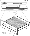
- FIG 2b is an exemplary perspective illustration of one possible filter box 3.
- the filter box 3 When in operational position, the filter box 3 has in this example four substantially vertical sides and two substantially horizontal ends, i.e. the bottom part and the top part.
- One of the side walls is a front panel (F) and the back panel (B) is located at the opposite end as shown in Figure 2b , and the front panel (F) has anopening 13 so that the filtered cutting fluid can be drained through this opening 13 to the clean cutting fluid container.
- Two side walls (S) of the filter box 3 are located to the left and right of the front panel (F).
- the filter box could also incorporate more than one of this type of opening 13.
- the box can also incorporate round ends / sloped faces, depending on specific applications.
- the bottom part has a filtering or filtration element 15, such as a screen (i.e. filter plate screen) or mesh that is arranged to filter the dirty cutting fluid.
- the filtration element 15 is advantageously made of one of a variety of materials, including metals, glass or plastics.
- the other sides of the box 3 are metal, plastic or glass walls that do not allow the cutting fluid to penetrate into the box 3 through these walls. It is to be noted that the number of sides being fitted with the filtration element 15 is not limited to one. Also, instead of the bottom side being fitted with the filtration element 15, any other side could be equally fitted with the filtration element 15.
- the filter plate can be welded in or bolted in.
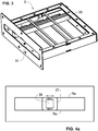
- FIG. 3 shows the filter box 3 of Figure 2b with the filtration element 15 being removed, hence revealing the internal part of the filter box 3.
- a brush 20 is located internal of the the filter unit 3 in order to self cleaning the filtration element 15 from inside out.
- the brushing mechanism showed in this example has a brush 20 that is elongated that is fixed to a moving part 27 (Shown in Fig. 4a-c ). This advantageously allows the brush 20 to move from side (S) to side (S) within the filter unit so that almost the entire region of the filtration element 15 can be cleaned with one or more brush 20.
- at least 95 % of the surface of the filtration element 15 can be cleaned effectively by the brush element 20.
- the cleaning brush 20 can be in any shape such as flat, round, square or have any size and diameter. It is also to be understood that one or more of a wiper, a scraper or a blade can also be used as a brush replacement whereby they produce equally good cleaning effects as well as hydraulic jolt effect similar as to the brush according to the present invention.
- a particular preferred brush has a flat rectangular shape. It is to be noted that the orientation of the brush can be configured in any direction, for instance the brush 20 can be configured to move from front panel (F) to back panel (B), with or without the ability of self rotating.
- the brush element 20 can be mounted in a single or a double configuration in the filter box 3.
- the brush direction is preferably configured parallel to the moving-belt.
- the brush may located at any position, for instance inside or outside of the filter box.
- FIGS 4a-d show cross sectional front views of the filter box 3, wherein different examples of the brush cleaning mechanisms can be employed according to the present invention.
- Figure 4a shows a first example of the brush cleaning mechanism.
- the brush 20 has a large diameter so that the brush is capable of reaching both the top part 15a and bottom part 15b of the filtration element 15 with a single cleaning brush 20.
- the brush in this example is able to move from side (S) to side (S) of the filter box 3.
- Said brush 20 is also capable of rotating in full circle, clock-wise or anti-clockwise while moving from one side to another. This advantageously allows the cleaning mechanism using fewer brush to clean different filtration elements 15a, 15b simultaneously.
- Figure 4b shows another example where two brush elements 20 are mounted on a shared moving part 27.
- the brushes are mounted in a double configuration whereby one brush 20 is cleaning the top part 15a while another brush 20 is cleaning the bottom part 15b of the filtration element 15.
- both the brushes are mounted on a shared moving part 27, the brush is configured to move simultaneously.
- both brushes 20 are capable of rotating in different directions and speed, as discussed in all other examples.
- This example advantageously allows for a better and a more efficient cleaning mechanism to clean the filter box 3.
- the brushes 20 are mounted on the same moving part 27 and hence move simultaneuously in the same direction, they could nonetheless rotate at different directions (clockwise and/or anti-clockwise) as well as speed. This allows for more versatile controls to the brush 20.
- Figure 4c shows a single brush 20 that is mounted on the moving part 27 within the filter box 3.
- the brush 20 is configured to brush the top part 15a of the filtration element 15.
- a single configuration of brush element is useful when there are less cutting chips to be removed from the filtration element 15. It is not only cost-saving, but also reduces the worn-out rate of the filtration element 15 caused by the mechanical scalping by the brush.
- Figure 4d shows yet another example of the brush cleaning mechanism according to one embodiment of the present invention.
- two brushes 20 are mounted on different moving parts 27, hence each brush 20 is controlled separately and hence could move in different directions.
- This example advantageously allows for the brush 20 to be adapted to the specific needs of cleaning the filtration element 15 of the filter box 3. For instance, a faster moving brush 20 may be required to clean the top part 15a of the filtration element 15a which may have more cutting chips to be removed while a slower moving brush 20 may be required to clean the bottom part 15b of the filtration element 15 where relatively fewer cutting chips stuck at the bottom filtration element, or vice versa.
- the brush 20 cleans the filtration element 15 with mechanical force also has a jolt effect as well as a back-flush effect when the brush motion is rapid. These effects additionally allow for a more efficient cleaning on the filtration element 15. Due to the delicate designed of the filtration element 15, the brush 20 used for cleaning the filter box 3 is specially designed in order to avoid damaging the the filtration element 15 while efficient enough to remove the cutting chips from clogging the orifice openings of the filtration element 15. Moreover, the brush 20 according to the present invention uses a controllable mechanical force, such cleaning mechanism proves to be superior compared to other cleaning mechanisms alone such as liquid or gas spray system in removing cutting chips.
- the brush shown in this example apart from moving from side to side to clean the filtration element 15, it could also rotate 360 degrees in different directions, for instance rotating in a clockwise direction, anti-clockwise direction or in an alternative direction. Furthermore, the rotation speed can be varied, depending on the needs of cleaning the filtration element 15. Therefore cutting chips can be removed from clogging the filtration element 15.
- the filter box 3 may further equip with one or more cleaning mechanisms to assist the brush cleaning mechanism.
- the filter box 3 may have an additional internal flush or spray system to emit pressurised water or compressed air towards the filtration element 15 from inside out in order to remove the clogged cutting chips.
- the spray system has a spray bar or pipe, and an internal piping system 22 having distribution hoses connected to the spray pipe.
- Dual, triple or numerous filter element 15 in the same filter unit 3 could be used. Layered filtration to finer and finer levels could also be considered.
- the filter unit(s) can be removably connected or fixed to the tank 5.
- the filter unit 3 could consist of one large box.
- the filter element 15 could also form part of the tank of the conveyor 1.
- the conveyor can also comprise second cleaning means, such as an external cleaning brush, on the inner side of the belt 7 to clean the filter unit 3 while the belt 7 rotates.
- second cleaning means such as an external cleaning brush
- the brushes can be made of synthetic polymer such as nylon, polyester, polystyrene and may be placed in the middle of the flat metal part of the belt, i.e. the part between the hinges. It is also possible for the brushes to be made of other synthetic polymers, metals or combination thereof. Other variations of the disclosed embodiment can be understood and effected by those skilled in the art in practising the claimed invention, from a study of the drawings, the disclosure and the appended claims.
Landscapes
- Chemical & Material Sciences (AREA)
- Chemical Kinetics & Catalysis (AREA)
- Engineering & Computer Science (AREA)
- Mechanical Engineering (AREA)
- Auxiliary Devices For Machine Tools (AREA)
- Filtration Of Liquid (AREA)
Description
- The present invention relates to a filter unit or more specifically a filter box for a chip conveyor for conveying cutting chips that are produced in the operation of a machine tool, such as a lathe or the like. More specifically, the proposed filter unit has at least one internally located brush that is used for removing different types of chips contained in a coolant fluid and/or cutting oil used in machine tools during metal working through mechanical brushing and jolting the surface of the filtration element(s) of the filter unit. The invention equally relates to a corresponding chip conveyor and to a method of filtering cutting fluid in a filtering chip conveyor using the present invention.
- In normal operation, a machine tool, such as a lathe, produces waste material that should be removed from the workpiece being machined. In these cases, the waste material that is removed from the workpiece is generally removed in various sizes including small pieces that are generally referred to as chips. These chips mix with the coolant/cutting oil (hereinafter referred to as cutting fluid) used in the machining process. The cutting fluid can be used for cooling, wash down and/or lubrication, for example. This mixture of cutting fluid and cutting chips enters the conveyor used for removing the chips from the cutting fluid. The cutting chips are thus conveyed from the receiving position to a discharge position.
- The cutting fluid drains through the conveyor to the machine tool oil/coolant reservoir. Some of the chips that are mixed with the cutting fluid also pass into the machine's oil/coolant reservoir with the cutting fluid. These chips eventually build up in the machine oil/coolant reservoir and require manual intervention to clean them out, because the cutting fluid in the reservoir is generally re-circulated for further use. Thus, before the cutting fluid can be recirculated and reused, the waste material produced during the operation of the machine tool first has to be removed.
- Hinge belt conveyors are widely used to convey the chips away from the cutting fluid. This type of conveyor is the most simple of all conveyors on the market, and is widely used throughout the industry. This is a very versatile product in that it is capable of taking any chip shape or size, but has generally one major drawback in that it often does not offer any filtration. This results in small chips passing through the conveyor into the cutting fluid tank which then means that the machine operator has to perform regular maintenance to clean out the tank (duration depending on the specific application).
- However, filtering chip conveyors also exist and self-cleaning scraper conveyors are an example of these kinds of conveyors. They can filter out particles (chips) down to a particle size of around 500 µm (0.5 mm). The minimum dimension of the particles which can be filtered out of the fluid is also referred to as the filtration level. These kinds of conveyors, such as the one disclosed in
WO2004/054756 , typically use a self-cleaning filter box to prevent small chips (larger than the filtration level of the filter screens used) from passing out of the cutting fluid tank and being cycled back into the machine tool. One problem with such self-cleaning scraper conveyors is that they do not generally filter long chips well, especially long chips having a smallest dimension (thickness) similar to the size of the openings in the filter material. Chips are liable to become wedged in the weave of typical woven filtration meshes, and are difficult for the scrapers to dislodge. The mesh becomes clogged, and the fluid flow through the screen, and thereby the filtration performance, is markedly reduced. This is one of the reasons why self-cleaning scraper conveyors are commonly supplemented with a filter drum. This combination is better suited to applications in which a wide variety of various chip sizes and shapes are produced and in which filtration is needed. -
WO2011023233 describes a filtering chip conveyor with a brush for wiping the outside of the filter box. Machines today are capable of many types of machining processes and thus produce a wide range of chip types and shapes. The currently available solutions are either inefficient (with no or poor filtration) or very expensive, due to the complexity of the drum filter and self-cleaning scraper conveyor arrangements required. - It is the aim of the present invention to overcome the problems identified above. More specifically the aim is to provide a solution for filtering chip conveyors so that a high fluid through-flow can be obtained, while at the same time allowing filtration levels down to 50 µm or even lower.
- According to a first aspect of the invention, there is provided a filter unit for a filtering chip conveyor, the filter unit comprising:
- at least one filtration element comprising a filtration region having a plurality of first openings for permitting cutting fluid to pass through the filtration element while not permitting chips with given dimensions to pass through it; and
- at least one second opening allowing cutting fluid inside the filter unit to pass out of the filter unit through the second opening, wherein the filter unit further comprises:
- at least one brush located inside of the filter unit, the brush being arranged to brush the filtration element to remove cutting chips from clogging the filtration element.
- The proposed filter unit has the advantage that the solution is simple, while still allowing efficient cleaning of the filter unit. More specific chips that are usually stuck at the surface of the filtration element can now be mechanically brushed off from the filter element. Moreover, the brush which is considered as an internal cleaning mechanism also provides for a jolt effect when the brush motion is rapid. This means that the filter element is jolted due to the fast-moving and/or the fast rotating motion of the brush element. Thus, the filter unit can be considered as being self-cleaning. This also means that the fluid through-flow can be constantly high. Also filtration of chips with very small dimensions can be achieved. For instance the filtering element can have opening with dimensions smaller than 50 µm.
- The proposed filter unit can also be easily connected to a filtering chip conveyor, which is designed to be a simple filtration conveyor that can handle a multiple range of applications, material and chip types. Furthermore, spray bars are not necessarily needed to clean the filter unit but could be used additionally in enhancing the performance of the conveyor as the brush mechanism proposed herein proves to be superior than spray bars in removing cutting chips from filtration elements.
- According to a second aspect of the invention, there is provided a filtering chip conveyor comprising the filter unit according to the first aspect of the present invention.
- According to a third aspect of the invention, there is provided a method of filtering cutting fluid for a filtering chip conveyor comprising a conveyor tank arranged to retain the cutting fluid containing chips, and further comprising a continuous conveyor belt at least partly disposed inside the conveyor tank, the conveyor belt having upper and lower flights with a filter unit between these flights, wherein the filter unit comprises at least one of a filtration element and a brush located inside of the filter unit, the method comprising:
- the filter unit filtering the cutting fluid entering the filter unit;
- the brush brushes the filtration element to remove cutting chips from clogging the filtration element,
- discharging the filtered cutting fluid off the conveyor through the filter unit,
- discharging the filtered cutting chips through the continuous conveyor belt.
- In one embodiment according to the present invention, the filter unit is a filter box. Such filter box has an advantage of being compactedly built and better fitted into the filtering chip conveyor.
- According to other embodiments of the present invention, the
brush 20 is arranged to move from side to side within the filter unit. This enables almost the entire region of thefiltration element 15 to be cleaned. Furthermore, thebrush 20 is arranged to rotate and perform a translational motion, such as in a clockwise or an anti-clockwise direction. This allows another mechanical forces to be used to clean thefiltration element 15 more efficient. Moreover, different cleaning directions allow for a more efficient cleaning mechanism. Also, the brush is arranged to rotate at a constant speed, but an inconsistent speed can also be used. The speed is important to be adjustable and to be fine-tuned depending on the requirement to remove cutting chips from clogging thefiltration element 15. Thebrush 20 can be made up of at least one of a synthetic polymer, a metal and/or combination thereof. Furthermore, the brush is a quick connection coupling or a fixed connection. The quick connection of thebrush 20 coupling to the movingpart 27 allows for the brush to be changed, while the fixed connection of thebrush 20 allows for an easier construction of thefilter box 3. One ormore brush 20 can be mounted in thefilter box 3, depending on the width of the conveyor and the particular needs and applications. In some embodiments, thefiltration element 15 is a filter mesh. - Other features and advantages of the invention will become apparent from the following description of non-limiting exemplary embodiments, with reference to the appended drawings, in which:
-
Figure 1 is a perspective view of the filtering chip conveyor according to an embodiment of the present invention; -
Figure 2a is a side view of the filtering chip conveyor ofFigure 1 ; -
Figure 2b is a perspective view of a filter unit used for filtering cutting chips in accordance with an embodiment of the present invention; -
Figure 3 is a perspective view of a filter unit ofFigure 2b with the filtration element removed, thereby showing a brush located within the filter unit; -
Figures 4a-d are cross sectional side views of the filter unit showing different examples of the brush cleaning mechanisms according to varies embodiments of the the present invention. - Next an embodiment of the present invention is described in more detail with reference to the attached figures.
-
Figure 1 is a perspective view showing thefiltering chip conveyor 1 comprising the filter unit, in this example afilter box 3, according to one embodiment of the present invention. Theconveyor 1 also comprises a conveyor tank which may have aconveyor frame 5, where the conveyor tank is arranged to retain the dirty cutting fluid resulting from metal working. Aconveyor belt 7, in this case a hinge belt, is at least partly disposed inside theconveyor frame 5. Thehinge belt 7 is formed by connecting a plurality of metal plates with hinges into a continuous or endless caterpillar-type belt. The chips resulting from the metal working are arranged to fall inside the conveyor tank from above, in the direction of the arrow W. - The
hinge belt 7 is arranged to be turned around at tail-end sprocket/disk and discharge end sprockets and rotated as a belt conveyor. In the figures the tail end is referred to by "Te" and the discharge end by "De". Amotor 11 is also shown and is used for rotating thebelt 7. - The path of travel of the belt is substantially horizontal in the lower part of the
conveyor 1, as can be seen in theFigure 2a . As can be seen inFigure 2a , the belt has an upper (reference "U" shown inFigure 2a ) and a lower (reference "L" shown inFigure 2a ) portion substantially parallel to one another in the lower part of theconveyor 1. The upper portion travels in a first direction, whereas the lower portion travels in a second direction, the second direction being opposite to the first direction, in the lower portion of theconveyor 1. The arrow R inFigure 2a shows the direction of rotation of thebelt 7. The upper portion is arranged to carry the large chips to the discharge end De to be discharged off thebelt 7. A chip reservoir (not shown in the figure) is used to store the discharged chips. - In
Figure 2a , there is also shown thefilter box 3 on the inside of the belt, i.e. between the upper U and lower L portions of thebelt 7 for filtering the cutting fluid. By placing thefilter box 3 on the inside of thebelt 7 thefilter box 3 is protected from large chips. There can be one or more boxes linked in the same conveyor depending e.g. on the flow rate required, the amount of cutting fluid used and frequency of cleaning. For instance, if a considerable amount of cutting fluid is needed, then the number and/or size of the orifices of thefilter boxes 3 should be increased. The box(es) could be anywhere in the horizontal load section. As illustrated by the figure, thefilter unit 3 has anopening 13 at the front (F) on the vertical side wall through which the filtered cutting fluid can be drained to a clean cutting fluid reservoir (not shown). From the clean cutting fluid reservoir the filtered cutting fluid can be pumped to the machine tool for reuse. -
Figure 2b is an exemplary perspective illustration of onepossible filter box 3. When in operational position, thefilter box 3 has in this example four substantially vertical sides and two substantially horizontal ends, i.e. the bottom part and the top part. One of the side walls is a front panel (F) and the back panel (B) is located at the opposite end as shown inFigure 2b , and the front panel (F) hasanopening 13 so that the filtered cutting fluid can be drained through thisopening 13 to the clean cutting fluid container. Two side walls (S) of thefilter box 3 are located to the left and right of the front panel (F). The filter box could also incorporate more than one of this type ofopening 13. The box can also incorporate round ends / sloped faces, depending on specific applications. - In this example, the bottom part has a filtering or
filtration element 15, such as a screen (i.e. filter plate screen) or mesh that is arranged to filter the dirty cutting fluid. Thefiltration element 15 is advantageously made of one of a variety of materials, including metals, glass or plastics. The other sides of thebox 3 are metal, plastic or glass walls that do not allow the cutting fluid to penetrate into thebox 3 through these walls. It is to be noted that the number of sides being fitted with thefiltration element 15 is not limited to one. Also, instead of the bottom side being fitted with thefiltration element 15, any other side could be equally fitted with thefiltration element 15. The filter plate can be welded in or bolted in. -
Figure 3 shows thefilter box 3 ofFigure 2b with thefiltration element 15 being removed, hence revealing the internal part of thefilter box 3. Abrush 20 is located internal of the thefilter unit 3 in order to self cleaning thefiltration element 15 from inside out. The brushing mechanism showed in this example has abrush 20 that is elongated that is fixed to a moving part 27 (Shown inFig. 4a-c ). This advantageously allows thebrush 20 to move from side (S) to side (S) within the filter unit so that almost the entire region of thefiltration element 15 can be cleaned with one ormore brush 20. According to one variant of the present invention, at least 95 % of the surface of thefiltration element 15 can be cleaned effectively by thebrush element 20. The cleaningbrush 20 can be in any shape such as flat, round, square or have any size and diameter. It is also to be understood that one or more of a wiper, a scraper or a blade can also be used as a brush replacement whereby they produce equally good cleaning effects as well as hydraulic jolt effect similar as to the brush according to the present invention. A particular preferred brush has a flat rectangular shape. It is to be noted that the orientation of the brush can be configured in any direction, for instance thebrush 20 can be configured to move from front panel (F) to back panel (B), with or without the ability of self rotating. Thebrush element 20 can be mounted in a single or a double configuration in thefilter box 3. The brush direction is preferably configured parallel to the moving-belt. In a yet further embodiment of the present invention, the brush may located at any position, for instance inside or outside of the filter box. -
Figures 4a-d show cross sectional front views of thefilter box 3, wherein different examples of the brush cleaning mechanisms can be employed according to the present invention. -
Figure 4a shows a first example of the brush cleaning mechanism. In this example, thebrush 20 has a large diameter so that the brush is capable of reaching both thetop part 15a andbottom part 15b of thefiltration element 15 with asingle cleaning brush 20. The brush in this example is able to move from side (S) to side (S) of thefilter box 3. Saidbrush 20 is also capable of rotating in full circle, clock-wise or anti-clockwise while moving from one side to another. This advantageously allows the cleaning mechanism using fewer brush to cleandifferent filtration elements -
Figure 4b shows another example where twobrush elements 20 are mounted on a shared movingpart 27. In this example, the brushes are mounted in a double configuration whereby onebrush 20 is cleaning thetop part 15a while anotherbrush 20 is cleaning thebottom part 15b of thefiltration element 15. As both the brushes are mounted on a shared movingpart 27, the brush is configured to move simultaneously. Nevertheless, both brushes 20 are capable of rotating in different directions and speed, as discussed in all other examples. This example advantageously allows for a better and a more efficient cleaning mechanism to clean thefilter box 3. Thebrushes 20 are mounted on the same movingpart 27 and hence move simultaneuously in the same direction, they could nonetheless rotate at different directions (clockwise and/or anti-clockwise) as well as speed. This allows for more versatile controls to thebrush 20. -
Figure 4c shows asingle brush 20 that is mounted on the movingpart 27 within thefilter box 3. In this example, thebrush 20 is configured to brush thetop part 15a of thefiltration element 15. A single configuration of brush element is useful when there are less cutting chips to be removed from thefiltration element 15. It is not only cost-saving, but also reduces the worn-out rate of thefiltration element 15 caused by the mechanical scalping by the brush. -
Figure 4d shows yet another example of the brush cleaning mechanism according to one embodiment of the present invention. In this example, twobrushes 20 are mounted on different movingparts 27, hence eachbrush 20 is controlled separately and hence could move in different directions. This example advantageously allows for thebrush 20 to be adapted to the specific needs of cleaning thefiltration element 15 of thefilter box 3. For instance, a faster movingbrush 20 may be required to clean thetop part 15a of thefiltration element 15a which may have more cutting chips to be removed while a slower movingbrush 20 may be required to clean thebottom part 15b of thefiltration element 15 where relatively fewer cutting chips stuck at the bottom filtration element, or vice versa. - In all examples described above, the
brush 20 cleans thefiltration element 15 with mechanical force also has a jolt effect as well as a back-flush effect when the brush motion is rapid. These effects additionally allow for a more efficient cleaning on thefiltration element 15. Due to the delicate designed of thefiltration element 15, thebrush 20 used for cleaning thefilter box 3 is specially designed in order to avoid damaging the thefiltration element 15 while efficient enough to remove the cutting chips from clogging the orifice openings of thefiltration element 15. Moreover, thebrush 20 according to the present invention uses a controllable mechanical force, such cleaning mechanism proves to be superior compared to other cleaning mechanisms alone such as liquid or gas spray system in removing cutting chips. The brush shown in this example, apart from moving from side to side to clean thefiltration element 15, it could also rotate 360 degrees in different directions, for instance rotating in a clockwise direction, anti-clockwise direction or in an alternative direction. Furthermore, the rotation speed can be varied, depending on the needs of cleaning thefiltration element 15. Therefore cutting chips can be removed from clogging thefiltration element 15. - In a further embodiment, the
filter box 3 may further equip with one or more cleaning mechanisms to assist the brush cleaning mechanism. For instance, thefilter box 3 may have an additional internal flush or spray system to emit pressurised water or compressed air towards thefiltration element 15 from inside out in order to remove the clogged cutting chips. The spray system has a spray bar or pipe, and an internal piping system 22 having distribution hoses connected to the spray pipe. - While the invention has been illustrated and described in detail in the drawings and foregoing description, such illustration and description are to be considered illustrative or exemplary and not restrictive, the invention being not restricted to the disclosed embodiment. Dual, triple or
numerous filter element 15 in thesame filter unit 3 could be used. Layered filtration to finer and finer levels could also be considered. The filter unit(s) can be removably connected or fixed to thetank 5. Thefilter unit 3 could consist of one large box. Furthermore, thefilter element 15 could also form part of the tank of theconveyor 1. Moreover, the conveyor can also comprise second cleaning means, such as an external cleaning brush, on the inner side of thebelt 7 to clean thefilter unit 3 while thebelt 7 rotates. Thus, the natural rotation of thebelt 7 can be used for cleaning thefilter unit 3. The brushes can be made of synthetic polymer such as nylon, polyester, polystyrene and may be placed in the middle of the flat metal part of the belt, i.e. the part between the hinges. It is also possible for the brushes to be made of other synthetic polymers, metals or combination thereof. Other variations of the disclosed embodiment can be understood and effected by those skilled in the art in practising the claimed invention, from a study of the drawings, the disclosure and the appended claims. - In the claims, the word "comprising" does not exclude other elements or steps, and the indefinite article "a" or "an" does not exclude a plurality. A single unit may fulfil the functions of several items recited in the claims. The mere fact that different features are recited in mutually different dependent claims does not indicate that a combination of these features cannot be advantageously used. Any reference signs in the claims should not be construed as limiting the scope of the invention.
Claims (11)
- A filter unit (3) for a filtering chip conveyor (1), the filter unit (3) comprising:- at least one filtration element (15) comprising a filtration region having a plurality of first openings for permitting cutting fluid to pass through the filtration element (15) while not permitting chips with given dimensions to pass through it; and- at least one second opening (13) allowing cutting fluid inside the filter unit (3) to pass out of the filter unit (3) through the second opening (13), characterised in that the filter unit (13) further comprises:- at least one brush (20) located inside of the filter unit (3), the brush (20) being arranged to brush the filtration element (15) to remove cutting chips from clogging the filtration element (15).
- A filter unit (3) according to claim 1, wherein the filter unit (3) is a filter box (3).
- A filter unit (3) according to claim 1 or claim 2, wherein the brush (20) being arranged to move from side (S) to side (S) within the filter unit (3).
- A filter unit (3) according to any one of the preceding claims, wherein the brush (20) being arranged to rotate and perform a translational motion.
- A filter unit (3) according to claim 4, wherein the brush (20) being arranged to rotate at a constant or inconsistent speed.
- A filter unit (3) according to any one of the preceding claims, wherein the brush (20) is made of at least one of a synthetic polymer, a metal and/or combination thereof.
- A filter unit (3) according to any one of the preceding claims, wherein the brush (20) is a quick connection coupling or a fixed connection.
- A filter unit (3) according to any one of the preceding claims, wherein the filtration element (15) is a filter mesh.
- A filtering chip conveyor (1) comprising the filter unit (3) according to any one of the preceding claims.
- A filtering chip conveyor (1) according to claim 9 further comprising:- a conveyor tank arranged to retain cutting fluid containing chips;- a continuous conveyor belt (7) at least partly disposed inside the conveyor tank, the belt (7) being arranged to rotate and to turn at a tail end (Te) and at a discharge end (De), with a space between upper (U) and lower flights (L) of the belt (7), so as to transport chips on the upper flight (U) towards the discharge end (De), to be discharged off the conveyor (1),wherein the filter box (3) is arranged between the upper (U) and the lower (L) flights of the belt (7).
- A method of filtering cutting fluid in a filtering chip conveyor (1) comprising a conveyor tank arranged to retain the cutting fluid containing chips, and further comprising a continuous conveyor belt (7) at least partly disposed inside the conveyor tank, the conveyor belt having upper (U) and lower flights (L) with a filter unit (3) between these flights, wherein the filter unit (3) comprises a brush (20) located inside of the filter unit (3) and a filtration element (15), the method comprising:- the filter unit (3) filters the cutting fluid entering the filter unit (3);- the brush (20) brushes the filtration element (15) to remove cutting chips from clogging the filtration element (15).- discharging the filtered cutting fluid off the conveyor (1) through the filter unit (3).- discharging the filtered cutting chips through the continuous conveyor belt (7).
Priority Applications (1)
| Application Number | Priority Date | Filing Date | Title |
|---|---|---|---|
| PL16159920T PL3067104T3 (en) | 2015-03-12 | 2016-03-11 | Filtering unit for a filtering chip conveyor |
Applications Claiming Priority (1)
| Application Number | Priority Date | Filing Date | Title |
|---|---|---|---|
| CH3412015 | 2015-03-12 |
Publications (2)
| Publication Number | Publication Date |
|---|---|
| EP3067104A1 EP3067104A1 (en) | 2016-09-14 |
| EP3067104B1 true EP3067104B1 (en) | 2018-06-27 |
Family
ID=54065134
Family Applications (1)
| Application Number | Title | Priority Date | Filing Date |
|---|---|---|---|
| EP16159920.4A Active EP3067104B1 (en) | 2015-03-12 | 2016-03-11 | Filtering unit for a filtering chip conveyor |
Country Status (8)
| Country | Link |
|---|---|
| US (1) | US10376821B2 (en) |
| EP (1) | EP3067104B1 (en) |
| JP (1) | JP6738168B2 (en) |
| CN (1) | CN105965314B (en) |
| ES (1) | ES2685428T3 (en) |
| PL (1) | PL3067104T3 (en) |
| TR (1) | TR201810662T4 (en) |
| TW (1) | TWI675695B (en) |
Families Citing this family (14)
| Publication number | Priority date | Publication date | Assignee | Title |
|---|---|---|---|---|
| US20200078894A1 (en) * | 2018-09-07 | 2020-03-12 | Manufacturing Productivity Systems | Coolant filtration system |
| KR102201423B1 (en) * | 2018-12-17 | 2021-01-11 | 강수동 | High efficiency cutting oil filtering device |
| JP6751790B1 (en) * | 2019-03-15 | 2020-09-09 | Dmg森精機株式会社 | Machine tool chip processing equipment and chip processing method |
| CN110013711B (en) * | 2019-03-25 | 2024-04-16 | 淮北矿业股份有限公司 | Filter residue device of gas extraction system convenient to clean |
| CN110539215A (en) * | 2019-08-28 | 2019-12-06 | 大同新成新材料股份有限公司 | Grinding device and method for outer circle of carbon felt heat-insulating cylinder |
| CN110497242B (en) * | 2019-09-28 | 2020-04-28 | 滕州市山东大汉智能科技有限公司 | Digit control machine tool cutting waste recovery device |
| US10994936B1 (en) | 2019-12-18 | 2021-05-04 | Mayfran Limburg B.V. | Inner cleaning system for endless belt conveyor |
| CN111283468B (en) * | 2020-04-07 | 2021-03-19 | 广州赢帝工业设计有限公司 | Automatic drilling equipment of watchband |
| CN111991864A (en) * | 2020-08-26 | 2020-11-27 | 泉州方科昌耀工业设计有限公司 | Hydraulic engineering's filth environmental protection collection device |
| CN112496396B (en) * | 2020-12-15 | 2022-09-06 | 湖南鑫辉科技发展有限公司 | Heat dissipation base assembling equipment for CPU radiator |
| CN114367868B (en) * | 2022-02-18 | 2022-11-29 | 常州机电职业技术学院 | Filter equipment for digit control machine tool |
| CN114643494B (en) * | 2022-05-19 | 2022-08-12 | 昆山台功精密机械有限公司 | Cooling liquid circulation system for numerical control machining center |
| CN115213727B (en) * | 2022-09-20 | 2023-01-03 | 江苏宏达数控科技股份有限公司 | Numerical control machine tool workbench |
| CN115922104B (en) * | 2022-11-29 | 2024-05-28 | 萍乡市福瑞精密机械有限公司 | Sheet metal part laser cutting and blanking equipment and cutting process thereof |
Family Cites Families (16)
| Publication number | Priority date | Publication date | Assignee | Title |
|---|---|---|---|---|
| US3464557A (en) * | 1966-12-12 | 1969-09-02 | Bowser Inc | Movable filter and magnetic sealing means |
| US3554379A (en) * | 1969-06-10 | 1971-01-12 | Du Pont | Desalination apparatus and process of manufacture using improved, nitrogenous membranes |
| IL40046A (en) * | 1972-08-03 | 1976-03-31 | Evron Kibbutz Hashomer Hatzair | Self cleaning filter |
| JP3510611B2 (en) * | 2001-11-21 | 2004-03-29 | 椿本メイフラン株式会社 | Chip conveying conveyor device with separation function |
| TW549302U (en) * | 2001-12-04 | 2003-08-21 | Fongei Industry Co Ltd | Conveying apparatus for metal bits |
| US6888539B2 (en) * | 2002-08-27 | 2005-05-03 | General Electric Company | Business methods and hardware to implement same |
| TWM346446U (en) * | 2008-06-03 | 2008-12-11 | Ying Shuen Machinery Repairing Co Ltd R | Improved structure of conveyor for delivering the cutting scrap |
| WO2011023233A1 (en) * | 2009-08-27 | 2011-03-03 | Lns S.A. | Filtering chip conveyor |
| CN201603460U (en) * | 2010-01-29 | 2010-10-13 | 无锡徐氏数控机床部件有限公司 | Wedge screen device for machine tool |
| JP2011257548A (en) * | 2010-06-08 | 2011-12-22 | Sanyo Electric Co Ltd | Air filter device and projection type image display apparatus using the same |
| PL2629871T3 (en) * | 2010-10-22 | 2016-08-31 | Gala Inc | Filtration device |
| CA2825531A1 (en) * | 2011-03-03 | 2012-09-07 | Lns Management Sa | Filtering chip conveyor |
| KR20140020539A (en) * | 2012-08-09 | 2014-02-19 | 주식회사 블루웨일스크린 | Inclined mesh panel type filtering apparatus |
| CN202860244U (en) * | 2012-09-04 | 2013-04-10 | 烟台开发区博森科技发展有限公司 | Conveyer belt type cyclic filtration device |
| CN202962044U (en) * | 2012-11-26 | 2013-06-05 | 余姚市舜江机械实业有限公司 | Solid-liquid separation filter |
| WO2014177199A1 (en) | 2013-04-30 | 2014-11-06 | Lns Management Sa | Filter box for a filtering chip conveyor |
-
2015
- 2015-09-11 US US14/851,023 patent/US10376821B2/en active Active
-
2016
- 2016-03-11 EP EP16159920.4A patent/EP3067104B1/en active Active
- 2016-03-11 PL PL16159920T patent/PL3067104T3/en unknown
- 2016-03-11 TW TW105107562A patent/TWI675695B/en active
- 2016-03-11 TR TR2018/10662T patent/TR201810662T4/en unknown
- 2016-03-11 ES ES16159920.4T patent/ES2685428T3/en active Active
- 2016-03-11 JP JP2016048362A patent/JP6738168B2/en active Active
- 2016-03-11 CN CN201610255190.0A patent/CN105965314B/en active Active
Non-Patent Citations (1)
| Title |
|---|
| None * |
Also Published As
| Publication number | Publication date |
|---|---|
| PL3067104T3 (en) | 2018-12-31 |
| US10376821B2 (en) | 2019-08-13 |
| JP6738168B2 (en) | 2020-08-12 |
| CN105965314A (en) | 2016-09-28 |
| TR201810662T4 (en) | 2018-08-27 |
| EP3067104A1 (en) | 2016-09-14 |
| TWI675695B (en) | 2019-11-01 |
| TW201637703A (en) | 2016-11-01 |
| CN105965314B (en) | 2021-04-30 |
| ES2685428T3 (en) | 2018-10-09 |
| JP2016215186A (en) | 2016-12-22 |
| US20160263500A1 (en) | 2016-09-15 |
Similar Documents
| Publication | Publication Date | Title |
|---|---|---|
| US10376821B2 (en) | Filtering unit for a filtering chip conveyor | |
| US20140054244A1 (en) | Filtering chip conveyor | |
| WO2014177199A1 (en) | Filter box for a filtering chip conveyor | |
| CN111093796B (en) | Filter device | |
| JPH0866607A (en) | Fractional filtration method and fractional filter | |
| CN114832489B (en) | Industrial sewage purifying treatment system | |
| US20030010723A1 (en) | Media vacuum filter | |
| WO2011023233A1 (en) | Filtering chip conveyor | |
| US20060049112A1 (en) | Coolant fluid cleaning method, system, and apparatus | |
| KR101574411B1 (en) | Reciprocating scraper apparatus in screen equipment for separation of solid materials from slurry | |
| JP2015226943A (en) | Chip conveyor for machine tool | |
| JP2012091311A (en) | Chip conveyor device | |
| KR101387714B1 (en) | Oil filtering apparatus | |
| JP5240877B2 (en) | Filtration method, filter, and chip conveyor apparatus equipped with the filter | |
| JP2010142716A (en) | Filtration equipment | |
| JP2008055533A (en) | Chip carrying conveyor device | |
| JP6767823B2 (en) | Conveyor conveyor and chip conveyor equipment | |
| JP4896185B2 (en) | Machine tool coolant treatment equipment | |
| JP2007083105A (en) | Filtering device | |
| KR101992435B1 (en) | Micro chip separator using filter drum and scraper | |
| JP2003326436A (en) | Cutting fluid filtering device | |
| DE20114853U1 (en) | Device for separating and removing chips | |
| CN105797461A (en) | Anti-blocking garbage filtering sieve | |
| CN212759114U (en) | Magnetic rod dirt scraping mechanism in horizontal magnetic rod filter | |
| DE3909970C2 (en) | Device for the filtration of liquids, in particular waste water in the manner of a quick filter |
Legal Events
| Date | Code | Title | Description |
|---|---|---|---|
| PUAI | Public reference made under article 153(3) epc to a published international application that has entered the european phase |
Free format text: ORIGINAL CODE: 0009012 |
|
| AK | Designated contracting states |
Kind code of ref document: A1 Designated state(s): AL AT BE BG CH CY CZ DE DK EE ES FI FR GB GR HR HU IE IS IT LI LT LU LV MC MK MT NL NO PL PT RO RS SE SI SK SM TR |
|
| AX | Request for extension of the european patent |
Extension state: BA ME |
|
| STAA | Information on the status of an ep patent application or granted ep patent |
Free format text: STATUS: REQUEST FOR EXAMINATION WAS MADE |
|
| 17P | Request for examination filed |
Effective date: 20170126 |
|
| RBV | Designated contracting states (corrected) |
Designated state(s): AL AT BE BG CH CY CZ DE DK EE ES FI FR GB GR HR HU IE IS IT LI LT LU LV MC MK MT NL NO PL PT RO RS SE SI SK SM TR |
|
| GRAP | Despatch of communication of intention to grant a patent |
Free format text: ORIGINAL CODE: EPIDOSNIGR1 |
|
| STAA | Information on the status of an ep patent application or granted ep patent |
Free format text: STATUS: GRANT OF PATENT IS INTENDED |
|
| RIC1 | Information provided on ipc code assigned before grant |
Ipc: B01D 29/33 20060101ALI20180226BHEP Ipc: B01D 29/64 20060101ALI20180226BHEP Ipc: B01D 29/00 20060101AFI20180226BHEP |
|
| INTG | Intention to grant announced |
Effective date: 20180322 |
|
| GRAS | Grant fee paid |
Free format text: ORIGINAL CODE: EPIDOSNIGR3 |
|
| GRAA | (expected) grant |
Free format text: ORIGINAL CODE: 0009210 |
|
| STAA | Information on the status of an ep patent application or granted ep patent |
Free format text: STATUS: THE PATENT HAS BEEN GRANTED |
|
| AK | Designated contracting states |
Kind code of ref document: B1 Designated state(s): AL AT BE BG CH CY CZ DE DK EE ES FI FR GB GR HR HU IE IS IT LI LT LU LV MC MK MT NL NO PL PT RO RS SE SI SK SM TR |
|
| REG | Reference to a national code |
Ref country code: GB Ref legal event code: FG4D |
|
| REG | Reference to a national code |
Ref country code: CH Ref legal event code: NV Representative=s name: BOVARD AG PATENT- UND MARKENANWAELTE, CH |
|
| REG | Reference to a national code |
Ref country code: AT Ref legal event code: REF Ref document number: 1011793 Country of ref document: AT Kind code of ref document: T Effective date: 20180715 |
|
| REG | Reference to a national code |
Ref country code: IE Ref legal event code: FG4D |
|
| REG | Reference to a national code |
Ref country code: DE Ref legal event code: R096 Ref document number: 602016003757 Country of ref document: DE |
|
| REG | Reference to a national code |
Ref country code: SE Ref legal event code: TRGR |
|
| REG | Reference to a national code |
Ref country code: NL Ref legal event code: FP |
|
| REG | Reference to a national code |
Ref country code: ES Ref legal event code: FG2A Ref document number: 2685428 Country of ref document: ES Kind code of ref document: T3 Effective date: 20181009 |
|
| PG25 | Lapsed in a contracting state [announced via postgrant information from national office to epo] |
Ref country code: FI Free format text: LAPSE BECAUSE OF FAILURE TO SUBMIT A TRANSLATION OF THE DESCRIPTION OR TO PAY THE FEE WITHIN THE PRESCRIBED TIME-LIMIT Effective date: 20180627 Ref country code: BG Free format text: LAPSE BECAUSE OF FAILURE TO SUBMIT A TRANSLATION OF THE DESCRIPTION OR TO PAY THE FEE WITHIN THE PRESCRIBED TIME-LIMIT Effective date: 20180927 Ref country code: LT Free format text: LAPSE BECAUSE OF FAILURE TO SUBMIT A TRANSLATION OF THE DESCRIPTION OR TO PAY THE FEE WITHIN THE PRESCRIBED TIME-LIMIT Effective date: 20180627 Ref country code: NO Free format text: LAPSE BECAUSE OF FAILURE TO SUBMIT A TRANSLATION OF THE DESCRIPTION OR TO PAY THE FEE WITHIN THE PRESCRIBED TIME-LIMIT Effective date: 20180927 |
|
| REG | Reference to a national code |
Ref country code: LT Ref legal event code: MG4D |
|
| PG25 | Lapsed in a contracting state [announced via postgrant information from national office to epo] |
Ref country code: GR Free format text: LAPSE BECAUSE OF FAILURE TO SUBMIT A TRANSLATION OF THE DESCRIPTION OR TO PAY THE FEE WITHIN THE PRESCRIBED TIME-LIMIT Effective date: 20180928 Ref country code: LV Free format text: LAPSE BECAUSE OF FAILURE TO SUBMIT A TRANSLATION OF THE DESCRIPTION OR TO PAY THE FEE WITHIN THE PRESCRIBED TIME-LIMIT Effective date: 20180627 Ref country code: HR Free format text: LAPSE BECAUSE OF FAILURE TO SUBMIT A TRANSLATION OF THE DESCRIPTION OR TO PAY THE FEE WITHIN THE PRESCRIBED TIME-LIMIT Effective date: 20180627 Ref country code: RS Free format text: LAPSE BECAUSE OF FAILURE TO SUBMIT A TRANSLATION OF THE DESCRIPTION OR TO PAY THE FEE WITHIN THE PRESCRIBED TIME-LIMIT Effective date: 20180627 |
|
| REG | Reference to a national code |
Ref country code: AT Ref legal event code: MK05 Ref document number: 1011793 Country of ref document: AT Kind code of ref document: T Effective date: 20180627 |
|
| PG25 | Lapsed in a contracting state [announced via postgrant information from national office to epo] |
Ref country code: RO Free format text: LAPSE BECAUSE OF FAILURE TO SUBMIT A TRANSLATION OF THE DESCRIPTION OR TO PAY THE FEE WITHIN THE PRESCRIBED TIME-LIMIT Effective date: 20180627 Ref country code: SK Free format text: LAPSE BECAUSE OF FAILURE TO SUBMIT A TRANSLATION OF THE DESCRIPTION OR TO PAY THE FEE WITHIN THE PRESCRIBED TIME-LIMIT Effective date: 20180627 Ref country code: EE Free format text: LAPSE BECAUSE OF FAILURE TO SUBMIT A TRANSLATION OF THE DESCRIPTION OR TO PAY THE FEE WITHIN THE PRESCRIBED TIME-LIMIT Effective date: 20180627 Ref country code: AT Free format text: LAPSE BECAUSE OF FAILURE TO SUBMIT A TRANSLATION OF THE DESCRIPTION OR TO PAY THE FEE WITHIN THE PRESCRIBED TIME-LIMIT Effective date: 20180627 Ref country code: IS Free format text: LAPSE BECAUSE OF FAILURE TO SUBMIT A TRANSLATION OF THE DESCRIPTION OR TO PAY THE FEE WITHIN THE PRESCRIBED TIME-LIMIT Effective date: 20181027 |
|
| PG25 | Lapsed in a contracting state [announced via postgrant information from national office to epo] |
Ref country code: SM Free format text: LAPSE BECAUSE OF FAILURE TO SUBMIT A TRANSLATION OF THE DESCRIPTION OR TO PAY THE FEE WITHIN THE PRESCRIBED TIME-LIMIT Effective date: 20180627 |
|
| REG | Reference to a national code |
Ref country code: DE Ref legal event code: R097 Ref document number: 602016003757 Country of ref document: DE |
|
| PLBE | No opposition filed within time limit |
Free format text: ORIGINAL CODE: 0009261 |
|
| STAA | Information on the status of an ep patent application or granted ep patent |
Free format text: STATUS: NO OPPOSITION FILED WITHIN TIME LIMIT |
|
| PG25 | Lapsed in a contracting state [announced via postgrant information from national office to epo] |
Ref country code: DK Free format text: LAPSE BECAUSE OF FAILURE TO SUBMIT A TRANSLATION OF THE DESCRIPTION OR TO PAY THE FEE WITHIN THE PRESCRIBED TIME-LIMIT Effective date: 20180627 |
|
| 26N | No opposition filed |
Effective date: 20190328 |
|
| PG25 | Lapsed in a contracting state [announced via postgrant information from national office to epo] |
Ref country code: SI Free format text: LAPSE BECAUSE OF FAILURE TO SUBMIT A TRANSLATION OF THE DESCRIPTION OR TO PAY THE FEE WITHIN THE PRESCRIBED TIME-LIMIT Effective date: 20180627 |
|
| PG25 | Lapsed in a contracting state [announced via postgrant information from national office to epo] |
Ref country code: MC Free format text: LAPSE BECAUSE OF FAILURE TO SUBMIT A TRANSLATION OF THE DESCRIPTION OR TO PAY THE FEE WITHIN THE PRESCRIBED TIME-LIMIT Effective date: 20180627 |
|
| PG25 | Lapsed in a contracting state [announced via postgrant information from national office to epo] |
Ref country code: AL Free format text: LAPSE BECAUSE OF FAILURE TO SUBMIT A TRANSLATION OF THE DESCRIPTION OR TO PAY THE FEE WITHIN THE PRESCRIBED TIME-LIMIT Effective date: 20180627 Ref country code: LU Free format text: LAPSE BECAUSE OF NON-PAYMENT OF DUE FEES Effective date: 20190311 |
|
| REG | Reference to a national code |
Ref country code: BE Ref legal event code: MM Effective date: 20190331 |
|
| PG25 | Lapsed in a contracting state [announced via postgrant information from national office to epo] |
Ref country code: IE Free format text: LAPSE BECAUSE OF NON-PAYMENT OF DUE FEES Effective date: 20190311 |
|
| PG25 | Lapsed in a contracting state [announced via postgrant information from national office to epo] |
Ref country code: BE Free format text: LAPSE BECAUSE OF NON-PAYMENT OF DUE FEES Effective date: 20190331 |
|
| PG25 | Lapsed in a contracting state [announced via postgrant information from national office to epo] |
Ref country code: PT Free format text: LAPSE BECAUSE OF FAILURE TO SUBMIT A TRANSLATION OF THE DESCRIPTION OR TO PAY THE FEE WITHIN THE PRESCRIBED TIME-LIMIT Effective date: 20181029 Ref country code: MT Free format text: LAPSE BECAUSE OF NON-PAYMENT OF DUE FEES Effective date: 20190311 |
|
| PG25 | Lapsed in a contracting state [announced via postgrant information from national office to epo] |
Ref country code: CY Free format text: LAPSE BECAUSE OF FAILURE TO SUBMIT A TRANSLATION OF THE DESCRIPTION OR TO PAY THE FEE WITHIN THE PRESCRIBED TIME-LIMIT Effective date: 20180627 |
|
| PG25 | Lapsed in a contracting state [announced via postgrant information from national office to epo] |
Ref country code: HU Free format text: LAPSE BECAUSE OF FAILURE TO SUBMIT A TRANSLATION OF THE DESCRIPTION OR TO PAY THE FEE WITHIN THE PRESCRIBED TIME-LIMIT; INVALID AB INITIO Effective date: 20160311 |
|
| PG25 | Lapsed in a contracting state [announced via postgrant information from national office to epo] |
Ref country code: MK Free format text: LAPSE BECAUSE OF FAILURE TO SUBMIT A TRANSLATION OF THE DESCRIPTION OR TO PAY THE FEE WITHIN THE PRESCRIBED TIME-LIMIT Effective date: 20180627 |
|
| P01 | Opt-out of the competence of the unified patent court (upc) registered |
Effective date: 20230527 |
|
| PGFP | Annual fee paid to national office [announced via postgrant information from national office to epo] |
Ref country code: ES Payment date: 20250429 Year of fee payment: 10 |
|
| PGFP | Annual fee paid to national office [announced via postgrant information from national office to epo] |
Ref country code: CH Payment date: 20250401 Year of fee payment: 10 |
|
| REG | Reference to a national code |
Ref country code: CH Ref legal event code: U11 Free format text: ST27 STATUS EVENT CODE: U-0-0-U10-U11 (AS PROVIDED BY THE NATIONAL OFFICE) Effective date: 20260401 |
|
| PGFP | Annual fee paid to national office [announced via postgrant information from national office to epo] |
Ref country code: SE Payment date: 20260319 Year of fee payment: 11 |
|
| PGFP | Annual fee paid to national office [announced via postgrant information from national office to epo] |
Ref country code: GB Payment date: 20260324 Year of fee payment: 11 |
|
| PGFP | Annual fee paid to national office [announced via postgrant information from national office to epo] |
Ref country code: DE Payment date: 20260319 Year of fee payment: 11 |
|
| PGFP | Annual fee paid to national office [announced via postgrant information from national office to epo] |
Ref country code: IT Payment date: 20260320 Year of fee payment: 11 |
|
| PGFP | Annual fee paid to national office [announced via postgrant information from national office to epo] |
Ref country code: NL Payment date: 20260319 Year of fee payment: 11 |
|
| PGFP | Annual fee paid to national office [announced via postgrant information from national office to epo] |
Ref country code: FR Payment date: 20260320 Year of fee payment: 11 |
|
| PGFP | Annual fee paid to national office [announced via postgrant information from national office to epo] |
Ref country code: TR Payment date: 20260304 Year of fee payment: 11 |
|
| PGFP | Annual fee paid to national office [announced via postgrant information from national office to epo] |
Ref country code: CZ Payment date: 20260306 Year of fee payment: 11 |
|
| PGFP | Annual fee paid to national office [announced via postgrant information from national office to epo] |
Ref country code: PL Payment date: 20260227 Year of fee payment: 11 |