EP3066232B1 - Damage mitigation for gearbox - Google Patents
Damage mitigation for gearbox Download PDFInfo
- Publication number
- EP3066232B1 EP3066232B1 EP14879970.3A EP14879970A EP3066232B1 EP 3066232 B1 EP3066232 B1 EP 3066232B1 EP 14879970 A EP14879970 A EP 14879970A EP 3066232 B1 EP3066232 B1 EP 3066232B1
- Authority
- EP
- European Patent Office
- Prior art keywords
- component
- gearbox housing
- structural deposit
- housing
- corrosion
- Prior art date
- Legal status (The legal status is an assumption and is not a legal conclusion. Google has not performed a legal analysis and makes no representation as to the accuracy of the status listed.)
- Active
Links
Images




Classifications
-
- F—MECHANICAL ENGINEERING; LIGHTING; HEATING; WEAPONS; BLASTING
- F16—ENGINEERING ELEMENTS AND UNITS; GENERAL MEASURES FOR PRODUCING AND MAINTAINING EFFECTIVE FUNCTIONING OF MACHINES OR INSTALLATIONS; THERMAL INSULATION IN GENERAL
- F16H—GEARING
- F16H57/00—General details of gearing
- F16H57/02—Gearboxes; Mounting gearing therein
-
- B—PERFORMING OPERATIONS; TRANSPORTING
- B64—AIRCRAFT; AVIATION; COSMONAUTICS
- B64F—GROUND OR AIRCRAFT-CARRIER-DECK INSTALLATIONS SPECIALLY ADAPTED FOR USE IN CONNECTION WITH AIRCRAFT; DESIGNING, MANUFACTURING, ASSEMBLING, CLEANING, MAINTAINING OR REPAIRING AIRCRAFT, NOT OTHERWISE PROVIDED FOR; HANDLING, TRANSPORTING, TESTING OR INSPECTING AIRCRAFT COMPONENTS, NOT OTHERWISE PROVIDED FOR
- B64F5/00—Designing, manufacturing, assembling, cleaning, maintaining or repairing aircraft, not otherwise provided for; Handling, transporting, testing or inspecting aircraft components, not otherwise provided for
- B64F5/40—Maintaining or repairing aircraft
-
- C—CHEMISTRY; METALLURGY
- C23—COATING METALLIC MATERIAL; COATING MATERIAL WITH METALLIC MATERIAL; CHEMICAL SURFACE TREATMENT; DIFFUSION TREATMENT OF METALLIC MATERIAL; COATING BY VACUUM EVAPORATION, BY SPUTTERING, BY ION IMPLANTATION OR BY CHEMICAL VAPOUR DEPOSITION, IN GENERAL; INHIBITING CORROSION OF METALLIC MATERIAL OR INCRUSTATION IN GENERAL
- C23C—COATING METALLIC MATERIAL; COATING MATERIAL WITH METALLIC MATERIAL; SURFACE TREATMENT OF METALLIC MATERIAL BY DIFFUSION INTO THE SURFACE, BY CHEMICAL CONVERSION OR SUBSTITUTION; COATING BY VACUUM EVAPORATION, BY SPUTTERING, BY ION IMPLANTATION OR BY CHEMICAL VAPOUR DEPOSITION, IN GENERAL
- C23C24/00—Coating starting from inorganic powder
- C23C24/02—Coating starting from inorganic powder by application of pressure only
- C23C24/04—Impact or kinetic deposition of particles
-
- F—MECHANICAL ENGINEERING; LIGHTING; HEATING; WEAPONS; BLASTING
- F16—ENGINEERING ELEMENTS AND UNITS; GENERAL MEASURES FOR PRODUCING AND MAINTAINING EFFECTIVE FUNCTIONING OF MACHINES OR INSTALLATIONS; THERMAL INSULATION IN GENERAL
- F16H—GEARING
- F16H57/00—General details of gearing
- F16H57/02—Gearboxes; Mounting gearing therein
- F16H57/032—Gearboxes; Mounting gearing therein characterised by the materials used
-
- B—PERFORMING OPERATIONS; TRANSPORTING
- B22—CASTING; POWDER METALLURGY
- B22F—WORKING METALLIC POWDER; MANUFACTURE OF ARTICLES FROM METALLIC POWDER; MAKING METALLIC POWDER; APPARATUS OR DEVICES SPECIALLY ADAPTED FOR METALLIC POWDER
- B22F3/00—Manufacture of workpieces or articles from metallic powder characterised by the manner of compacting or sintering; Apparatus specially adapted therefor ; Presses and furnaces
- B22F3/24—After-treatment of workpieces or articles
- B22F2003/248—Thermal after-treatment
-
- B—PERFORMING OPERATIONS; TRANSPORTING
- B64—AIRCRAFT; AVIATION; COSMONAUTICS
- B64D—EQUIPMENT FOR FITTING IN OR TO AIRCRAFT; FLIGHT SUITS; PARACHUTES; ARRANGEMENT OR MOUNTING OF POWER PLANTS OR PROPULSION TRANSMISSIONS IN AIRCRAFT
- B64D45/00—Aircraft indicators or protectors not otherwise provided for
- B64D2045/009—Fire detection or protection; Erosion protection, e.g. from airborne particles
-
- F—MECHANICAL ENGINEERING; LIGHTING; HEATING; WEAPONS; BLASTING
- F16—ENGINEERING ELEMENTS AND UNITS; GENERAL MEASURES FOR PRODUCING AND MAINTAINING EFFECTIVE FUNCTIONING OF MACHINES OR INSTALLATIONS; THERMAL INSULATION IN GENERAL
- F16H—GEARING
- F16H57/00—General details of gearing
- F16H57/02—Gearboxes; Mounting gearing therein
- F16H2057/02039—Gearboxes for particular applications
-
- Y—GENERAL TAGGING OF NEW TECHNOLOGICAL DEVELOPMENTS; GENERAL TAGGING OF CROSS-SECTIONAL TECHNOLOGIES SPANNING OVER SEVERAL SECTIONS OF THE IPC; TECHNICAL SUBJECTS COVERED BY FORMER USPC CROSS-REFERENCE ART COLLECTIONS [XRACs] AND DIGESTS
- Y10—TECHNICAL SUBJECTS COVERED BY FORMER USPC
- Y10T—TECHNICAL SUBJECTS COVERED BY FORMER US CLASSIFICATION
- Y10T29/00—Metal working
- Y10T29/49—Method of mechanical manufacture
- Y10T29/49616—Structural member making
- Y10T29/49622—Vehicular structural member making
-
- Y—GENERAL TAGGING OF NEW TECHNOLOGICAL DEVELOPMENTS; GENERAL TAGGING OF CROSS-SECTIONAL TECHNOLOGIES SPANNING OVER SEVERAL SECTIONS OF THE IPC; TECHNICAL SUBJECTS COVERED BY FORMER USPC CROSS-REFERENCE ART COLLECTIONS [XRACs] AND DIGESTS
- Y10—TECHNICAL SUBJECTS COVERED BY FORMER USPC
- Y10T—TECHNICAL SUBJECTS COVERED BY FORMER US CLASSIFICATION
- Y10T29/00—Metal working
- Y10T29/49—Method of mechanical manufacture
- Y10T29/49718—Repairing
- Y10T29/49732—Repairing by attaching repair preform, e.g., remaking, restoring, or patching
- Y10T29/49734—Repairing by attaching repair preform, e.g., remaking, restoring, or patching and removing damaged material
-
- Y—GENERAL TAGGING OF NEW TECHNOLOGICAL DEVELOPMENTS; GENERAL TAGGING OF CROSS-SECTIONAL TECHNOLOGIES SPANNING OVER SEVERAL SECTIONS OF THE IPC; TECHNICAL SUBJECTS COVERED BY FORMER USPC CROSS-REFERENCE ART COLLECTIONS [XRACs] AND DIGESTS
- Y10—TECHNICAL SUBJECTS COVERED BY FORMER USPC
- Y10T—TECHNICAL SUBJECTS COVERED BY FORMER US CLASSIFICATION
- Y10T29/00—Metal working
- Y10T29/49—Method of mechanical manufacture
- Y10T29/49718—Repairing
- Y10T29/49732—Repairing by attaching repair preform, e.g., remaking, restoring, or patching
- Y10T29/49734—Repairing by attaching repair preform, e.g., remaking, restoring, or patching and removing damaged material
- Y10T29/49737—Metallurgically attaching preform
-
- Y—GENERAL TAGGING OF NEW TECHNOLOGICAL DEVELOPMENTS; GENERAL TAGGING OF CROSS-SECTIONAL TECHNOLOGIES SPANNING OVER SEVERAL SECTIONS OF THE IPC; TECHNICAL SUBJECTS COVERED BY FORMER USPC CROSS-REFERENCE ART COLLECTIONS [XRACs] AND DIGESTS
- Y10—TECHNICAL SUBJECTS COVERED BY FORMER USPC
- Y10T—TECHNICAL SUBJECTS COVERED BY FORMER US CLASSIFICATION
- Y10T74/00—Machine element or mechanism
- Y10T74/21—Elements
- Y10T74/2186—Gear casings
Definitions
- Exemplary embodiments of the invention relate to components of a rotary-wing aircraft susceptible to corrosion damage and, more particularly, to a method for preventing or reducing corrosion damage to such a component of a rotary-wing aircraft.
- a rotary-wing aircraft includes components, such as gearboxes for example, typically constructed from aluminum and magnesium alloys.
- these alloy materials are susceptible to both general corrosion and galvanic corrosion.
- the presence of water or moisture on the outer surface of the component may cause corrosion and other environmental conditions, such as chemical fallout and saltwater for example, may exacerbate corrosion.
- electro-chemical incompatibility with adjacent components can lead to galvanic corrosion. Both corrosion modes cause the material of the component to deteriorate, thereby reducing the cross-section thickness thereof. In some instances, the component's effective cross-section may be excessively reduced such that the structural integrity of the component is compromised.
- Conventional rotary-wing aircraft component repair methods allow for dimensional restoration of aluminum and magnesium structures using a variety of techniques including, but not limited to, epoxy bonding, plasma spray, high velocity oxygen fuel (HVOF) thermal spray and fusion welding for example.
- High temperature repair techniques may result in unacceptable component distortion and degrade the substrate material properties by over-aging or solutioning.
- Epoxy bonding can break or spall during service, allowing the environmental elements to attack the underlying material. Subsequent attacks on the material will deteriorate wall thickness such that the component is no longer usable.
- none of these repair methods result in the formation of a deposit suitable for carrying a load.
- US 2006/240192 A1 discloses methods and materials for use in applying a coating on a surface of a magnesium component.
- the method includes the steps of: accelerating a coating powder to a velocity of between about 500 to about 1200 meters/second, wherein the coating powder comprises a material selected from the group consisting of aluminum, aluminum alloys, titanium, titanium alloys, and composites; directing the coating powder through a convergent-divergent nozzle onto the surface of the magnesium component; and forming a coating on the surface of the magnesium component so as to substantially cover the surface of the magnesium component.
- EP 2 011 964 A1 discloses a method for repairing a turbine component made from aluminum or magnesium, or alloys of the two metals, comprising: providing a component exhibiting corrosion; determining the component parent metallurgy where the corrosion is present; using a minimum blend length-to-depth ratio of 20:1 to determine a prepared area size; removing the corrosion from the component to form a prepared area of the determined prepared area size; measuring the component wall thickness at the prepared area; depositing a restorative material onto the prepared area using a cold deposition process.
- US 2010/155251 A1 discloses a process for repairing components which includes the steps of providing a component having an affected area on a surface of a component to be repaired; depositing a repair material over the affected area on the surface of the component so that the repair material plastically deforms without melting and bonds to the affected area upon impact with the affected area and thereby covers the affected area; providing a sulfuric acid based anodizing solution; anodizing a deposited repair material on the surface of said component in the sulfuric acid based anodizing solution; consuming only a portion of the deposited repair material to form a hard anodized coating layer upon the deposited repair material to form a hard anodized coated component; providing a corrosion resistant sealant solution; and contacting a hard anodized coated component with the corrosion resistant sealant solution to form a corrosion resistant sealant coating on the hard anodized coated component.
- V.K. Champagne et al.: "Magnesium Repair by Cold Spray” Army Research Laboratory, pages 13-34, XP05523566 discloses a cold spray process to reclaim magnesium components wherein, in the process, aluminum powders were used at different deposition conditions with both helium and nitrogen carrier gas. Evaluations of the resultant cold spray aluminum coatings deposited on ZE-41A magnesium alloy substrates were conducted using microstructural analysis, hardness, bond strength, and corrosion testing.
- a method of preemptively forming a structural deposit on a surface of an unused gearbox housing comprising the steps of: identifying a portion of the surface of the gearbox housing where corrosion and pitting are expected to occur; removing material from the portion of the surface of the gearbox housing as a concave groove; preparing and masking the portion of the surface; creating a structural deposit on the identified portion of the surface, wherein the structural deposit includes one or more layers of powdered material applied through a cold spray deposition process, the structural deposit being integrally formed with gearbox housing and configured to carry a load applied to the gearbox housing; and removing any excess material from the structural deposit; wherein the surface is one of a mating surface, a flight control surface, and a mounting foot portion configured to contact the component, and the component is one of a fastener, a flight control component, and an airframe, wherein the gearbox housing is of an aircraft.
- a component of a rotary wing aircraft which does not form part of the claimed invention, may include a surface configured to contact another component of the rotary wing aircraft such that the surface is susceptible to corrosion and/or pitting.
- the surface has an area from which a portion of material was removed.
- a structural deposit is formed by cold spraying one or more layers of powdered material within the area. The structural deposit is configured to carry a load applied to the component.
- a method of rebuilding a damaged portion of a surface of a component may include forming an area in the surface by removing all material exhibiting localized corrosion and/or pitting and preparing the formed area.
- a structural deposit is created in the area and is integrally formed with the component.
- the structural deposit is configured to carry a load applied to the component. Excess material is removed from the structural deposit.
- FIG. 1 schematically illustrates a rotary-wing aircraft 10 having a main rotor system 12.
- the aircraft 10 includes an airframe 14 having an extending tail 16 which mounts a tail rotor system 18, such as an anti-torque system, a translational thrust system, a pusher propeller, or a rotor propulsion system for example.
- Power is transferred from one or more engines E to a power transmission gearbox 20 (see FIGS. 2a and 2b ), to drive the main rotor system 12 about a respective axis of rotation A.
- the power transmission gearbox 20 is interposed between one or more engines E, the main rotor system 12 and the tail rotor system 18.
- the gearbox 20 may be mechanically connected to and configured to operate both the main rotor system 12 and the tail rotor system 18.
- the rotary wing aircraft 10 includes a first power transmission gearbox 20 mechanically coupled to and configured to operate the main rotor system 12.
- the second power transmission gearbox 21 is mechanically connected to and configured to operate the tail rotor system 18.
- Each of the power transmission gearboxes 20, 21 receives power from at least one engine E of the aircraft 10.
- the power transmission gearbox 20, 21 is generally mounted within a housing 22 configured to support the gear-train therein.
- the housing includes either an aluminum or a magnesium material.
- the non-limiting embodiment of a housing 22 illustrated in FIG. 3 generally includes a plurality of first openings 24 configured to provide a plurality of passageways for a lubricant to various portions of the gearbox 20.
- the housing 22 may also include a plurality of second openings 26 configured to at least partially support an input module attachment (not shown), such as the rotor shaft (not shown) of the main rotor system 12 or the tail rotor system 18 for example.
- the housing 22 may include a plurality of mounting feet 28 arranged about the periphery thereof near a first end 23.
- the portions of the housing 22 that are most susceptible to damage, as well as corrosion and pitting are generally the surfaces 30 configured to contact or engage another component and/or a material distinguishable from the material of the housing 22. These surfaces 30 are the end mating surface 30a, flight control surfaces 30b, and bottom surfaces 30c.
- the end mating surface 30a is located at the first end 23 of the housing 22 and is configured to engage a portion of the airframe 14 or another component of the aircraft 10.
- at least one fastener 32 may extend generally perpendicularly from the end mating surface 30a, the at least one fastener 32 being configured to connect the first end 23 of the housing 22 to another portion of the aircraft 10.
- Each flight control surface 30b is configured to couple to a flight control or another component (not shown) of the aircraft 10.
- a plurality of flight control surfaces 30b may be disposed about the exterior of the housing 22 and may be arranged at any angle relative to the end mating surface 30a.
- the bottom surfaces 30c are the portion of the mounting feet 28, such as the underside for example, configured to contact another component of the aircraft 10 or a portion of the airframe 14.
- a structural deposit 40 configured to support a load applied to the housing 22 is formed on at least a portion of a surface 30 of the gearbox housing 22 susceptible to corrosion and pitting.
- the structural deposit 40 may be formed from any suitable powdered material known in the art, such as aluminum or aluminum alloy for example.
- the structural deposit 40 is formed as a "preemptive repair" based on a determination of where corrosion and pitting is most likely to occur.
- a structural deposit 40 is formed by applying one or more layers of powdered material to an area 42 of the surface 30.
- each area 42 is created by removing material from the surface 30 where corrosion and pitting are most likely to occur.
- the one or more areas 42 formed in the surface 30 are concave grooves.
- the one or more layers of powdered material used to form the structural deposit 40 are more substantial than a coating and are configured to share a load applied over the surface 30.
- the strength of a housing 22 having one or more structural deposits 40 integrally formed with the surfaces 30 where corrosion and pitting has/is likely to occur is near, substantially equal to, or in excess of the original strength of the housing 22.
- the structural deposit 40 formed from one or more layers of powdered material may have a thickness in the range of about 0.254 mm to 50.8 mm (.010 inches and 2.00 inches). In one embodiment, the structural deposit 40 has a thickness greater than or equal to 0.635 mm (.025 inches). depending on part geometry and other factors, to properly share the load applied to the component.
- the layers of powdered material used to form the structural deposit 40 are generally applied through a deposition process that provides sufficient energy to accelerate the particles to a high enough velocity such that the particles plastically deform and bond to the area 42 upon impact.
- the particles of the powered material are accelerated through a converging/diverging nozzle 52 of a spray gun 50 to supersonic velocities using a pressurized or compressed gas, such as helium, nitrogen, other inert gases, or mixtures thereof.
- the deposition process does not metallurgically transform the particles from their solid state.
- Various techniques may be used to achieve this type of particle deposition, including but not limited to, cold spray deposition, kinetic metallization, electromagnetic particle acceleration, modified high velocity air fuel spraying, or high velocity impact fusion (HVIF) for example.
- HVIF high velocity impact fusion
- the layers of powered material may be applied to the original material of the housing 22, or alternatively, may be applied to a previously formed structural deposit 40.
- the gearbox housing 22 may be held stationary or may be articulated or translated by any suitable means (not shown) known in the art.
- the nozzle 52 of the spray gun 50 may be held stationary or may be articulated or translated. In some instances, both the gearbox housing 22 and the nozzle 52 may be manipulated, either sequentially or simultaneously.
- a method 100 for rebuilding a damaged or corroded portion of a surface 30 of a gearbox housing 22 is illustrated in FIG. 6 .
- the surface 30 may be any of the surfaces 30a, 30b, 30c previously described.
- the method begins in block 102 by removing all of the localized damage or corrosion from a portion of surface 30 to form an area 42 (see FIG. 5 ).
- the corrosion and pitting may be removed either mechanically or chemically, for example using grinding, machining, etching, or other applicable techniques.
- the surface 30 is prepared and masked as is known in the art. In one example, preparation and masking of the surface 30 involves the use of an abrasive grit blast.
- An additional material may be used to eliminate any blast residue as a course of contamination prevention.
- at least one layer of powdered material is applied to the area 42 using a cold spray deposition process to create a structural deposit 40 integrally formed with the material of the housing 22.
- the structural deposit 40 bonded to the area 42 may extend beyond the original dimension of the surface 30 of the gearbox housing 22.
- excess material is removed as necessary, as shown in block 108.
- the structural deposit 40 is generally flush with the remainder of the surface 30 of the gearbox housing 22 and/or the dimension of the gearbox housing 22 including the structural deposit 40 is substantially equal to the original dimension thereof.
- a method 200 of preemptively forming a structural deposit 40 in a surface 30 of a housing 22 is illustrated in FIG. 7 .
- the surface 30 may be any of the surfaces 30a, 30b, 30c previously described.
- the method 200 may begin in block 202 by removing some material from the surface 30 of an unused gearbox housing 22, at a position where localized corrosion and pitting is most likely to occur, to form an area 42. Material may be removed from the surface 30 either mechanically or chemically, for example using grinding, machining, etching, or other applicable techniques. In embodiments where a structural deposit 40 is being added to the existing surface of the housing 22 without first removing any material, the step illustrated in block 202 may be skipped.
- the portion of the surface 30 configured to receive the structural deposit 40 is prepared and masked, as previously discussed.
- at least one layer of powdered material is applied using a cold spray deposition process to form a structural deposit 40.
- the structural deposit 40 bonded to the surface 30 may extend beyond a desired dimension, such as the original dimension of the surface 30 of the gearbox housing 22 for example.
- excess material is removed after formation of the structural deposit 40, as shown in block 208.
- the excess material 40 may be removed so that the structural deposit 40 is generally flush with the remainder of the surface 30 of the gearbox housing 22 so that the dimension of the gearbox housing 22 including the structural deposit 40 is substantially equal to the original dimension thereof.
- Formation of one or more structural deposits 40 in the surfaces of a gearbox housing 22 can reduce and/or prevent corrosion and pitting, thereby improving the life of the housing 22.
- inclusion of one or more structural deposits 40 does not affect or minimally decreases the structural integrity of the housing 22.
Landscapes
- Engineering & Computer Science (AREA)
- General Engineering & Computer Science (AREA)
- Chemical & Material Sciences (AREA)
- Mechanical Engineering (AREA)
- Chemical Kinetics & Catalysis (AREA)
- Materials Engineering (AREA)
- Metallurgy (AREA)
- Organic Chemistry (AREA)
- Transportation (AREA)
- Aviation & Aerospace Engineering (AREA)
- Manufacturing & Machinery (AREA)
- Coating By Spraying Or Casting (AREA)
- Other Surface Treatments For Metallic Materials (AREA)
- General Details Of Gearings (AREA)
- Physics & Mathematics (AREA)
- Plasma & Fusion (AREA)
Description
- Exemplary embodiments of the invention relate to components of a rotary-wing aircraft susceptible to corrosion damage and, more particularly, to a method for preventing or reducing corrosion damage to such a component of a rotary-wing aircraft.
- A rotary-wing aircraft includes components, such as gearboxes for example, typically constructed from aluminum and magnesium alloys. As a result of exposure of such components to the environment, these alloy materials are susceptible to both general corrosion and galvanic corrosion. For example, the presence of water or moisture on the outer surface of the component may cause corrosion and other environmental conditions, such as chemical fallout and saltwater for example, may exacerbate corrosion. Alternatively, electro-chemical incompatibility with adjacent components can lead to galvanic corrosion. Both corrosion modes cause the material of the component to deteriorate, thereby reducing the cross-section thickness thereof. In some instances, the component's effective cross-section may be excessively reduced such that the structural integrity of the component is compromised.
- Conventional rotary-wing aircraft component repair methods allow for dimensional restoration of aluminum and magnesium structures using a variety of techniques including, but not limited to, epoxy bonding, plasma spray, high velocity oxygen fuel (HVOF) thermal spray and fusion welding for example. High temperature repair techniques may result in unacceptable component distortion and degrade the substrate material properties by over-aging or solutioning. Epoxy bonding can break or spall during service, allowing the environmental elements to attack the underlying material. Subsequent attacks on the material will deteriorate wall thickness such that the component is no longer usable. In addition, none of these repair methods result in the formation of a deposit suitable for carrying a load.
-
US 2006/240192 A1 discloses methods and materials for use in applying a coating on a surface of a magnesium component. The method includes the steps of: accelerating a coating powder to a velocity of between about 500 to about 1200 meters/second, wherein the coating powder comprises a material selected from the group consisting of aluminum, aluminum alloys, titanium, titanium alloys, and composites; directing the coating powder through a convergent-divergent nozzle onto the surface of the magnesium component; and forming a coating on the surface of the magnesium component so as to substantially cover the surface of the magnesium component. -
EP 2 011 964 A1 discloses a method for repairing a turbine component made from aluminum or magnesium, or alloys of the two metals, comprising: providing a component exhibiting corrosion; determining the component parent metallurgy where the corrosion is present; using a minimum blend length-to-depth ratio of 20:1 to determine a prepared area size; removing the corrosion from the component to form a prepared area of the determined prepared area size; measuring the component wall thickness at the prepared area; depositing a restorative material onto the prepared area using a cold deposition process. -
US 2010/155251 A1 discloses a process for repairing components which includes the steps of providing a component having an affected area on a surface of a component to be repaired; depositing a repair material over the affected area on the surface of the component so that the repair material plastically deforms without melting and bonds to the affected area upon impact with the affected area and thereby covers the affected area; providing a sulfuric acid based anodizing solution; anodizing a deposited repair material on the surface of said component in the sulfuric acid based anodizing solution; consuming only a portion of the deposited repair material to form a hard anodized coating layer upon the deposited repair material to form a hard anodized coated component; providing a corrosion resistant sealant solution; and contacting a hard anodized coated component with the corrosion resistant sealant solution to form a corrosion resistant sealant coating on the hard anodized coated component. - V.K. Champagne et al.: "Magnesium Repair by Cold Spray" Army Research Laboratory, pages 13-34, XP05523566 discloses a cold spray process to reclaim magnesium components wherein, in the process, aluminum powders were used at different deposition conditions with both helium and nitrogen carrier gas. Evaluations of the resultant cold spray aluminum coatings deposited on ZE-41A magnesium alloy substrates were conducted using microstructural analysis, hardness, bond strength, and corrosion testing.
- According to the present invention, a method of preemptively forming a structural deposit on a surface of an unused gearbox housing according to claim 1 is provided. Preferred embodiments of the invention are defined in the dependent claims.
- Thus, according to the present invention, a method of preemptively forming a structural deposit on a surface of an unused gearbox housing is provided, wherein the surface is configured to contact a component, the method comprising the steps of: identifying a portion of the surface of the gearbox housing where corrosion and pitting are expected to occur; removing material from the portion of the surface of the gearbox housing as a concave groove; preparing and masking the portion of the surface; creating a structural deposit on the identified portion of the surface, wherein the structural deposit includes one or more layers of powdered material applied through a cold spray deposition process, the structural deposit being integrally formed with gearbox housing and configured to carry a load applied to the gearbox housing; and removing any excess material from the structural deposit; wherein the surface is one of a mating surface, a flight control surface, and a mounting foot portion configured to contact the component, and the component is one of a fastener, a flight control component, and an airframe, wherein the gearbox housing is of an aircraft.
- A component of a rotary wing aircraft which does not form part of the claimed invention, may include a surface configured to contact another component of the rotary wing aircraft such that the surface is susceptible to corrosion and/or pitting. The surface has an area from which a portion of material was removed. A structural deposit is formed by cold spraying one or more layers of powdered material within the area. The structural deposit is configured to carry a load applied to the component.
- According to another example which does not form part of the claimed invention, a method of rebuilding a damaged portion of a surface of a component may include forming an area in the surface by removing all material exhibiting localized corrosion and/or pitting and preparing the formed area. A structural deposit is created in the area and is integrally formed with the component. The structural deposit is configured to carry a load applied to the component. Excess material is removed from the structural deposit.
- The subject matter, which is regarded as the invention, is particularly pointed out and distinctly claimed in the claims at the conclusion of the specification. The foregoing and other features, and advantages of the invention are apparent from the following detailed description taken in conjunction with the accompanying drawings in which:
-
FIG. 1 is a perspective view of an exemplary rotary wing aircraft; -
FIGS. 2a and 2b are exemplary schematic diagrams of the main rotor system and the tail rotor system of the aircraft ofFIG. 1 ; -
FIG. 3 is a perspective view of a gearbox housing of a rotary wing aircraft; -
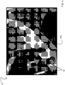
FIG. 4 is a perspective view of a mating surface of a gearbox housing of a rotary wing aircraft according to an embodiment of the invention; -
FIG. 5 is a cross-sectional view of a portion of a gearbox housing having an integrally formed structural deposit according to an embodiment of the invention; -
FIG. 6 is a method for rebuilding a portion of a surface of a gearbox housing; and -
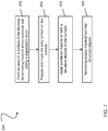
FIG. 7 is a method for preemptively forming a structural deposit in a surface of a gearbox housing according to an embodiment of the invention. - The detailed description explains embodiments of the invention, together with advantages and features, by way of example with reference to the drawings.
-
FIG. 1 schematically illustrates a rotary-wing aircraft 10 having amain rotor system 12. Theaircraft 10 includes an airframe 14 having an extending tail 16 which mounts atail rotor system 18, such as an anti-torque system, a translational thrust system, a pusher propeller, or a rotor propulsion system for example. Power is transferred from one or more engines E to a power transmission gearbox 20 (seeFIGS. 2a and 2b ), to drive themain rotor system 12 about a respective axis of rotation A. Although a particular rotary wing aircraft configuration is illustrated and described in the disclosed embodiment, other configurations and/or machines, such as a high speed compound rotary wing aircraft with supplemental translational thrust systems, a dual contra-rotating, coaxial rotor system aircraft, and a turboprop, tilt-rotor or tilt-wing aircraft for example, will also benefit from the present invention. - Referring now to
FIG. 2a , a schematic diagram of themain rotor system 12 and thetail rotor system 18 of theaircraft 10 ofFIG. 1 is provided in more detail. In the illustrated non-limiting embodiment, thepower transmission gearbox 20 is interposed between one or more engines E, themain rotor system 12 and thetail rotor system 18. Thegearbox 20 may be mechanically connected to and configured to operate both themain rotor system 12 and thetail rotor system 18. In another embodiment, shown inFIG. 2b , therotary wing aircraft 10 includes a firstpower transmission gearbox 20 mechanically coupled to and configured to operate themain rotor system 12. Similarly, the secondpower transmission gearbox 21 is mechanically connected to and configured to operate thetail rotor system 18. Each of thepower transmission gearboxes aircraft 10. - The
power transmission gearbox housing 22 configured to support the gear-train therein. In one embodiment, the housing includes either an aluminum or a magnesium material. The non-limiting embodiment of ahousing 22 illustrated inFIG. 3 generally includes a plurality offirst openings 24 configured to provide a plurality of passageways for a lubricant to various portions of thegearbox 20. Thehousing 22 may also include a plurality ofsecond openings 26 configured to at least partially support an input module attachment (not shown), such as the rotor shaft (not shown) of themain rotor system 12 or thetail rotor system 18 for example. In addition, thehousing 22 may include a plurality of mountingfeet 28 arranged about the periphery thereof near afirst end 23. Although aparticular gearbox housing 22 configuration is illustrated and described in the disclosed non-limiting embodiment, other configurations are within the scope of the invention. - The portions of the
housing 22 that are most susceptible to damage, as well as corrosion and pitting are generally thesurfaces 30 configured to contact or engage another component and/or a material distinguishable from the material of thehousing 22. Thesesurfaces 30 are theend mating surface 30a,flight control surfaces 30b, andbottom surfaces 30c. Theend mating surface 30a is located at thefirst end 23 of thehousing 22 and is configured to engage a portion of the airframe 14 or another component of theaircraft 10. As illustrated inFIG. 4 , at least onefastener 32 may extend generally perpendicularly from theend mating surface 30a, the at least onefastener 32 being configured to connect thefirst end 23 of thehousing 22 to another portion of theaircraft 10. Eachflight control surface 30b is configured to couple to a flight control or another component (not shown) of theaircraft 10. A plurality offlight control surfaces 30b may be disposed about the exterior of thehousing 22 and may be arranged at any angle relative to theend mating surface 30a. Similarly, the bottom surfaces 30c are the portion of the mountingfeet 28, such as the underside for example, configured to contact another component of theaircraft 10 or a portion of the airframe 14. - Referring now to
FIG. 5 , astructural deposit 40 configured to support a load applied to thehousing 22 is formed on at least a portion of asurface 30 of thegearbox housing 22 susceptible to corrosion and pitting. Thestructural deposit 40 may be formed from any suitable powdered material known in the art, such as aluminum or aluminum alloy for example. Thestructural deposit 40 is formed as a "preemptive repair" based on a determination of where corrosion and pitting is most likely to occur. - A
structural deposit 40 is formed by applying one or more layers of powdered material to anarea 42 of thesurface 30. When thestructural deposit 40 is applied "preemptively," eacharea 42 is created by removing material from thesurface 30 where corrosion and pitting are most likely to occur. The one ormore areas 42 formed in thesurface 30 are concave grooves. - The one or more layers of powdered material used to form the
structural deposit 40 are more substantial than a coating and are configured to share a load applied over thesurface 30. As a result, the strength of ahousing 22 having one or morestructural deposits 40 integrally formed with thesurfaces 30 where corrosion and pitting has/is likely to occur is near, substantially equal to, or in excess of the original strength of thehousing 22. Thestructural deposit 40 formed from one or more layers of powdered material may have a thickness in the range of about 0.254 mm to 50.8 mm (.010 inches and 2.00 inches). In one embodiment, thestructural deposit 40 has a thickness greater than or equal to 0.635 mm (.025 inches). depending on part geometry and other factors, to properly share the load applied to the component. - The layers of powdered material used to form the
structural deposit 40 are generally applied through a deposition process that provides sufficient energy to accelerate the particles to a high enough velocity such that the particles plastically deform and bond to thearea 42 upon impact. The particles of the powered material are accelerated through a converging/divergingnozzle 52 of aspray gun 50 to supersonic velocities using a pressurized or compressed gas, such as helium, nitrogen, other inert gases, or mixtures thereof. The deposition process does not metallurgically transform the particles from their solid state. Various techniques may be used to achieve this type of particle deposition, including but not limited to, cold spray deposition, kinetic metallization, electromagnetic particle acceleration, modified high velocity air fuel spraying, or high velocity impact fusion (HVIF) for example. - The layers of powered material may be applied to the original material of the
housing 22, or alternatively, may be applied to a previously formedstructural deposit 40. During deposition of the powdered material, thegearbox housing 22 may be held stationary or may be articulated or translated by any suitable means (not shown) known in the art. Alternatively, thenozzle 52 of thespray gun 50 may be held stationary or may be articulated or translated. In some instances, both thegearbox housing 22 and thenozzle 52 may be manipulated, either sequentially or simultaneously. - A method 100 (not according to the invention) for rebuilding a damaged or corroded portion of a
surface 30 of agearbox housing 22 is illustrated inFIG. 6 . Thesurface 30 may be any of thesurfaces block 102 by removing all of the localized damage or corrosion from a portion ofsurface 30 to form an area 42 (seeFIG. 5 ). The corrosion and pitting may be removed either mechanically or chemically, for example using grinding, machining, etching, or other applicable techniques. After the localized corrosion is removed, as shown inblock 104, thesurface 30 is prepared and masked as is known in the art. In one example, preparation and masking of thesurface 30 involves the use of an abrasive grit blast. An additional material may be used to eliminate any blast residue as a course of contamination prevention. Inblock 106, at least one layer of powdered material is applied to thearea 42 using a cold spray deposition process to create astructural deposit 40 integrally formed with the material of thehousing 22. Thestructural deposit 40 bonded to thearea 42 may extend beyond the original dimension of thesurface 30 of thegearbox housing 22. After formation of thestructural deposit 40, excess material is removed as necessary, as shown inblock 108. As a result, thestructural deposit 40 is generally flush with the remainder of thesurface 30 of thegearbox housing 22 and/or the dimension of thegearbox housing 22 including thestructural deposit 40 is substantially equal to the original dimension thereof. - A
method 200 of preemptively forming astructural deposit 40 in asurface 30 of ahousing 22 is illustrated inFIG. 7 . Thesurface 30 may be any of thesurfaces method 200 may begin inblock 202 by removing some material from thesurface 30 of anunused gearbox housing 22, at a position where localized corrosion and pitting is most likely to occur, to form anarea 42. Material may be removed from thesurface 30 either mechanically or chemically, for example using grinding, machining, etching, or other applicable techniques. In embodiments where astructural deposit 40 is being added to the existing surface of thehousing 22 without first removing any material, the step illustrated inblock 202 may be skipped. Inblock 204, the portion of thesurface 30 configured to receive thestructural deposit 40, such asarea 42 for example, is prepared and masked, as previously discussed. Inblock 206, at least one layer of powdered material is applied using a cold spray deposition process to form astructural deposit 40. Thestructural deposit 40 bonded to thesurface 30 may extend beyond a desired dimension, such as the original dimension of thesurface 30 of thegearbox housing 22 for example. In such instances, excess material is removed after formation of thestructural deposit 40, as shown inblock 208. Theexcess material 40 may be removed so that thestructural deposit 40 is generally flush with the remainder of thesurface 30 of thegearbox housing 22 so that the dimension of thegearbox housing 22 including thestructural deposit 40 is substantially equal to the original dimension thereof. - Formation of one or more
structural deposits 40 in the surfaces of agearbox housing 22 can reduce and/or prevent corrosion and pitting, thereby improving the life of thehousing 22. In addition, because thestructural deposits 40 are configured to share the load applied to thesurface 30, inclusion of one or morestructural deposits 40 does not affect or minimally decreases the structural integrity of thehousing 22.
Claims (3)
- A method of preemptively forming a structural deposit (40) on a surface of an unused gearbox housing (22), the surface (30) configured to contact a component, the method comprising the steps of:identifying a portion of the surface (30) of the gearbox housing (22) where corrosion and pitting are expected to occur;removing material from the portion of the surface (30) of the gearbox housing (22) as a concave groove;preparing and masking the portion of the surface (30);creating a structural deposit (40) on the identified portion of the surface (30), wherein the structural deposit (40) includes one or more layers of powdered material applied through a cold spray deposition process, the structural deposit (40) being integrally formed with gearbox housing (22) and configured to carry a load applied to the gearbox housing (22); andremoving any excess material from the structural deposit (40);wherein the surface (30) is one of a mating surface (30a), a flight control surface (30b), and a mounting foot portion (30c) configured to contact the component, and the component is one of a fastener, a flight control component, and an airframe, wherein the gearbox housing (22) is of an aircraft (10).
- The method according to claim 1, wherein the gearbox housing (22) is of a rotary wing aircraft (10).
- The method according to claim 1, wherein the powdered material includes aluminum.
Priority Applications (1)
| Application Number | Priority Date | Filing Date | Title |
|---|---|---|---|
| PL14879970T PL3066232T3 (en) | 2013-11-06 | 2014-11-06 | Damage mitigation for gearbox |
Applications Claiming Priority (2)
| Application Number | Priority Date | Filing Date | Title |
|---|---|---|---|
| US14/073,162 US9599210B2 (en) | 2013-11-06 | 2013-11-06 | Damage mitigation for gearbox |
| PCT/US2014/064259 WO2015112228A2 (en) | 2013-11-06 | 2014-11-06 | Damage mitigation for gearbox |
Publications (3)
| Publication Number | Publication Date |
|---|---|
| EP3066232A2 EP3066232A2 (en) | 2016-09-14 |
| EP3066232A4 EP3066232A4 (en) | 2017-06-07 |
| EP3066232B1 true EP3066232B1 (en) | 2020-05-06 |
Family
ID=53006007
Family Applications (1)
| Application Number | Title | Priority Date | Filing Date |
|---|---|---|---|
| EP14879970.3A Active EP3066232B1 (en) | 2013-11-06 | 2014-11-06 | Damage mitigation for gearbox |
Country Status (5)
| Country | Link |
|---|---|
| US (2) | US9599210B2 (en) |
| EP (1) | EP3066232B1 (en) |
| JP (1) | JP6527144B2 (en) |
| PL (1) | PL3066232T3 (en) |
| WO (1) | WO2015112228A2 (en) |
Cited By (3)
| Publication number | Priority date | Publication date | Assignee | Title |
|---|---|---|---|---|
| US11662300B2 (en) | 2019-09-19 | 2023-05-30 | Westinghouse Electric Company Llc | Apparatus for performing in-situ adhesion test of cold spray deposits and method of employing |
| US11898986B2 (en) | 2012-10-10 | 2024-02-13 | Westinghouse Electric Company Llc | Systems and methods for steam generator tube analysis for detection of tube degradation |
| US11935662B2 (en) | 2019-07-02 | 2024-03-19 | Westinghouse Electric Company Llc | Elongate SiC fuel elements |
Families Citing this family (5)
| Publication number | Priority date | Publication date | Assignee | Title |
|---|---|---|---|---|
| US10077499B2 (en) | 2013-11-06 | 2018-09-18 | Sikorsky Aircraft Corporation | Corrosion mitigation for gearbox |
| US9599210B2 (en) | 2013-11-06 | 2017-03-21 | Sikorsky Aircraft Corporation | Damage mitigation for gearbox |
| US20170333934A1 (en) * | 2014-11-11 | 2017-11-23 | Sikorsky Aircraft Corporation | Masking plug for cold spray repair at counterbore hole |
| AU2016202759B2 (en) * | 2015-05-21 | 2021-04-29 | Rosebank Engineering Pty Ltd | Methods for restoring an aircraft frame element |
| US20180133851A1 (en) * | 2016-11-17 | 2018-05-17 | Sikorsky Aircraft Corporation | Method of reversing surface stress on a coated component |
Family Cites Families (32)
| Publication number | Priority date | Publication date | Assignee | Title |
|---|---|---|---|---|
| US2495988A (en) | 1943-07-14 | 1950-01-31 | Borg Warner | Transmission gearing |
| US3711310A (en) * | 1971-07-26 | 1973-01-16 | United Aircraft Corp | Repair process for aluminum and magnesium articles |
| US4028787A (en) | 1975-09-15 | 1977-06-14 | Cretella Salvatore | Refurbished turbine vanes and method of refurbishment thereof |
| DE69016433T2 (en) * | 1990-05-19 | 1995-07-20 | Papyrin Anatolij Nikiforovic | COATING METHOD AND DEVICE. |
| KR100204029B1 (en) | 1996-06-19 | 1999-06-15 | 이계철 | How to Assign a Connection Identifier in an Asynchronous Delivery Mode Switching System |
| US6491208B2 (en) * | 2000-12-05 | 2002-12-10 | Siemens Westinghouse Power Corporation | Cold spray repair process |
| DK1578540T3 (en) | 2002-09-25 | 2011-04-18 | Alcoa Inc | Coated Vehicle Wheel and Procedure |
| US7648593B2 (en) | 2003-01-15 | 2010-01-19 | United Technologies Corporation | Aluminum based alloy |
| US7188416B1 (en) * | 2003-02-05 | 2007-03-13 | Brunswick Corporation | Restoration process for porosity defects in high pressure die cast engine blocks |
| US8220124B1 (en) * | 2003-02-05 | 2012-07-17 | Brunswick Corporation | Restoration process for porosity defects in metal cast products |
| JP4000075B2 (en) * | 2003-02-27 | 2007-10-31 | 株式会社東芝 | Rotor repair method |
| US6905728B1 (en) | 2004-03-22 | 2005-06-14 | Honeywell International, Inc. | Cold gas-dynamic spray repair on gas turbine engine components |
| US20060093736A1 (en) | 2004-10-29 | 2006-05-04 | Derek Raybould | Aluminum articles with wear-resistant coatings and methods for applying the coatings onto the articles |
| US20060090593A1 (en) | 2004-11-03 | 2006-05-04 | Junhai Liu | Cold spray formation of thin metal coatings |
| US20060134320A1 (en) * | 2004-12-21 | 2006-06-22 | United Technologies Corporation | Structural repair using cold sprayed aluminum materials |
| US7455881B2 (en) | 2005-04-25 | 2008-11-25 | Honeywell International Inc. | Methods for coating a magnesium component |
| US7875132B2 (en) | 2005-05-31 | 2011-01-25 | United Technologies Corporation | High temperature aluminum alloys |
| US7402277B2 (en) | 2006-02-07 | 2008-07-22 | Exxonmobil Research And Engineering Company | Method of forming metal foams by cold spray technique |
| EP1829988A1 (en) * | 2006-03-02 | 2007-09-05 | Praxair Surface Technologies GmbH | Method of repairing and refurbishing an aluminum component under dynamic loading for airfoil equipments |
| JP2008274352A (en) | 2007-04-27 | 2008-11-13 | Ihi Corp | Sealing complement method, metal member repair method, and metal defect repair device |
| US8597724B2 (en) * | 2007-07-06 | 2013-12-03 | United Technologies Corporation | Corrosion protective coating through cold spray |
| EP2238362B1 (en) | 2008-01-07 | 2015-03-11 | Bell Helicopter Textron Inc. | Rotorcraft with housing assembly having improved bearing liner |
| US20090249603A1 (en) * | 2008-04-08 | 2009-10-08 | Chris Vargas | Cold deposition repair of casting porosity |
| US20100143700A1 (en) | 2008-12-08 | 2010-06-10 | Victor K Champagne | Cold spray impact deposition system and coating process |
| US8231936B2 (en) | 2008-12-10 | 2012-07-31 | GM Global Technology Operations LLC | Methods of reducing corrosion between magnesium and another metal |
| US20100155251A1 (en) | 2008-12-23 | 2010-06-24 | United Technologies Corporation | Hard anodize of cold spray aluminum layer |
| US8601663B2 (en) | 2012-02-13 | 2013-12-10 | Honeywell International Inc. | Methods for structural repair of components having damaged internally threaded openings and components repaired using such methods |
| US10093434B2 (en) * | 2012-03-29 | 2018-10-09 | Rosebank Engineering Pty Ltd | Methods for treating aircraft structures |
| US10099322B2 (en) * | 2012-10-29 | 2018-10-16 | South Dakota Board Of Regents | Methods for cold spray repair |
| US9394063B2 (en) * | 2013-03-15 | 2016-07-19 | Bell Helicopter Textron Inc. | Methods utilizing cold spray techniques for repairing and protecting rotary components of aviation propulsion systems |
| US10077499B2 (en) | 2013-11-06 | 2018-09-18 | Sikorsky Aircraft Corporation | Corrosion mitigation for gearbox |
| US9599210B2 (en) | 2013-11-06 | 2017-03-21 | Sikorsky Aircraft Corporation | Damage mitigation for gearbox |
-
2013
- 2013-11-06 US US14/073,162 patent/US9599210B2/en active Active
-
2014
- 2014-11-06 JP JP2016528222A patent/JP6527144B2/en active Active
- 2014-11-06 EP EP14879970.3A patent/EP3066232B1/en active Active
- 2014-11-06 WO PCT/US2014/064259 patent/WO2015112228A2/en not_active Ceased
- 2014-11-06 PL PL14879970T patent/PL3066232T3/en unknown
-
2017
- 2017-02-08 US US15/427,537 patent/US10677340B2/en active Active
Non-Patent Citations (1)
| Title |
|---|
| None * |
Cited By (3)
| Publication number | Priority date | Publication date | Assignee | Title |
|---|---|---|---|---|
| US11898986B2 (en) | 2012-10-10 | 2024-02-13 | Westinghouse Electric Company Llc | Systems and methods for steam generator tube analysis for detection of tube degradation |
| US11935662B2 (en) | 2019-07-02 | 2024-03-19 | Westinghouse Electric Company Llc | Elongate SiC fuel elements |
| US11662300B2 (en) | 2019-09-19 | 2023-05-30 | Westinghouse Electric Company Llc | Apparatus for performing in-situ adhesion test of cold spray deposits and method of employing |
Also Published As
| Publication number | Publication date |
|---|---|
| US9599210B2 (en) | 2017-03-21 |
| EP3066232A2 (en) | 2016-09-14 |
| US20170299040A1 (en) | 2017-10-19 |
| US10677340B2 (en) | 2020-06-09 |
| WO2015112228A2 (en) | 2015-07-30 |
| US20150122079A1 (en) | 2015-05-07 |
| EP3066232A4 (en) | 2017-06-07 |
| JP6527144B2 (en) | 2019-06-05 |
| WO2015112228A3 (en) | 2015-10-29 |
| PL3066232T3 (en) | 2020-10-19 |
| JP2016538498A (en) | 2016-12-08 |
Similar Documents
| Publication | Publication Date | Title |
|---|---|---|
| US10677340B2 (en) | Damage mitigation for gearbox | |
| EP3066233B1 (en) | Corrosion mitigation for gearbox | |
| US8533949B2 (en) | Methods of manufacture for components with cooling channels | |
| CN102560481B (en) | Two-layer structure coating is used to manufacture the method for component | |
| US20170333934A1 (en) | Masking plug for cold spray repair at counterbore hole | |
| US8910379B2 (en) | Wireless component and methods of fabricating a coated component using multiple types of fillers | |
| US20120114868A1 (en) | Method of fabricating a component using a fugitive coating | |
| US20060222776A1 (en) | Environment-resistant platinum aluminide coatings, and methods of applying the same onto turbine components | |
| US20140301861A1 (en) | Airfoil having an erosion-resistant coating thereon | |
| EP2204473A2 (en) | Hard anodize of cold spray aluminum layer | |
| EP1895021A1 (en) | Erosion-protective coatings on polymer-matrix composites and components incorporating such coated composites | |
| US20120295061A1 (en) | Components with precision surface channels and hybrid machining method | |
| KR20090007306A (en) | Process for the repair and restoration of dynamically stressed components comprising aluminium alloys for aircraft applications | |
| WO2008140588A1 (en) | Method for producing an environmentally-resistant thermal barrier coating system on a component | |
| US20150111058A1 (en) | Method of coating a composite material and a coated edge of a composite structure | |
| Harvey et al. | The potential of the cold spray process for the repair and manufacture of aluminium alloy parts | |
| JP2020097218A (en) | Laminate composite structural components and methods for the same | |
| Archambault | Lay-up Moulding of a Carbon Fiber Reinforced Polymer Composite on a Cold Sprayed Metallic Layer | |
| Cormier | Repair of Conductive Layer on Carbon Fibre Reinforced Polymer Composite with Cold Gas Dynamic Spray |
Legal Events
| Date | Code | Title | Description |
|---|---|---|---|
| PUAI | Public reference made under article 153(3) epc to a published international application that has entered the european phase |
Free format text: ORIGINAL CODE: 0009012 |
|
| 17P | Request for examination filed |
Effective date: 20160602 |
|
| AK | Designated contracting states |
Kind code of ref document: A2 Designated state(s): AL AT BE BG CH CY CZ DE DK EE ES FI FR GB GR HR HU IE IS IT LI LT LU LV MC MK MT NL NO PL PT RO RS SE SI SK SM TR |
|
| AX | Request for extension of the european patent |
Extension state: BA ME |
|
| DAX | Request for extension of the european patent (deleted) | ||
| A4 | Supplementary search report drawn up and despatched |
Effective date: 20170509 |
|
| RIC1 | Information provided on ipc code assigned before grant |
Ipc: C23C 24/04 20060101AFI20170502BHEP Ipc: F16H 57/032 20120101ALI20170502BHEP |
|
| STAA | Information on the status of an ep patent application or granted ep patent |
Free format text: STATUS: EXAMINATION IS IN PROGRESS |
|
| 17Q | First examination report despatched |
Effective date: 20180131 |
|
| GRAP | Despatch of communication of intention to grant a patent |
Free format text: ORIGINAL CODE: EPIDOSNIGR1 |
|
| STAA | Information on the status of an ep patent application or granted ep patent |
Free format text: STATUS: GRANT OF PATENT IS INTENDED |
|
| INTG | Intention to grant announced |
Effective date: 20191121 |
|
| GRAS | Grant fee paid |
Free format text: ORIGINAL CODE: EPIDOSNIGR3 |
|
| GRAA | (expected) grant |
Free format text: ORIGINAL CODE: 0009210 |
|
| STAA | Information on the status of an ep patent application or granted ep patent |
Free format text: STATUS: THE PATENT HAS BEEN GRANTED |
|
| AK | Designated contracting states |
Kind code of ref document: B1 Designated state(s): AL AT BE BG CH CY CZ DE DK EE ES FI FR GB GR HR HU IE IS IT LI LT LU LV MC MK MT NL NO PL PT RO RS SE SI SK SM TR |
|
| REG | Reference to a national code |
Ref country code: GB Ref legal event code: FG4D |
|
| REG | Reference to a national code |
Ref country code: CH Ref legal event code: EP Ref country code: AT Ref legal event code: REF Ref document number: 1266855 Country of ref document: AT Kind code of ref document: T Effective date: 20200515 |
|
| REG | Reference to a national code |
Ref country code: IE Ref legal event code: FG4D |
|
| REG | Reference to a national code |
Ref country code: DE Ref legal event code: R096 Ref document number: 602014065278 Country of ref document: DE |
|
| REG | Reference to a national code |
Ref country code: LT Ref legal event code: MG4D |
|
| REG | Reference to a national code |
Ref country code: NL Ref legal event code: MP Effective date: 20200506 |
|
| PG25 | Lapsed in a contracting state [announced via postgrant information from national office to epo] |
Ref country code: PT Free format text: LAPSE BECAUSE OF FAILURE TO SUBMIT A TRANSLATION OF THE DESCRIPTION OR TO PAY THE FEE WITHIN THE PRESCRIBED TIME-LIMIT Effective date: 20200907 Ref country code: LT Free format text: LAPSE BECAUSE OF FAILURE TO SUBMIT A TRANSLATION OF THE DESCRIPTION OR TO PAY THE FEE WITHIN THE PRESCRIBED TIME-LIMIT Effective date: 20200506 Ref country code: FI Free format text: LAPSE BECAUSE OF FAILURE TO SUBMIT A TRANSLATION OF THE DESCRIPTION OR TO PAY THE FEE WITHIN THE PRESCRIBED TIME-LIMIT Effective date: 20200506 Ref country code: NO Free format text: LAPSE BECAUSE OF FAILURE TO SUBMIT A TRANSLATION OF THE DESCRIPTION OR TO PAY THE FEE WITHIN THE PRESCRIBED TIME-LIMIT Effective date: 20200806 Ref country code: IS Free format text: LAPSE BECAUSE OF FAILURE TO SUBMIT A TRANSLATION OF THE DESCRIPTION OR TO PAY THE FEE WITHIN THE PRESCRIBED TIME-LIMIT Effective date: 20200906 Ref country code: SE Free format text: LAPSE BECAUSE OF FAILURE TO SUBMIT A TRANSLATION OF THE DESCRIPTION OR TO PAY THE FEE WITHIN THE PRESCRIBED TIME-LIMIT Effective date: 20200506 Ref country code: GR Free format text: LAPSE BECAUSE OF FAILURE TO SUBMIT A TRANSLATION OF THE DESCRIPTION OR TO PAY THE FEE WITHIN THE PRESCRIBED TIME-LIMIT Effective date: 20200807 |
|
| PG25 | Lapsed in a contracting state [announced via postgrant information from national office to epo] |
Ref country code: BG Free format text: LAPSE BECAUSE OF FAILURE TO SUBMIT A TRANSLATION OF THE DESCRIPTION OR TO PAY THE FEE WITHIN THE PRESCRIBED TIME-LIMIT Effective date: 20200806 Ref country code: RS Free format text: LAPSE BECAUSE OF FAILURE TO SUBMIT A TRANSLATION OF THE DESCRIPTION OR TO PAY THE FEE WITHIN THE PRESCRIBED TIME-LIMIT Effective date: 20200506 Ref country code: LV Free format text: LAPSE BECAUSE OF FAILURE TO SUBMIT A TRANSLATION OF THE DESCRIPTION OR TO PAY THE FEE WITHIN THE PRESCRIBED TIME-LIMIT Effective date: 20200506 Ref country code: HR Free format text: LAPSE BECAUSE OF FAILURE TO SUBMIT A TRANSLATION OF THE DESCRIPTION OR TO PAY THE FEE WITHIN THE PRESCRIBED TIME-LIMIT Effective date: 20200506 |
|
| REG | Reference to a national code |
Ref country code: AT Ref legal event code: MK05 Ref document number: 1266855 Country of ref document: AT Kind code of ref document: T Effective date: 20200506 |
|
| PG25 | Lapsed in a contracting state [announced via postgrant information from national office to epo] |
Ref country code: AL Free format text: LAPSE BECAUSE OF FAILURE TO SUBMIT A TRANSLATION OF THE DESCRIPTION OR TO PAY THE FEE WITHIN THE PRESCRIBED TIME-LIMIT Effective date: 20200506 Ref country code: NL Free format text: LAPSE BECAUSE OF FAILURE TO SUBMIT A TRANSLATION OF THE DESCRIPTION OR TO PAY THE FEE WITHIN THE PRESCRIBED TIME-LIMIT Effective date: 20200506 |
|
| PG25 | Lapsed in a contracting state [announced via postgrant information from national office to epo] |
Ref country code: EE Free format text: LAPSE BECAUSE OF FAILURE TO SUBMIT A TRANSLATION OF THE DESCRIPTION OR TO PAY THE FEE WITHIN THE PRESCRIBED TIME-LIMIT Effective date: 20200506 Ref country code: SM Free format text: LAPSE BECAUSE OF FAILURE TO SUBMIT A TRANSLATION OF THE DESCRIPTION OR TO PAY THE FEE WITHIN THE PRESCRIBED TIME-LIMIT Effective date: 20200506 Ref country code: DK Free format text: LAPSE BECAUSE OF FAILURE TO SUBMIT A TRANSLATION OF THE DESCRIPTION OR TO PAY THE FEE WITHIN THE PRESCRIBED TIME-LIMIT Effective date: 20200506 Ref country code: IT Free format text: LAPSE BECAUSE OF FAILURE TO SUBMIT A TRANSLATION OF THE DESCRIPTION OR TO PAY THE FEE WITHIN THE PRESCRIBED TIME-LIMIT Effective date: 20200506 Ref country code: RO Free format text: LAPSE BECAUSE OF FAILURE TO SUBMIT A TRANSLATION OF THE DESCRIPTION OR TO PAY THE FEE WITHIN THE PRESCRIBED TIME-LIMIT Effective date: 20200506 Ref country code: AT Free format text: LAPSE BECAUSE OF FAILURE TO SUBMIT A TRANSLATION OF THE DESCRIPTION OR TO PAY THE FEE WITHIN THE PRESCRIBED TIME-LIMIT Effective date: 20200506 Ref country code: CZ Free format text: LAPSE BECAUSE OF FAILURE TO SUBMIT A TRANSLATION OF THE DESCRIPTION OR TO PAY THE FEE WITHIN THE PRESCRIBED TIME-LIMIT Effective date: 20200506 Ref country code: ES Free format text: LAPSE BECAUSE OF FAILURE TO SUBMIT A TRANSLATION OF THE DESCRIPTION OR TO PAY THE FEE WITHIN THE PRESCRIBED TIME-LIMIT Effective date: 20200506 |
|
| REG | Reference to a national code |
Ref country code: DE Ref legal event code: R097 Ref document number: 602014065278 Country of ref document: DE |
|
| PG25 | Lapsed in a contracting state [announced via postgrant information from national office to epo] |
Ref country code: SK Free format text: LAPSE BECAUSE OF FAILURE TO SUBMIT A TRANSLATION OF THE DESCRIPTION OR TO PAY THE FEE WITHIN THE PRESCRIBED TIME-LIMIT Effective date: 20200506 |
|
| PLBE | No opposition filed within time limit |
Free format text: ORIGINAL CODE: 0009261 |
|
| STAA | Information on the status of an ep patent application or granted ep patent |
Free format text: STATUS: NO OPPOSITION FILED WITHIN TIME LIMIT |
|
| 26N | No opposition filed |
Effective date: 20210209 |
|
| PG25 | Lapsed in a contracting state [announced via postgrant information from national office to epo] |
Ref country code: SI Free format text: LAPSE BECAUSE OF FAILURE TO SUBMIT A TRANSLATION OF THE DESCRIPTION OR TO PAY THE FEE WITHIN THE PRESCRIBED TIME-LIMIT Effective date: 20200506 |
|
| PG25 | Lapsed in a contracting state [announced via postgrant information from national office to epo] |
Ref country code: MC Free format text: LAPSE BECAUSE OF FAILURE TO SUBMIT A TRANSLATION OF THE DESCRIPTION OR TO PAY THE FEE WITHIN THE PRESCRIBED TIME-LIMIT Effective date: 20200506 |
|
| REG | Reference to a national code |
Ref country code: CH Ref legal event code: PL |
|
| PG25 | Lapsed in a contracting state [announced via postgrant information from national office to epo] |
Ref country code: LU Free format text: LAPSE BECAUSE OF NON-PAYMENT OF DUE FEES Effective date: 20201106 |
|
| REG | Reference to a national code |
Ref country code: BE Ref legal event code: MM Effective date: 20201130 |
|
| PG25 | Lapsed in a contracting state [announced via postgrant information from national office to epo] |
Ref country code: LI Free format text: LAPSE BECAUSE OF NON-PAYMENT OF DUE FEES Effective date: 20201130 Ref country code: CH Free format text: LAPSE BECAUSE OF NON-PAYMENT OF DUE FEES Effective date: 20201130 |
|
| PG25 | Lapsed in a contracting state [announced via postgrant information from national office to epo] |
Ref country code: IE Free format text: LAPSE BECAUSE OF NON-PAYMENT OF DUE FEES Effective date: 20201106 |
|
| PG25 | Lapsed in a contracting state [announced via postgrant information from national office to epo] |
Ref country code: TR Free format text: LAPSE BECAUSE OF FAILURE TO SUBMIT A TRANSLATION OF THE DESCRIPTION OR TO PAY THE FEE WITHIN THE PRESCRIBED TIME-LIMIT Effective date: 20200506 Ref country code: MT Free format text: LAPSE BECAUSE OF FAILURE TO SUBMIT A TRANSLATION OF THE DESCRIPTION OR TO PAY THE FEE WITHIN THE PRESCRIBED TIME-LIMIT Effective date: 20200506 Ref country code: CY Free format text: LAPSE BECAUSE OF FAILURE TO SUBMIT A TRANSLATION OF THE DESCRIPTION OR TO PAY THE FEE WITHIN THE PRESCRIBED TIME-LIMIT Effective date: 20200506 |
|
| PG25 | Lapsed in a contracting state [announced via postgrant information from national office to epo] |
Ref country code: MK Free format text: LAPSE BECAUSE OF FAILURE TO SUBMIT A TRANSLATION OF THE DESCRIPTION OR TO PAY THE FEE WITHIN THE PRESCRIBED TIME-LIMIT Effective date: 20200506 |
|
| PG25 | Lapsed in a contracting state [announced via postgrant information from national office to epo] |
Ref country code: BE Free format text: LAPSE BECAUSE OF NON-PAYMENT OF DUE FEES Effective date: 20201130 |
|
| P01 | Opt-out of the competence of the unified patent court (upc) registered |
Effective date: 20230520 |
|
| PGFP | Annual fee paid to national office [announced via postgrant information from national office to epo] |
Ref country code: DE Payment date: 20251128 Year of fee payment: 12 |
|
| PGFP | Annual fee paid to national office [announced via postgrant information from national office to epo] |
Ref country code: GB Payment date: 20251127 Year of fee payment: 12 |
|
| PGFP | Annual fee paid to national office [announced via postgrant information from national office to epo] |
Ref country code: FR Payment date: 20251125 Year of fee payment: 12 |
|
| PGFP | Annual fee paid to national office [announced via postgrant information from national office to epo] |
Ref country code: PL Payment date: 20251021 Year of fee payment: 12 |