EP3065963B1 - Liquid vapor separator drain valve - Google Patents
Liquid vapor separator drain valve Download PDFInfo
- Publication number
- EP3065963B1 EP3065963B1 EP14802555.4A EP14802555A EP3065963B1 EP 3065963 B1 EP3065963 B1 EP 3065963B1 EP 14802555 A EP14802555 A EP 14802555A EP 3065963 B1 EP3065963 B1 EP 3065963B1
- Authority
- EP
- European Patent Office
- Prior art keywords
- housing
- port
- valve
- lvsdv
- vent
- Prior art date
- Legal status (The legal status is an assumption and is not a legal conclusion. Google has not performed a legal analysis and makes no representation as to the accuracy of the status listed.)
- Active
Links
Images




Classifications
-
- B—PERFORMING OPERATIONS; TRANSPORTING
- B60—VEHICLES IN GENERAL
- B60K—ARRANGEMENT OR MOUNTING OF PROPULSION UNITS OR OF TRANSMISSIONS IN VEHICLES; ARRANGEMENT OR MOUNTING OF PLURAL DIVERSE PRIME-MOVERS IN VEHICLES; AUXILIARY DRIVES FOR VEHICLES; INSTRUMENTATION OR DASHBOARDS FOR VEHICLES; ARRANGEMENTS IN CONNECTION WITH COOLING, AIR INTAKE, GAS EXHAUST OR FUEL SUPPLY OF PROPULSION UNITS IN VEHICLES
- B60K15/00—Arrangement in connection with fuel supply of combustion engines or other fuel consuming energy converters, e.g. fuel cells; Mounting or construction of fuel tanks
- B60K15/03—Fuel tanks
- B60K15/035—Fuel tanks characterised by venting means
- B60K15/03519—Valve arrangements in the vent line
-
- B—PERFORMING OPERATIONS; TRANSPORTING
- B60—VEHICLES IN GENERAL
- B60K—ARRANGEMENT OR MOUNTING OF PROPULSION UNITS OR OF TRANSMISSIONS IN VEHICLES; ARRANGEMENT OR MOUNTING OF PLURAL DIVERSE PRIME-MOVERS IN VEHICLES; AUXILIARY DRIVES FOR VEHICLES; INSTRUMENTATION OR DASHBOARDS FOR VEHICLES; ARRANGEMENTS IN CONNECTION WITH COOLING, AIR INTAKE, GAS EXHAUST OR FUEL SUPPLY OF PROPULSION UNITS IN VEHICLES
- B60K15/00—Arrangement in connection with fuel supply of combustion engines or other fuel consuming energy converters, e.g. fuel cells; Mounting or construction of fuel tanks
- B60K15/03—Fuel tanks
- B60K15/035—Fuel tanks characterised by venting means
-
- B—PERFORMING OPERATIONS; TRANSPORTING
- B60—VEHICLES IN GENERAL
- B60K—ARRANGEMENT OR MOUNTING OF PROPULSION UNITS OR OF TRANSMISSIONS IN VEHICLES; ARRANGEMENT OR MOUNTING OF PLURAL DIVERSE PRIME-MOVERS IN VEHICLES; AUXILIARY DRIVES FOR VEHICLES; INSTRUMENTATION OR DASHBOARDS FOR VEHICLES; ARRANGEMENTS IN CONNECTION WITH COOLING, AIR INTAKE, GAS EXHAUST OR FUEL SUPPLY OF PROPULSION UNITS IN VEHICLES
- B60K15/00—Arrangement in connection with fuel supply of combustion engines or other fuel consuming energy converters, e.g. fuel cells; Mounting or construction of fuel tanks
- B60K15/03—Fuel tanks
- B60K15/035—Fuel tanks characterised by venting means
- B60K15/03504—Fuel tanks characterised by venting means adapted to avoid loss of fuel or fuel vapour, e.g. with vapour recovery systems
-
- F—MECHANICAL ENGINEERING; LIGHTING; HEATING; WEAPONS; BLASTING
- F02—COMBUSTION ENGINES; HOT-GAS OR COMBUSTION-PRODUCT ENGINE PLANTS
- F02M—SUPPLYING COMBUSTION ENGINES IN GENERAL WITH COMBUSTIBLE MIXTURES OR CONSTITUENTS THEREOF
- F02M25/00—Engine-pertinent apparatus for adding non-fuel substances or small quantities of secondary fuel to combustion-air, main fuel or fuel-air mixture
- F02M25/08—Engine-pertinent apparatus for adding non-fuel substances or small quantities of secondary fuel to combustion-air, main fuel or fuel-air mixture adding fuel vapours drawn from engine fuel reservoir
- F02M25/0872—Details of the fuel vapour pipes or conduits
-
- F—MECHANICAL ENGINEERING; LIGHTING; HEATING; WEAPONS; BLASTING
- F16—ENGINEERING ELEMENTS AND UNITS; GENERAL MEASURES FOR PRODUCING AND MAINTAINING EFFECTIVE FUNCTIONING OF MACHINES OR INSTALLATIONS; THERMAL INSULATION IN GENERAL
- F16K—VALVES; TAPS; COCKS; ACTUATING-FLOATS; DEVICES FOR VENTING OR AERATING
- F16K24/00—Devices, e.g. valves, for venting or aerating enclosures
- F16K24/04—Devices, e.g. valves, for venting or aerating enclosures for venting only
- F16K24/042—Devices, e.g. valves, for venting or aerating enclosures for venting only actuated by a float
-
- B—PERFORMING OPERATIONS; TRANSPORTING
- B60—VEHICLES IN GENERAL
- B60K—ARRANGEMENT OR MOUNTING OF PROPULSION UNITS OR OF TRANSMISSIONS IN VEHICLES; ARRANGEMENT OR MOUNTING OF PLURAL DIVERSE PRIME-MOVERS IN VEHICLES; AUXILIARY DRIVES FOR VEHICLES; INSTRUMENTATION OR DASHBOARDS FOR VEHICLES; ARRANGEMENTS IN CONNECTION WITH COOLING, AIR INTAKE, GAS EXHAUST OR FUEL SUPPLY OF PROPULSION UNITS IN VEHICLES
- B60K15/00—Arrangement in connection with fuel supply of combustion engines or other fuel consuming energy converters, e.g. fuel cells; Mounting or construction of fuel tanks
- B60K15/03—Fuel tanks
- B60K2015/03256—Fuel tanks characterised by special valves, the mounting thereof
- B60K2015/03289—Float valves; Floats therefor
-
- B—PERFORMING OPERATIONS; TRANSPORTING
- B60—VEHICLES IN GENERAL
- B60K—ARRANGEMENT OR MOUNTING OF PROPULSION UNITS OR OF TRANSMISSIONS IN VEHICLES; ARRANGEMENT OR MOUNTING OF PLURAL DIVERSE PRIME-MOVERS IN VEHICLES; AUXILIARY DRIVES FOR VEHICLES; INSTRUMENTATION OR DASHBOARDS FOR VEHICLES; ARRANGEMENTS IN CONNECTION WITH COOLING, AIR INTAKE, GAS EXHAUST OR FUEL SUPPLY OF PROPULSION UNITS IN VEHICLES
- B60K15/00—Arrangement in connection with fuel supply of combustion engines or other fuel consuming energy converters, e.g. fuel cells; Mounting or construction of fuel tanks
- B60K15/03—Fuel tanks
- B60K15/035—Fuel tanks characterised by venting means
- B60K15/03504—Fuel tanks characterised by venting means adapted to avoid loss of fuel or fuel vapour, e.g. with vapour recovery systems
- B60K2015/03514—Fuel tanks characterised by venting means adapted to avoid loss of fuel or fuel vapour, e.g. with vapour recovery systems with vapor recovery means
-
- F—MECHANICAL ENGINEERING; LIGHTING; HEATING; WEAPONS; BLASTING
- F02—COMBUSTION ENGINES; HOT-GAS OR COMBUSTION-PRODUCT ENGINE PLANTS
- F02M—SUPPLYING COMBUSTION ENGINES IN GENERAL WITH COMBUSTIBLE MIXTURES OR CONSTITUENTS THEREOF
- F02M25/00—Engine-pertinent apparatus for adding non-fuel substances or small quantities of secondary fuel to combustion-air, main fuel or fuel-air mixture
- F02M25/08—Engine-pertinent apparatus for adding non-fuel substances or small quantities of secondary fuel to combustion-air, main fuel or fuel-air mixture adding fuel vapours drawn from engine fuel reservoir
- F02M2025/0863—Engine-pertinent apparatus for adding non-fuel substances or small quantities of secondary fuel to combustion-air, main fuel or fuel-air mixture adding fuel vapours drawn from engine fuel reservoir with means dealing with condensed fuel or water, e.g. having a liquid trap
-
- Y—GENERAL TAGGING OF NEW TECHNOLOGICAL DEVELOPMENTS; GENERAL TAGGING OF CROSS-SECTIONAL TECHNOLOGIES SPANNING OVER SEVERAL SECTIONS OF THE IPC; TECHNICAL SUBJECTS COVERED BY FORMER USPC CROSS-REFERENCE ART COLLECTIONS [XRACs] AND DIGESTS
- Y10—TECHNICAL SUBJECTS COVERED BY FORMER USPC
- Y10T—TECHNICAL SUBJECTS COVERED BY FORMER US CLASSIFICATION
- Y10T137/00—Fluid handling
- Y10T137/2931—Diverse fluid containing pressure systems
- Y10T137/3003—Fluid separating traps or vents
- Y10T137/3084—Discriminating outlet for gas
-
- Y—GENERAL TAGGING OF NEW TECHNOLOGICAL DEVELOPMENTS; GENERAL TAGGING OF CROSS-SECTIONAL TECHNOLOGIES SPANNING OVER SEVERAL SECTIONS OF THE IPC; TECHNICAL SUBJECTS COVERED BY FORMER USPC CROSS-REFERENCE ART COLLECTIONS [XRACs] AND DIGESTS
- Y10—TECHNICAL SUBJECTS COVERED BY FORMER USPC
- Y10T—TECHNICAL SUBJECTS COVERED BY FORMER US CLASSIFICATION
- Y10T137/00—Fluid handling
- Y10T137/2931—Diverse fluid containing pressure systems
- Y10T137/3003—Fluid separating traps or vents
- Y10T137/3084—Discriminating outlet for gas
- Y10T137/309—Fluid sensing valve
- Y10T137/3099—Float responsive
-
- Y—GENERAL TAGGING OF NEW TECHNOLOGICAL DEVELOPMENTS; GENERAL TAGGING OF CROSS-SECTIONAL TECHNOLOGIES SPANNING OVER SEVERAL SECTIONS OF THE IPC; TECHNICAL SUBJECTS COVERED BY FORMER USPC CROSS-REFERENCE ART COLLECTIONS [XRACs] AND DIGESTS
- Y10—TECHNICAL SUBJECTS COVERED BY FORMER USPC
- Y10T—TECHNICAL SUBJECTS COVERED BY FORMER US CLASSIFICATION
- Y10T137/00—Fluid handling
- Y10T137/8593—Systems
- Y10T137/86292—System with plural openings, one a gas vent or access opening
- Y10T137/86324—Tank with gas vent and inlet or outlet
Definitions
- This application relates generally to vapor vent systems for vehicle fuel systems and, more particularly, to a liquid vapor separator drain valve assembly for a fuel system of a motor vehicle.
- vent valves for managing vapor flow from a fuel tank to a carbon canister associated with an evaporative emission system of the vehicle.
- These vent valves can be positioned remote from the fuel tank or can be positioned in and attached to the fuel tank.
- each vent valve is typically positioned in the fuel tank and attached thereto through separate openings, which are required to be sealed to prevent leakage of liquid fuel and/or fuel vapor.
- Examples of such vent valves for managing fuel vapor include a grade vent valve and a fill or fuel limit vapor valve. These separately positioned valves increase the possibility for potential leak paths and are typically attached to the fuel tank in such a manner that servicing and/or removal can be difficult.
- Document WO 2009/095780 discloses a liquid vapor separator drain valve assembly for a fuel tank of a vehicle including upper and lower chambers with associated upper and lower valves in a vertcally stacked concentric arrangement.
- a liquid vapor separator drain valve (LVSDV) assembly for a vehicle fuel tank.
- the assembly includes a LVSDV that is adapted to be positioned in the fuel tank.
- the LVSDV includes an outer housing, an upper housing and upper and lower valves.
- the outer housing defines upper and lower chambers separated by a divider member having a vent passage.
- the upper housing is coupled to the outer housing and includes a body positioned in the upper chamber so as to partition the upper chamber into outer and inner chambers.
- the upper housing also defines an upper port adapted to be in communication with a carbon canister, and the outer housing also defines an external port in communication with the outer chamber and adapted to be in communication with a fill limit vapor valve.
- the upper and lower valves are movably positioned in the respective inner and outer chambers such that the upper and lower chambers and the upper and lower valves are positioned in a vertically stacked, concentric arrangement.
- the lower valve is operable to vent fuel vapor from the fuel tank to the upper chamber in a rest position and seal the vent passage when liquid fuel reaches a lower predetermined level.
- the upper valve is operable to vent fuel vapor to the upper port i) from the vent passage and ii) from the external port when the liquid fuel is above or below the lower predetermined level, and to seal off the upper port when the liquid fuel is above an upper predetermined level greater than the lower predetermined level.
- the LVSDV assembly includes a flange housing adapted to be removably secured to the fuel tank.
- the flange housing defines upper and lower vent ports and a receptacle for coupling the LVSDV thereto.
- the upper vent port extends from or adjacent to the receptacle and is in communication with the upper port and is adapted to be in communication with the carbon canister for venting fuel vapor from the LVSDV to the carbon canister.
- the lower vent port is in communication with the upper housing via the receptacle and is adapted to be in communication with a fuel filler tube recirculation line.
- the upper vent port and the lower vent port are vertically and horizontally spaced apart from each other so as to be in direct communication with different chambers defined by the LVSDV upon coupling the LVSDV to the flange housing.
- the LVSDV assembly 10 includes a LVSDV 14 and a flange member or housing 18 that is removably sealingly coupled to a fuel tank ( Figure 7 ).
- the flange member 18 is also configured to removably and sealingly receive the LVSDV 14 in a snap-fit configuration.
- the LVSDV assembly 10 provides for allowing fuel vapor to vent to a carbon canister while protecting the carbon canister from liquid fuel.
- the LVSDV assembly 10 interfaces with a fuel delivery module and various fuel tank vent valves while the LVSDV 14 is packaged in the fuel tank.
- the LVSDV assembly 10 is advantageously configured in a more compact and less complex manner thereby reducing cost and complexity of the vehicle fuel and evaporative systems while also reducing packaging space required within the fuel tank. This thereby provides for using a smaller fuel tank and/or positioning the LVSDV 14 in the fuel tank while allowing fuel to rise higher than with conventional larger and more bulky vent valves.
- the LVSDV assembly 10 By providing a single device (i.e., the LVSDV assembly 10) with multiple functions, less connections with the fuel tank are required and those connections are confined within the fuel tank via the LVSDV assembly 10, which reduces complexity and potential leak paths.
- the fuel vapor vent valves are routed through the LVSDV assembly 10 such that the LVSDV 14 can capture any liquid carry over (LCO) and thereby protect a carbon canister from potential fuel contamination.
- the LVSDV assembly 10 is configured to coalesce LCO if present in the vapor venting lines of the evaporative and/or fuel systems.
- the LVSDV assembly 10 is configured to drain LCO with an integrated roll over drain valve, protect for a failed nozzle scenario, protect the evaporative system with a liquid trap design, and provide for venting with LCO in vapor venting lines and fuel in the liquid separation chamber.
- the LVSDV 14 includes, in one exemplary implementation, an outer body or housing 26 defining an external port 30 configured to be fluidly coupled to a fill limit vapor valve (FLW) 34 of an exemplary evaporative system 38 schematically shown in Figure 7 .
- the outer body 26 defines an upper internal chamber 46 separated by a divider member 50 from a lower internal chamber 54.
- the divider member 50 includes at least one passage 58 to provide selective fluid communication between the chambers 46, 54.
- the outer body 26 also defines an open upper end 64, which forms an open upper end of chamber 46, and a lower open end 68, which forms a lower open end of chamber 54.
- the housing 26 includes a cylindrical shape such that the upper and lower internal chambers 46, 54 are cylindrical in shape with the upper chamber 46 having a longer axial length than the lower chamber 54, as can be seen for example in Figures 3A-3B .
- a lower valve 76 is movably positioned in the lower chamber 54 and, in one exemplary implementation, is balanced by a biasing member 80.
- the lower valve 76 is a float valve.
- a cap or closure member 84 is removably coupled to the lower end 68 of housing 26 so as to be positioned under the float 76.
- the cap 84 is configured to support and/or capture the float 76 in lower chamber 54.
- the cap 84 is perforated and is configured to be removably snap-fit to the outer body 26 via tabs or cutouts 88 formed in an outer rim 92 of cap 84 and corresponding angled projections 98 formed on outer body 26.
- An upper end or side 102 of the float 76 includes a seal 106 configured to, when urged upward by liquid fuel, seal against the divider member 50 so as to block or seal passage 58 and thereby seal lower internal chamber 54 from upper internal chamber 46.
- the seal 106 in the exemplary implementation illustrated, includes a housing 110 movably coupled to the float 76 to provide an ability for the seal 106 to move relative to the float 76 in a situation where, for example, the liquid fuel urging the float 76 upward toward the divider member 50 provides an angled force on the float 76.
- the LVSDV 14 includes an upper housing member 124 that is removably coupled to the outer housing 26, as shown for example in Figures 2A-3B .
- the upper housing member 124 includes a body 128 defining an upper end 134, a lower end 138 and a radially extending flange 142.
- the radially extending flange 142 defines two receptacles 146 configured to receive two tabs or projections 152 axially extending from the upper end 64 of outer housing 26 to removably couple the upper housing member 124 to the outer housing 26.
- the upper housing member 124 When the upper housing member 124 is removably coupled to the outer housing 26, a portion 156 of the body 128 between the flange 142 and the lower end 138 is positioned inside the upper chamber 46 such that the lower end 138 engages or rests on the divider member 50.
- the body 128 includes a smaller diameter than upper internal chamber 46 so as to be spaced apart therefrom when positioned therein and form a chamber area 162 between the outer housing 26 and the body 128 of upper housing member 124.
- the upper housing member 124 partitions the upper chamber 46 into an outer chamber 162 between the outer housing 26 and the upper housing body 128 and an internal chamber area 172 inside the body 128.
- the lower end 138 of upper housing member 124 includes one or more cut-outs or recesses 168 so as to form a fluid communication path between the outer chamber area 162 and the internal chamber area 172 inside cylindrical body 128 when upper housing member 124 is assembled to outer housing 26.
- the upper end 134 of housing member 124 defines a central opening or port 176 in communication with the internal chamber 172 defined by the body 128 of housing member 124.
- the radial extending flange 142 defines one or more peripheral apertures or passages 184 spaced radially outward from the port 176 and the body 128 and configured to be in fluid communication with outer chamber area or portion 162 when housing member 124 is assembled to outer body 26.
- a radially outer portion of the radially extending flange 142 engages the upper end 64 of housing 26 when the upper housing member 124 is assembled thereto.
- An upper valve 194 is positioned inside upper housing member 124 in the internal chamber 172 and includes a body 198 defining an upper end 202 and a lower end 206 having cut-outs or recesses 210.
- the upper valve 194 is an upper float valve that is configured to engage or rest on divider member 50 via the lower end 206 when positioned in LVSDV 14.
- the upper end 202 includes a smaller width or diameter 214 than a lower portion 218 and includes a seal 224 movably coupled thereto, such that when the upper valve 194 is urged upward by liquid fuel, the seal 224 is configured to seal against the upper end 134 of housing member 124 thereby sealing or closing off port 176.
- the upper housing member 124 can also define one or more peripheral passages 234 in the body 128 and above the flange 142 proximate the upper end 134. These passages 234 provide a fluid communication path through body 128 and ultimately to passage 58 of divider 50 via a space between the upper housing member 124 and upper float valve 194 regardless of a position of the upper float valve 194.
- the LVSDV 14 includes two in-line (i.e., common central axis), vertically stacked floats or float valves 76, 194 each having sealing capability associated with a respective upper end thereof.
- the upper and lower chambers are concentric and vertically or serially stacked and the upper and lower valves 76, 194 are concentric and vertically or serially stacked.
- the upper float valve 194 includes a generally up-side-down U-shape configuration defining an internal chamber 244 having a diameter or width slightly smaller than the corresponding diameter or width of surrounding internal chamber 172.
- float valve 194 In a rest condition, float valve 194 is vertically spaced apart from the upper end 134 of upper housing member 124 and thus port 176. Fluid, such as fuel, entering chambers 162, 172 and 244 can urge upper float valve 194 upward into sealing engagement with the upper end 134 of housing member 24 thereby sealing off port 176 from the carbon canister.
- the LVSDV 14 can be removably coupled to the flange member 18, which is sealingly connected to a fuel tank 250 and in fluid communication with an internal volume 254 defined thereby, as shown in Figure 7 .
- the flange member 18 includes a body 260 defining a raised receptacle or cavity 264 configured to receive the LVSDV 14.
- the receptacle 264 includes a first internal wall 272 and a second, smaller diameter internal wall 276.
- the second internal wall 276 is positioned above the first internal wall 272, which may be in or below the receptacle 264.
- a first flange port 284 extends from and/or is in communication with an aperture or opening in the first wall 272 and a second flange port 288 extends from an area defined by or above the second internal wall 276.
- a third port 292 extends from a bottom of flange member 18 and is in communication with the first port 284.
- the first and second flange ports 284, 288 each extend from the receptacle 264 or adjacent body 260 while being fluidly coupled to different chambers when the flange member 18 is coupled to the LVSDV 14.
- the first and second flange ports 284, 288 extend in the same or substantially the same direction from body 260 and are vertically and horizontally spaced apart from each other.
- the second flange port 288 is positioned above the first flange port 284.
- the flange member body 260 also defines a perimeter flange area 296 for removable sealingly coupling the flange member 18 to the fuel tank 250, as shown for example in Figure 7 .
- the first and second seals 304, 308 are positioned in a stacked concentric relationship such that the second seal 308 is vertically and horizontally spaced apart from the first seal 304.
- the first seal 304 seals to or against the first internal wall 272 and the second seal 308 seals to or against the second internal wall 276.
- the first port 284 in communication with the outer chamber area 162 between outer body 26 and upper housing member 124 via peripheral passages 184; the second port 288 in communication with upper end port 176; and the third port 292 in communication with the second port 288 and upper end port 176.
- the upper valve 194 can seal off the upper port 176 and thus communication with the carbon canister via port 288 while allowing the first port 284 to communicate with the outer chamber area 162.
- the second port 288 can also communicate with the outer chamber area 162 and thus drain liquid fuel independent from the upper port 176 because the second port 288 is lower than the first port 284 and associated with the outer chamber 162.
- the LVSDV 14 is, in one exemplary implementation, removably coupled to the flange member 18 by guiding the upper end 134 of upper housing member 124 into the receptacle 264 such that tabs or projections 298 on an exterior of outer body 26 are received in a recess or cutout of projections 300 extending from a lower side or surface 312 of flange member 18.
- the third flange port 292 is fluidly coupled to a remote mounted grade vent valve 318, which is desirably positioned higher in the fuel tank 250 relative to the LVSDV 14.
- the first flange port 284 is fluidly coupled to the fuel fill tube recirculation line 324 and the second flange port 288 is fluidly coupled to the carbon canister 328.
- the third flange port 292 is in communication with the second flange port 288 outside of and/or independent of the LVSDV 14.
- the LVSDV 14 external port 30 is in fluid communication with the fill limit vapor valve (FLW) 34, which is positioned in the fuel tank 250.
- FLW fill limit vapor valve
- the external port 30 is configured to provide a main vapor release path for the fuel tank system.
- fuel vapor can flow into outer chamber or portion 162 of upper chamber 46 via external port 30 and flow through the flange peripheral passages 184, through radial wall passages 234 in upper housing member 124, through port 176, and out flange port 288 toward the carbon canister 328.
- Fuel vapor can also flow into chamber 172 of upper valve 124 via the perforated cap 84, lower internal chamber 54 and passage 58 in divider member 50.
- liquid fuel flows down the recirculation tube 324 and enters the LVSDV 14 via flange port 284, it can be diverted from a flow path toward the carbon canister 328 by the LVSDV assembly 10. More particularly, in the exemplary implementation illustrated, such liquid fuel flow from the recirculation tube 324 leaves flange port 284 and flows through peripheral flange passages 184 and into chamber portion 162, where the fuel can flow into the internal chamber 244 via the cut-outs 168, 210 in the lower ends 138, 206 of the housing member 124 and float valve 194, respectively. The liquid fuel then drains through passage 58 and the perforations in cap 84.
- the upper float valve 194 will be urged upward and seal off port 176 to protect the carbon canister 328. With port 176 sealed off, the liquid fuel from the recirculation tube 324 is not able to reach second flange port 288 and thus the carbon canister 328, but can still drain to the fuel tank.
- the upper float valve 194 can act as a back-up to prevent liquid fuel from reaching the carbon canister 328.
- fuel entering the FLVV 34 could potentially reach the LVSDV 14 via external port 30.
- the liquid fuel would enter chamber 244 via the cut-outs and, to the extent the fuel enters at a rate greater than it drains, seal 224 would be urged against upper end 134 via float 194 to seal off port 58. This would again, in a similar manner as discussed above, prevent such fuel from reaching the carbon canister 328.
- the LVSDV 14 would seal off any potential for liquid fuel to enter the carbon canister 328 via the LVSDV 14, while the remote grade vent valve 318 would provide for venting of the fuel tank 250 vapor to the carbon canister 328.
- the remote grade vent valve 318 is positioned and plumbed to the LVSDV 14 via third flange port 292 such that the fuel tank would still be able to vent fuel vapor via the third flange port 292 and second flange port 288.
- the remote grade vent valve 318 is positioned at or substantially at an opposite side of the fuel tank 250 as the LVSDV 14, and mounted higher (toward a top of fuel tank 250).
Landscapes
- Engineering & Computer Science (AREA)
- Mechanical Engineering (AREA)
- Chemical & Material Sciences (AREA)
- Combustion & Propulsion (AREA)
- General Engineering & Computer Science (AREA)
- Life Sciences & Earth Sciences (AREA)
- Sustainable Development (AREA)
- Sustainable Energy (AREA)
- Transportation (AREA)
- Supplying Secondary Fuel Or The Like To Fuel, Air Or Fuel-Air Mixtures (AREA)
- Cooling, Air Intake And Gas Exhaust, And Fuel Tank Arrangements In Propulsion Units (AREA)
Description
- This application relates generally to vapor vent systems for vehicle fuel systems and, more particularly, to a liquid vapor separator drain valve assembly for a fuel system of a motor vehicle.
- Conventional fuel systems for motor vehicles typically include multiple vent valves for managing vapor flow from a fuel tank to a carbon canister associated with an evaporative emission system of the vehicle. These vent valves can be positioned remote from the fuel tank or can be positioned in and attached to the fuel tank. For the latter scenario, each vent valve is typically positioned in the fuel tank and attached thereto through separate openings, which are required to be sealed to prevent leakage of liquid fuel and/or fuel vapor. Examples of such vent valves for managing fuel vapor include a grade vent valve and a fill or fuel limit vapor valve. These separately positioned valves increase the possibility for potential leak paths and are typically attached to the fuel tank in such a manner that servicing and/or removal can be difficult. Further, these vent valves and their associated plumbing increase the cost and complexity of the vehicle fuel system. Thus, while conventional vent valve arrangements for motor vehicle fuel systems work for their intended purpose, there remains a need for improvement in the relevant art. Document
WO 2009/095780 discloses a liquid vapor separator drain valve assembly for a fuel tank of a vehicle including upper and lower chambers with associated upper and lower valves in a vertcally stacked concentric arrangement. - In accordance with one aspect of the invention, a liquid vapor separator drain valve (LVSDV) assembly for a vehicle fuel tank is provided. In one exemplary implementation, the assembly includes a LVSDV that is adapted to be positioned in the fuel tank. The LVSDV includes an outer housing, an upper housing and upper and lower valves. The outer housing defines upper and lower chambers separated by a divider member having a vent passage. The upper housing is coupled to the outer housing and includes a body positioned in the upper chamber so as to partition the upper chamber into outer and inner chambers. The upper housing also defines an upper port adapted to be in communication with a carbon canister, and the outer housing also defines an external port in communication with the outer chamber and adapted to be in communication with a fill limit vapor valve. The upper and lower valves are movably positioned in the respective inner and outer chambers such that the upper and lower chambers and the upper and lower valves are positioned in a vertically stacked, concentric arrangement. The lower valve is operable to vent fuel vapor from the fuel tank to the upper chamber in a rest position and seal the vent passage when liquid fuel reaches a lower predetermined level. The upper valve is operable to vent fuel vapor to the upper port i) from the vent passage and ii) from the external port when the liquid fuel is above or below the lower predetermined level, and to seal off the upper port when the liquid fuel is above an upper predetermined level greater than the lower predetermined level.
- In accordance with another aspect of the invention, the LVSDV assembly includes a flange housing adapted to be removably secured to the fuel tank. In one example implementation, the flange housing defines upper and lower vent ports and a receptacle for coupling the LVSDV thereto. The upper vent port extends from or adjacent to the receptacle and is in communication with the upper port and is adapted to be in communication with the carbon canister for venting fuel vapor from the LVSDV to the carbon canister. The lower vent port is in communication with the upper housing via the receptacle and is adapted to be in communication with a fuel filler tube recirculation line. In one example implementation, the upper vent port and the lower vent port are vertically and horizontally spaced apart from each other so as to be in direct communication with different chambers defined by the LVSDV upon coupling the LVSDV to the flange housing.
- Further areas of applicability of the teachings of the present disclosure will become apparent from the detailed description, claims and the drawings provided hereinafter, wherein like reference numerals refer to like features throughout the several views of the drawings. It should be understood that the detailed description, including disclosed embodiments and drawings referenced therein, are merely exemplary in nature intended for purposes of illustration only and are not intended to limit the scope of the present invention as defined in the claims.
-
-
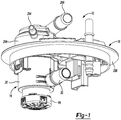
Figure 1 is a perspective view of an exemplary liquid vapor separator drain valve (LVSDV) assembly in accordance with the principles of the present disclosure; -
Figure 2 is a perspective view of an exemplary liquid vapor separator drain valve of the LVSDV assembly ofFigure 1 in accordance with the principles of the present disclosure; -
Figure 2A is an exploded or assembly view of the LVSDV ofFigure 2 in accordance with the principles of the present disclosure; -
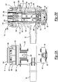
Figure 3A is a side view of the LVSDV ofFigure 2 in accordance with the principles of the present disclosure; -
Figure 3B is a sectional view of the LVSDV ofFigure 3A in accordance with the principles of the present disclosure; -
Figure 4 is a bottom perspective view of a flange housing of the LVSDV assembly ofFigure 1 in accordance with the principles of the present disclosure; -
Figure 5 is a top perspective view of the flange housing in accordance with the principles of the present disclosure; -
Figure 6 is a sectional view of the LVSDV assembly in accordance with the principles of the present disclosure; and -
Figure 7 is a schematic view of an exemplary evaporative system for a vehicle including the LVSDV assembly in accordance with the principles of the present disclosure. - With initial reference to
Figure 1 , an exemplary liquid vapor separator drain valve (LVSDV) assembly is shown and generally identified atreference numeral 10. In accordance with various aspects of the invention, theLVSDV assembly 10 includes aLVSDV 14 and a flange member orhousing 18 that is removably sealingly coupled to a fuel tank (Figure 7 ). In this implementation, theflange member 18 is also configured to removably and sealingly receive theLVSDV 14 in a snap-fit configuration. As will be discussed in greater detail below, theLVSDV assembly 10 provides for allowing fuel vapor to vent to a carbon canister while protecting the carbon canister from liquid fuel. In one exemplary implementation, theLVSDV assembly 10 interfaces with a fuel delivery module and various fuel tank vent valves while the LVSDV 14 is packaged in the fuel tank. - In accordance with various aspects of the invention, the
LVSDV assembly 10 is advantageously configured in a more compact and less complex manner thereby reducing cost and complexity of the vehicle fuel and evaporative systems while also reducing packaging space required within the fuel tank. This thereby provides for using a smaller fuel tank and/or positioning theLVSDV 14 in the fuel tank while allowing fuel to rise higher than with conventional larger and more bulky vent valves. By providing a single device (i.e., the LVSDV assembly 10) with multiple functions, less connections with the fuel tank are required and those connections are confined within the fuel tank via theLVSDV assembly 10, which reduces complexity and potential leak paths. - For example and as will be discussed in greater detail below, the fuel vapor vent valves are routed through the
LVSDV assembly 10 such that theLVSDV 14 can capture any liquid carry over (LCO) and thereby protect a carbon canister from potential fuel contamination. TheLVSDV assembly 10 is configured to coalesce LCO if present in the vapor venting lines of the evaporative and/or fuel systems. In addition, in one exemplary implementation, theLVSDV assembly 10 is configured to drain LCO with an integrated roll over drain valve, protect for a failed nozzle scenario, protect the evaporative system with a liquid trap design, and provide for venting with LCO in vapor venting lines and fuel in the liquid separation chamber. - Continuing with reference to
Figure 1 and with additional reference toFigures 2-3B , theLVSDV 14 includes, in one exemplary implementation, an outer body orhousing 26 defining anexternal port 30 configured to be fluidly coupled to a fill limit vapor valve (FLW) 34 of an exemplaryevaporative system 38 schematically shown inFigure 7 . Theouter body 26 defines an upperinternal chamber 46 separated by adivider member 50 from a lowerinternal chamber 54. Thedivider member 50 includes at least onepassage 58 to provide selective fluid communication between thechambers outer body 26 also defines an openupper end 64, which forms an open upper end ofchamber 46, and a loweropen end 68, which forms a lower open end ofchamber 54. In the exemplary implementation illustrated, thehousing 26 includes a cylindrical shape such that the upper and lowerinternal chambers upper chamber 46 having a longer axial length than thelower chamber 54, as can be seen for example inFigures 3A-3B . - A
lower valve 76 is movably positioned in thelower chamber 54 and, in one exemplary implementation, is balanced by abiasing member 80. In one exemplary implementation, thelower valve 76 is a float valve. A cap orclosure member 84 is removably coupled to thelower end 68 ofhousing 26 so as to be positioned under thefloat 76. Thecap 84 is configured to support and/or capture thefloat 76 inlower chamber 54. In one exemplary implementation, thecap 84 is perforated and is configured to be removably snap-fit to theouter body 26 via tabs orcutouts 88 formed in anouter rim 92 ofcap 84 and correspondingangled projections 98 formed onouter body 26. - An upper end or
side 102 of thefloat 76 includes aseal 106 configured to, when urged upward by liquid fuel, seal against thedivider member 50 so as to block orseal passage 58 and thereby seal lowerinternal chamber 54 from upperinternal chamber 46. Theseal 106, in the exemplary implementation illustrated, includes ahousing 110 movably coupled to thefloat 76 to provide an ability for theseal 106 to move relative to thefloat 76 in a situation where, for example, the liquid fuel urging thefloat 76 upward toward thedivider member 50 provides an angled force on thefloat 76. - The LVSDV 14 includes an
upper housing member 124 that is removably coupled to theouter housing 26, as shown for example inFigures 2A-3B . Theupper housing member 124 includes abody 128 defining anupper end 134, alower end 138 and a radially extendingflange 142. The radially extendingflange 142 defines tworeceptacles 146 configured to receive two tabs orprojections 152 axially extending from theupper end 64 ofouter housing 26 to removably couple theupper housing member 124 to theouter housing 26. When theupper housing member 124 is removably coupled to theouter housing 26, aportion 156 of thebody 128 between theflange 142 and thelower end 138 is positioned inside theupper chamber 46 such that thelower end 138 engages or rests on thedivider member 50. Thebody 128 includes a smaller diameter than upperinternal chamber 46 so as to be spaced apart therefrom when positioned therein and form achamber area 162 between theouter housing 26 and thebody 128 ofupper housing member 124. In one exemplary implementation, theupper housing member 124 partitions theupper chamber 46 into anouter chamber 162 between theouter housing 26 and theupper housing body 128 and aninternal chamber area 172 inside thebody 128. - The
lower end 138 ofupper housing member 124 includes one or more cut-outs or recesses 168 so as to form a fluid communication path between theouter chamber area 162 and theinternal chamber area 172 insidecylindrical body 128 whenupper housing member 124 is assembled toouter housing 26. Theupper end 134 ofhousing member 124 defines a central opening orport 176 in communication with theinternal chamber 172 defined by thebody 128 ofhousing member 124. Theradial extending flange 142 defines one or more peripheral apertures orpassages 184 spaced radially outward from theport 176 and thebody 128 and configured to be in fluid communication with outer chamber area orportion 162 whenhousing member 124 is assembled toouter body 26. A radially outer portion of theradially extending flange 142 engages theupper end 64 ofhousing 26 when theupper housing member 124 is assembled thereto. - An
upper valve 194 is positioned insideupper housing member 124 in theinternal chamber 172 and includes abody 198 defining anupper end 202 and alower end 206 having cut-outs or recesses 210. In one exemplary implementation, theupper valve 194 is an upper float valve that is configured to engage or rest ondivider member 50 via thelower end 206 when positioned inLVSDV 14. Theupper end 202 includes a smaller width ordiameter 214 than alower portion 218 and includes aseal 224 movably coupled thereto, such that when theupper valve 194 is urged upward by liquid fuel, theseal 224 is configured to seal against theupper end 134 ofhousing member 124 thereby sealing or closing offport 176. Theupper housing member 124 can also define one or moreperipheral passages 234 in thebody 128 and above theflange 142 proximate theupper end 134. Thesepassages 234 provide a fluid communication path throughbody 128 and ultimately topassage 58 ofdivider 50 via a space between theupper housing member 124 andupper float valve 194 regardless of a position of theupper float valve 194. - As can be seen in
Figures 2A and3B , theLVSDV 14 includes two in-line (i.e., common central axis), vertically stacked floats orfloat valves lower valves upper float valve 194 includes a generally up-side-down U-shape configuration defining aninternal chamber 244 having a diameter or width slightly smaller than the corresponding diameter or width of surroundinginternal chamber 172. In a rest condition,float valve 194 is vertically spaced apart from theupper end 134 ofupper housing member 124 and thusport 176. Fluid, such as fuel, enteringchambers upper float valve 194 upward into sealing engagement with theupper end 134 of housing member 24 thereby sealing offport 176 from the carbon canister. - With particular reference to
Figures 4-7 and continuing reference toFigures 1-3B , the flange member orhousing 18 will now be discussed in greater detail. As briefly mentioned above, theLVSDV 14 can be removably coupled to theflange member 18, which is sealingly connected to afuel tank 250 and in fluid communication with aninternal volume 254 defined thereby, as shown inFigure 7 . Theflange member 18 includes abody 260 defining a raised receptacle orcavity 264 configured to receive theLVSDV 14. Thereceptacle 264 includes a firstinternal wall 272 and a second, smaller diameterinternal wall 276. In one exemplary implementation, the secondinternal wall 276 is positioned above the firstinternal wall 272, which may be in or below thereceptacle 264. - A
first flange port 284 extends from and/or is in communication with an aperture or opening in thefirst wall 272 and asecond flange port 288 extends from an area defined by or above the secondinternal wall 276. Athird port 292 extends from a bottom offlange member 18 and is in communication with thefirst port 284. The first andsecond flange ports receptacle 264 oradjacent body 260 while being fluidly coupled to different chambers when theflange member 18 is coupled to theLVSDV 14. In the exemplary implementation illustrated, the first andsecond flange ports body 260 and are vertically and horizontally spaced apart from each other. For example, thesecond flange port 288 is positioned above thefirst flange port 284. Such a configuration can provide for, among other advantages, a morecompact flange member 18 for vehicle packaging purposes. Theflange member body 260 also defines aperimeter flange area 296 for removable sealingly coupling theflange member 18 to thefuel tank 250, as shown for example inFigure 7 . - The
LVSDV 14, when assembled together, includes afirst seal 304, such as an o-ring, proximate an upper end of theouter body 26, and asecond seal 308, such as an o-ring, proximate theupper end 134 of theupper housing member 124, as shown for example inFigure 3B . The first andsecond seals second seal 308 is vertically and horizontally spaced apart from thefirst seal 304. With this sealing configuration, theLVSDV 14, when assembled to theflange member 18, automatically seals against theflange member 18 and automatically separates the LVSDV chambers associated with the first andsecond ports - For example, the
first seal 304 seals to or against the firstinternal wall 272 and thesecond seal 308 seals to or against the secondinternal wall 276. This places, among other things, thefirst port 284 in communication with theouter chamber area 162 betweenouter body 26 andupper housing member 124 viaperipheral passages 184; thesecond port 288 in communication withupper end port 176; and thethird port 292 in communication with thesecond port 288 andupper end port 176. With this configuration, theupper valve 194 can seal off theupper port 176 and thus communication with the carbon canister viaport 288 while allowing thefirst port 284 to communicate with theouter chamber area 162. In addition, thesecond port 288 can also communicate with theouter chamber area 162 and thus drain liquid fuel independent from theupper port 176 because thesecond port 288 is lower than thefirst port 284 and associated with theouter chamber 162. TheLVSDV 14 is, in one exemplary implementation, removably coupled to theflange member 18 by guiding theupper end 134 ofupper housing member 124 into thereceptacle 264 such that tabs orprojections 298 on an exterior ofouter body 26 are received in a recess or cutout ofprojections 300 extending from a lower side orsurface 312 offlange member 18. - Operation of the
LVSDV 14 will now be discussed in conjunction with theflange member 18 and the exemplary evaporative system shown inFigure 7 . In one exemplary aspect, thethird flange port 292 is fluidly coupled to a remote mountedgrade vent valve 318, which is desirably positioned higher in thefuel tank 250 relative to theLVSDV 14. Thefirst flange port 284 is fluidly coupled to the fuel filltube recirculation line 324 and thesecond flange port 288 is fluidly coupled to thecarbon canister 328. As mentioned above, thethird flange port 292 is in communication with thesecond flange port 288 outside of and/or independent of theLVSDV 14. TheLVSDV 14external port 30 is in fluid communication with the fill limit vapor valve (FLW) 34, which is positioned in thefuel tank 250. - In the exemplary implementation illustrated, the
external port 30 is configured to provide a main vapor release path for the fuel tank system. In operating conditions where thefloat valves portion 162 ofupper chamber 46 viaexternal port 30 and flow through the flangeperipheral passages 184, throughradial wall passages 234 inupper housing member 124, throughport 176, and out flangeport 288 toward thecarbon canister 328. Fuel vapor can also flow intochamber 172 ofupper valve 124 via theperforated cap 84, lowerinternal chamber 54 andpassage 58 individer member 50. - If liquid fuel flows down the
recirculation tube 324 and enters theLVSDV 14 viaflange port 284, it can be diverted from a flow path toward thecarbon canister 328 by theLVSDV assembly 10. More particularly, in the exemplary implementation illustrated, such liquid fuel flow from therecirculation tube 324 leavesflange port 284 and flows throughperipheral flange passages 184 and intochamber portion 162, where the fuel can flow into theinternal chamber 244 via the cut-outs housing member 124 andfloat valve 194, respectively. The liquid fuel then drains throughpassage 58 and the perforations incap 84. If the volume of liquid fuel flowing intochamber 244 in the manner discussed above is greater than the drain rate, then theupper float valve 194 will be urged upward and seal offport 176 to protect thecarbon canister 328. Withport 176 sealed off, the liquid fuel from therecirculation tube 324 is not able to reachsecond flange port 288 and thus thecarbon canister 328, but can still drain to the fuel tank. - If the vehicle is on a grade and the FLVV 34 would potentially leak or malfunction, the
upper float valve 194 can act as a back-up to prevent liquid fuel from reaching thecarbon canister 328. To the extent such a scenario would happen, fuel entering the FLVV 34 could potentially reach the LVSDV 14 viaexternal port 30. In this situation, the liquid fuel would enterchamber 244 via the cut-outs and, to the extent the fuel enters at a rate greater than it drains, seal 224 would be urged againstupper end 134 viafloat 194 to seal offport 58. This would again, in a similar manner as discussed above, prevent such fuel from reaching thecarbon canister 328. - In a potential scenario where the
LVSDV 14 and FLVV 34 are submerged in liquid fuel, to the extent possible without a roll-over condition, theLVSDV 14 would seal off any potential for liquid fuel to enter thecarbon canister 328 via theLVSDV 14, while the remotegrade vent valve 318 would provide for venting of thefuel tank 250 vapor to thecarbon canister 328. While thefloat valves ports LVSDV 14, the remotegrade vent valve 318 is positioned and plumbed to theLVSDV 14 viathird flange port 292 such that the fuel tank would still be able to vent fuel vapor via thethird flange port 292 andsecond flange port 288. In this regard, and as can be seen inFigure 7 , the remotegrade vent valve 318 is positioned at or substantially at an opposite side of thefuel tank 250 as theLVSDV 14, and mounted higher (toward a top of fuel tank 250).
Claims (15)
- A liquid vapor separator drain valve (LVSDV) assembly (10) for a fuel tank (250) of a vehicle, comprising:
a LVSDV (14) adapted to be positioned in the fuel tank, the LVSDV including:an outer housing (26) defining upper (46) and lower (54) chambers separated by a divider member (50) having a vent passage (58);an upper housing (124) coupled to the outer housing and having a body (128) positioned in the upper chamber thereby partitioning the upper chamber into an outer chamber (162) and an inner chamber (172), the upper housing defining an upper port (176) adapted to be in communication with a carbon canister (328), the outer housing defining an external port (30) in communication with the outer chamber and adapted to be in communication with a fill limit vapor valve (34); anda lower valve (76) movably positioned in the lower chamber and an upper valve (194) movably positioned in the inner chamber, wherein the upper and lower chambers and the upper and lower valves are positioned in a vertically stacked, concentric arrangement;wherein the lower valve is operable to vent fuel vapor from the fuel tank to the upper chamber in a rest position and seal off the vent passage when liquid fuel reaches a lower predetermined level, and the upper valve is operable to vent fuel vapor to the upper port i) from the vent passage and ii) from the external port when liquid fuel is above or below the lower predetermined level, and to seal off the upper port when liquid fuel is above an upper predetermined level greater than the lower predetermined level. - The valve assembly of claim 1, further comprising a flange housing (14) adapted to be removably secured to the fuel tank, the flange housing defining a receptacle (264) for coupling the LVSDV thereto.
- The valve assembly of claim 2, wherein the flange housing further comprises:an upper vent port (288) extending from the receptacle and in communication with the upper port and adapted to be in communication with the carbon canister for venting fuel vapor from the LVSDV to the carbon canister; anda lower vent port (284) in communication with the upper housing and adapted to be in communication with a fuel filler tube recirculation line (324).
- The valve assembly of claim 3, wherein the upper vent port and the lower vent port are vertically and horizontally spaced apart from each other so as to be in direct communication with different chambers defined by the LVSDV upon coupling the LVSDV to the flange housing.
- The valve assembly of claim 4, wherein the outer housing defines an outer housing diameter larger than an upper housing diameter defined by the upper housing; and
wherein the outer housing includes an outer housing seal (304) positioned proximate an upper end (64) thereof, and the upper housing includes an upper housing seal (308) positioned proximate an upper end (134) thereof, the outer housing seal positioned vertically and horizontally spaced apart from the upper housing seal. - The valve assembly of claim 5, wherein upon coupling the LVSDV to the flange housing, the outer and upper housing seals each engage the receptacle thereby placing the upper vent port in direct communication with the upper port and inner chamber and the lower vent port in direct communication with the outer chamber.
- The valve assembly of claim 6, wherein the receptacle defines an inner wall (276) and an outer wall (272), the inner wall being positioned between the upper and lower vent ports and having a smaller diameter than the outer wall, which is positioned at or below the lower vent port; and
wherein upon coupling the LVSDV to the flange housing, the upper housing seal engages the inner wall and the outer housing seal engages the outer wall. - The valve assembly of claim 1, wherein the lower valve comprises a float valve (76) including a body (102) and a seal (106) movably coupled to an upper end of the body and configured to seal off the vent passage when liquid fuel reaches the lower predetermined level.
- The valve assembly of claim 1, wherein the upper valve is positioned inside the body of the upper housing and includes a longitudinal length less than a corresponding longitudinal length of the upper housing.
- The valve assembly of claim 9, wherein the upper valve comprises a float valve including:a cylindrical body (198) defining an internal chamber and an open lower end (206) configured to engage the divider member in a rest position; andan upper valve seal (224) positioned on an upper end (202) of the cylindrical body opposite the lower end of the cylindrical body;wherein when liquid fuel fills the internal chamber, the upper valve is configured to move from the rest position such that the upper valve seal engages and seals off the upper port.
- The valve assembly of claim 1, wherein the upper housing includes an upper housing diameter smaller than an outer housing diameter of the outer housing; and
wherein the upper housing includes a radially extending flange (142) configured to extend to and engage the upper end of the outer housing upon coupling the outer housing to the upper housing. - The valve assembly of claim 11, wherein the radially extending flange includes one or more flange apertures (184) in communication with the outer chamber thereby providing a first flow path for liquid fuel entering the lower vent port to flow through the one or more flange apertures and into the outer chamber.
- The valve assembly of claim 12, wherein the body of the upper housing defines one or more body apertures (234) positioned between the upper port and the radially extending flange, the one or more body apertures being in communication with the inner chamber and providing a second flow path for liquid fuel entering the lower vent port to flow through the one or more body apertures into the inner chamber when the upper valve moves form a rest position to a sealing position closing the upper port.
- The valve assembly of claim 3, further comprising a third vent port (292) extending from the receptacle and in communication with the upper port and adapted to be in communication with a grade vent valve (318) positioned in the fuel tank.
- The valve assembly of claim 14, wherein the third vent port extends from the receptacle at a position above the upper port when the LVSDV is coupled to the flange housing and provides a vent path for fuel vapor when the lower valve seals off the vent passage and the upper valve seals off the upper port.
Applications Claiming Priority (3)
| Application Number | Priority Date | Filing Date | Title |
|---|---|---|---|
| US201361901158P | 2013-11-07 | 2013-11-07 | |
| US14/530,075 US9428043B2 (en) | 2013-11-07 | 2014-10-31 | Liquid vapor separator drain valve |
| PCT/US2014/064203 WO2015069816A1 (en) | 2013-11-07 | 2014-11-06 | Liquid vapor separator drain valve |
Publications (2)
| Publication Number | Publication Date |
|---|---|
| EP3065963A1 EP3065963A1 (en) | 2016-09-14 |
| EP3065963B1 true EP3065963B1 (en) | 2019-01-09 |
Family
ID=53006099
Family Applications (1)
| Application Number | Title | Priority Date | Filing Date |
|---|---|---|---|
| EP14802555.4A Active EP3065963B1 (en) | 2013-11-07 | 2014-11-06 | Liquid vapor separator drain valve |
Country Status (6)
| Country | Link |
|---|---|
| US (1) | US9428043B2 (en) |
| EP (1) | EP3065963B1 (en) |
| CN (1) | CN105705361B (en) |
| CA (1) | CA2929416C (en) |
| MX (1) | MX368176B (en) |
| WO (1) | WO2015069816A1 (en) |
Families Citing this family (9)
| Publication number | Priority date | Publication date | Assignee | Title |
|---|---|---|---|---|
| US10035091B2 (en) * | 2014-03-17 | 2018-07-31 | Kyosan Denki Co., Ltd. | Liquid fuel catcher |
| GB2544004B (en) * | 2014-08-25 | 2020-05-06 | Piolax Inc | Valve case mounting structure |
| CN105888889B (en) * | 2016-05-26 | 2018-05-11 | 宁波拓普智能刹车系统有限公司 | A kind of gasoline vapor purifier with backflow functionality |
| JP6841251B2 (en) | 2018-02-23 | 2021-03-10 | 豊田合成株式会社 | Fuel valve |
| CN110843507A (en) * | 2018-08-20 | 2020-02-28 | 上海汽车集团股份有限公司 | Vehicles and their high-pressure fuel tanks |
| WO2020119943A1 (en) * | 2018-12-10 | 2020-06-18 | Eaton Intelligent Power Limited | Evaporative emissions fuel tank venting system with pressure relief and solenoid actuation |
| KR102644618B1 (en) * | 2019-05-22 | 2024-03-06 | 현대자동차주식회사 | Vent valve for closed tank |
| WO2020253995A1 (en) * | 2019-06-20 | 2020-12-24 | Eaton Intelligent Power Limited | Evaporative emissions fuel tank venting system with mechanical liquid detection |
| CN114320673A (en) * | 2020-10-09 | 2022-04-12 | 通用汽车环球科技运作有限责任公司 | Evaporative emission system |
Family Cites Families (17)
| Publication number | Priority date | Publication date | Assignee | Title |
|---|---|---|---|---|
| JPH07132740A (en) * | 1993-11-05 | 1995-05-23 | Toyoda Gosei Co Ltd | Fuel vapor processing device |
| US5413137A (en) | 1994-02-14 | 1995-05-09 | Borg-Warner Automotive, Inc. | Fuel vapor vent assembly with liquid trap |
| US5669361A (en) | 1996-02-15 | 1997-09-23 | Borg-Warner Automotive, Inc. | Vehicle refueling valve |
| US6311675B2 (en) | 1999-04-28 | 2001-11-06 | Walbro Corporation | Vent valve and fuel pump module |
| US6915812B2 (en) | 2000-09-12 | 2005-07-12 | Alfmeier Corporation | Low permeation weldable fuel tank assembly |
| US20030075049A1 (en) | 2001-10-19 | 2003-04-24 | Larsen Michael T. | Gas/liquid separator including a liquid trap filter |
| US20030094458A1 (en) * | 2001-11-19 | 2003-05-22 | Sharon Elizabeth Beyer | Fuel delivery module cover assembly |
| US6675779B2 (en) | 2002-06-13 | 2004-01-13 | Stant Manufacturing Inc. | Dual float valve for fuel tank vent with liquid carryover filter |
| EP1488947A3 (en) | 2003-06-16 | 2005-06-15 | Stant Manufacturing Inc. | Fuel tank vent system with liquid fuel filter |
| US7163023B2 (en) * | 2004-07-15 | 2007-01-16 | Eaton Corporation | Fuel vapor vent valve float assembly and method of making same |
| US7201155B2 (en) * | 2005-03-15 | 2007-04-10 | Eaton Corporation | Integral vapor storage and vent valve assembly for use with a small engine fuel tank and vapor emission system employing same |
| US8171952B2 (en) | 2008-02-01 | 2012-05-08 | Eaton Corporation | Multi-function control valve for fuel vapor system |
| KR100969388B1 (en) * | 2008-08-14 | 2010-07-09 | 현대자동차주식회사 | Vehicle fuel supply system |
| EP2611639B1 (en) * | 2010-09-02 | 2014-10-15 | Raval A.C.S. LTD | Roll over valve |
| US9109551B2 (en) | 2011-05-24 | 2015-08-18 | Eaton Corporation | Liquid trap for fuel vapor valve |
| US8689816B2 (en) * | 2011-12-22 | 2014-04-08 | Eaton Corporation | Fuel tank vent valve assembly and method of assembly |
| US9365107B2 (en) * | 2012-08-31 | 2016-06-14 | Stant Usa Corp. | Fuel tank vent apparatus |
-
2014
- 2014-10-31 US US14/530,075 patent/US9428043B2/en active Active
- 2014-11-06 CN CN201480061020.8A patent/CN105705361B/en active Active
- 2014-11-06 WO PCT/US2014/064203 patent/WO2015069816A1/en not_active Ceased
- 2014-11-06 EP EP14802555.4A patent/EP3065963B1/en active Active
- 2014-11-06 CA CA2929416A patent/CA2929416C/en active Active
- 2014-11-06 MX MX2016006013A patent/MX368176B/en active IP Right Grant
Non-Patent Citations (1)
| Title |
|---|
| None * |
Also Published As
| Publication number | Publication date |
|---|---|
| CA2929416C (en) | 2021-06-22 |
| CA2929416A1 (en) | 2015-05-14 |
| EP3065963A1 (en) | 2016-09-14 |
| CN105705361A (en) | 2016-06-22 |
| US20150122347A1 (en) | 2015-05-07 |
| WO2015069816A1 (en) | 2015-05-14 |
| MX2016006013A (en) | 2016-08-12 |
| CN105705361B (en) | 2018-07-24 |
| US9428043B2 (en) | 2016-08-30 |
| MX368176B (en) | 2019-09-23 |
Similar Documents
| Publication | Publication Date | Title |
|---|---|---|
| CA2929416C (en) | Liquid vapor separator drain valve | |
| US6866058B1 (en) | Fuel tank vent system with liquid fuel filter | |
| KR101638217B1 (en) | Small engine emissions control valve | |
| EP1212560B1 (en) | Valve and method for fitting it to a tank | |
| EP2607135B1 (en) | Fuel ventilation system valve | |
| JP6446002B2 (en) | Fuel shut-off valve | |
| RU2412830C2 (en) | Separator of liquid fuel from vapours and transport facility fuel system | |
| JP2000320416A (en) | Multi-function fuel pump module | |
| JP2004052686A (en) | Complex type air vent valve and air vent mechanism for fuel tank | |
| JP6106073B2 (en) | Flap valve device and gas-liquid separator equipped with flap valve device | |
| KR101733827B1 (en) | Vehicle fuel system and components thereof | |
| US8490603B2 (en) | Fuel tank valve device and fuel tank ventilation device | |
| CN105992706B (en) | Valve device | |
| KR20090040432A (en) | Venting piping system for fuel tank | |
| MX2014005208A (en) | Filter device and arrangement for ventilating a tank comprising a filter device. | |
| JP2004257264A (en) | Full tank control valve structure | |
| KR102039656B1 (en) | Vlave device for fuel tank | |
| US10792598B2 (en) | Breather | |
| US10906391B2 (en) | Fuel tank having inlet check valve | |
| JP2014508878A (en) | Fuel valve | |
| US8261947B2 (en) | Portable fuel container emissions control | |
| WO2015127477A1 (en) | Fuel tank liquid vapor discriminator with integrated over-pressure and make-up air valves | |
| EP1488947A2 (en) | Fuel tank vent system with liquid fuel filter | |
| JP6070453B2 (en) | Fuel shut-off device | |
| JP2016191339A (en) | Fuel supply device |
Legal Events
| Date | Code | Title | Description |
|---|---|---|---|
| PUAI | Public reference made under article 153(3) epc to a published international application that has entered the european phase |
Free format text: ORIGINAL CODE: 0009012 |
|
| 17P | Request for examination filed |
Effective date: 20160429 |
|
| AK | Designated contracting states |
Kind code of ref document: A1 Designated state(s): AL AT BE BG CH CY CZ DE DK EE ES FI FR GB GR HR HU IE IS IT LI LT LU LV MC MK MT NL NO PL PT RO RS SE SI SK SM TR |
|
| AX | Request for extension of the european patent |
Extension state: BA ME |
|
| DAX | Request for extension of the european patent (deleted) | ||
| GRAP | Despatch of communication of intention to grant a patent |
Free format text: ORIGINAL CODE: EPIDOSNIGR1 |
|
| STAA | Information on the status of an ep patent application or granted ep patent |
Free format text: STATUS: GRANT OF PATENT IS INTENDED |
|
| INTG | Intention to grant announced |
Effective date: 20180625 |
|
| GRAS | Grant fee paid |
Free format text: ORIGINAL CODE: EPIDOSNIGR3 |
|
| GRAA | (expected) grant |
Free format text: ORIGINAL CODE: 0009210 |
|
| STAA | Information on the status of an ep patent application or granted ep patent |
Free format text: STATUS: THE PATENT HAS BEEN GRANTED |
|
| AK | Designated contracting states |
Kind code of ref document: B1 Designated state(s): AL AT BE BG CH CY CZ DE DK EE ES FI FR GB GR HR HU IE IS IT LI LT LU LV MC MK MT NL NO PL PT RO RS SE SI SK SM TR |
|
| REG | Reference to a national code |
Ref country code: GB Ref legal event code: FG4D |
|
| REG | Reference to a national code |
Ref country code: CH Ref legal event code: EP Ref country code: AT Ref legal event code: REF Ref document number: 1086845 Country of ref document: AT Kind code of ref document: T Effective date: 20190115 |
|
| REG | Reference to a national code |
Ref country code: IE Ref legal event code: FG4D |
|
| REG | Reference to a national code |
Ref country code: DE Ref legal event code: R096 Ref document number: 602014039669 Country of ref document: DE |
|
| REG | Reference to a national code |
Ref country code: NL Ref legal event code: MP Effective date: 20190109 |
|
| REG | Reference to a national code |
Ref country code: LT Ref legal event code: MG4D |
|
| PG25 | Lapsed in a contracting state [announced via postgrant information from national office to epo] |
Ref country code: NL Free format text: LAPSE BECAUSE OF FAILURE TO SUBMIT A TRANSLATION OF THE DESCRIPTION OR TO PAY THE FEE WITHIN THE PRESCRIBED TIME-LIMIT Effective date: 20190109 |
|
| REG | Reference to a national code |
Ref country code: AT Ref legal event code: MK05 Ref document number: 1086845 Country of ref document: AT Kind code of ref document: T Effective date: 20190109 |
|
| PG25 | Lapsed in a contracting state [announced via postgrant information from national office to epo] |
Ref country code: NO Free format text: LAPSE BECAUSE OF FAILURE TO SUBMIT A TRANSLATION OF THE DESCRIPTION OR TO PAY THE FEE WITHIN THE PRESCRIBED TIME-LIMIT Effective date: 20190409 Ref country code: FI Free format text: LAPSE BECAUSE OF FAILURE TO SUBMIT A TRANSLATION OF THE DESCRIPTION OR TO PAY THE FEE WITHIN THE PRESCRIBED TIME-LIMIT Effective date: 20190109 Ref country code: PL Free format text: LAPSE BECAUSE OF FAILURE TO SUBMIT A TRANSLATION OF THE DESCRIPTION OR TO PAY THE FEE WITHIN THE PRESCRIBED TIME-LIMIT Effective date: 20190109 Ref country code: LT Free format text: LAPSE BECAUSE OF FAILURE TO SUBMIT A TRANSLATION OF THE DESCRIPTION OR TO PAY THE FEE WITHIN THE PRESCRIBED TIME-LIMIT Effective date: 20190109 Ref country code: PT Free format text: LAPSE BECAUSE OF FAILURE TO SUBMIT A TRANSLATION OF THE DESCRIPTION OR TO PAY THE FEE WITHIN THE PRESCRIBED TIME-LIMIT Effective date: 20190509 Ref country code: ES Free format text: LAPSE BECAUSE OF FAILURE TO SUBMIT A TRANSLATION OF THE DESCRIPTION OR TO PAY THE FEE WITHIN THE PRESCRIBED TIME-LIMIT Effective date: 20190109 Ref country code: SE Free format text: LAPSE BECAUSE OF FAILURE TO SUBMIT A TRANSLATION OF THE DESCRIPTION OR TO PAY THE FEE WITHIN THE PRESCRIBED TIME-LIMIT Effective date: 20190109 |
|
| PG25 | Lapsed in a contracting state [announced via postgrant information from national office to epo] |
Ref country code: LV Free format text: LAPSE BECAUSE OF FAILURE TO SUBMIT A TRANSLATION OF THE DESCRIPTION OR TO PAY THE FEE WITHIN THE PRESCRIBED TIME-LIMIT Effective date: 20190109 Ref country code: GR Free format text: LAPSE BECAUSE OF FAILURE TO SUBMIT A TRANSLATION OF THE DESCRIPTION OR TO PAY THE FEE WITHIN THE PRESCRIBED TIME-LIMIT Effective date: 20190410 Ref country code: HR Free format text: LAPSE BECAUSE OF FAILURE TO SUBMIT A TRANSLATION OF THE DESCRIPTION OR TO PAY THE FEE WITHIN THE PRESCRIBED TIME-LIMIT Effective date: 20190109 Ref country code: RS Free format text: LAPSE BECAUSE OF FAILURE TO SUBMIT A TRANSLATION OF THE DESCRIPTION OR TO PAY THE FEE WITHIN THE PRESCRIBED TIME-LIMIT Effective date: 20190109 Ref country code: IS Free format text: LAPSE BECAUSE OF FAILURE TO SUBMIT A TRANSLATION OF THE DESCRIPTION OR TO PAY THE FEE WITHIN THE PRESCRIBED TIME-LIMIT Effective date: 20190509 Ref country code: BG Free format text: LAPSE BECAUSE OF FAILURE TO SUBMIT A TRANSLATION OF THE DESCRIPTION OR TO PAY THE FEE WITHIN THE PRESCRIBED TIME-LIMIT Effective date: 20190409 |
|
| REG | Reference to a national code |
Ref country code: DE Ref legal event code: R097 Ref document number: 602014039669 Country of ref document: DE |
|
| PG25 | Lapsed in a contracting state [announced via postgrant information from national office to epo] |
Ref country code: DK Free format text: LAPSE BECAUSE OF FAILURE TO SUBMIT A TRANSLATION OF THE DESCRIPTION OR TO PAY THE FEE WITHIN THE PRESCRIBED TIME-LIMIT Effective date: 20190109 Ref country code: AL Free format text: LAPSE BECAUSE OF FAILURE TO SUBMIT A TRANSLATION OF THE DESCRIPTION OR TO PAY THE FEE WITHIN THE PRESCRIBED TIME-LIMIT Effective date: 20190109 Ref country code: RO Free format text: LAPSE BECAUSE OF FAILURE TO SUBMIT A TRANSLATION OF THE DESCRIPTION OR TO PAY THE FEE WITHIN THE PRESCRIBED TIME-LIMIT Effective date: 20190109 Ref country code: SK Free format text: LAPSE BECAUSE OF FAILURE TO SUBMIT A TRANSLATION OF THE DESCRIPTION OR TO PAY THE FEE WITHIN THE PRESCRIBED TIME-LIMIT Effective date: 20190109 Ref country code: CZ Free format text: LAPSE BECAUSE OF FAILURE TO SUBMIT A TRANSLATION OF THE DESCRIPTION OR TO PAY THE FEE WITHIN THE PRESCRIBED TIME-LIMIT Effective date: 20190109 Ref country code: EE Free format text: LAPSE BECAUSE OF FAILURE TO SUBMIT A TRANSLATION OF THE DESCRIPTION OR TO PAY THE FEE WITHIN THE PRESCRIBED TIME-LIMIT Effective date: 20190109 Ref country code: AT Free format text: LAPSE BECAUSE OF FAILURE TO SUBMIT A TRANSLATION OF THE DESCRIPTION OR TO PAY THE FEE WITHIN THE PRESCRIBED TIME-LIMIT Effective date: 20190109 |
|
| PLBE | No opposition filed within time limit |
Free format text: ORIGINAL CODE: 0009261 |
|
| STAA | Information on the status of an ep patent application or granted ep patent |
Free format text: STATUS: NO OPPOSITION FILED WITHIN TIME LIMIT |
|
| PG25 | Lapsed in a contracting state [announced via postgrant information from national office to epo] |
Ref country code: SM Free format text: LAPSE BECAUSE OF FAILURE TO SUBMIT A TRANSLATION OF THE DESCRIPTION OR TO PAY THE FEE WITHIN THE PRESCRIBED TIME-LIMIT Effective date: 20190109 |
|
| 26N | No opposition filed |
Effective date: 20191010 |
|
| PG25 | Lapsed in a contracting state [announced via postgrant information from national office to epo] |
Ref country code: SI Free format text: LAPSE BECAUSE OF FAILURE TO SUBMIT A TRANSLATION OF THE DESCRIPTION OR TO PAY THE FEE WITHIN THE PRESCRIBED TIME-LIMIT Effective date: 20190109 |
|
| PG25 | Lapsed in a contracting state [announced via postgrant information from national office to epo] |
Ref country code: TR Free format text: LAPSE BECAUSE OF FAILURE TO SUBMIT A TRANSLATION OF THE DESCRIPTION OR TO PAY THE FEE WITHIN THE PRESCRIBED TIME-LIMIT Effective date: 20190109 |
|
| REG | Reference to a national code |
Ref country code: CH Ref legal event code: PL |
|
| PG25 | Lapsed in a contracting state [announced via postgrant information from national office to epo] |
Ref country code: LU Free format text: LAPSE BECAUSE OF NON-PAYMENT OF DUE FEES Effective date: 20191106 Ref country code: CH Free format text: LAPSE BECAUSE OF NON-PAYMENT OF DUE FEES Effective date: 20191130 Ref country code: LI Free format text: LAPSE BECAUSE OF NON-PAYMENT OF DUE FEES Effective date: 20191130 Ref country code: MC Free format text: LAPSE BECAUSE OF FAILURE TO SUBMIT A TRANSLATION OF THE DESCRIPTION OR TO PAY THE FEE WITHIN THE PRESCRIBED TIME-LIMIT Effective date: 20190109 |
|
| REG | Reference to a national code |
Ref country code: BE Ref legal event code: MM Effective date: 20191130 |
|
| PG25 | Lapsed in a contracting state [announced via postgrant information from national office to epo] |
Ref country code: IE Free format text: LAPSE BECAUSE OF NON-PAYMENT OF DUE FEES Effective date: 20191106 |
|
| PG25 | Lapsed in a contracting state [announced via postgrant information from national office to epo] |
Ref country code: BE Free format text: LAPSE BECAUSE OF NON-PAYMENT OF DUE FEES Effective date: 20191130 |
|
| PG25 | Lapsed in a contracting state [announced via postgrant information from national office to epo] |
Ref country code: CY Free format text: LAPSE BECAUSE OF FAILURE TO SUBMIT A TRANSLATION OF THE DESCRIPTION OR TO PAY THE FEE WITHIN THE PRESCRIBED TIME-LIMIT Effective date: 20190109 |
|
| PG25 | Lapsed in a contracting state [announced via postgrant information from national office to epo] |
Ref country code: HU Free format text: LAPSE BECAUSE OF FAILURE TO SUBMIT A TRANSLATION OF THE DESCRIPTION OR TO PAY THE FEE WITHIN THE PRESCRIBED TIME-LIMIT; INVALID AB INITIO Effective date: 20141106 Ref country code: MT Free format text: LAPSE BECAUSE OF FAILURE TO SUBMIT A TRANSLATION OF THE DESCRIPTION OR TO PAY THE FEE WITHIN THE PRESCRIBED TIME-LIMIT Effective date: 20190109 |
|
| PG25 | Lapsed in a contracting state [announced via postgrant information from national office to epo] |
Ref country code: MK Free format text: LAPSE BECAUSE OF FAILURE TO SUBMIT A TRANSLATION OF THE DESCRIPTION OR TO PAY THE FEE WITHIN THE PRESCRIBED TIME-LIMIT Effective date: 20190109 |
|
| PGFP | Annual fee paid to national office [announced via postgrant information from national office to epo] |
Ref country code: DE Payment date: 20251128 Year of fee payment: 12 |
|
| PGFP | Annual fee paid to national office [announced via postgrant information from national office to epo] |
Ref country code: GB Payment date: 20251127 Year of fee payment: 12 |
|
| PGFP | Annual fee paid to national office [announced via postgrant information from national office to epo] |
Ref country code: IT Payment date: 20251119 Year of fee payment: 12 |
|
| PGFP | Annual fee paid to national office [announced via postgrant information from national office to epo] |
Ref country code: FR Payment date: 20251125 Year of fee payment: 12 |