EP3065823B1 - Cellulite and fat reducing device and method utilizing optical emitters - Google Patents
Cellulite and fat reducing device and method utilizing optical emitters Download PDFInfo
- Publication number
- EP3065823B1 EP3065823B1 EP14860875.5A EP14860875A EP3065823B1 EP 3065823 B1 EP3065823 B1 EP 3065823B1 EP 14860875 A EP14860875 A EP 14860875A EP 3065823 B1 EP3065823 B1 EP 3065823B1
- Authority
- EP
- European Patent Office
- Prior art keywords
- array
- output
- controller
- recipient
- approximately
- Prior art date
- Legal status (The legal status is an assumption and is not a legal conclusion. Google has not performed a legal analysis and makes no representation as to the accuracy of the status listed.)
- Active
Links
Images




Classifications
-
- A—HUMAN NECESSITIES
- A61—MEDICAL OR VETERINARY SCIENCE; HYGIENE
- A61N—ELECTROTHERAPY; MAGNETOTHERAPY; RADIATION THERAPY; ULTRASOUND THERAPY
- A61N5/00—Radiation therapy
- A61N5/06—Radiation therapy using light
- A61N5/0613—Apparatus adapted for a specific treatment
- A61N5/0616—Skin treatment other than tanning
-
- A—HUMAN NECESSITIES
- A61—MEDICAL OR VETERINARY SCIENCE; HYGIENE
- A61N—ELECTROTHERAPY; MAGNETOTHERAPY; RADIATION THERAPY; ULTRASOUND THERAPY
- A61N5/00—Radiation therapy
- A61N5/06—Radiation therapy using light
- A61N2005/0626—Monitoring, verifying, controlling systems and methods
-
- A—HUMAN NECESSITIES
- A61—MEDICAL OR VETERINARY SCIENCE; HYGIENE
- A61N—ELECTROTHERAPY; MAGNETOTHERAPY; RADIATION THERAPY; ULTRASOUND THERAPY
- A61N5/00—Radiation therapy
- A61N5/06—Radiation therapy using light
- A61N2005/0635—Radiation therapy using light characterised by the body area to be irradiated
- A61N2005/0642—Irradiating part of the body at a certain distance
-
- A—HUMAN NECESSITIES
- A61—MEDICAL OR VETERINARY SCIENCE; HYGIENE
- A61N—ELECTROTHERAPY; MAGNETOTHERAPY; RADIATION THERAPY; ULTRASOUND THERAPY
- A61N5/00—Radiation therapy
- A61N5/06—Radiation therapy using light
- A61N2005/065—Light sources therefor
- A61N2005/0651—Diodes
- A61N2005/0652—Arrays of diodes
-
- A—HUMAN NECESSITIES
- A61—MEDICAL OR VETERINARY SCIENCE; HYGIENE
- A61N—ELECTROTHERAPY; MAGNETOTHERAPY; RADIATION THERAPY; ULTRASOUND THERAPY
- A61N5/00—Radiation therapy
- A61N5/06—Radiation therapy using light
- A61N2005/0658—Radiation therapy using light characterised by the wavelength of light used
- A61N2005/0662—Visible light
Definitions
- the present description relates generally to the field of body shaping, and more particularly, to a device and method for reducing the appearance of cellulite utilizing optical emitters.
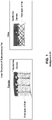
- FIG. 1 illustrates a side by side comparison of the fat cell structure within women and men. As shown, owing to the differences in the structure, cellulite is most commonly found in women, and typically forms about the thighs, hips, stomach and upper arms.
- cellulite and the resulting "cottage cheese” appearance of the skin do not react to these traditional methods.
- cellulite can be found in individuals of all body types having body mass indexes ranging from "normal” to "overweight” and "obese.”
- one approach may involve a user using creams such as those containing Caffeine or Aminophylline to temporarily reduce the appearance of cellulite.
- creams such as those containing Caffeine or Aminophylline
- maintenance is difficult to achieve and even harder to maintain, and even when results are good, and the recurring costs can be quite expensive.
- many of the lotions and creams that are applied topically can require multiple applications per week, can require the use of drugs or chemicals, can be irritating to the skin and must be used consistently over time to achieve then maintain desirable results.
- GB2442206 relates to a therapeutic light apparatus.
- WO2013070946 and WO2013134101 both relate to methods, devices and systems for delivering light therapy to human or non-human animal subjects.
- a cellulite and fat reducing device and method utilizing optical emitters comprising:
- Another embodiment can include components for modulating the power delivered to the array based on a reference waveform created internally or via an external device.
- Yet another embodiment of the present invention can include a cosmetic method for reducing the appearance of cellulite and fat on a recipient's body, said method comprising:
- cellulite and/or the appearance of cellulite deposits can be reduced through exposure to photonic energy that is applied by optical emitters at a target wavelength and for a specific duration of time.
- actual fat deposits can be reduced because subcutaneous adipocytes will expel their lipid content when treated with the below described system and method.
- a cellulite and fat reducing device and method utilizing optical emitters can act to decrease the existence and/or appearance of cellulite deposits, and can also function to remove fat deposits without permanent or adverse effects on the cells and their surrounding tissues.
- the device can illuminate the epidermis, dermis and subcutaneous fat tissue by applying light/radiation from an array of optical emitters at a target wavelength. Such exposure functions to tighten and smooth the skin, and to reduce the size of subcutaneous fat in the exposed areas (typically the thighs and buttocks). Modulation is not required, but may enhance results.
- optical emitter can include any form of light producing and/or emitting device having any number of different colors across the color spectrum.
- Several non-limiting examples can include Light Emitting Diodes (LED's), light emitting capacitors, and/or super-luminous light emitting diodes, for example, that are capable of individually and/or jointly creating optical emissions of light/radiation at a target wavelength.
- the below described array can utilize a plurality of green LED's.
- green light induces a photochemical reaction within the human body that induces a biological cascade at the cellular level. This cascade promotes collagen synthesis at the location where the light is received and thus causes the skin at this location to tighten.
- the application of the green light causes structural corrections to the irregular pattern of the connective tissue associated with collagen. These effects result in an improvement in the appearance of cellulite, as measured by the Nurnberger-Muller Scale, thus reducing the appearance of the dimpling effects of cellulite.
- exposure to the optical output of the array at the below described target wavelength can ultimately eliminate the underlying fat deposits causing the appearance of cellulite on the skin.
- a target wavelength and an “optical output” shall be used interchangeably to describe the measurable light/radiation output of one or more optical emitters, and/or the below described array that is sufficient to apply about 383 Lux subcutaneously to the cellulite fat deposits (i.e., target area) located on a human recipient for a total delivered energy of 8.8 Joules (typically requiring an exposure duration of between 15 and 25 minutes).
- this measurable optical output shall include an output of green light at approximately 529.6nm, at approximately 48,860 Lux.
- approximately 383 Lux of the 48,860 produced by the array
- the distance and time can be slightly adjusted to account for the inherent variances of skin makeup from one person to another.
- LEDs unlike lasers, which are monochromatic and can be manufactured to produce an identifiable and constant wavelength, LEDs have a distribution of colors. Therefore, LEDs have a spectrum distribution as opposed to a fixed wavelength that takes into account light output and color. As such, current manufacturing techniques may be unable to provide a plurality of LEDs which can each deliver an exact peak or dominant wavelength at exactly 529.6nm on a consistent basis. Therefore, when utilizing LEDs, within the below described array, the optical output can include an output spectrum approaching or as close to 529.6nm as possible so as to deliver about 383 Lux subcutaneously. Such a feature can be accomplished by individually testing the output of each LED prior to positioning the light within the array.
- the device when operating in the target wavelength i.e. at a suitable power dosimetry, e.g., from about 50mW/cm2 to about 110mW/cm2, the device can effectively reduce the existence and/or appearance of cellulite as described above.
- a suitable power dosimetry e.g., from about 50mW/cm2 to about 110mW/cm2
- FIG. 2 illustrates one embodiment of a cellulite and fat reducing device utilizing optical emitters that is useful for understanding the inventive concepts disclosed herein.
- the device 20 can include an array of optical emitters 30 (array) which can operate to produce photonic energy in the form of light/radiation 35 at a target wavelength when instructed by a controller 40.
- a multi-positional stand 25 can be secured to the array 30 for precise alignment and positioning over a recipient.
- the controller 40 can include a power cable 26 for mating with a conventional 120V AC power source, and a second cable 27 can be provided to supply power from the controller 40 to the array 30.
- FIGS. 3a and 3b illustrate one embodiment of a suitable array 30.
- the array can include a generally rectangular main body having a top surface 31a, a bottom surface 31b, a front surface 31c, a back surface 31d and opposing side surfaces 31e and 31f, each forming a generally hollow interior space.
- a plurality of optical emitters 32 are positioned within the main body 31 so as to allow the emissions therefrom to be directed outward from the bottom surface 31b.
- a plurality of ventilation devices such as fans 33 heat syncs (not shown) and/or air vents 34 can be provided on or within the main body to allow proper air ventilation.
- the main body can be constructed from metal, and the plurality of optical emitters 32 can include 150 2-Watt green LED's that operate at 120V AC power from the cable 27, at the discretion of the controller 40.
- the plurality of emitters 32 can produce an optical output at the target wavelength.
- the array can preferably include a dimension of approximately 20 inches by 20 inches, suitable for easily directing the optical emitters to the desired target area.
- the shape of the array can be curved, so as to enable the optical emitters to reach around the curved surfaces of a recipients buttocks, thighs and hips.
- the array is not limited to any particular shape, size and/or dimension.
- optical emitters 32 can also be flush mounted in accordance with known manufacturing techniques.
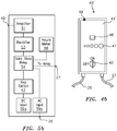
- FIG 4a illustrates an exterior view of one embodiment of the controller 40.
- the controller can include a main body 41 having a plurality of user controls and/or interface devices secured thereon. These devices can include, for example, a key switch 42, a stop button 43, a volume selector 44, an exposure time selector 45 an array indicator 46, a modulation signal strength indicator (VU meter) 47, a start button 48 and a signal input jack 49.
- VU meter modulation signal strength indicator
- FIG. 5a illustrates one embodiment of a circuitry block diagram of the controller 40 described above.
- the internal components can include, for example, a signal generator 50, an amplifier 51, one or more speakers 52, a rectifier 53, one or more solid state relays 54, a timer 56, a control switch relay 57, an hours meter 58, an AC power input device 59b, and a DC power module 59a.
- a signal generator 50 an amplifier 51
- one or more speakers 52 a rectifier 53
- one or more solid state relays 54 a timer 56
- a control switch relay 57 an hours meter 58
- an AC power input device 59b an AC power input device
- DC power module 59a DC power module
- controller 40 can be manufactured in accordance with any number of known construction methodologies, and one or more of the internal components, although listed as separate elements, can be formed together to form a printed circuit board or other such component, for example, in accordance with known manufacturing processes.
- the main body 41 can act to securely position each of the elements 42-59 in secure manner so as to form a single unit which can be operated by a user.
- the body itself can take any number of distinct shapes and sizes, and can be constructed from any number of known materials such as plastic or metal, for example. Of course, other known materials and manufacturing processes are also contemplated.
- the key switch 42 can function to provide security against operation of the device by unauthorized persons.
- the key switch can interface with a physical key and an internal relay 57 to switch the device between a plurality of operating states.
- the key can switch the device between: on with internal modulation selected, device off, and device on with external modulation source selected.
- other access control devices can also be utilized herein. Several non-limiting examples including: key fob, access code (via an integrated keypad), biometric sensors and the like.
- the stop button 43 can function to immediately cease power distribution to the array 30 when engaged.
- the speaker volume selector 44 can comprise a switch or knob, for example, which acts to control the output of the one or more speakers 52.
- the exposure time selector 45 can comprise a switch or knob, for example, which can allow a user to specify how long power will be sent to the array during a particular treatment.
- the array indicator 46 can include a light or other such notification instrument suitable for notifying a user when power is being sent to the array.
- the modulation signal strength indicator 47 can act to indicate the presence of an external modulation signal, and to display a visual representation of the signal to a user. The visual representation also indicating the delivery of power to the array 30.
- the start button 48 functions to initiate the device timer 56 and allows power to be sent to the array 30.
- One or more input jacks 49 can be provided to allow the controller 40 to interface with an external device such as a computer/tablet device, radio, television, CD player, DVD player, or MP3 player, for example. These external devices can generate and transmit an audio or sub audio input signal i.e., reference waveform such as music or words, for example, to the controller 40.
- the input jack 49 can include a standard 1/8 inch modulation input jack (e.g., mini-phone plug) and/or other forms of input devices such as a USB port, for example.
- the input jack 49 can be connected to the internal signal generator 50 such as an audio oscillator, for example, which can act to either generate or pass through the received reference waveform.
- the internal signal generator 50 such as an audio oscillator, for example, which can act to either generate or pass through the received reference waveform.
- the controller 40 can be connected to a conventional 120V AC input source, which can supply power to the internal DC module 49 for powering the controller interfaces.
- the received AC power can also be modulated and subsequently transferred to the array 30 which can utilize the same to generate an optical output.
- the controller 40 and/or array 30 can also include any number of fuses to protect the recipient, operator and device in the event of an electrical problem or excessive current flow through the device components.
- the flow of electricity (120 VAC) to the array 30 can be controlled by the timer circuit 56, which can interface with the start button 48, stop button 43, the exposure time selector 45 and the array indicator 46.
- the controller 40 can vary the fluency of the photonic energy delivered to the skin and underlying tissue.
- the start button 48 begins the timer circuit 56, which allows power to be sent to the array 30 for conversion into light via the plurality of optical emitters 32.
- the hours meter 58 advances to record the total operation time of the device.
- the controller 40 can execute a method to control the fluency by modulation of the current transmitted to the optical emitters 32 of the array 30.
- the current to the array 30 can vary based on the frequency of the reference waveform (i.e., audio input signal) that is internally generated 50 or that is generated by an external device and connected to the input jack 49.
- the reference waveform 61 (see FIG. 6a ) can be supplied to the amplifier 51 before being sent to the rectifier 53.
- the rectifier can function to produce an output voltage representing only the positive portion of the reference waveform.
- This output voltage 62 (See FIG. 6b ) can function to activate the Solid-State Relay (SSR) 54, and the negative portion is shunted to ground.
- SSR Solid-State Relay
- 120V AC power can be passed to the array 30 for conversion into light via the plurality of optical emitters 32.
- the SSR can prevent the 120V AC power from passing to the array 30 until the next positive cycle of the reference signal 61.
- modulation of the array output is accomplished by varying the current and pulse width of the 120V AC voltage supplied to the array 30 from the controller 40.
- the VU Meter 47 can be in communication with the signal generator and rectifier in order to provide a visual indicator of the input frequency strength for purposes of adjustment.
- the audio amplifier 51 can also provide the input signal to the speaker 52 so as to allow the operator to simultaneously listen to the input signal.
- Each of the amplifier and speaker can be controlled by the volume selector 44 in order to vary the volume of the monitored input signal.
- the content of the audio input signal controls the array fluency with respect to time, affecting and controlling the photonic energy delivered to the skin and underlying tissue.
- a different audio recording (or video recording with sound) will result in the array having a different fluency and excitation patterns with respect to time, which further results in varying photochemical and biochemical responses and outcomes at a cellular level.
- the controller 40 can allow an operator maximum flexibility for generating a virtually unlimited number of array fluencies through modulation of various audio input signals.
- the device 20 can be operated without modulation, wherein the controller 40 can provide a constant and steady power source to the array 30 for a specific period of time.
- FIGS. 4b, and 5b illustrate another embodiment of a controller for operating the array 30.
- controller 40' can also include a main body 41', having one or more user controls and/or interface devices secured thereon. These devices can also include a key switch 42, an array indicator 46, a modulation signal strength indicator 47, and a signal input jack 49. Of course any number of other interface devices can also be provided. As shown by the exemplary circuitry block diagram, the controller 40' can include, for example, an amplifier 51, a rectifier 53, one or more solid state relays 54, an hour meter 58, an AC power input 59b, and a DC power module 59a.
- the key switch 42 functions to replace the start button and the stop button.
- the controller 40' provides power to the array 30 based on a reference waveform received by the input jack 49, as described above.
- the key is in the off position, no power is sent to the array, and the DC power to the controller components is disabled.
- Such a feature can allow the size of the controller to be small in nature, typically between about 14 and 20 inches, so as to enable the device to be easily transported.
- FIG. 7 illustrates one embodiment of the cellulite and fat reducing device utilizing an array of optical emitters 30 to treat a recipient.
- the recipient 5 can be positioned on a table 6 or other suitable platform, and the array 30 can be positioned above the target area 1 (in this example, the buttocks) of the recipient via the stand 25.
- the array can be positioned at any desirable distance from the target area of the recipient and an operator (not shown) can utilize the controller 40 to activate the array. Once activated, the optical emitters of the array can produce the optical output 35 described above at the target wavelength, for any desirable period of time such as between 1 and 30 minutes, for example, although the preferable exposure time will be approximately 20 minutes.
- FIG 8 illustrates another embodiment of the device 20 wherein a plurality of curved arrays 30 and 30' can operate in unison to treat symmetrical target areas 1 and 1a of a recipient 5 simultaneously.
- the illustrated example shows treatment for the this of the recipient, but can easily be adjusted to treat the hips and the upper arms, for example.
- array 30' can be constructed in an essentially identical manner as array 30 described above, and each of the arrays can be tethered 27 to a single controller 40.
- a single device 20 can function to treat multiple areas of a recipient at one time.
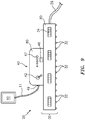
- FIG. 9 illustrates yet another embodiment of the device 20, wherein the controller 40 and array 30 are integrated into a singular structure.
- the controller main body 41 and the array main body 41 are joined to create a unified main body 90 that houses the controller and array components as heretofore described.
- the device 20 can be connected to an external device 10 (in this instance a tablet pc) via an audio cable 11 in order to receive the audio signal.
- an external device 10 in this instance a tablet pc
- the device can operate in a self-service capacity.
- the user interfaces of the controller can be accessible to a recipient at all times during treatment.
- Such a feature can allow the recipient/end user to control the physical operation of the device at all times, thereby ensuring compliance with any jurisdictional laws or regulations regarding the operation of such equipment by anyone other than the end user/recipient.
- the device will preferably be equipped with only the on/off switch, however any number of other user interfaces can also be provided.
- one or more elements of the controllers 40 and 40' and the arrays 30 and 30' can each be constructed utilizing any number of known means of attachment such as, for example, screws, glue, compression fittings and welds, among others.
- various components may be described herein as including separate individual elements, other embodiments are contemplated wherein multiple individual components are formed together as one continuous element, either through manufacturing processes, such as welding, casting, or molding, or through the use of a singular piece of material milled or machined with the aforementioned components forming identifiable sections thereof.
Landscapes
- Health & Medical Sciences (AREA)
- Biomedical Technology (AREA)
- Life Sciences & Earth Sciences (AREA)
- Engineering & Computer Science (AREA)
- Nuclear Medicine, Radiotherapy & Molecular Imaging (AREA)
- Pathology (AREA)
- Biophysics (AREA)
- Radiology & Medical Imaging (AREA)
- Animal Behavior & Ethology (AREA)
- General Health & Medical Sciences (AREA)
- Public Health (AREA)
- Veterinary Medicine (AREA)
- Radiation-Therapy Devices (AREA)
Description
- The present description relates generally to the field of body shaping, and more particularly, to a device and method for reducing the appearance of cellulite utilizing optical emitters.
- The statements in this section merely provide background information related to the present disclosure and may not constitute prior art.
- Cellulite is a condition of the body wherein persistent subcutaneous fat accumulates at specific locations to cause a noticeable dimpling of the skin. Background
FIG. 1 , illustrates a side by side comparison of the fat cell structure within women and men. As shown, owing to the differences in the structure, cellulite is most commonly found in women, and typically forms about the thighs, hips, stomach and upper arms. - Unlike other forms of fat which can be reduced through diet and exercise, cellulite and the resulting "cottage cheese" appearance of the skin do not react to these traditional methods. As a result, cellulite can be found in individuals of all body types having body mass indexes ranging from "normal" to "overweight" and "obese."
- As a result of the above, a number of approaches have been proposed to temporarily reduce the appearance of cellulite. For example, one approach may involve a user using creams such as those containing Caffeine or Aminophylline to temporarily reduce the appearance of cellulite. However, such creams are messy, with no immediate results (in fact, most see no reduction in the appearance of cellulite for 4 to 6 weeks with daily use), maintenance is difficult to achieve and even harder to maintain, and even when results are good, and the recurring costs can be quite expensive. Furthermore, many of the lotions and creams that are applied topically can require multiple applications per week, can require the use of drugs or chemicals, can be irritating to the skin and must be used consistently over time to achieve then maintain desirable results.
- In a different field of study, recent advancements in light emitting devices have seen the introduction of laser and LED systems which can target more traditional fat cells, such as those described above that are affected by diet and exercise. One such example is described in
U.S. Patent application serial number 13/782,377 , published asUS 9,498,641 - Accordingly, it would be beneficial to provide a device and method which can effectively reduce cellulite and/or the appearance of cellulite utilizing a plurality of non-invasive optical emitters, and which does not suffer from the above noted drawbacks.
GB2442206
WO2013070946 andWO2013134101 both relate to methods, devices and systems for delivering light therapy to human or non-human animal subjects. - The present description is directed to a cellulite and fat reducing device and method utilizing optical emitters. In one aspect, there is provided a device for reducing the appearance of cellulite and fat on a recipient's body, said device comprising:
- an output array that includes
- a main body having a first surface which may be oriented toward and positioned a first distance from, a target area of a recipient to be treated,
- a plurality of optical emitters disposed within the main body such that an optical emission from each of the emitters is directed outward from the first surface; and
- a controller that is in communication with the array,
- said controller including a plurality of user interface devices for instructing an
- operation of the array and for transitioning the array between an on-position and an off position,
- wherein in the on-position, the array is configured to produce an optical output of green light at approximately 529.6nm, and at approximately 48,860 Lux, said total output measurable at the first surface of the array.
- Another embodiment can include components for modulating the power delivered to the array based on a reference waveform created internally or via an external device.
Yet another embodiment of the present invention can include a cosmetic method for reducing the appearance of cellulite and fat on a recipient's body, said method comprising: - providing a device for applying optical emissions to a recipients body, said device including an output array having a plurality of optical emitters, and a controller for instructing an operation of the array;
- positioning the array between about 1 and 8 inches from a target area of the recipient;
- providing a power source to the array;
- producing, via the array, an optical output at a target wavelength;
- directing the optical output towards the target area of the recipient,
- wherein each of the plurality of optical emitters comprise, at least one of, a light emitting capacitor, a light emitting diode, and a super-luminous light emitting diode; wherein the target wavelength includes an optical output of green light at approximately 529.6nm, and at approximately 48,860 Lux.
- Presently preferred embodiments are shown in the drawings.
-
FIG. 1 is a side by side comparison of the inner structure of subcutaneous fat in both the female and male body, that is useful for understanding the inventive concepts disclosed herein. -
FIG. 2 is a perspective view of the cellulite and fat reducing device utilizing optical emitters in accordance with one embodiment. -
FIG. 3a is a bottom side view of the array for use with the cellulite and fat reducing device utilizing optical emitters in accordance with one embodiment. -
FIG. 3b is a perspective side view of the array of the cellulite and fat reducing device utilizing optical emitters in accordance with one embodiment. -
FIG. 4a is a perspective view of the controller of the cellulite and fat reducing device utilizing optical emitters in accordance with one embodiment. -
FIG. 4b is a perspective view of the controller of the cellulite and fat reducing device utilizing optical emitters in accordance with another embodiment. -
FIG. 5a is a schematic block circuit diagram of the controller of the cellulite and fat reducing device utilizing optical emitters in accordance with one embodiment. -
FIG. 5b is a schematic block circuit diagram of the controller of the cellulite and fat reducing device utilizing optical emitters in accordance with another embodiment. -
FIGS. 6a and 6b are diagrams of the modulation input signal and the rectified input signal, respectively, in the controller ofFIG. 4a . -
FIG. 7 is a perspective view of the cellulite and fat reducing device utilizing optical emitters in operation, and in accordance with one embodiment. -
FIG. 8 is a perspective view of the cellulite and fat reducing device utilizing optical emitters in operation, and in accordance with an alternate embodiment. -
FIG. 9 is a perspective view of the cellulite and fat reducing device in accordance with another alternate embodiment. - Through extensive research testing and development, the inventors have discovered that cellulite and/or the appearance of cellulite deposits can be reduced through exposure to photonic energy that is applied by optical emitters at a target wavelength and for a specific duration of time. Moreover, the inventors have also discovered that actual fat deposits can be reduced because subcutaneous adipocytes will expel their lipid content when treated with the below described system and method.
- In this regard, a cellulite and fat reducing device and method utilizing optical emitters can act to decrease the existence and/or appearance of cellulite deposits, and can also function to remove fat deposits without permanent or adverse effects on the cells and their surrounding tissues. The device can illuminate the epidermis, dermis and subcutaneous fat tissue by applying light/radiation from an array of optical emitters at a target wavelength. Such exposure functions to tighten and smooth the skin, and to reduce the size of subcutaneous fat in the exposed areas (typically the thighs and buttocks). Modulation is not required, but may enhance results.
- As described herein, the term "optical emitter" can include any form of light producing and/or emitting device having any number of different colors across the color spectrum. Several non-limiting examples can include Light Emitting Diodes (LED's), light emitting capacitors, and/or super-luminous light emitting diodes, for example, that are capable of individually and/or jointly creating optical emissions of light/radiation at a target wavelength.
- In the preferred embodiment, the below described array can utilize a plurality of green LED's. In this regard, studies have shown that exposure to green light induces a photochemical reaction within the human body that induces a biological cascade at the cellular level. This cascade promotes collagen synthesis at the location where the light is received and thus causes the skin at this location to tighten. Stated differently, the application of the green light causes structural corrections to the irregular pattern of the connective tissue associated with collagen. These effects result in an improvement in the appearance of cellulite, as measured by the Nurnberger-Muller Scale, thus reducing the appearance of the dimpling effects of cellulite. Additionally, exposure to the optical output of the array at the below described target wavelength can ultimately eliminate the underlying fat deposits causing the appearance of cellulite on the skin.
- As described herein, a "target wavelength" and an "optical output" shall be used interchangeably to describe the measurable light/radiation output of one or more optical emitters, and/or the below described array that is sufficient to apply about 383 Lux subcutaneously to the cellulite fat deposits (i.e., target area) located on a human recipient for a total delivered energy of 8.8 Joules (typically requiring an exposure duration of between 15 and 25 minutes).
- As human skin and the underlying tissue reflects and/or absorbs light, it is necessary that the measurable light/radiation output leaving the array be greater than the amount that is desired to make contact with the subcutaneous fat deposits of the recipient. In one embodiment, this measurable optical output (measurable at the array itself) shall include an output of green light at approximately 529.6nm, at approximately 48,860 Lux. When the array is positioned at a distance of between 1 and 8 inches from the skin/target area of the recipient, approximately 383 Lux (of the 48,860 produced by the array) can penetrate the skin and can be delivered to the subcutaneous fat deposits. Of course, the distance and time can be slightly adjusted to account for the inherent variances of skin makeup from one person to another. In either instance, upon receiving the 383 Lux at 529.6nm for approximately 15 to 25 minutes, the desired energy of 8.8 Joules will be delivered, thereby reducing the fat deposits which, along with the above described collagen production causes an immediate and noticeable reduction in the existence and/or appearance of cellulite at the target area.
- As is known to those of skill in the art, unlike lasers, which are monochromatic and can be manufactured to produce an identifiable and constant wavelength, LEDs have a distribution of colors. Therefore, LEDs have a spectrum distribution as opposed to a fixed wavelength that takes into account light output and color. As such, current manufacturing techniques may be unable to provide a plurality of LEDs which can each deliver an exact peak or dominant wavelength at exactly 529.6nm on a consistent basis. Therefore, when utilizing LEDs, within the below described array, the optical output can include an output spectrum approaching or as close to 529.6nm as possible so as to deliver about 383 Lux subcutaneously. Such a feature can be accomplished by individually testing the output of each LED prior to positioning the light within the array.
- Accordingly, when operating in the target wavelength i.e. at a suitable power dosimetry, e.g., from about 50mW/cm2 to about 110mW/cm2, the device can effectively reduce the existence and/or appearance of cellulite as described above.
- Turning now to the drawings, where identical reference numerals are used for like elements of the invention or elements of like function. For the sake of clarity, only those reference numerals are shown in the individual figures which are necessary for the description of the respective figure. For purposes of this description, the terms "upper," "bottom," "right," "left," "front," "vertical," "horizontal," and derivatives thereof shall relate to the device as oriented in
FIG. 2 . -
FIG. 2 illustrates one embodiment of a cellulite and fat reducing device utilizing optical emitters that is useful for understanding the inventive concepts disclosed herein. As shown, thedevice 20 can include an array of optical emitters 30 (array) which can operate to produce photonic energy in the form of light/radiation 35 at a target wavelength when instructed by acontroller 40. Amulti-positional stand 25 can be secured to thearray 30 for precise alignment and positioning over a recipient. Thecontroller 40 can include apower cable 26 for mating with a conventional 120V AC power source, and asecond cable 27 can be provided to supply power from thecontroller 40 to thearray 30. -
FIGS. 3a and 3b illustrate one embodiment of asuitable array 30. The array can include a generally rectangular main body having atop surface 31a, abottom surface 31b, afront surface 31c, aback surface 31d and opposingside surfaces optical emitters 32 are positioned within themain body 31 so as to allow the emissions therefrom to be directed outward from thebottom surface 31b. Additionally, a plurality of ventilation devices such asfans 33 heat syncs (not shown) and/orair vents 34 can be provided on or within the main body to allow proper air ventilation. - In one preferred embodiment, the main body can be constructed from metal, and the plurality of
optical emitters 32 can include 150 2-Watt green LED's that operate at 120V AC power from thecable 27, at the discretion of thecontroller 40. When power is provided to thearray 30, the plurality ofemitters 32 can produce an optical output at the target wavelength. Owing to the shape and size of the body portions most commonly afflicted with the appearance of cellulite, the array can preferably include a dimension of approximately 20 inches by 20 inches, suitable for easily directing the optical emitters to the desired target area. Moreover, the shape of the array can be curved, so as to enable the optical emitters to reach around the curved surfaces of a recipients buttocks, thighs and hips. Of course, the array is not limited to any particular shape, size and/or dimension. - Although described above as including a specific shape, size, construction material, type and number of light emitting sources, this is for illustrative purposes only, as those of skill in the art will recognize that many different combinations and types of optical emitters and/or main body shapes and construction materials can also be utilized to achieve the desired optical output described above. Moreover, although illustrated as protruding out from the main body, the
optical emitters 32 can also be flush mounted in accordance with known manufacturing techniques. -
FIG 4a illustrates an exterior view of one embodiment of thecontroller 40. As shown, the controller can include amain body 41 having a plurality of user controls and/or interface devices secured thereon. These devices can include, for example, akey switch 42, astop button 43, avolume selector 44, anexposure time selector 45 anarray indicator 46, a modulation signal strength indicator (VU meter) 47, astart button 48 and asignal input jack 49. Of course any number of other interface devices can also be provided, as necessary or desired to control the functionality of the array. -
FIG. 5a illustrates one embodiment of a circuitry block diagram of thecontroller 40 described above. As shown, the internal components can include, for example, asignal generator 50, anamplifier 51, one ormore speakers 52, arectifier 53, one or more solid state relays 54, atimer 56, acontrol switch relay 57, anhours meter 58, an ACpower input device 59b, and aDC power module 59a. Each of these components and the user interfaces described above can be communicatively linked via one or moreinternal cables 55, bus or other suitable device. The above described diagram is exemplary in nature, as any number of different and/or additional components necessary for operation of the device are also contemplated. - Although described above as including specific features, those of skill in the art will recognize that any means for controlling the operation of the array can be provided herein. To this end, the
controller 40 can be manufactured in accordance with any number of known construction methodologies, and one or more of the internal components, although listed as separate elements, can be formed together to form a printed circuit board or other such component, for example, in accordance with known manufacturing processes. - The
main body 41 can act to securely position each of the elements 42-59 in secure manner so as to form a single unit which can be operated by a user. The body itself can take any number of distinct shapes and sizes, and can be constructed from any number of known materials such as plastic or metal, for example. Of course, other known materials and manufacturing processes are also contemplated. - The
key switch 42 can function to provide security against operation of the device by unauthorized persons. To this end, the key switch can interface with a physical key and aninternal relay 57 to switch the device between a plurality of operating states. For example, the key can switch the device between: on with internal modulation selected, device off, and device on with external modulation source selected. Although illustrated herein as using a physical key, other access control devices can also be utilized herein. Several non-limiting examples including: key fob, access code (via an integrated keypad), biometric sensors and the like. - The
stop button 43 can function to immediately cease power distribution to thearray 30 when engaged. Thespeaker volume selector 44 can comprise a switch or knob, for example, which acts to control the output of the one ormore speakers 52. Theexposure time selector 45 can comprise a switch or knob, for example, which can allow a user to specify how long power will be sent to the array during a particular treatment. Thearray indicator 46 can include a light or other such notification instrument suitable for notifying a user when power is being sent to the array. - The modulation
signal strength indicator 47 can act to indicate the presence of an external modulation signal, and to display a visual representation of the signal to a user. The visual representation also indicating the delivery of power to thearray 30. Thestart button 48 functions to initiate thedevice timer 56 and allows power to be sent to thearray 30. - One or more input jacks 49 can be provided to allow the
controller 40 to interface with an external device such as a computer/tablet device, radio, television, CD player, DVD player, or MP3 player, for example. These external devices can generate and transmit an audio or sub audio input signal i.e., reference waveform such as music or words, for example, to thecontroller 40. In one preferred embodiment, theinput jack 49 can include a standard 1/8 inch modulation input jack (e.g., mini-phone plug) and/or other forms of input devices such as a USB port, for example. - The
input jack 49 can be connected to theinternal signal generator 50 such as an audio oscillator, for example, which can act to either generate or pass through the received reference waveform. - In operation, the
controller 40 can be connected to a conventional 120V AC input source, which can supply power to theinternal DC module 49 for powering the controller interfaces. The received AC power can also be modulated and subsequently transferred to thearray 30 which can utilize the same to generate an optical output. Thecontroller 40 and/orarray 30 can also include any number of fuses to protect the recipient, operator and device in the event of an electrical problem or excessive current flow through the device components. The flow of electricity (120 VAC) to thearray 30 can be controlled by thetimer circuit 56, which can interface with thestart button 48,stop button 43, theexposure time selector 45 and thearray indicator 46. - Together with array positioning relative to the client's body, the
controller 40 can vary the fluency of the photonic energy delivered to the skin and underlying tissue. Thestart button 48 begins thetimer circuit 56, which allows power to be sent to thearray 30 for conversion into light via the plurality ofoptical emitters 32. When the array is illuminated, thehours meter 58 advances to record the total operation time of the device. - The
controller 40 can execute a method to control the fluency by modulation of the current transmitted to theoptical emitters 32 of thearray 30. In one embodiment, the current to thearray 30 can vary based on the frequency of the reference waveform (i.e., audio input signal) that is internally generated 50 or that is generated by an external device and connected to theinput jack 49. - The reference waveform 61 (see
FIG. 6a ) can be supplied to theamplifier 51 before being sent to therectifier 53. The rectifier can function to produce an output voltage representing only the positive portion of the reference waveform. This output voltage 62 (SeeFIG. 6b ) can function to activate the Solid-State Relay (SSR) 54, and the negative portion is shunted to ground. As such, when the SSR is active, 120V AC power can be passed to thearray 30 for conversion into light via the plurality ofoptical emitters 32. Alternatively, when theoutput voltage 62 is not present, or drops below a predetermined threshold, the SSR can prevent the 120V AC power from passing to thearray 30 until the next positive cycle of thereference signal 61. As such, modulation of the array output is accomplished by varying the current and pulse width of the 120V AC voltage supplied to thearray 30 from thecontroller 40. - The
VU Meter 47 can be in communication with the signal generator and rectifier in order to provide a visual indicator of the input frequency strength for purposes of adjustment. Theaudio amplifier 51 can also provide the input signal to thespeaker 52 so as to allow the operator to simultaneously listen to the input signal. Each of the amplifier and speaker can be controlled by thevolume selector 44 in order to vary the volume of the monitored input signal. - The content of the audio input signal controls the array fluency with respect to time, affecting and controlling the photonic energy delivered to the skin and underlying tissue. A different audio recording (or video recording with sound) will result in the array having a different fluency and excitation patterns with respect to time, which further results in varying photochemical and biochemical responses and outcomes at a cellular level. By providing a means for communicating with an external device, the
controller 40 can allow an operator maximum flexibility for generating a virtually unlimited number of array fluencies through modulation of various audio input signals. - Although described above as including the ability to produce a modulated signal, other embodiments are also contemplated. To this end, the
device 20 can be operated without modulation, wherein thecontroller 40 can provide a constant and steady power source to thearray 30 for a specific period of time. - Although described above with respect to particular components, those of skill in the art will recognize that the inventive concepts disclosed herein can be accomplished by substituting certain components for other functionally equivalent components, or by reducing the number of components into a more simplified controller. To this end,
FIGS. 4b, and 5b , illustrate another embodiment of a controller for operating thearray 30. - As shown, controller 40' can also include a main body 41', having one or more user controls and/or interface devices secured thereon. These devices can also include a
key switch 42, anarray indicator 46, a modulationsignal strength indicator 47, and asignal input jack 49. Of course any number of other interface devices can also be provided. As shown by the exemplary circuitry block diagram, the controller 40' can include, for example, anamplifier 51, arectifier 53, one or more solid state relays 54, anhour meter 58, anAC power input 59b, and aDC power module 59a. - In the present embodiment, the
key switch 42 functions to replace the start button and the stop button. In this regard, when the key switch is in the on position, the controller 40' provides power to thearray 30 based on a reference waveform received by theinput jack 49, as described above. Conversely, when the key is in the off position, no power is sent to the array, and the DC power to the controller components is disabled. Such a feature can allow the size of the controller to be small in nature, typically between about 14 and 20 inches, so as to enable the device to be easily transported. -
FIG. 7 illustrates one embodiment of the cellulite and fat reducing device utilizing an array ofoptical emitters 30 to treat a recipient. As shown, therecipient 5 can be positioned on a table 6 or other suitable platform, and thearray 30 can be positioned above the target area 1 (in this example, the buttocks) of the recipient via thestand 25. - The array can be positioned at any desirable distance from the target area of the recipient and an operator (not shown) can utilize the
controller 40 to activate the array. Once activated, the optical emitters of the array can produce theoptical output 35 described above at the target wavelength, for any desirable period of time such as between 1 and 30 minutes, for example, although the preferable exposure time will be approximately 20 minutes. - Although described above with reference to a single controller and a single array, other embodiments are also contemplated.
FIG 8 illustrates another embodiment of thedevice 20 wherein a plurality ofcurved arrays 30 and 30' can operate in unison to treatsymmetrical target areas recipient 5 simultaneously. In this regard, the illustrated example shows treatment for the this of the recipient, but can easily be adjusted to treat the hips and the upper arms, for example. - As described herein array 30' can be constructed in an essentially identical manner as
array 30 described above, and each of the arrays can be tethered 27 to asingle controller 40. In this regard, asingle device 20 can function to treat multiple areas of a recipient at one time. -
FIG. 9 illustrates yet another embodiment of thedevice 20, wherein thecontroller 40 andarray 30 are integrated into a singular structure. In the present embodiment, the controllermain body 41 and the arraymain body 41 are joined to create a unified main body 90 that houses the controller and array components as heretofore described. As shown, thedevice 20 can be connected to an external device 10 (in this instance a tablet pc) via anaudio cable 11 in order to receive the audio signal. - By providing a more simplified array and controller, as described above, the device can operate in a self-service capacity. To this end, the user interfaces of the controller can be accessible to a recipient at all times during treatment. Such a feature can allow the recipient/end user to control the physical operation of the device at all times, thereby ensuring compliance with any jurisdictional laws or regulations regarding the operation of such equipment by anyone other than the end user/recipient. In this regard, the device will preferably be equipped with only the on/off switch, however any number of other user interfaces can also be provided.
- As described herein, one or more elements of the
controllers 40 and 40' and thearrays 30 and 30' can each be constructed utilizing any number of known means of attachment such as, for example, screws, glue, compression fittings and welds, among others. Moreover, although various components may be described herein as including separate individual elements, other embodiments are contemplated wherein multiple individual components are formed together as one continuous element, either through manufacturing processes, such as welding, casting, or molding, or through the use of a singular piece of material milled or machined with the aforementioned components forming identifiable sections thereof. - As to a further description of the manner and use of the present invention, the same should be apparent from the above description. Accordingly, no further discussion relating to the manner of usage and operation will be provided. For completeness, 1 inch = 2,54 cm.
- The present invention is set out in the appended claims. The embodiments, aspects or examples according to the present description that do not fall within the scope of said claims are provided for illustrative purposes only and do not form part of the present invention.
Claims (15)
- A device (20) for reducing the appearance of cellulite and fat on a recipient's body, said device (20) comprising:an output array (30) that includesa main body (31) having a first surface (31b) which may be oriented toward and positioned a first distance from, a target area of a recipient to be treated,a plurality of optical emitters (32) disposed within the main body (31) such that an optical emission from each of the emitters (32) is directed outward from the first surface (31b); anda controller (40) that is in communication with the array (30),said controller including a plurality of user interface devices for instructing an operation of the array (30) and for transitioning the array (30) between an on-position and an off position,wherein in the on-position, the array (30) is configured to produce an optical output of green light at approximately 529.6nm, and at approximately 48,860 Lux, said total output measurable at the first surface (31b) of the array (30).
- The device (20) of claim 1, wherein each of the plurality of optical emitters (32) comprise, at least one of, a light emitting capacitor, a light emitting diode, and a superluminous light emitting diode;
or wherein the plurality of optical emitters (32) include 150 2-Watt LEDs having an output spectrum of approximately 529.6nm. - The device (20) of claim 1, wherein the controller (40) further includes a key switch access control device (42), an input jack (49) for receiving a reference waveform from an external device, a power input module (59b), a rectifier (53) and a solid state relay (54), said rectifier and relay functioning to provide a modulated power output to the array (30) based on the received reference waveform;
or wherein the controller (40) further includes a key switch access control (42), an internal signal generator (50) for creating a reference waveform, a power input module (59b), a rectifier (53) and a solid state relay (54), said rectifier and relay functioning to provide a modulated power output to the array (30) based on the created reference waveform. - The device (20) of claim 3, wherein the rectifier (53) and relay (54) function to provide the power output to the array (30) only during a positive portion of the received reference waveform.
- The device (20) of claim 1, wherein the controller (40) is integrated into the main Body (31) of the output array (30).
- The device (20) of claim 5, wherein the user interface devices of the controller (40) are positioned to allow a recipient to operate the device (20) in a self-service capacity.
- The device (20) of claim 1, wherein the first distance is between 1 and 8 inches, and in the on-position, the array (30) produces green light at approximately 529.6nm and at about 383 Lux measurable at a subcutaneous location of the target area of the recipient; or wherein the target area includes a dimension of about 12 inches by 12 inches measurable on the recipient.
- The device (20) of claim 1, further comprising:a second output array that is also in communication with the controller (40),said second array including a first surface which may be oriented toward a second target area of the recipient to be treated, and producing an optical output of green light at approximately 529.6nm, and at approximately 48,860 Lux.
- The device (20) of claim 1wherein the output array (30) further comprises:an input jack (49) for receiving a reference waveform from an external device, a power input module (59b),a rectifier (53), anda solid state relay (54), said rectifier (53) and relay (54) functioning to provide a modulated power output to the array (30) based on the received reference waveform.
- The device (20) of claim 9, wherein the optical output of the array (30) is produced only during a positive portion of the received reference waveform.
- A cosmetic method for reducing the appearance of cellulite and fat on a recipient's body, said method comprising:providing a device (20) for applying optical emissions to a recipients body, said device including an output array (30) having a plurality of optical emitters (32), and a controller (40) for instructing an operation of the array (30);positioning the array (30) between about 2,5 cm and 20,3 cm ( 1 and 8 inches) from a target area of the recipient;providing a power source to the array (30);producing, via the array (30), an optical output at a target wavelength;directing the optical output towards the target area of the recipient,wherein each of the plurality of optical emitters (32) comprise, at least one of, a light emitting capacitor, a light emitting diode, and a super-luminous light emitting diode; wherein the target wavelength includes an
optical output of green light at approximately 529.6nm, and at approximately 48,860 Lux. - The method of claim 11, further comprising:delivering the green light at approximately 383 Lux at a wavelength ofapproximately 529.6nm for between 15 and 25 minutes, resulting in a total delivery of 8.8 Joules to an accumulated subcutaneous fat deposit within the target area of the recipient.
- The method of claim 11, further comprising:
modulating the power source before providing the same to the array (30). - The method of claim 13, wherein said modulation is based on a reference waveform generated by the controller (40).
- The method of claim 11, further comprising:
receiving a reference waveform from an external device; and modulating, the power source based on the received waveform before providing the same to the array (30).
Applications Claiming Priority (2)
| Application Number | Priority Date | Filing Date | Title |
|---|---|---|---|
| US201361900809P | 2013-11-06 | 2013-11-06 | |
| PCT/US2014/063833 WO2015069629A1 (en) | 2013-11-06 | 2014-11-04 | Cellulite and fat reducing device and method utilizing optical emitters |
Publications (3)
| Publication Number | Publication Date |
|---|---|
| EP3065823A1 EP3065823A1 (en) | 2016-09-14 |
| EP3065823A4 EP3065823A4 (en) | 2017-06-07 |
| EP3065823B1 true EP3065823B1 (en) | 2020-09-09 |
Family
ID=53007586
Family Applications (1)
| Application Number | Title | Priority Date | Filing Date |
|---|---|---|---|
| EP14860875.5A Active EP3065823B1 (en) | 2013-11-06 | 2014-11-04 | Cellulite and fat reducing device and method utilizing optical emitters |
Country Status (3)
| Country | Link |
|---|---|
| US (2) | US10946210B2 (en) |
| EP (1) | EP3065823B1 (en) |
| WO (1) | WO2015069629A1 (en) |
Families Citing this family (31)
| Publication number | Priority date | Publication date | Assignee | Title |
|---|---|---|---|---|
| DE102012013534B3 (en) | 2012-07-05 | 2013-09-19 | Tobias Sokolowski | Apparatus for repetitive nerve stimulation for the degradation of adipose tissue by means of inductive magnetic fields |
| US11491342B2 (en) | 2015-07-01 | 2022-11-08 | Btl Medical Solutions A.S. | Magnetic stimulation methods and devices for therapeutic treatments |
| US10478634B2 (en) | 2015-07-01 | 2019-11-19 | Btl Medical Technologies S.R.O. | Aesthetic method of biological structure treatment by magnetic field |
| US10709894B2 (en) | 2015-07-01 | 2020-07-14 | Btl Medical Technologies S.R.O. | Aesthetic method of biological structure treatment by magnetic field |
| US10821295B1 (en) | 2015-07-01 | 2020-11-03 | Btl Medical Technologies S.R.O. | Aesthetic method of biological structure treatment by magnetic field |
| US10695575B1 (en) | 2016-05-10 | 2020-06-30 | Btl Medical Technologies S.R.O. | Aesthetic method of biological structure treatment by magnetic field |
| US10569094B2 (en) | 2015-07-01 | 2020-02-25 | Btl Medical Technologies S.R.O. | Aesthetic method of biological structure treatment by magnetic field |
| US10695576B2 (en) | 2015-07-01 | 2020-06-30 | Btl Medical Technologies S.R.O. | Aesthetic method of biological structure treatment by magnetic field |
| US11266850B2 (en) | 2015-07-01 | 2022-03-08 | Btl Healthcare Technologies A.S. | High power time varying magnetic field therapy |
| US10569095B1 (en) | 2015-07-01 | 2020-02-25 | Btl Medical Technologies S.R.O. | Aesthetic method of biological structure treatment by magnetic field |
| US20180001107A1 (en) | 2016-07-01 | 2018-01-04 | Btl Holdings Limited | Aesthetic method of biological structure treatment by magnetic field |
| US11253717B2 (en) | 2015-10-29 | 2022-02-22 | Btl Healthcare Technologies A.S. | Aesthetic method of biological structure treatment by magnetic field |
| US11247039B2 (en) | 2016-05-03 | 2022-02-15 | Btl Healthcare Technologies A.S. | Device including RF source of energy and vacuum system |
| US11464993B2 (en) | 2016-05-03 | 2022-10-11 | Btl Healthcare Technologies A.S. | Device including RF source of energy and vacuum system |
| US11534619B2 (en) | 2016-05-10 | 2022-12-27 | Btl Medical Solutions A.S. | Aesthetic method of biological structure treatment by magnetic field |
| US12654023B2 (en) | 2016-05-10 | 2026-06-16 | Btl Medical Solutions A.S. | Aesthetic method of biological structure treatment by magnetic field |
| US10583287B2 (en) | 2016-05-23 | 2020-03-10 | Btl Medical Technologies S.R.O. | Systems and methods for tissue treatment |
| US10556122B1 (en) | 2016-07-01 | 2020-02-11 | Btl Medical Technologies S.R.O. | Aesthetic method of biological structure treatment by magnetic field |
| US11141219B1 (en) | 2016-08-16 | 2021-10-12 | BTL Healthcare Technologies, a.s. | Self-operating belt |
| MX2019004642A (en) * | 2016-10-28 | 2019-09-18 | Ward Terry | Fat reducing device and method utilizing optical emitters. |
| US11517373B2 (en) * | 2016-12-27 | 2022-12-06 | Alma Lasers Ltd. | Switched lasers for dermal treatment |
| EP4691400A3 (en) | 2019-04-11 | 2026-04-22 | BTL Medical Solutions a.s. | Methods and devices for treatment of biological structure by radiofrequency energy |
| US12558146B2 (en) | 2019-04-11 | 2026-02-24 | Btl Medical Solutions A.S. | Methods and devices for aesthetic treatment of biological structures by radiofrequency and magnetic energy |
| US12156689B2 (en) | 2019-04-11 | 2024-12-03 | Btl Medical Solutions A.S. | Methods and devices for aesthetic treatment of biological structures by radiofrequency and magnetic energy |
| HRP20250160T1 (en) | 2020-05-04 | 2025-03-28 | Btl Healthcare Technologies A.S. | DEVICE FOR TREATING PATIENTS WITHOUT THE PRESENCE OF A DOCTOR |
| US12611545B2 (en) | 2020-05-04 | 2026-04-28 | Btl Healthcare Technologies A.S. | Device and method for unattended treatment of a patient |
| US11878167B2 (en) | 2020-05-04 | 2024-01-23 | Btl Healthcare Technologies A.S. | Device and method for unattended treatment of a patient |
| CA3260012A1 (en) | 2021-10-13 | 2023-04-20 | Btl Medical Solutions A.S. | Devices for aesthetic treatment of biological structures by radiofrequency and magnetic energy |
| US11896816B2 (en) | 2021-11-03 | 2024-02-13 | Btl Healthcare Technologies A.S. | Device and method for unattended treatment of a patient |
| IT202100029783A1 (en) * | 2021-11-25 | 2023-05-25 | Loris Persello | EQUIPMENT FOR BEAUTY AND WELL-BEING AND RELATED PROCEDURE FOR USE |
| US20260097226A1 (en) | 2024-10-08 | 2026-04-09 | Btl Medical Solutions A.S. | Devices and methods for application of a magnetic field to the nervous system |
Family Cites Families (30)
| Publication number | Priority date | Publication date | Assignee | Title |
|---|---|---|---|---|
| US5143063A (en) | 1988-02-09 | 1992-09-01 | Fellner Donald G | Method of removing adipose tissue from the body |
| US5507790A (en) | 1994-03-21 | 1996-04-16 | Weiss; William V. | Method of non-invasive reduction of human site-specific subcutaneous fat tissue deposits by accelerated lipolysis metabolism |
| US6135117A (en) * | 1997-05-12 | 2000-10-24 | Cornell Research Foundation, Inc. | Non-ocular circadian clock resetting in humans |
| US20060212025A1 (en) * | 1998-11-30 | 2006-09-21 | Light Bioscience, Llc | Method and apparatus for acne treatment |
| CA2317319A1 (en) * | 2000-03-14 | 2001-09-14 | The Litebook Company Ltd | Light therapy device |
| US6602275B1 (en) * | 2000-09-18 | 2003-08-05 | Jana Sullivan | Device and method for therapeutic treatment of living organisms |
| US6645162B2 (en) | 2000-12-27 | 2003-11-11 | Insightec - Txsonics Ltd. | Systems and methods for ultrasound assisted lipolysis |
| US20070239143A1 (en) * | 2006-03-10 | 2007-10-11 | Palomar Medical Technologies, Inc. | Photocosmetic device |
| WO2004000150A1 (en) | 2002-06-19 | 2003-12-31 | Palomar Medical Technologies, Inc. | Method and apparatus for photothermal treatment of tissue at depth |
| US20080091250A1 (en) * | 2002-09-26 | 2008-04-17 | Lumiport, Llc | Light therapy desk lamp |
| US7993382B2 (en) | 2004-02-06 | 2011-08-09 | Erchonia Corporation | Fat reduction using external laser radiation and niacin |
| US8813756B1 (en) * | 2004-02-06 | 2014-08-26 | Erchonia Corporation | Non-invasive method for slimming a human body using laser energy of wavelengths shorter than 632 nm |
| JP2007520285A (en) * | 2004-02-06 | 2007-07-26 | バロレ,ダニエル | Method and apparatus for treating mammalian tissue |
| US20060064144A1 (en) * | 2004-06-25 | 2006-03-23 | Chen Joshua Q | Programmable multifunction table lamp for light therapy |
| US20070031482A1 (en) * | 2005-08-02 | 2007-02-08 | Ceramoptec Industries, Ind. | PDT treatment method for cellulites and cosmetic use |
| AU2007208264A1 (en) | 2006-01-24 | 2007-08-02 | Nomir Medical Technologies, Inc. | Optical method and device for modulation of biochemical processes in adipose tissue |
| CA2535276A1 (en) * | 2006-02-06 | 2007-08-06 | John Kennedy | Therapy device and system and method for reducing harmful exposure to electromagnetic radiation |
| GB2442206A (en) * | 2006-09-30 | 2008-04-02 | Aqua Detox International Ltd | Therapeutic light apparatus |
| EP2142125B1 (en) * | 2007-04-19 | 2014-03-05 | Miramar Labs, Inc. | Devices, and systems for non-invasive delivery of microwave therapy |
| US20080275533A1 (en) * | 2007-05-04 | 2008-11-06 | Powell Steven D | Display apparatus for providing information and therapeutic light |
| US20090075557A1 (en) * | 2007-09-13 | 2009-03-19 | Martin Arriola | Toy Illumination with Music |
| US9204518B2 (en) * | 2008-10-30 | 2015-12-01 | The Invention Science Fund I Llc | LED-based secondary general illumination lighting color slaved to alternate general illumination lighting |
| US8366756B2 (en) | 2009-08-28 | 2013-02-05 | Erchonia Corporation | Low level laser therapy device with open bore |
| US8435273B2 (en) * | 2010-07-21 | 2013-05-07 | Myk Wayne Lum | High powered light emitting diode photobiology device |
| US8614632B1 (en) * | 2010-11-02 | 2013-12-24 | Kenneth A Wells | Method of and apparatus for controlling a source of light in accordance in a source of sound |
| WO2013070946A2 (en) * | 2011-11-08 | 2013-05-16 | Biophotas, Inc. | Shapeable light therapy device and method |
| TW201331520A (en) * | 2012-01-19 | 2013-08-01 | Forward Electronics Co Ltd | Photostimulation method and device with light mixture |
| US20140052222A1 (en) * | 2012-08-20 | 2014-02-20 | Michael K. Thomas | Light Therapy Device and Method for Use |
| US20140067024A1 (en) * | 2012-08-30 | 2014-03-06 | Photocure Asa | Dual panel photodynamic therapy lamp |
| US9212814B2 (en) * | 2013-06-19 | 2015-12-15 | Daniel C. Puljan | Bathmats with advanced features |
-
2014
- 2014-11-04 WO PCT/US2014/063833 patent/WO2015069629A1/en not_active Ceased
- 2014-11-04 EP EP14860875.5A patent/EP3065823B1/en active Active
- 2014-11-04 US US14/532,583 patent/US10946210B2/en active Active
-
2021
- 2021-02-09 US US17/171,784 patent/US20210162231A1/en active Pending
Non-Patent Citations (1)
| Title |
|---|
| None * |
Also Published As
| Publication number | Publication date |
|---|---|
| WO2015069629A1 (en) | 2015-05-14 |
| US20150127075A1 (en) | 2015-05-07 |
| EP3065823A1 (en) | 2016-09-14 |
| EP3065823A4 (en) | 2017-06-07 |
| US10946210B2 (en) | 2021-03-16 |
| US20210162231A1 (en) | 2021-06-03 |
Similar Documents
| Publication | Publication Date | Title |
|---|---|---|
| US20210162231A1 (en) | Cellulite and fat reducing device and method utilizing optical emitters | |
| KR101444940B1 (en) | Portable type multiple function skin care device | |
| US7204846B2 (en) | Beauty device | |
| JP3218105U (en) | Three-dimensional negative pressure compound stimulator module for skin function improvement to which customized compound stimulation is applied | |
| US9808314B2 (en) | Fat reducing device and method utilizing optical emitters | |
| TWI589316B (en) | Light and ultrasonic transducer device, kit comprising light and ultrasonic transducer device, and system for delivering one or both of light and ultrasound across a skin surface | |
| US9968799B2 (en) | Shapeable light therapy device and method | |
| US20080065176A1 (en) | Vacuum and negative ions assisted phototheraphy device | |
| JP6630429B2 (en) | Skin beauty equipment | |
| CN219208739U (en) | Device for the unattended treatment of a patient | |
| JP2007020593A (en) | Beauty appliance | |
| EP3471826B1 (en) | Devices and methods to remove hair | |
| KR101479576B1 (en) | Color light therapy drive built-in smart communication device | |
| WO2018127921A1 (en) | Apparatus and method for skin rejuvenation | |
| KR20130095420A (en) | Cosmetic Container with Near Infrared Massager | |
| CN102488960B (en) | Multifunctional cosmetology instrument | |
| KR101562637B1 (en) | lipolysis apparatus using light | |
| US10967197B2 (en) | Phototherapy devices and methods for treating truncal acne and scars | |
| EP3531947A1 (en) | Fat reducing device and method utilizing optical emitters | |
| EP4596035A1 (en) | Lighting to provide photobiomodulation | |
| US20120109114A1 (en) | Hair removal by photothermolysis | |
| WO2012152234A1 (en) | Device for planar pulsed magneto-light therapy of acne | |
| KR20130095419A (en) | Cosmetic container with light irradiator | |
| BR112019008187B1 (en) | Cosmetic method for reducing the lipid content of subcutaneous adipocytes. | |
| KR200292054Y1 (en) | remedial equipment for using EL |
Legal Events
| Date | Code | Title | Description |
|---|---|---|---|
| PUAI | Public reference made under article 153(3) epc to a published international application that has entered the european phase |
Free format text: ORIGINAL CODE: 0009012 |
|
| 17P | Request for examination filed |
Effective date: 20160603 |
|
| AK | Designated contracting states |
Kind code of ref document: A1 Designated state(s): AL AT BE BG CH CY CZ DE DK EE ES FI FR GB GR HR HU IE IS IT LI LT LU LV MC MK MT NL NO PL PT RO RS SE SI SK SM TR |
|
| AX | Request for extension of the european patent |
Extension state: BA ME |
|
| DAX | Request for extension of the european patent (deleted) | ||
| A4 | Supplementary search report drawn up and despatched |
Effective date: 20170511 |
|
| RIC1 | Information provided on ipc code assigned before grant |
Ipc: A61N 5/06 20060101AFI20170504BHEP |
|
| GRAP | Despatch of communication of intention to grant a patent |
Free format text: ORIGINAL CODE: EPIDOSNIGR1 |
|
| STAA | Information on the status of an ep patent application or granted ep patent |
Free format text: STATUS: GRANT OF PATENT IS INTENDED |
|
| INTG | Intention to grant announced |
Effective date: 20200320 |
|
| GRAS | Grant fee paid |
Free format text: ORIGINAL CODE: EPIDOSNIGR3 |
|
| GRAA | (expected) grant |
Free format text: ORIGINAL CODE: 0009210 |
|
| STAA | Information on the status of an ep patent application or granted ep patent |
Free format text: STATUS: THE PATENT HAS BEEN GRANTED |
|
| AK | Designated contracting states |
Kind code of ref document: B1 Designated state(s): AL AT BE BG CH CY CZ DE DK EE ES FI FR GB GR HR HU IE IS IT LI LT LU LV MC MK MT NL NO PL PT RO RS SE SI SK SM TR |
|
| REG | Reference to a national code |
Ref country code: GB Ref legal event code: FG4D |
|
| REG | Reference to a national code |
Ref country code: AT Ref legal event code: REF Ref document number: 1310801 Country of ref document: AT Kind code of ref document: T Effective date: 20200915 Ref country code: CH Ref legal event code: EP |
|
| REG | Reference to a national code |
Ref country code: DE Ref legal event code: R096 Ref document number: 602014070094 Country of ref document: DE |
|
| REG | Reference to a national code |
Ref country code: IE Ref legal event code: FG4D |
|
| REG | Reference to a national code |
Ref country code: LT Ref legal event code: MG4D |
|
| PG25 | Lapsed in a contracting state [announced via postgrant information from national office to epo] |
Ref country code: BG Free format text: LAPSE BECAUSE OF FAILURE TO SUBMIT A TRANSLATION OF THE DESCRIPTION OR TO PAY THE FEE WITHIN THE PRESCRIBED TIME-LIMIT Effective date: 20201209 Ref country code: GR Free format text: LAPSE BECAUSE OF FAILURE TO SUBMIT A TRANSLATION OF THE DESCRIPTION OR TO PAY THE FEE WITHIN THE PRESCRIBED TIME-LIMIT Effective date: 20201210 Ref country code: LT Free format text: LAPSE BECAUSE OF FAILURE TO SUBMIT A TRANSLATION OF THE DESCRIPTION OR TO PAY THE FEE WITHIN THE PRESCRIBED TIME-LIMIT Effective date: 20200909 Ref country code: HR Free format text: LAPSE BECAUSE OF FAILURE TO SUBMIT A TRANSLATION OF THE DESCRIPTION OR TO PAY THE FEE WITHIN THE PRESCRIBED TIME-LIMIT Effective date: 20200909 Ref country code: SE Free format text: LAPSE BECAUSE OF FAILURE TO SUBMIT A TRANSLATION OF THE DESCRIPTION OR TO PAY THE FEE WITHIN THE PRESCRIBED TIME-LIMIT Effective date: 20200909 Ref country code: NO Free format text: LAPSE BECAUSE OF FAILURE TO SUBMIT A TRANSLATION OF THE DESCRIPTION OR TO PAY THE FEE WITHIN THE PRESCRIBED TIME-LIMIT Effective date: 20201209 Ref country code: FI Free format text: LAPSE BECAUSE OF FAILURE TO SUBMIT A TRANSLATION OF THE DESCRIPTION OR TO PAY THE FEE WITHIN THE PRESCRIBED TIME-LIMIT Effective date: 20200909 |
|
| REG | Reference to a national code |
Ref country code: AT Ref legal event code: MK05 Ref document number: 1310801 Country of ref document: AT Kind code of ref document: T Effective date: 20200909 |
|
| REG | Reference to a national code |
Ref country code: NL Ref legal event code: MP Effective date: 20200909 |
|
| PG25 | Lapsed in a contracting state [announced via postgrant information from national office to epo] |
Ref country code: RS Free format text: LAPSE BECAUSE OF FAILURE TO SUBMIT A TRANSLATION OF THE DESCRIPTION OR TO PAY THE FEE WITHIN THE PRESCRIBED TIME-LIMIT Effective date: 20200909 Ref country code: LV Free format text: LAPSE BECAUSE OF FAILURE TO SUBMIT A TRANSLATION OF THE DESCRIPTION OR TO PAY THE FEE WITHIN THE PRESCRIBED TIME-LIMIT Effective date: 20200909 Ref country code: PL Free format text: LAPSE BECAUSE OF FAILURE TO SUBMIT A TRANSLATION OF THE DESCRIPTION OR TO PAY THE FEE WITHIN THE PRESCRIBED TIME-LIMIT Effective date: 20200909 |
|
| PG25 | Lapsed in a contracting state [announced via postgrant information from national office to epo] |
Ref country code: CZ Free format text: LAPSE BECAUSE OF FAILURE TO SUBMIT A TRANSLATION OF THE DESCRIPTION OR TO PAY THE FEE WITHIN THE PRESCRIBED TIME-LIMIT Effective date: 20200909 Ref country code: NL Free format text: LAPSE BECAUSE OF FAILURE TO SUBMIT A TRANSLATION OF THE DESCRIPTION OR TO PAY THE FEE WITHIN THE PRESCRIBED TIME-LIMIT Effective date: 20200909 Ref country code: PT Free format text: LAPSE BECAUSE OF FAILURE TO SUBMIT A TRANSLATION OF THE DESCRIPTION OR TO PAY THE FEE WITHIN THE PRESCRIBED TIME-LIMIT Effective date: 20210111 Ref country code: EE Free format text: LAPSE BECAUSE OF FAILURE TO SUBMIT A TRANSLATION OF THE DESCRIPTION OR TO PAY THE FEE WITHIN THE PRESCRIBED TIME-LIMIT Effective date: 20200909 Ref country code: RO Free format text: LAPSE BECAUSE OF FAILURE TO SUBMIT A TRANSLATION OF THE DESCRIPTION OR TO PAY THE FEE WITHIN THE PRESCRIBED TIME-LIMIT Effective date: 20200909 Ref country code: SM Free format text: LAPSE BECAUSE OF FAILURE TO SUBMIT A TRANSLATION OF THE DESCRIPTION OR TO PAY THE FEE WITHIN THE PRESCRIBED TIME-LIMIT Effective date: 20200909 |
|
| PG25 | Lapsed in a contracting state [announced via postgrant information from national office to epo] |
Ref country code: ES Free format text: LAPSE BECAUSE OF FAILURE TO SUBMIT A TRANSLATION OF THE DESCRIPTION OR TO PAY THE FEE WITHIN THE PRESCRIBED TIME-LIMIT Effective date: 20200909 Ref country code: AT Free format text: LAPSE BECAUSE OF FAILURE TO SUBMIT A TRANSLATION OF THE DESCRIPTION OR TO PAY THE FEE WITHIN THE PRESCRIBED TIME-LIMIT Effective date: 20200909 Ref country code: AL Free format text: LAPSE BECAUSE OF FAILURE TO SUBMIT A TRANSLATION OF THE DESCRIPTION OR TO PAY THE FEE WITHIN THE PRESCRIBED TIME-LIMIT Effective date: 20200909 Ref country code: IS Free format text: LAPSE BECAUSE OF FAILURE TO SUBMIT A TRANSLATION OF THE DESCRIPTION OR TO PAY THE FEE WITHIN THE PRESCRIBED TIME-LIMIT Effective date: 20210109 |
|
| REG | Reference to a national code |
Ref country code: DE Ref legal event code: R097 Ref document number: 602014070094 Country of ref document: DE |
|
| PG25 | Lapsed in a contracting state [announced via postgrant information from national office to epo] |
Ref country code: MC Free format text: LAPSE BECAUSE OF FAILURE TO SUBMIT A TRANSLATION OF THE DESCRIPTION OR TO PAY THE FEE WITHIN THE PRESCRIBED TIME-LIMIT Effective date: 20200909 Ref country code: SK Free format text: LAPSE BECAUSE OF FAILURE TO SUBMIT A TRANSLATION OF THE DESCRIPTION OR TO PAY THE FEE WITHIN THE PRESCRIBED TIME-LIMIT Effective date: 20200909 |
|
| REG | Reference to a national code |
Ref country code: CH Ref legal event code: PL |
|
| PLBE | No opposition filed within time limit |
Free format text: ORIGINAL CODE: 0009261 |
|
| STAA | Information on the status of an ep patent application or granted ep patent |
Free format text: STATUS: NO OPPOSITION FILED WITHIN TIME LIMIT |
|
| PG25 | Lapsed in a contracting state [announced via postgrant information from national office to epo] |
Ref country code: LU Free format text: LAPSE BECAUSE OF NON-PAYMENT OF DUE FEES Effective date: 20201104 |
|
| REG | Reference to a national code |
Ref country code: BE Ref legal event code: MM Effective date: 20201130 |
|
| 26N | No opposition filed |
Effective date: 20210610 |
|
| PG25 | Lapsed in a contracting state [announced via postgrant information from national office to epo] |
Ref country code: SI Free format text: LAPSE BECAUSE OF FAILURE TO SUBMIT A TRANSLATION OF THE DESCRIPTION OR TO PAY THE FEE WITHIN THE PRESCRIBED TIME-LIMIT Effective date: 20200909 Ref country code: LI Free format text: LAPSE BECAUSE OF NON-PAYMENT OF DUE FEES Effective date: 20201130 Ref country code: CH Free format text: LAPSE BECAUSE OF NON-PAYMENT OF DUE FEES Effective date: 20201130 Ref country code: DK Free format text: LAPSE BECAUSE OF FAILURE TO SUBMIT A TRANSLATION OF THE DESCRIPTION OR TO PAY THE FEE WITHIN THE PRESCRIBED TIME-LIMIT Effective date: 20200909 |
|
| PG25 | Lapsed in a contracting state [announced via postgrant information from national office to epo] |
Ref country code: IE Free format text: LAPSE BECAUSE OF NON-PAYMENT OF DUE FEES Effective date: 20201104 |
|
| PG25 | Lapsed in a contracting state [announced via postgrant information from national office to epo] |
Ref country code: TR Free format text: LAPSE BECAUSE OF FAILURE TO SUBMIT A TRANSLATION OF THE DESCRIPTION OR TO PAY THE FEE WITHIN THE PRESCRIBED TIME-LIMIT Effective date: 20200909 Ref country code: MT Free format text: LAPSE BECAUSE OF FAILURE TO SUBMIT A TRANSLATION OF THE DESCRIPTION OR TO PAY THE FEE WITHIN THE PRESCRIBED TIME-LIMIT Effective date: 20200909 Ref country code: CY Free format text: LAPSE BECAUSE OF FAILURE TO SUBMIT A TRANSLATION OF THE DESCRIPTION OR TO PAY THE FEE WITHIN THE PRESCRIBED TIME-LIMIT Effective date: 20200909 |
|
| PG25 | Lapsed in a contracting state [announced via postgrant information from national office to epo] |
Ref country code: MK Free format text: LAPSE BECAUSE OF FAILURE TO SUBMIT A TRANSLATION OF THE DESCRIPTION OR TO PAY THE FEE WITHIN THE PRESCRIBED TIME-LIMIT Effective date: 20200909 |
|
| PG25 | Lapsed in a contracting state [announced via postgrant information from national office to epo] |
Ref country code: BE Free format text: LAPSE BECAUSE OF NON-PAYMENT OF DUE FEES Effective date: 20201130 |
|
| PGFP | Annual fee paid to national office [announced via postgrant information from national office to epo] |
Ref country code: DE Payment date: 20251114 Year of fee payment: 12 |
|
| PGFP | Annual fee paid to national office [announced via postgrant information from national office to epo] |
Ref country code: GB Payment date: 20251106 Year of fee payment: 12 |
|
| PGFP | Annual fee paid to national office [announced via postgrant information from national office to epo] |
Ref country code: IT Payment date: 20251111 Year of fee payment: 12 |
|
| PGFP | Annual fee paid to national office [announced via postgrant information from national office to epo] |
Ref country code: FR Payment date: 20251106 Year of fee payment: 12 |