EP3065157A1 - Circuit breaker assembly including a circuit breaker connector member - Google Patents
Circuit breaker assembly including a circuit breaker connector member Download PDFInfo
- Publication number
- EP3065157A1 EP3065157A1 EP16158521.1A EP16158521A EP3065157A1 EP 3065157 A1 EP3065157 A1 EP 3065157A1 EP 16158521 A EP16158521 A EP 16158521A EP 3065157 A1 EP3065157 A1 EP 3065157A1
- Authority
- EP
- European Patent Office
- Prior art keywords
- circuit breaker
- connector
- housing
- cassette
- cassettes
- Prior art date
- Legal status (The legal status is an assumption and is not a legal conclusion. Google has not performed a legal analysis and makes no representation as to the accuracy of the status listed.)
- Granted
Links
- 238000000034 method Methods 0.000 claims description 10
- 239000007789 gas Substances 0.000 claims description 9
- 230000005611 electricity Effects 0.000 claims description 7
- 239000004020 conductor Substances 0.000 description 8
- 230000007246 mechanism Effects 0.000 description 6
- 230000004913 activation Effects 0.000 description 3
- 238000004519 manufacturing process Methods 0.000 description 3
- 239000011449 brick Substances 0.000 description 2
- 230000004075 alteration Effects 0.000 description 1
- 230000009977 dual effect Effects 0.000 description 1
- 239000012799 electrically-conductive coating Substances 0.000 description 1
- 239000000463 material Substances 0.000 description 1
- 230000037361 pathway Effects 0.000 description 1
- 230000036316 preload Effects 0.000 description 1
- 230000008569 process Effects 0.000 description 1
- 230000004044 response Effects 0.000 description 1
- 238000006467 substitution reaction Methods 0.000 description 1
Images


Classifications
-
- H—ELECTRICITY
- H01—ELECTRIC ELEMENTS
- H01H—ELECTRIC SWITCHES; RELAYS; SELECTORS; EMERGENCY PROTECTIVE DEVICES
- H01H71/00—Details of the protective switches or relays covered by groups H01H73/00 - H01H83/00
- H01H71/02—Housings; Casings; Bases; Mountings
- H01H71/0264—Mountings or coverplates for complete assembled circuit breakers, e.g. snap mounting in panel
-
- H—ELECTRICITY
- H01—ELECTRIC ELEMENTS
- H01H—ELECTRIC SWITCHES; RELAYS; SELECTORS; EMERGENCY PROTECTIVE DEVICES
- H01H71/00—Details of the protective switches or relays covered by groups H01H73/00 - H01H83/00
- H01H71/02—Housings; Casings; Bases; Mountings
- H01H71/025—Constructional details of housings or casings not concerning the mounting or assembly of the different internal parts
-
- H—ELECTRICITY
- H01—ELECTRIC ELEMENTS
- H01H—ELECTRIC SWITCHES; RELAYS; SELECTORS; EMERGENCY PROTECTIVE DEVICES
- H01H69/00—Apparatus or processes for the manufacture of emergency protective devices
-
- H—ELECTRICITY
- H01—ELECTRIC ELEMENTS
- H01H—ELECTRIC SWITCHES; RELAYS; SELECTORS; EMERGENCY PROTECTIVE DEVICES
- H01H71/00—Details of the protective switches or relays covered by groups H01H73/00 - H01H83/00
- H01H71/02—Housings; Casings; Bases; Mountings
- H01H71/0207—Mounting or assembling the different parts of the circuit breaker
- H01H71/0214—Housing or casing lateral walls containing guiding grooves or special mounting facilities
-
- H—ELECTRICITY
- H01—ELECTRIC ELEMENTS
- H01H—ELECTRIC SWITCHES; RELAYS; SELECTORS; EMERGENCY PROTECTIVE DEVICES
- H01H71/00—Details of the protective switches or relays covered by groups H01H73/00 - H01H83/00
- H01H71/02—Housings; Casings; Bases; Mountings
- H01H71/0207—Mounting or assembling the different parts of the circuit breaker
- H01H71/0235—Contacts and the arc extinguishing space inside individual separate cases, which are positioned inside the housing of the circuit breaker
-
- H—ELECTRICITY
- H01—ELECTRIC ELEMENTS
- H01H—ELECTRIC SWITCHES; RELAYS; SELECTORS; EMERGENCY PROTECTIVE DEVICES
- H01H71/00—Details of the protective switches or relays covered by groups H01H73/00 - H01H83/00
- H01H71/02—Housings; Casings; Bases; Mountings
- H01H71/0207—Mounting or assembling the different parts of the circuit breaker
- H01H2071/0242—Assembling parts of a circuit breaker by using snap mounting techniques
-
- H—ELECTRICITY
- H01—ELECTRIC ELEMENTS
- H01H—ELECTRIC SWITCHES; RELAYS; SELECTORS; EMERGENCY PROTECTIVE DEVICES
- H01H71/00—Details of the protective switches or relays covered by groups H01H73/00 - H01H83/00
- H01H71/02—Housings; Casings; Bases; Mountings
- H01H71/0264—Mountings or coverplates for complete assembled circuit breakers, e.g. snap mounting in panel
- H01H71/0271—Mounting several complete assembled circuit breakers together
-
- H—ELECTRICITY
- H01—ELECTRIC ELEMENTS
- H01H—ELECTRIC SWITCHES; RELAYS; SELECTORS; EMERGENCY PROTECTIVE DEVICES
- H01H9/00—Details of switching devices, not covered by groups H01H1/00 - H01H7/00
- H01H9/30—Means for extinguishing or preventing arc between current-carrying parts
- H01H9/34—Stationary parts for restricting or subdividing the arc, e.g. barrier plate
- H01H9/342—Venting arrangements for arc chutes
Definitions
- the subject matter disclosed herein relates to the art of circuit breakers and, more particularly, to a circuit breaker assembly including a circuit breaker connector for joining a circuit breaker cassette to a circuit breaker housing.
- Circuit breakers may be employed to protect conductors from an over-current condition. Without a circuit breaker, conductors could be exposed to current levels that exceed design parameters. Circuit breakers typically include a switch mechanism that may be operated manually, or in the event of an undesirable circuit condition, automatically. Circuit breakers include single phase models, designed to protect a single conductor, and multi-phase models, designed to protect multiple conductors.
- multi-phase circuit breakers may include a plurality of inter-connected cassettes that are mounted in a housing. Activation of a switch mechanism in any one of the plurality of inter-connected cassettes results in an activation of the switch mechanism in each cassette.
- the inter-connected cassettes are joined to the housing through electrically conductive mechanical fasteners.
- an electrical conductive mechanical fastener could serve as an undesirable pathway to ground.
- a circuit breaker assembly includes a circuit breaker cassette having a connector receiving zone, and a housing receptive of the circuit breaker cassette.
- the housing includes a connector mounting member.
- a circuit breaker connector member snap-fittingly extends into the connector receiving zone through the connector mounting member joining the circuit breaker cassette and the housing.
- a circuit breaker assembly includes a plurality of circuit breaker cassettes.
- Each of the plurality of circuit breaker cassettes includes a connector receiving zone.
- a housing is receptive of the plurality of circuit breaker cassettes.
- the housing includes a plurality of connector mounting members corresponding to each of the plurality of circuit breaker cassettes.
- One or more circuit breaker connector members snap-fittingly extend into one or more of the connector receiving zones through one or more of the connector mounting members joining the plurality of circuit breaker cassettes and the housing.
- a method of assembling a circuit breaker assembly includes installing at least one circuit breaker cassette into a cassette receiving portion of a housing, and snap-fittingly installing at least one circuit breaker connector member between the housing and the at least one circuit breaker cassette.
- Circuit breaker assembly 2 includes a housing 4 and a circuit breaker brick or cassette assembly 6.
- a cover or escutcheon 8 is arranged in circuit breaker cassette assembly 6.
- Escutcheon 8 includes a switch mechanism 10 that is selectively shiftable to open and close an electrical circuit. The switch mechanism 10 may be operated manually or in response to an undesirable circuit condition.
- Housing 4 includes a circuit breaker cassette receiving portion 14 that houses circuit breaker pole cover, brick or cassette assembly 6, a first connector portion 16, and an opposing, second connector portion 18.
- First connector portion 16 houses a first plurality of connector lugs (not shown)
- second connector portion 18 houses a second plurality of connector lugs (also not shown).
- the first and second pluralities of connector lugs provide an electrical interface to circuit breaker cassette assembly 6 for a source of electricity and an electrical load.
- Housing 4 also includes a plurality of connector mounting members 21.
- Connector mounting members 21 include a first connector mounting member 24, a second connector mounting member 25, and a third connector mounting member 26.
- circuit breaker cassette assembly 6 includes a first circuit breaker cassette 40, a second circuit breaker cassette 41, and a third circuit breaker cassette 42.
- Circuit breaker cassettes 40-42 may be operatively connected through inter-engaging linkages (not shown) and/or through switch member 10.
- Circuit breaker cassette assembly 6 also includes a plurality of connector receiving zones 44. More specifically, first circuit breaker cassette 40 includes a first connector receiving zone 46, second circuit breaker cassette 41 includes a second connector receiving zone 47, and third circuit breaker cassette 42 includes a third connector receiving zone 48.
- circuit breaker conductor members 60 are non-conductive to electricity and may include a first non-conductive circuit breaker connector member 64 extends through first connector mounting member 24 into first connector receiving zone 46, a second non-conductive circuit breaker connector member 65 extends through second connector mounting member 25 into second connector receiving zone 47, and a third non-conductive circuit breaker connector member 66 extends through third connector mounting member 26 into third connector receiving zone 48. It should however be understood that circuit breaker connector members 60 may also be conductive to electricity if so desired.
- first connector mounting member 24, first connector receiving zone 46, and first non-conductive circuit breaker connector member 64 with an understanding that the remaining circuit breaker mounting members 25 and 26, circuit breaker receiving zones 47 and 48, and non-conductive circuit breaker connector members 65 and 66 may include similar structure.
- First connector mounting member 24 includes a first end 70, a second end 71 and an intermediate portion 72 extending therebetween. Intermediate portion 72 defines a connector passage 74 that substantially aligns with first connector receiving zone 46.
- first connector receiving zone 46 defines an exhaust duct 80 that provides a passage for gases to pass from first circuit breaker cassette 40. Gases may be generated during a fault condition.
- Exhaust duct 80 includes a first angled surface 82 and a second angled surface 83.
- First non-conductive circuit breaker connector member 64 includes a body 90 formed from an electrically non-conducting, or electrically insulative, plastic. Of course, other non-electrically conducting materials may also be employed. Further, it should be understood that body 90 could be formed from an electrically conductive material that is encased in a non-electrically conductive coating. Body 90 includes a first portion 92 and a second portion 93. First portion 92 is linked to second portion 93 through a connecting portion (not separately labeled) defining an elastically deformable hinge 95.
- Elastically deformable hinge 95 includes a first angled surface portion 97 and a second angled surface portion 98 that form a generally v-shaped end portion (not separately labeled) of first non-conductive circuit breaker connector member 64. Elastically deformable hinge 95 also includes a chamfered surface portion 100. When installed in first connector receiving zone 46, first and second angled surface portions 97 and 98, together with first and second angled surfaces 82 and 83 form corresponding first and second angled exhaust channels 104 and 105. Further, chamfered surface portion 100 establishes a preload on first connector receiving zone 46 to provide a biasing force which retains first circuit breaker cassette 40 to housing 4.
- First non-conductive circuit breaker connector member 64 also includes a first elastically deformable locking arm member 110 extending from first angled surface portion 97 and a second elastically deformable locking arm member 111 extending from second angled surface portion 98.
- First and second elastically deformable locking arm members 110 and 111 are biased inward toward first and second portions 92 and 93 when first non-conductive circuit breaker connector member 64 is passed through connector passage 74 and then extend outwardly upon passing into first connector receiving zone 46. In this manner, first non-conductive circuit breaker connector member 64 snap-fittingly engages with first connector mounting member 24 to secure first circuit breaker cassette 40 in housing 4.
- FIG. 5 and 6 depict steps for assembling circuit breaker assembly 2 in accordance with an aspect of an exemplary embodiment.
- switch mechanism 10 is installed to second circuit breaker cassette 41 as shown at 200.
- first circuit breaker cassette 40 and third circuit breaker cassette 42 may be assembled to second circuit breaker cassette 41 forming circuit breaker cassette assembly 6 as shown at 204.
- Circuit breaker cassette assembly 6 is installed into circuit breaker cassette receiving portion 14 of housing 4, as shown at 206, and escutcheon 10 is installed as shown at 208.
- non-conductive circuit breaker connector members 60 may be readily and easily installed into corresponding ones of connector receiving zones 46-48 through connector mounting members 24-26 to form multi-phase circuit breaker assembly 2 as shown at 210.
- circuit breaker connector members 60 may be installed without the need for complex manipulation or tooling thereby simplifying an overall assembly process for circuit breaker assembly 2.
- non-conductive circuit breaker connector member that joins a circuit breaker cassette and a circuit breaker housing.
- the non-conductive circuit breaker connector member serves a dual purpose of guiding gases that may be generated during a fault condition from housing in a desired direction.
- the non-conductive circuit breaker connector members may be joined or ganged together as a single unit through, for example, one or more connecting webs.
- a single non-electrically conductive circuit breaker connector member may be employed to join more than a single cassette to the housing.
- non-conductive circuit breaker connector members reduce manufacturing complexity and improve automation by eliminating the need for installing other types of mechanical fasteners.
- the snap-fit provided by the non-conductive circuit breaker connector members simplifies manufacturing techniques necessary to form a circuit breaker. More specifically, the non-electrically conductive circuit breaker connector members eliminate complex or not readily accessible fastener locations and the need for screws, which increase manufacturing costs and complexity. Further, while shown as being installed from a bottom portion of the circuit breaker assembly, the non-conductive circuit breaker connector members may be installed in other locations.
Landscapes
- Engineering & Computer Science (AREA)
- Manufacturing & Machinery (AREA)
- Details Of Connecting Devices For Male And Female Coupling (AREA)
- Breakers (AREA)
Abstract
Description
- The subject matter disclosed herein relates to the art of circuit breakers and, more particularly, to a circuit breaker assembly including a circuit breaker connector for joining a circuit breaker cassette to a circuit breaker housing.
- Electrical circuits often times include a circuit breaker to protect electrical conductors from undesirable circuit conditions. For example, circuit breakers may be employed to protect conductors from an over-current condition. Without a circuit breaker, conductors could be exposed to current levels that exceed design parameters. Circuit breakers typically include a switch mechanism that may be operated manually, or in the event of an undesirable circuit condition, automatically. Circuit breakers include single phase models, designed to protect a single conductor, and multi-phase models, designed to protect multiple conductors.
- In a multi-phase model, an undesirable circuit condition experience in any one phase results in an activation that opens a circuit for each phase. More specifically, multi-phase circuit breakers may include a plurality of inter-connected cassettes that are mounted in a housing. Activation of a switch mechanism in any one of the plurality of inter-connected cassettes results in an activation of the switch mechanism in each cassette. Traditionally, the inter-connected cassettes are joined to the housing through electrically conductive mechanical fasteners. Of course, it should be understood that a single cassette may also be installed in the housing in a similar manner. In the event of a fault condition, an electrical conductive mechanical fastener could serve as an undesirable pathway to ground.
- According to an aspect of an exemplary embodiment, a circuit breaker assembly includes a circuit breaker cassette having a connector receiving zone, and a housing receptive of the circuit breaker cassette. The housing includes a connector mounting member. A circuit breaker connector member snap-fittingly extends into the connector receiving zone through the connector mounting member joining the circuit breaker cassette and the housing.
- According to another aspect of an exemplary embodiment, a circuit breaker assembly includes a plurality of circuit breaker cassettes. Each of the plurality of circuit breaker cassettes includes a connector receiving zone. A housing is receptive of the plurality of circuit breaker cassettes. The housing includes a plurality of connector mounting members corresponding to each of the plurality of circuit breaker cassettes. One or more circuit breaker connector members snap-fittingly extend into one or more of the connector receiving zones through one or more of the connector mounting members joining the plurality of circuit breaker cassettes and the housing.
- According to another aspect of an exemplary embodiment, a method of assembling a circuit breaker assembly includes installing at least one circuit breaker cassette into a cassette receiving portion of a housing, and snap-fittingly installing at least one circuit breaker connector member between the housing and the at least one circuit breaker cassette.
- These and other advantages and features will become more apparent from the following description taken in conjunction with the drawings.
- The subject matter, which is regarded as the invention, is particularly pointed out and distinctly claimed in the claims at the conclusion of the specification. The foregoing and other features, and advantages of the invention are apparent from the following detailed description taken in conjunction with the accompanying drawings in which:
-
FIG. 1 depicts a multi-phase circuit breaker assembly including multiple circuit breaker cassettes joined to a circuit breaker housing through a non-conductive circuit breaker connector, in accordance with an exemplary embodiment; -
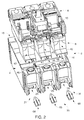
FIG. 2 depicts a partially exploded view of the multi-phase circuit breaker assembly ofFIG. 1 ; -
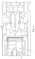
FIG. 3 depicts a non-conductive circuit breaker connector joining a circuit breaker cassette to the circuit breaker housing, in accordance with an exemplary embodiment; -
FIG. 4 depicts another view of the non-conductive circuit breaker connector ofFIG. 3 ; -
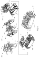
FIG. 5 depicts steps for assembling the multi-phase circuit breaker assembly, in accordance with an exemplary embodiment; and -
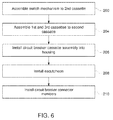
FIG. 6 depicts a flow chart illustrating a method of assembling the multi-phase circuit breaker assembly, in accordance with an exemplary embodiment. - The detailed description explains embodiments of the invention, together with advantages and features, by way of example with reference to the drawings.
- A circuit breaker assembly, in accordance with an exemplary embodiment, is indicated generally at 2, in
FIGs. 1 and2 .Circuit breaker assembly 2 includes ahousing 4 and a circuit breaker brick orcassette assembly 6. A cover orescutcheon 8 is arranged in circuitbreaker cassette assembly 6. Escutcheon 8 includes aswitch mechanism 10 that is selectively shiftable to open and close an electrical circuit. Theswitch mechanism 10 may be operated manually or in response to an undesirable circuit condition. -
Housing 4 includes a circuit breakercassette receiving portion 14 that houses circuit breaker pole cover, brick orcassette assembly 6, afirst connector portion 16, and an opposing,second connector portion 18.First connector portion 16 houses a first plurality of connector lugs (not shown) andsecond connector portion 18 houses a second plurality of connector lugs (also not shown). The first and second pluralities of connector lugs provide an electrical interface to circuitbreaker cassette assembly 6 for a source of electricity and an electrical load.Housing 4 also includes a plurality ofconnector mounting members 21.Connector mounting members 21 include a firstconnector mounting member 24, a secondconnector mounting member 25, and a thirdconnector mounting member 26. - In the exemplary embodiment shown, circuit
breaker cassette assembly 6 includes a firstcircuit breaker cassette 40, a secondcircuit breaker cassette 41, and a thirdcircuit breaker cassette 42. Circuit breaker cassettes 40-42 may be operatively connected through inter-engaging linkages (not shown) and/or throughswitch member 10. Circuitbreaker cassette assembly 6 also includes a plurality ofconnector receiving zones 44. More specifically, firstcircuit breaker cassette 40 includes a firstconnector receiving zone 46, secondcircuit breaker cassette 41 includes a secondconnector receiving zone 47, and thirdcircuit breaker cassette 42 includes a thirdconnector receiving zone 48. - When circuit
breaker cassette assembly 6 is installed inhousing 4, first, second, and third circuit breaker connector receiving zones 46-48 register with corresponding ones of first, second, and third connector mounting members 24-26. At this point, a plurality of circuitbreaker connector members 60 are installed to join circuitbreaker cassette assembly 6 andhousing 4. In accordance with an aspect of an exemplary embodiment, circuitbreaker conductor members 60 are non-conductive to electricity and may include a first non-conductive circuitbreaker connector member 64 extends through firstconnector mounting member 24 into firstconnector receiving zone 46, a second non-conductive circuitbreaker connector member 65 extends through secondconnector mounting member 25 into secondconnector receiving zone 47, and a third non-conductive circuitbreaker connector member 66 extends through thirdconnector mounting member 26 into thirdconnector receiving zone 48. It should however be understood that circuitbreaker connector members 60 may also be conductive to electricity if so desired. - Reference will now follow to
FIGs. 3 and4 in describing firstconnector mounting member 24, firstconnector receiving zone 46, and first non-conductive circuitbreaker connector member 64 with an understanding that the remaining circuitbreaker mounting members breaker receiving zones breaker connector members - First
connector mounting member 24 includes afirst end 70, asecond end 71 and anintermediate portion 72 extending therebetween.Intermediate portion 72 defines aconnector passage 74 that substantially aligns with firstconnector receiving zone 46. In accordance with an aspect of an exemplary embodiment, firstconnector receiving zone 46 defines anexhaust duct 80 that provides a passage for gases to pass from firstcircuit breaker cassette 40. Gases may be generated during a fault condition.Exhaust duct 80 includes a firstangled surface 82 and a secondangled surface 83. - First non-conductive circuit
breaker connector member 64 includes abody 90 formed from an electrically non-conducting, or electrically insulative, plastic. Of course, other non-electrically conducting materials may also be employed. Further, it should be understood thatbody 90 could be formed from an electrically conductive material that is encased in a non-electrically conductive coating.Body 90 includes afirst portion 92 and asecond portion 93.First portion 92 is linked tosecond portion 93 through a connecting portion (not separately labeled) defining an elasticallydeformable hinge 95. Elasticallydeformable hinge 95 includes a firstangled surface portion 97 and a secondangled surface portion 98 that form a generally v-shaped end portion (not separately labeled) of first non-conductive circuitbreaker connector member 64. Elastically deformable hinge 95 also includes a chamferedsurface portion 100. When installed in firstconnector receiving zone 46, first and secondangled surface portions angled surfaces angled exhaust channels surface portion 100 establishes a preload on firstconnector receiving zone 46 to provide a biasing force which retains firstcircuit breaker cassette 40 tohousing 4. - First non-conductive circuit
breaker connector member 64 also includes a first elastically deformable lockingarm member 110 extending from firstangled surface portion 97 and a second elastically deformable lockingarm member 111 extending from secondangled surface portion 98. First and second elastically deformablelocking arm members second portions breaker connector member 64 is passed throughconnector passage 74 and then extend outwardly upon passing into firstconnector receiving zone 46. In this manner, first non-conductive circuitbreaker connector member 64 snap-fittingly engages with firstconnector mounting member 24 to secure firstcircuit breaker cassette 40 inhousing 4. -
FIG. 5 and6 depict steps for assemblingcircuit breaker assembly 2 in accordance with an aspect of an exemplary embodiment. Initially,switch mechanism 10 is installed to secondcircuit breaker cassette 41 as shown at 200. At this point, firstcircuit breaker cassette 40 and thirdcircuit breaker cassette 42 may be assembled to secondcircuit breaker cassette 41 forming circuitbreaker cassette assembly 6 as shown at 204. Circuitbreaker cassette assembly 6 is installed into circuit breakercassette receiving portion 14 ofhousing 4, as shown at 206, andescutcheon 10 is installed as shown at 208. At this point, non-conductive circuitbreaker connector members 60 may be readily and easily installed into corresponding ones of connector receiving zones 46-48 through connector mounting members 24-26 to form multi-phasecircuit breaker assembly 2 as shown at 210. As can be seen inFIG. 5 , circuitbreaker connector members 60 may be installed without the need for complex manipulation or tooling thereby simplifying an overall assembly process forcircuit breaker assembly 2. - At this point it should be understood that the exemplary embodiments describe a non-conductive circuit breaker connector member that joins a circuit breaker cassette and a circuit breaker housing. By forming the connector from a material that does not conduct electricity, undesirable flow paths to ground may be eliminated. Further, in addition to eliminating undesirable flow paths to ground, the non-conductive circuit breaker connector member serves a dual purpose of guiding gases that may be generated during a fault condition from housing in a desired direction. It should also be understood that while shown as individual elements, the non-conductive circuit breaker connector members may be joined or ganged together as a single unit through, for example, one or more connecting webs. Further, it should be understood that, for example, a single non-electrically conductive circuit breaker connector member may be employed to join more than a single cassette to the housing.
- In addition, the non-conductive circuit breaker connector members reduce manufacturing complexity and improve automation by eliminating the need for installing other types of mechanical fasteners. The snap-fit provided by the non-conductive circuit breaker connector members simplifies manufacturing techniques necessary to form a circuit breaker. More specifically, the non-electrically conductive circuit breaker connector members eliminate complex or not readily accessible fastener locations and the need for screws, which increase manufacturing costs and complexity. Further, while shown as being installed from a bottom portion of the circuit breaker assembly, the non-conductive circuit breaker connector members may be installed in other locations.
- The terminology used herein is for the purpose of describing particular embodiments only and is not intended to be limiting of the invention. As used herein, the singular forms "a", "an" and "the" are intended to include the plural forms as well, unless the context clearly indicates otherwise. It will be further understood that the terms "comprises" and/or "comprising," when used in this specification, specify the presence of stated features, integers, steps, operations, elements, and/or components, but do not preclude the presence or addition of one more other features, integers, steps, operations, element components, and/or groups thereof.
- While the invention has been described in detail in connection with only a limited number of embodiments, it should be readily understood that the invention is not limited to such disclosed embodiments. Rather, the invention can be modified to incorporate any number of variations, alterations, substitutions or equivalent arrangements not heretofore described, but which are commensurate with the scope of the invention. Additionally, while various embodiments of the invention have been described, it is to be understood that aspects of the invention may include only some of the described embodiments. Accordingly, the invention is not to be seen as limited by the foregoing description, but is only limited by the scope of the appended claims.
- Various aspects and embodiments of the present invention are defined by the following numbered clauses:
- 1. A circuit breaker assembly comprising:
- a circuit breaker cassette including a connector receiving zone;
- a housing receptive of the circuit breaker cassette, the housing including a connector mounting member; and
- a circuit breaker connector member snap-fittingly extending into the connector receiving zone through the connector mounting member joining the circuit breaker cassette and the housing.
- 2. The circuit breaker assembly according to clause 1, wherein the connector mounting member includes a first end, a second end, and an intermediate portion extending therebetween, the second end being cantilevered from the housing.
- 3. The circuit breaker assembly according to any preceding clause, wherein the circuit breaker connector member includes at least one locking arm member engaging the second end of the connector mounting member.
- 4. The circuit breaker assembly according to any preceding clause, wherein the at least one locking arm member comprises an elastically deformable arm member.
- 5. The circuit breaker assembly according to any preceding clause, wherein the circuit breaker connector member is non-conductive to electricity.
- 6. The circuit breaker assembly according to any preceding clause, wherein the circuit breaker connector member includes a first portion, a second portion, and a connecting portion, the connecting portion defining an elastically deformable hinge.
- 7. The circuit breaker assembly according to any preceding clause, wherein the connector receiving zone defines an exhaust duct configured to direct gases from the circuit breaker cassette.
- 8. The circuit breaker assembly according to any preceding clause, wherein the circuit breaker connector member includes an angled surface portion extending into the exhaust duct, the angled surface portion being configured and disposed to channel exhaust gases passing from the exhaust duct in a desired direction.
- 9. The circuit breaker assembly according to any preceding clause, wherein the circuit breaker connector member is formed from plastic.
- 10. A circuit breaker assembly comprising:
- a plurality of circuit breaker cassettes, each of the plurality of circuit breaker cassettes including a connector receiving zone;
- a housing receptive of the plurality of circuit breaker cassettes, the housing including a plurality of connector mounting members corresponding to each of the plurality of circuit breaker cassettes; and
- one or more circuit breaker connector members snap-fittingly extending into one or more of the connector receiving zones through one or more connector mounting members joining the plurality of circuit breaker cassettes and the housing.
- 11. The circuit breaker assembly according to any preceding clause, wherein each connector mounting member includes a first end, a second end, and an intermediate portion extending therebetween, the second end being cantilevered from the housing.
- 12. The circuit breaker assembly according to any preceding clause, wherein each of the one or more circuit breaker connector members includes at least one locking arm member engaging the second end of the corresponding connector mounting member.
- 13. The circuit breaker assembly according to any preceding clause, wherein the at least one locking arm member comprises an elastically deformable arm member.
- 14. The circuit breaker assembly according to any preceding clause, wherein each of the one or more circuit breaker connector members is non-conductive to electricity.
- 15. The circuit breaker assembly according to any preceding clause, wherein each of the one or more circuit breaker connector members includes a first portion, a second portion, and a connecting portion, the connecting portion defining an elastically deformable hinge.
- 16. The circuit breaker assembly according to any preceding clause, wherein each connector receiving zone defines an exhaust duct configured to direct gases from the corresponding circuit breaker cassette.
- 17. The circuit breaker assembly according to any preceding clause, wherein each of the one or more circuit breaker connector members includes an angled surface portion extending into the exhaust duct, the angled surface portion being configured and disposed to channel exhaust gases passing from the exhaust duct in a desired direction.
- 18. The circuit breaker assembly according to any preceding clause, wherein each of the one or more circuit breaker connector members is formed from plastic.
- 19. The circuit breaker assembly according to any preceding clause, wherein the plurality of circuit breaker cassettes including at least three circuit breaker cassettes mounted in the housing.
- 20. The circuit breaker assembly according to any preceding clause, wherein the plurality of circuit breaker cassettes are operatively connected.
- 21. A method of assembling a circuit breaker assembly comprising:
- installing at least one circuit breaker cassette into a cassette receiving portion of a housing; and
- snap-fittingly installing at least one circuit breaker connector member between the housing and the at least one circuit breaker cassette.
- 22. The method of any preceding clause, wherein installing the at least one circuit breaker cassette into the cassette receiving zone includes installing a circuit breaker cassette assembly comprising a plurality of circuit breaker cassettes.
- 23. The method of any preceding clause, wherein snap-fittingly installing the at least one circuit breaker connector member includes snap-fittingly installing a circuit breaker connector member between the housing and one or more of the plurality of circuit breaker cassettes.
Claims (15)
- A circuit breaker assembly comprising:a circuit breaker cassette including a connector receiving zone;a housing receptive of the circuit breaker cassette, the housing including a connector mounting member; anda circuit breaker connector member snap-fittingly extending into the connector receiving zone through the connector mounting member joining the circuit breaker cassette and the housing.
- The circuit breaker assembly according to claim 1, wherein the connector mounting member includes a first end, a second end, and an intermediate portion extending therebetween, the second end being cantilevered from the housing.
- The circuit breaker assembly according to claim 2, wherein the circuit breaker connector member includes at least one locking arm member engaging the second end of the connector mounting member.
- The circuit breaker assembly according to claim 3, wherein the at least one locking arm member comprises an elastically deformable arm member.
- The circuit breaker assembly according to any preceding claim, wherein the circuit breaker connector member is non-conductive to electricity.
- The circuit breaker assembly according to any preceding claim, wherein the circuit breaker connector member includes a first portion, a second portion, and a connecting portion, the connecting portion defining an elastically deformable hinge.
- The circuit breaker assembly according to any preceding claim, wherein the connector receiving zone defines an exhaust duct configured to direct gases from the circuit breaker cassette.
- The circuit breaker assembly according to claim 7, wherein the circuit breaker connector member includes an angled surface portion extending into the exhaust duct, the angled surface portion being configured and disposed to channel exhaust gases passing from the exhaust duct in a desired direction.
- The circuit breaker assembly according to any preceding claim, wherein the circuit breaker connector member is formed from plastic.
- A circuit breaker assembly comprising:a plurality of circuit breaker cassettes, each of the plurality of circuit breaker cassettes including a connector receiving zone;a housing receptive of the plurality of circuit breaker cassettes, the housing including a plurality of connector mounting members corresponding to each of the plurality of circuit breaker cassettes; andone or more circuit breaker connector members snap-fittingly extending into one or more of the connector receiving zones through one or more connector mounting members joining the plurality of circuit breaker cassettes and the housing.
- The circuit breaker assembly according to claim 10, wherein the plurality of circuit breaker cassettes including at least three circuit breaker cassettes mounted in the housing.
- The circuit breaker assembly according to claim 10 or 11, wherein the plurality of circuit breaker cassettes are operatively connected.
- A method of assembling a circuit breaker assembly comprising:installing at least one circuit breaker cassette into a cassette receiving portion of a housing; andsnap-fittingly installing at least one circuit breaker connector member between the housing and the at least one circuit breaker cassette.
- The method of claim 13, wherein installing the at least one circuit breaker cassette into the cassette receiving zone includes installing a circuit breaker cassette assembly comprising a plurality of circuit breaker cassettes.
- The method of claim 14, wherein snap-fittingly installing the at least one circuit breaker connector member includes snap-fittingly installing a circuit breaker connector member between the housing and one or more of the plurality of circuit breaker cassettes.
Applications Claiming Priority (1)
| Application Number | Priority Date | Filing Date | Title |
|---|---|---|---|
| IN1119CH2015 | 2015-03-06 |
Publications (2)
| Publication Number | Publication Date |
|---|---|
| EP3065157A1 true EP3065157A1 (en) | 2016-09-07 |
| EP3065157B1 EP3065157B1 (en) | 2019-07-31 |
Family
ID=55451135
Family Applications (1)
| Application Number | Title | Priority Date | Filing Date |
|---|---|---|---|
| EP16158521.1A Active EP3065157B1 (en) | 2015-03-06 | 2016-03-03 | Circuit breaker assembly including a circuit breaker connector member |
Country Status (3)
| Country | Link |
|---|---|
| US (1) | US10276336B2 (en) |
| EP (1) | EP3065157B1 (en) |
| CN (1) | CN106409618B (en) |
Cited By (1)
| Publication number | Priority date | Publication date | Assignee | Title |
|---|---|---|---|---|
| EP4465335A4 (en) * | 2022-01-13 | 2025-10-22 | Ls Electric Co Ltd | Circuit breaker |
Citations (3)
| Publication number | Priority date | Publication date | Assignee | Title |
|---|---|---|---|---|
| DE69504258T2 (en) * | 1994-07-29 | 1999-02-18 | Schneider Electric S.A., Boulogne-Billancourt | Multipolar differential switch |
| EP2009666A2 (en) * | 2007-06-28 | 2008-12-31 | General Electric Company | Circuit breaker |
| DE102011087582A1 (en) * | 2011-12-01 | 2013-06-06 | Siemens Aktiengesellschaft | Multi-pole electrical switch e.g. three-pole electrical switch has connector that is pushed into channel extending in parallel to side walls, by positive connection between side walls and connector respectively |
Family Cites Families (12)
| Publication number | Priority date | Publication date | Assignee | Title |
|---|---|---|---|---|
| US6064018A (en) * | 1998-10-23 | 2000-05-16 | General Electric Company | Molded case circuit breaker molded pole assembly |
| US6377144B1 (en) | 1999-11-03 | 2002-04-23 | General Electric Company | Molded case circuit breaker base and mid-cover assembly |
| US6204743B1 (en) * | 2000-02-29 | 2001-03-20 | General Electric Company | Dual connector strap for a rotary contact circuit breaker |
| EP1206783A2 (en) | 2000-03-03 | 2002-05-22 | General Electric Company | Contact depression stabilizer for 4 pole molded case circuit breaker |
| US20020122279A1 (en) | 2000-12-29 | 2002-09-05 | Greenberg Randall Lee | Circuit breaker operating handle |
| US20020153978A1 (en) | 2001-04-19 | 2002-10-24 | Greenberg Randall Lee | Four-pole molded case circuit breaker having staggered contact depression |
| US6750743B1 (en) * | 2003-05-13 | 2004-06-15 | General Electric Company | Integrated thermal and magnetic trip unit |
| US6933814B2 (en) | 2003-05-13 | 2005-08-23 | General Electric Company | Phase-to-phase isolation of cassette type circuit breakers |
| US6930573B2 (en) | 2003-08-29 | 2005-08-16 | General Electric Company | Interlocking cassettes for dimensional stability |
| US6930577B2 (en) * | 2003-09-15 | 2005-08-16 | General Electric Company | Circuit breaker lug cover and gasket |
| CN201708101U (en) | 2010-05-21 | 2011-01-12 | 薛文锋 | Fastener for connecting guide rail with circuit breaker |
| TWM466909U (en) * | 2013-06-19 | 2013-12-01 | Yi-De Pan | Improved structure of planetary limit switch |
-
2016
- 2016-02-11 US US15/041,971 patent/US10276336B2/en active Active
- 2016-03-03 EP EP16158521.1A patent/EP3065157B1/en active Active
- 2016-03-04 CN CN201610122797.1A patent/CN106409618B/en not_active Expired - Fee Related
Patent Citations (3)
| Publication number | Priority date | Publication date | Assignee | Title |
|---|---|---|---|---|
| DE69504258T2 (en) * | 1994-07-29 | 1999-02-18 | Schneider Electric S.A., Boulogne-Billancourt | Multipolar differential switch |
| EP2009666A2 (en) * | 2007-06-28 | 2008-12-31 | General Electric Company | Circuit breaker |
| DE102011087582A1 (en) * | 2011-12-01 | 2013-06-06 | Siemens Aktiengesellschaft | Multi-pole electrical switch e.g. three-pole electrical switch has connector that is pushed into channel extending in parallel to side walls, by positive connection between side walls and connector respectively |
Cited By (1)
| Publication number | Priority date | Publication date | Assignee | Title |
|---|---|---|---|---|
| EP4465335A4 (en) * | 2022-01-13 | 2025-10-22 | Ls Electric Co Ltd | Circuit breaker |
Also Published As
| Publication number | Publication date |
|---|---|
| US10276336B2 (en) | 2019-04-30 |
| CN106409618B (en) | 2019-09-03 |
| US20160260568A1 (en) | 2016-09-08 |
| EP3065157B1 (en) | 2019-07-31 |
| CN106409618A (en) | 2017-02-15 |
Similar Documents
| Publication | Publication Date | Title |
|---|---|---|
| US7834282B2 (en) | Method of sequentially actuating power supply switches including a neutrally connected switch | |
| JP6147768B2 (en) | Plug-in circuit breaker assembly including insulation retainer | |
| US9325158B2 (en) | Electrical enclosure including an integrated dead front and door | |
| US20090088029A1 (en) | Devices, Systems, and Methods for Coupling Electrical Conductors | |
| CA2849012A1 (en) | Modular solid dielectric switchgear | |
| CN104637741A (en) | Molded case circuit breaker | |
| JP2020536369A5 (en) | ||
| CN111326872A (en) | Conductors for power distribution systems | |
| WO2018236266A1 (en) | Electrical connector for fuel cell stack voltage monitoring | |
| WO2014143494A1 (en) | Heat reducing terminals including a surface having protrusions and electrical switching apparatus including the same | |
| CN102714110A (en) | Medium voltage circuit breaker | |
| EP3065157B1 (en) | Circuit breaker assembly including a circuit breaker connector member | |
| JP5116582B2 (en) | Earth leakage breaker | |
| EP3483912A1 (en) | Electrically conductive loop of circuit breaker | |
| CA2911355C (en) | Switching device assembly and adapter assembly therefor | |
| US20240356312A1 (en) | Electrical panelboard with arc fault protection and user interface | |
| US20240097384A1 (en) | Conductor assembly for a power distribution system | |
| EP2667394B1 (en) | Multiple-pole switch and/or circuit breaker for low voltage | |
| CN220651909U (en) | Contactor | |
| US20260005454A1 (en) | Multi-directional terminal block and method of making | |
| CN111755290A (en) | Connect conversion adapters and electrical equipment | |
| US9218928B2 (en) | Circuit breaker bail mechanism | |
| CN121359332A (en) | Distribution board with arc fault protection and user interface | |
| JP7386528B2 (en) | Quick connection terminal unit and switchboard | |
| CN211507409U (en) | Do benefit to contact piece limit structure who improves reliability |
Legal Events
| Date | Code | Title | Description |
|---|---|---|---|
| PUAI | Public reference made under article 153(3) epc to a published international application that has entered the european phase |
Free format text: ORIGINAL CODE: 0009012 |
|
| AK | Designated contracting states |
Kind code of ref document: A1 Designated state(s): AL AT BE BG CH CY CZ DE DK EE ES FI FR GB GR HR HU IE IS IT LI LT LU LV MC MK MT NL NO PL PT RO RS SE SI SK SM TR |
|
| AX | Request for extension of the european patent |
Extension state: BA ME |
|
| STAA | Information on the status of an ep patent application or granted ep patent |
Free format text: STATUS: REQUEST FOR EXAMINATION WAS MADE |
|
| 17P | Request for examination filed |
Effective date: 20170307 |
|
| RBV | Designated contracting states (corrected) |
Designated state(s): AL AT BE BG CH CY CZ DE DK EE ES FI FR GB GR HR HU IE IS IT LI LT LU LV MC MK MT NL NO PL PT RO RS SE SI SK SM TR |
|
| GRAP | Despatch of communication of intention to grant a patent |
Free format text: ORIGINAL CODE: EPIDOSNIGR1 |
|
| STAA | Information on the status of an ep patent application or granted ep patent |
Free format text: STATUS: GRANT OF PATENT IS INTENDED |
|
| RIC1 | Information provided on ipc code assigned before grant |
Ipc: H01H 9/34 20060101ALN20181207BHEP Ipc: H01H 71/02 20060101AFI20181207BHEP |
|
| INTG | Intention to grant announced |
Effective date: 20190107 |
|
| RIN1 | Information on inventor provided before grant (corrected) |
Inventor name: ABBASI, MUNEEB AHMED Inventor name: NEWASE, YATIN VILAS Inventor name: GUPTA, SIMHADRI RAMALINGESWARA RAO Inventor name: JIVANANI, ANURAG ARJUNDAS Inventor name: KADAM, GAJENDRA VIJAYKUMAR |
|
| GRAS | Grant fee paid |
Free format text: ORIGINAL CODE: EPIDOSNIGR3 |
|
| RAP1 | Party data changed (applicant data changed or rights of an application transferred) |
Owner name: ABB SCHWEIZ AG |
|
| GRAA | (expected) grant |
Free format text: ORIGINAL CODE: 0009210 |
|
| STAA | Information on the status of an ep patent application or granted ep patent |
Free format text: STATUS: THE PATENT HAS BEEN GRANTED |
|
| AK | Designated contracting states |
Kind code of ref document: B1 Designated state(s): AL AT BE BG CH CY CZ DE DK EE ES FI FR GB GR HR HU IE IS IT LI LT LU LV MC MK MT NL NO PL PT RO RS SE SI SK SM TR |
|
| REG | Reference to a national code |
Ref country code: CH Ref legal event code: EP Ref country code: GB Ref legal event code: FG4D |
|
| REG | Reference to a national code |
Ref country code: AT Ref legal event code: REF Ref document number: 1161810 Country of ref document: AT Kind code of ref document: T Effective date: 20190815 |
|
| REG | Reference to a national code |
Ref country code: IE Ref legal event code: FG4D |
|
| REG | Reference to a national code |
Ref country code: DE Ref legal event code: R096 Ref document number: 602016017571 Country of ref document: DE |
|
| REG | Reference to a national code |
Ref country code: NL Ref legal event code: MP Effective date: 20190731 |
|
| REG | Reference to a national code |
Ref country code: LT Ref legal event code: MG4D |
|
| REG | Reference to a national code |
Ref country code: AT Ref legal event code: MK05 Ref document number: 1161810 Country of ref document: AT Kind code of ref document: T Effective date: 20190731 |
|
| PG25 | Lapsed in a contracting state [announced via postgrant information from national office to epo] |
Ref country code: PT Free format text: LAPSE BECAUSE OF FAILURE TO SUBMIT A TRANSLATION OF THE DESCRIPTION OR TO PAY THE FEE WITHIN THE PRESCRIBED TIME-LIMIT Effective date: 20191202 Ref country code: NO Free format text: LAPSE BECAUSE OF FAILURE TO SUBMIT A TRANSLATION OF THE DESCRIPTION OR TO PAY THE FEE WITHIN THE PRESCRIBED TIME-LIMIT Effective date: 20191031 Ref country code: FI Free format text: LAPSE BECAUSE OF FAILURE TO SUBMIT A TRANSLATION OF THE DESCRIPTION OR TO PAY THE FEE WITHIN THE PRESCRIBED TIME-LIMIT Effective date: 20190731 Ref country code: SE Free format text: LAPSE BECAUSE OF FAILURE TO SUBMIT A TRANSLATION OF THE DESCRIPTION OR TO PAY THE FEE WITHIN THE PRESCRIBED TIME-LIMIT Effective date: 20190731 Ref country code: HR Free format text: LAPSE BECAUSE OF FAILURE TO SUBMIT A TRANSLATION OF THE DESCRIPTION OR TO PAY THE FEE WITHIN THE PRESCRIBED TIME-LIMIT Effective date: 20190731 Ref country code: LT Free format text: LAPSE BECAUSE OF FAILURE TO SUBMIT A TRANSLATION OF THE DESCRIPTION OR TO PAY THE FEE WITHIN THE PRESCRIBED TIME-LIMIT Effective date: 20190731 Ref country code: AT Free format text: LAPSE BECAUSE OF FAILURE TO SUBMIT A TRANSLATION OF THE DESCRIPTION OR TO PAY THE FEE WITHIN THE PRESCRIBED TIME-LIMIT Effective date: 20190731 Ref country code: BG Free format text: LAPSE BECAUSE OF FAILURE TO SUBMIT A TRANSLATION OF THE DESCRIPTION OR TO PAY THE FEE WITHIN THE PRESCRIBED TIME-LIMIT Effective date: 20191031 Ref country code: NL Free format text: LAPSE BECAUSE OF FAILURE TO SUBMIT A TRANSLATION OF THE DESCRIPTION OR TO PAY THE FEE WITHIN THE PRESCRIBED TIME-LIMIT Effective date: 20190731 |
|
| PG25 | Lapsed in a contracting state [announced via postgrant information from national office to epo] |
Ref country code: ES Free format text: LAPSE BECAUSE OF FAILURE TO SUBMIT A TRANSLATION OF THE DESCRIPTION OR TO PAY THE FEE WITHIN THE PRESCRIBED TIME-LIMIT Effective date: 20190731 Ref country code: GR Free format text: LAPSE BECAUSE OF FAILURE TO SUBMIT A TRANSLATION OF THE DESCRIPTION OR TO PAY THE FEE WITHIN THE PRESCRIBED TIME-LIMIT Effective date: 20191101 Ref country code: AL Free format text: LAPSE BECAUSE OF FAILURE TO SUBMIT A TRANSLATION OF THE DESCRIPTION OR TO PAY THE FEE WITHIN THE PRESCRIBED TIME-LIMIT Effective date: 20190731 Ref country code: IS Free format text: LAPSE BECAUSE OF FAILURE TO SUBMIT A TRANSLATION OF THE DESCRIPTION OR TO PAY THE FEE WITHIN THE PRESCRIBED TIME-LIMIT Effective date: 20191130 Ref country code: LV Free format text: LAPSE BECAUSE OF FAILURE TO SUBMIT A TRANSLATION OF THE DESCRIPTION OR TO PAY THE FEE WITHIN THE PRESCRIBED TIME-LIMIT Effective date: 20190731 Ref country code: RS Free format text: LAPSE BECAUSE OF FAILURE TO SUBMIT A TRANSLATION OF THE DESCRIPTION OR TO PAY THE FEE WITHIN THE PRESCRIBED TIME-LIMIT Effective date: 20190731 |
|
| PG25 | Lapsed in a contracting state [announced via postgrant information from national office to epo] |
Ref country code: TR Free format text: LAPSE BECAUSE OF FAILURE TO SUBMIT A TRANSLATION OF THE DESCRIPTION OR TO PAY THE FEE WITHIN THE PRESCRIBED TIME-LIMIT Effective date: 20190731 |
|
| PG25 | Lapsed in a contracting state [announced via postgrant information from national office to epo] |
Ref country code: RO Free format text: LAPSE BECAUSE OF FAILURE TO SUBMIT A TRANSLATION OF THE DESCRIPTION OR TO PAY THE FEE WITHIN THE PRESCRIBED TIME-LIMIT Effective date: 20190731 Ref country code: PL Free format text: LAPSE BECAUSE OF FAILURE TO SUBMIT A TRANSLATION OF THE DESCRIPTION OR TO PAY THE FEE WITHIN THE PRESCRIBED TIME-LIMIT Effective date: 20190731 Ref country code: EE Free format text: LAPSE BECAUSE OF FAILURE TO SUBMIT A TRANSLATION OF THE DESCRIPTION OR TO PAY THE FEE WITHIN THE PRESCRIBED TIME-LIMIT Effective date: 20190731 Ref country code: DK Free format text: LAPSE BECAUSE OF FAILURE TO SUBMIT A TRANSLATION OF THE DESCRIPTION OR TO PAY THE FEE WITHIN THE PRESCRIBED TIME-LIMIT Effective date: 20190731 |
|
| PG25 | Lapsed in a contracting state [announced via postgrant information from national office to epo] |
Ref country code: CZ Free format text: LAPSE BECAUSE OF FAILURE TO SUBMIT A TRANSLATION OF THE DESCRIPTION OR TO PAY THE FEE WITHIN THE PRESCRIBED TIME-LIMIT Effective date: 20190731 Ref country code: SM Free format text: LAPSE BECAUSE OF FAILURE TO SUBMIT A TRANSLATION OF THE DESCRIPTION OR TO PAY THE FEE WITHIN THE PRESCRIBED TIME-LIMIT Effective date: 20190731 Ref country code: IS Free format text: LAPSE BECAUSE OF FAILURE TO SUBMIT A TRANSLATION OF THE DESCRIPTION OR TO PAY THE FEE WITHIN THE PRESCRIBED TIME-LIMIT Effective date: 20200224 Ref country code: SK Free format text: LAPSE BECAUSE OF FAILURE TO SUBMIT A TRANSLATION OF THE DESCRIPTION OR TO PAY THE FEE WITHIN THE PRESCRIBED TIME-LIMIT Effective date: 20190731 |
|
| REG | Reference to a national code |
Ref country code: DE Ref legal event code: R097 Ref document number: 602016017571 Country of ref document: DE |
|
| PLBE | No opposition filed within time limit |
Free format text: ORIGINAL CODE: 0009261 |
|
| STAA | Information on the status of an ep patent application or granted ep patent |
Free format text: STATUS: NO OPPOSITION FILED WITHIN TIME LIMIT |
|
| PG2D | Information on lapse in contracting state deleted |
Ref country code: IS |
|
| PG25 | Lapsed in a contracting state [announced via postgrant information from national office to epo] |
Ref country code: IS Free format text: LAPSE BECAUSE OF FAILURE TO SUBMIT A TRANSLATION OF THE DESCRIPTION OR TO PAY THE FEE WITHIN THE PRESCRIBED TIME-LIMIT Effective date: 20191030 |
|
| 26N | No opposition filed |
Effective date: 20200603 |
|
| PG25 | Lapsed in a contracting state [announced via postgrant information from national office to epo] |
Ref country code: SI Free format text: LAPSE BECAUSE OF FAILURE TO SUBMIT A TRANSLATION OF THE DESCRIPTION OR TO PAY THE FEE WITHIN THE PRESCRIBED TIME-LIMIT Effective date: 20190731 |
|
| REG | Reference to a national code |
Ref country code: DE Ref legal event code: R119 Ref document number: 602016017571 Country of ref document: DE |
|
| PG25 | Lapsed in a contracting state [announced via postgrant information from national office to epo] |
Ref country code: MC Free format text: LAPSE BECAUSE OF FAILURE TO SUBMIT A TRANSLATION OF THE DESCRIPTION OR TO PAY THE FEE WITHIN THE PRESCRIBED TIME-LIMIT Effective date: 20190731 |
|
| REG | Reference to a national code |
Ref country code: CH Ref legal event code: PL |
|
| REG | Reference to a national code |
Ref country code: BE Ref legal event code: MM Effective date: 20200331 |
|
| PG25 | Lapsed in a contracting state [announced via postgrant information from national office to epo] |
Ref country code: LU Free format text: LAPSE BECAUSE OF NON-PAYMENT OF DUE FEES Effective date: 20200303 |
|
| PG25 | Lapsed in a contracting state [announced via postgrant information from national office to epo] |
Ref country code: IE Free format text: LAPSE BECAUSE OF NON-PAYMENT OF DUE FEES Effective date: 20200303 Ref country code: LI Free format text: LAPSE BECAUSE OF NON-PAYMENT OF DUE FEES Effective date: 20200331 Ref country code: DE Free format text: LAPSE BECAUSE OF NON-PAYMENT OF DUE FEES Effective date: 20201001 Ref country code: CH Free format text: LAPSE BECAUSE OF NON-PAYMENT OF DUE FEES Effective date: 20200331 Ref country code: FR Free format text: LAPSE BECAUSE OF NON-PAYMENT OF DUE FEES Effective date: 20200331 |
|
| PG25 | Lapsed in a contracting state [announced via postgrant information from national office to epo] |
Ref country code: BE Free format text: LAPSE BECAUSE OF NON-PAYMENT OF DUE FEES Effective date: 20200331 |
|
| GBPC | Gb: european patent ceased through non-payment of renewal fee |
Effective date: 20200303 |
|
| PG25 | Lapsed in a contracting state [announced via postgrant information from national office to epo] |
Ref country code: GB Free format text: LAPSE BECAUSE OF NON-PAYMENT OF DUE FEES Effective date: 20200303 |
|
| PG25 | Lapsed in a contracting state [announced via postgrant information from national office to epo] |
Ref country code: IT Free format text: LAPSE BECAUSE OF NON-PAYMENT OF DUE FEES Effective date: 20200303 |
|
| PG25 | Lapsed in a contracting state [announced via postgrant information from national office to epo] |
Ref country code: MT Free format text: LAPSE BECAUSE OF FAILURE TO SUBMIT A TRANSLATION OF THE DESCRIPTION OR TO PAY THE FEE WITHIN THE PRESCRIBED TIME-LIMIT Effective date: 20190731 Ref country code: CY Free format text: LAPSE BECAUSE OF FAILURE TO SUBMIT A TRANSLATION OF THE DESCRIPTION OR TO PAY THE FEE WITHIN THE PRESCRIBED TIME-LIMIT Effective date: 20190731 |
|
| PG25 | Lapsed in a contracting state [announced via postgrant information from national office to epo] |
Ref country code: MK Free format text: LAPSE BECAUSE OF FAILURE TO SUBMIT A TRANSLATION OF THE DESCRIPTION OR TO PAY THE FEE WITHIN THE PRESCRIBED TIME-LIMIT Effective date: 20190731 |