EP3065037A1 - Touch device and driving method - Google Patents
Touch device and driving method Download PDFInfo
- Publication number
- EP3065037A1 EP3065037A1 EP14882147.3A EP14882147A EP3065037A1 EP 3065037 A1 EP3065037 A1 EP 3065037A1 EP 14882147 A EP14882147 A EP 14882147A EP 3065037 A1 EP3065037 A1 EP 3065037A1
- Authority
- EP
- European Patent Office
- Prior art keywords
- touch
- touch panel
- controller
- approaching
- transmitters
- Prior art date
- Legal status (The legal status is an assumption and is not a legal conclusion. Google has not performed a legal analysis and makes no representation as to the accuracy of the status listed.)
- Granted
Links
Images


Classifications
-
- G—PHYSICS
- G06—COMPUTING OR CALCULATING; COUNTING
- G06F—ELECTRIC DIGITAL DATA PROCESSING
- G06F3/00—Input arrangements for transferring data to be processed into a form capable of being handled by the computer; Output arrangements for transferring data from processing unit to output unit, e.g. interface arrangements
- G06F3/01—Input arrangements or combined input and output arrangements for interaction between user and computer
- G06F3/03—Arrangements for converting the position or the displacement of a member into a coded form
- G06F3/041—Digitisers, e.g. for touch screens or touch pads, characterised by the transducing means
- G06F3/042—Digitisers, e.g. for touch screens or touch pads, characterised by the transducing means by opto-electronic means
- G06F3/0421—Digitisers, e.g. for touch screens or touch pads, characterised by the transducing means by opto-electronic means by interrupting or reflecting a light beam, e.g. optical touch-screen
-
- G—PHYSICS
- G06—COMPUTING OR CALCULATING; COUNTING
- G06F—ELECTRIC DIGITAL DATA PROCESSING
- G06F3/00—Input arrangements for transferring data to be processed into a form capable of being handled by the computer; Output arrangements for transferring data from processing unit to output unit, e.g. interface arrangements
- G06F3/01—Input arrangements or combined input and output arrangements for interaction between user and computer
- G06F3/03—Arrangements for converting the position or the displacement of a member into a coded form
- G06F3/041—Digitisers, e.g. for touch screens or touch pads, characterised by the transducing means
- G06F3/0412—Digitisers structurally integrated in a display
-
- G—PHYSICS
- G06—COMPUTING OR CALCULATING; COUNTING
- G06F—ELECTRIC DIGITAL DATA PROCESSING
- G06F3/00—Input arrangements for transferring data to be processed into a form capable of being handled by the computer; Output arrangements for transferring data from processing unit to output unit, e.g. interface arrangements
- G06F3/01—Input arrangements or combined input and output arrangements for interaction between user and computer
- G06F3/03—Arrangements for converting the position or the displacement of a member into a coded form
- G06F3/041—Digitisers, e.g. for touch screens or touch pads, characterised by the transducing means
- G06F3/0416—Control or interface arrangements specially adapted for digitisers
- G06F3/04166—Details of scanning methods, e.g. sampling time, grouping of sub areas or time sharing with display driving
-
- G—PHYSICS
- G06—COMPUTING OR CALCULATING; COUNTING
- G06F—ELECTRIC DIGITAL DATA PROCESSING
- G06F3/00—Input arrangements for transferring data to be processed into a form capable of being handled by the computer; Output arrangements for transferring data from processing unit to output unit, e.g. interface arrangements
- G06F3/01—Input arrangements or combined input and output arrangements for interaction between user and computer
- G06F3/03—Arrangements for converting the position or the displacement of a member into a coded form
- G06F3/041—Digitisers, e.g. for touch screens or touch pads, characterised by the transducing means
- G06F3/043—Digitisers, e.g. for touch screens or touch pads, characterised by the transducing means using propagating acoustic waves
- G06F3/0436—Digitisers, e.g. for touch screens or touch pads, characterised by the transducing means using propagating acoustic waves in which generating transducers and detecting transducers are attached to a single acoustic waves transmission substrate
-
- G—PHYSICS
- G06—COMPUTING OR CALCULATING; COUNTING
- G06F—ELECTRIC DIGITAL DATA PROCESSING
- G06F2203/00—Indexing scheme relating to G06F3/00 - G06F3/048
- G06F2203/041—Indexing scheme relating to G06F3/041 - G06F3/045
- G06F2203/04101—2.5D-digitiser, i.e. digitiser detecting the X/Y position of the input means, finger or stylus, also when it does not touch, but is proximate to the digitiser's interaction surface and also measures the distance of the input means within a short range in the Z direction, possibly with a separate measurement setup
-
- G—PHYSICS
- G06—COMPUTING OR CALCULATING; COUNTING
- G06F—ELECTRIC DIGITAL DATA PROCESSING
- G06F2203/00—Indexing scheme relating to G06F3/00 - G06F3/048
- G06F2203/041—Indexing scheme relating to G06F3/041 - G06F3/045
- G06F2203/04106—Multi-sensing digitiser, i.e. digitiser using at least two different sensing technologies simultaneously or alternatively, e.g. for detecting pen and finger, for saving power or for improving position detection
Definitions
- the present disclosure relates to the field of display technology, and in particular, to a touch device and a method for driving the same.
- a touch substrate may be omitted from a capacitive touch screen by using the In-Cell touch technology, such that the whole display module may be manufactured in a thinner way.
- a structural diagram of a liquid crystal display screen using the In-Cell touch technology is shown as Fig. 1 in which touch driving electrodes (Tx) and touch sensing electrodes (Rx) are manufactured on a glass substrate on an array substrate side of the liquid crystal display panel.
- the Tx lines share same lines with common electrodes (Vcom) lines.
- Vcom common electrodes
- Various parasitic capacitances and coupling capacitances may occur in the liquid crystal display screen (i.e.
- each of Gate1, Gate2, ..., Gate n denotes a gate scan line for each line of pixels, respectively; each of Data1, Data2, ..., Data n denotes a data scan line for each line of pixels, respectively; C LC denotes a capacitance between the liquid crystal display panels; and Cs denotes a storage capacitance.
- Fig. 2(a) shows an example of timings for display scanning and touch scanning of an Out-Cell capacitive touch screen, in which al - a60 denote periods for display scanning and t1-t60 denote periods for touch scanning.
- the touch scanning is performed in synchronization with the picture refresh since the Out-Cell capacitive touch screen is not affected by TFT driving signals.
- the display scanning and touch scanning for a capacitive touch screen are performed in synchronization and they are not affected by each other.
- the scanning frequency for the display scanning is 60 Hz
- the scanning frequency for the touch scanning is 100 Hz.
- FIG. 2(b) shows an example of timings for display scanning and touch scanning of a capacitive touch screen using the In-Cell touch technology, in which a1 - a60 denote periods for display scanning and t1-t60 denote periods for touch scanning.
- the In-Cell touch technology utilizes a scanning mode in which the scanning is performed in a blank interval between two frames of pictures.
- the display scanning and touch scanning for the liquid crystal display screen shall be performed in a time-sharing manner.
- the scanning frequency for the display scanning is 40 Hz
- the scanning frequency for the touch scanning is 40 Hz.
- FIG. 3 A system block diagram of a liquid crystal display screen using the In-Cell touch technology is shown as Fig. 3 .
- Touch scanning time, t, assigned to each frame is limited due to the limitation of data transmission rates of the timing controller and driver and charging time of sub-pixels.
- t is small, scannings of Tx and Rx cannot be finished, and therefore t is to be increased appropriately.
- the direct way to increase t is to increase the scanning time of a frame, and the assigned touch scanning time is increased accordingly. However, this will lead to a lower frame rate, and the quality of the picture will be deteriorated. Flickering, smearing, or the like will occur.
- liquid crystal display screen using the In-Cell touch technology utilizes a time-sharing driving method, the liquid crystal display screen cannot operate at a higher display refresh rate when there is no touch.
- Embodiments of the present disclosure provide a touch device and a method for driving the same which is capable of enabling the touch device to operate at a higher display refresh rate when there is no touch and improving the display effect.
- An embodiment of the present disclosure provides a touch device comprising: a touch panel configured to display content, to refresh the displayed content according to a display scanning signal, and capable of sensing a touch on the touch panel and cooperating with a touch controller to scan the touch; a timing controller configured to output the display scanning signal to the touch panel; the touch controller configured to scan and locate the touch on the touch panel; a sensor configured to detect whether there is an object contacting or approaching the touch panel and to output a first indication signal if there is no object contacting or approaching the touch panel and a second indication signal if there is an object contacting or approaching the touch panel; and a controller configured to control the timing controller to output a first display scanning signal when the first indication signal is received and to control the timing controller to output a second display scanning signal when the second indication signal is received, wherein the scanning frequency of the first display scanning signal is higher than that of the second display scanning signal.
- the controller is further configured to: control the touch controller to not operate when the first indication signal is received; and control the touch controller to begin operating when the second indication signal is received.
- the touch device has a timing controller that outputs different display scanning signals when there is a touch on the touch panel and when there is no touch on the touch panel. Further, when there is no touch, the touch controller does not operate. Therefore, the touch device provided by an embodiment of the present disclosure may operate at a higher display refresh rate when there is no touch, thereby improving display effect and reducing power consumption.
- the senor comprises transmitters and receivers, wherein the transmitters are configured to transmit light wave or sound wave towards proximity of the touch panel; and the receivers are configured to receive the light wave or the sound wave and determine whether there is an object contacting or approaching the touch panel based on the change in the light wave or sound wave.
- the sensor comprises the transmitters and the receivers, it is more convenient and simpler to detect whether there is an object contacting or approaching the touch panel in practice.
- the number of the transmitters is equal to that of the receivers.
- the transmitters are located in four corner areas of the touch panel.
- the number of the transmitters is two.
- the transmitters are ultrasonic transmitters or infrared transmitters.
- the transmitters are ultrasonic transmitters or infrared transmitters, the principles are simple and stable in practice.
- the receivers are located in four corner areas of the touch panel.
- the receivers are ultrasonic receivers or infrared receivers.
- the receivers are ultrasonic receivers or infrared receivers, the principles are simple and stable in practice.
- An embodiment of the present disclosure further provides a method for driving a touch device, comprising: detecting whether there is an object contacting or approaching a touch panel of the touch device, wherein the touch panel is configured to display content, to refresh the displayed content according to a display scanning signal, and is capable of sensing a touch on the touch panel and cooperating with a touch controller to scan the touch; outputting a second display scanning signal to the touch panel if there is an object contacting or approaching the touch panel; and outputting a first display scanning signal to the touch panel if there is no object contacting or approaching the touch panel, wherein the scanning frequency of the first display scanning signal is higher than that of the second display scanning signal.
- the method for driving further comprises: controlling the touch controller to not operate when the first indication signal is received; and controlling the touch controller to begin operating when the second indication signal is received.
- the method for driving a touch device outputs different display scanning signals to the touch panel when there is a touch on the touch panel and when there is no touch on the touch panel. Further, when there is no touch, the touch controller does not operate. Therefore, the method for driving provided by an embodiment of the present disclosure may enable the touch device to operate at a higher display refresh rate when there is no touch, thereby reducing power consumption of the touch device.
- the detecting of whether there is an object contacting or approaching a touch panel of the touch device further comprises: transmitting light wave or sound wave towards proximity of the touch panel; and receiving the light wave or the sound wave and determining whether there is an object contacting or approaching the touch panel based on the change in the light wave or sound wave.
- Embodiments of the present disclosure provide a touch device and a method for driving the same which enable the touch device to operate at a higher display refresh rate when there is no touch and improve the display effect.
- Fig. 4 is a diagram showing a touch device 400 according to an embodiment of the present disclosure.
- the touch device 400 according to the embodiment of the present disclosure comprises: a touch panel 40, a timing controller 41, a touch controller 42, a controller 43, and a sensor 44.
- the touch panel 40 displays content, refreshes the displayed content according to a display scanning signal, and is capable of sensing a touch on the touch panel 40 and cooperating with the touch controller 42 to scan the touch.
- the timing controller 41 is configured to output the display scanning signal to the touch panel 40.
- the touch controller 42 is configured to scan and locate the touch on the touch panel 40.
- the sensor 44 is configured to detect whether there is an object contacting or approaching the touch panel 40, and output a first indication signal to the controller 43 when there is no object contacting or approaching the touch panel 40 and a second indication signal to the controller 43 when there is an object contacting or approaching the touch panel 40.
- the controller 43 controls the timing controller 41 to output a first display scanning signal to the touch panel 40; and when the second indication signal is received from the sensor 44, the controller 43 controls the timing controller 41 to output a second display scanning signal to the touch panel 40.
- the scanning frequency of the first display scanning signal is higher than that of the second display scanning signal.
- the controller 43 When the first indication signal is received, the controller 43 further controls the touch controller 42 to not operate, and when the second indication signal is received, the controller 43 controls the touch controller 42 to begin operating.
- the first and second indication signals output by the sensor 44 may be a low level signal and a high level signal, and may also be digital signals.
- the first indication signal is a high level signal and the second indication signal is a low level signal is given.
- the sensor 44 When there is no object contacting or approaching the touch panel 40, the sensor 44 outputs a high level signal, and transmits the signal to the controller 43.
- the controller 43 controls the touch controller 42 to not operate, and controls the timing controller 41 to output the first display scanning signal.
- the sensor 44 When there is an object contacting or approaching the touch panel 40, the sensor 44 outputs a low level signal, and transmits the signal to the controller 43.
- the controller 43 in turn controls the timing controller 41 to output the second display scanning signal, and controls the touch controller 42 to begin operating. That is, the touch controller 42 begins to scan and locate the touch on the touch panel 40.
- the controller 43 may be an integrated circuit disposed directly in the touch panel or an integrated circuit disposed in a Flexible Printed Circuit (FPC). Further, it can also be disposed at other locations, and no limitation is imposed to its position in the embodiments of the present disclosure.
- FPC Flexible Printed Circuit
- the sensor 44 in the embodiment of the present disclosure comprises transmitters 51 and receivers 52.
- Fig. 5 is a diagram showing positions of transmitters 51 and receivers 52 in a touch device according to an embodiment of the present disclosure.
- the transmitters 51 are configured to transmit a light wave or a sound wave towards proximity of the touch panel 40.
- the receivers 52 are configured to receive the light wave or the sound wave, and determine whether there is an object contacting or approaching the touch panel based on the change in the light wave or the sound wave.
- the number of the transmitters 51 is equal to that of the receives 52.
- the number of transmitters 51 is two, and the transmitters 51 are located at the bottom left corner and bottom right corner of the touch panel 40, respectively.
- the transmitters may also be located at the top left corner and top right corner of the touch panel 40, respectively.
- the transmitters may be ultrasonic transmitters or infrared transmitters.
- the transmitters may be other types of sensors, such as, laser transmitters, or the like.
- the number of the receivers 52 is two, and the receivers 52 are located at the top left corner and top right corner of the touch panel 40, respectively.
- the receivers may also be located at the bottom left corner and bottom right corner of the touch panel 40, respectively.
- the receivers may be ultrasonic receivers or infrared receivers.
- the type of the receivers in the embodiments of the present disclosure may be other types of sensors, such as, laser receivers, or the like.
- the system is initialized.
- the timing controller 41 outputs the first display scanning signal to the touch panel 40 for scanning and the touch controller 42 does not operate.
- the touch panel for example, a liquid crystal display screen
- the transmitters 51 located at the bottom left corner and the bottom right corner of the touch panel 40 begin scanning to transmit light waves or sound waves.
- the transmitters 51 are ultrasonic transmitters, the ultrasonic waves are transmitted.
- the transmitters 51 are infrared transmitters
- the infrared waves are transmitted.
- the receivers 52 located at the top left corner and the top right corner of the touch panel 40 begin scanning to receive the light waves or sound waves transmitted by the transmitters 51, and determine whether there is an object contacting or approaching the touch panel based on the change in the light wave or the sound wave.
- the first indication signal is output to the controller 43; and when there is an object contacting or approaching the touch panel, the second indication signal is output to the controller 43. If the received light wave or sound wave is not changed, then it can be determined that no object is contacting or approaching the touch panel.
- the controller 43 controls the timing controller 41 to keep outputting the first display scanning signal and also controls the touch controller 42 to not operate. If the received light wave or sound wave is changed, then it can be determined that there is an object contacting or approaching the touch panel. At this time, the controller 43 controls the timing controller 41 to output the second display scanning signal and also controls the touch controller 42 to begin operating. In this way, the display scanning and the touch scanning for the touch panel 40 are driven in a time-sharing manner.
- the specific operations and methods for a time-sharing driving are same as those in the related art, and description thereof will be omitted for simplicity.
- Fig. 7 is a timing diagram showing operations of a touch panel when there is a touch and when there is no touch according to an embodiment of the present disclosure. As shown in Fig. 7 , an example of the ultrasonic wave is used to illustrate the timing of the operations of the touch device according to an embodiment of the present disclosure.
- the timing controller 41 When there is no object contacting or approaching the surface of the touch panel, the timing controller 41 outputs the first display scanning signal and controls the touch panel to operate at a normal display scanning frequency.
- the display scanning frequency is 60 Hz, and at this time the touch controller 42 does not operate.
- the ultrasonic wave transmitted by the ultrasonic transmitters will be interfered. At this time, it can be determined by the receivers that there is an object contacting of approaching the surface of the touch panel by analyzing the received ultrasonic waves.
- the controller 43 controls the touch controller 42 to begin operating, and controls the timing controller 41 to output the second display scanning signal simultaneously. Since the scanning frequency of the first display scanning signal is higher than that of the second display scanning signal in an embodiment of the present disclosure, the display scanning frequency of the touch panel is lowered at this time. In this way, it ensures the touch controller 42 enough time for scanning, thereby achieving the time-sharing driving of the display scanning and the touch scanning for the touch panel.
- the display scanning frequency is 40 Hz
- the touch scanning frequency is 40 Hz.
- the controller 43 controls the touch controller 42 to stop operating, and controls the timing controller 41 to output the first display scanning signal simultaneously.
- the touch panel operates at a normal display scanning frequency.
- the display scanning frequency is 60 Hz.
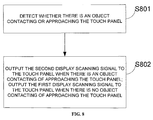
- Fig. 8 is a flow chart showing a driving method according to an embodiment of the present disclosure. This method comprises:
- specific embodiments of the present disclosure enable the touch scanning of the touch device which uses the In-Cell touch technology to operate during the touch event, thereby resolving the conflict that the display scanning and the touch scanning of the touch device using the In-Cell touch technology should be performed in a time-sharing manner. In this way, the touch device is enabled to operate at a higher display refresh rate when there is no touch.
Landscapes
- Engineering & Computer Science (AREA)
- General Engineering & Computer Science (AREA)
- Theoretical Computer Science (AREA)
- Physics & Mathematics (AREA)
- Human Computer Interaction (AREA)
- General Physics & Mathematics (AREA)
- Acoustics & Sound (AREA)
- Position Input By Displaying (AREA)
Abstract
Description
- This application claims priority to the Chinese Application No.
201410258784.8, filed on June 11, 2014 - The present disclosure relates to the field of display technology, and in particular, to a touch device and a method for driving the same.
- As compared with an Out-Cell capacitive touch screen structure, a touch substrate may be omitted from a capacitive touch screen by using the In-Cell touch technology, such that the whole display module may be manufactured in a thinner way. A structural diagram of a liquid crystal display screen using the In-Cell touch technology is shown as
Fig. 1 in which touch driving electrodes (Tx) and touch sensing electrodes (Rx) are manufactured on a glass substrate on an array substrate side of the liquid crystal display panel. The Tx lines share same lines with common electrodes (Vcom) lines. Various parasitic capacitances and coupling capacitances may occur in the liquid crystal display screen (i.e. the capacitive touch screen) using the In-Cell touch technology between the Tx and Rx and the Thin Film Transistor (TFT) display devices. In the figure, each of Gate1, Gate2, ..., Gate n denotes a gate scan line for each line of pixels, respectively; each of Data1, Data2, ..., Data n denotes a data scan line for each line of pixels, respectively; CLC denotes a capacitance between the liquid crystal display panels; and Cs denotes a storage capacitance. -
Fig. 2(a) shows an example of timings for display scanning and touch scanning of an Out-Cell capacitive touch screen, in which al - a60 denote periods for display scanning and t1-t60 denote periods for touch scanning. As shown inFig. 2(a) , for an Out-Cell capacitive touch screen, the touch scanning is performed in synchronization with the picture refresh since the Out-Cell capacitive touch screen is not affected by TFT driving signals. In other words, the display scanning and touch scanning for a capacitive touch screen are performed in synchronization and they are not affected by each other. As shown, the scanning frequency for the display scanning is 60 Hz, and the scanning frequency for the touch scanning is 100 Hz.Fig. 2(b) shows an example of timings for display scanning and touch scanning of a capacitive touch screen using the In-Cell touch technology, in which a1 - a60 denote periods for display scanning and t1-t60 denote periods for touch scanning. As shown inFig. 2(b) , the In-Cell touch technology utilizes a scanning mode in which the scanning is performed in a blank interval between two frames of pictures. In other words, the display scanning and touch scanning for the liquid crystal display screen shall be performed in a time-sharing manner. As shown, the scanning frequency for the display scanning is 40 Hz, and the scanning frequency for the touch scanning is 40 Hz. - A system block diagram of a liquid crystal display screen using the In-Cell touch technology is shown as
Fig. 3 . Touch scanning time, t, assigned to each frame is limited due to the limitation of data transmission rates of the timing controller and driver and charging time of sub-pixels. When t is small, scannings of Tx and Rx cannot be finished, and therefore t is to be increased appropriately. Currently, the direct way to increase t is to increase the scanning time of a frame, and the assigned touch scanning time is increased accordingly. However, this will lead to a lower frame rate, and the quality of the picture will be deteriorated. Flickering, smearing, or the like will occur. - In summary, since a liquid crystal display screen using the In-Cell touch technology utilizes a time-sharing driving method, the liquid crystal display screen cannot operate at a higher display refresh rate when there is no touch.
- Embodiments of the present disclosure provide a touch device and a method for driving the same which is capable of enabling the touch device to operate at a higher display refresh rate when there is no touch and improving the display effect.
- An embodiment of the present disclosure provides a touch device comprising: a touch panel configured to display content, to refresh the displayed content according to a display scanning signal, and capable of sensing a touch on the touch panel and cooperating with a touch controller to scan the touch; a timing controller configured to output the display scanning signal to the touch panel; the touch controller configured to scan and locate the touch on the touch panel; a sensor configured to detect whether there is an object contacting or approaching the touch panel and to output a first indication signal if there is no object contacting or approaching the touch panel and a second indication signal if there is an object contacting or approaching the touch panel; and a controller configured to control the timing controller to output a first display scanning signal when the first indication signal is received and to control the timing controller to output a second display scanning signal when the second indication signal is received, wherein the scanning frequency of the first display scanning signal is higher than that of the second display scanning signal.
- According to an embodiment of the present disclosure, the controller is further configured to: control the touch controller to not operate when the first indication signal is received; and control the touch controller to begin operating when the second indication signal is received.
- The touch device according to an embodiment of the present disclosure has a timing controller that outputs different display scanning signals when there is a touch on the touch panel and when there is no touch on the touch panel. Further, when there is no touch, the touch controller does not operate. Therefore, the touch device provided by an embodiment of the present disclosure may operate at a higher display refresh rate when there is no touch, thereby improving display effect and reducing power consumption.
- According to an embodiment of the present disclosure, the sensor comprises transmitters and receivers, wherein the transmitters are configured to transmit light wave or sound wave towards proximity of the touch panel; and the receivers are configured to receive the light wave or the sound wave and determine whether there is an object contacting or approaching the touch panel based on the change in the light wave or sound wave.
- In this way, when the sensor comprises the transmitters and the receivers, it is more convenient and simpler to detect whether there is an object contacting or approaching the touch panel in practice.
- According to an embodiment of the present disclosure, the number of the transmitters is equal to that of the receivers.
- In this way, by setting the number of transmitters and the number of the receivers to be equal, it is more convenient and simpler in practice.
- According to an embodiment of the present disclosure, the transmitters are located in four corner areas of the touch panel.
- In this way, by disposing the transmitters in the four corner areas of the touch panel, it is more convenient and simpler in practice.
- According to an embodiment of the present disclosure, the number of the transmitters is two.
- In this way, by setting the number of transmitters to be two, it is more convenient and simpler and cost-efficient in practice.
- According to an embodiment of the present disclosure, the transmitters are ultrasonic transmitters or infrared transmitters.
- In this way, when the transmitters are ultrasonic transmitters or infrared transmitters, the principles are simple and stable in practice.
- According to an embodiment of the present disclosure, the receivers are located in four corner areas of the touch panel.
- In this way, by disposing the receivers in the four corner areas of the touch panel, it is more convenient and simpler in practice.
- According to an embodiment of the present disclosure, the receivers are ultrasonic receivers or infrared receivers.
- In this way, when the receivers are ultrasonic receivers or infrared receivers, the principles are simple and stable in practice.
- An embodiment of the present disclosure further provides a method for driving a touch device, comprising: detecting whether there is an object contacting or approaching a touch panel of the touch device, wherein the touch panel is configured to display content, to refresh the displayed content according to a display scanning signal, and is capable of sensing a touch on the touch panel and cooperating with a touch controller to scan the touch; outputting a second display scanning signal to the touch panel if there is an object contacting or approaching the touch panel; and outputting a first display scanning signal to the touch panel if there is no object contacting or approaching the touch panel, wherein the scanning frequency of the first display scanning signal is higher than that of the second display scanning signal.
- According to an embodiment of the present disclosure, the method for driving further comprises: controlling the touch controller to not operate when the first indication signal is received; and controlling the touch controller to begin operating when the second indication signal is received.
- The method for driving a touch device according to an embodiment of the present disclosure outputs different display scanning signals to the touch panel when there is a touch on the touch panel and when there is no touch on the touch panel. Further, when there is no touch, the touch controller does not operate. Therefore, the method for driving provided by an embodiment of the present disclosure may enable the touch device to operate at a higher display refresh rate when there is no touch, thereby reducing power consumption of the touch device.
- According to an embodiment of the present disclosure, the detecting of whether there is an object contacting or approaching a touch panel of the touch device further comprises: transmitting light wave or sound wave towards proximity of the touch panel; and receiving the light wave or the sound wave and determining whether there is an object contacting or approaching the touch panel based on the change in the light wave or sound wave.
- In this way, by using the light wave or the sound wave, it is more convenient and simpler to detect whether there is an object contacting or approaching the touch panel in practice.
-
-
Fig. 1 is a diagram of a structure of a liquid crystal display screen using the In-Cell touch technology; -
Fig. 2(a) andFig. 2(b) are diagrams showing operation timings of an Out-Cell capacitive touch screen and a liquid crystal display screen using the In-Cell touch technology, respectively; -
Fig. 3 is a systematic block diagram of a liquid crystal display screen using the In-Cell touch technology; -
Fig. 4 is a diagram of a touch device according to an embodiment of the present disclosure; -
Fig. 5 is a diagram showing positions of transmitters and receivers in a touch device according to an embodiment of the present disclosure; -
Fig. 6 is a flow chart of operations for a touch device according to an embodiment of the present disclosure; -
Fig. 7 is a timing diagram showing operations of a touch panel when there is a touch and when there is no touch according to an embodiment of the present disclosure; and -
Fig. 8 is a flow chart showing a driving method according to an embodiment of the present disclosure. - Embodiments of the present disclosure provide a touch device and a method for driving the same which enable the touch device to operate at a higher display refresh rate when there is no touch and improve the display effect.
- A touch device and its operations according to an embodiment of the present disclosure will be introduced below in detail with reference to the drawings.
-
Fig. 4 is a diagram showing atouch device 400 according to an embodiment of the present disclosure. As shown inFig. 4 , thetouch device 400 according to the embodiment of the present disclosure comprises: atouch panel 40, atiming controller 41, atouch controller 42, acontroller 43, and asensor 44. Thetouch panel 40 displays content, refreshes the displayed content according to a display scanning signal, and is capable of sensing a touch on thetouch panel 40 and cooperating with thetouch controller 42 to scan the touch. Thetiming controller 41 is configured to output the display scanning signal to thetouch panel 40. Thetouch controller 42 is configured to scan and locate the touch on thetouch panel 40. - The
sensor 44 is configured to detect whether there is an object contacting or approaching thetouch panel 40, and output a first indication signal to thecontroller 43 when there is no object contacting or approaching thetouch panel 40 and a second indication signal to thecontroller 43 when there is an object contacting or approaching thetouch panel 40. - When the first indication signal is received from the
sensor 44, thecontroller 43 controls thetiming controller 41 to output a first display scanning signal to thetouch panel 40; and when the second indication signal is received from thesensor 44, thecontroller 43 controls thetiming controller 41 to output a second display scanning signal to thetouch panel 40. - The scanning frequency of the first display scanning signal is higher than that of the second display scanning signal.
- When the first indication signal is received, the
controller 43 further controls thetouch controller 42 to not operate, and when the second indication signal is received, thecontroller 43 controls thetouch controller 42 to begin operating. - The first and second indication signals output by the
sensor 44 may be a low level signal and a high level signal, and may also be digital signals. - To be specific, an example where the first indication signal is a high level signal and the second indication signal is a low level signal is given. When there is no object contacting or approaching the
touch panel 40, thesensor 44 outputs a high level signal, and transmits the signal to thecontroller 43. Thecontroller 43 in turn controls thetouch controller 42 to not operate, and controls thetiming controller 41 to output the first display scanning signal. When there is an object contacting or approaching thetouch panel 40, thesensor 44 outputs a low level signal, and transmits the signal to thecontroller 43. Thecontroller 43 in turn controls thetiming controller 41 to output the second display scanning signal, and controls thetouch controller 42 to begin operating. That is, thetouch controller 42 begins to scan and locate the touch on thetouch panel 40. - To be specific, the
controller 43 may be an integrated circuit disposed directly in the touch panel or an integrated circuit disposed in a Flexible Printed Circuit (FPC). Further, it can also be disposed at other locations, and no limitation is imposed to its position in the embodiments of the present disclosure. - The
sensor 44 in the embodiment of the present disclosure comprisestransmitters 51 andreceivers 52.Fig. 5 is a diagram showing positions oftransmitters 51 andreceivers 52 in a touch device according to an embodiment of the present disclosure. - The
transmitters 51 are configured to transmit a light wave or a sound wave towards proximity of thetouch panel 40. - The
receivers 52 are configured to receive the light wave or the sound wave, and determine whether there is an object contacting or approaching the touch panel based on the change in the light wave or the sound wave. - To be specific, in an embodiment of the present disclosure, the number of the
transmitters 51 is equal to that of the receives 52. In the embodiment of the present disclosure, the number oftransmitters 51 is two, and thetransmitters 51 are located at the bottom left corner and bottom right corner of thetouch panel 40, respectively. Of course, the transmitters may also be located at the top left corner and top right corner of thetouch panel 40, respectively. There is no limitation to the number and positions of the transmitters in the embodiments of the present disclosure. In an embodiment of the present disclosure, the transmitters may be ultrasonic transmitters or infrared transmitters. Also, there is no limitation to the type of the transmitters in the embodiments of the present disclosure. The transmitters may be other types of sensors, such as, laser transmitters, or the like. In an embodiment of the present disclosure, the number of thereceivers 52 is two, and thereceivers 52 are located at the top left corner and top right corner of thetouch panel 40, respectively. Of course, the receivers may also be located at the bottom left corner and bottom right corner of thetouch panel 40, respectively. There is no limitation imposed to the number and positions of the receivers in the embodiments of the present disclosure. In an embodiment of the present disclosure, the receivers may be ultrasonic receivers or infrared receivers. Also, there is no limitation to the type of the receivers in the embodiments of the present disclosure. The receivers may be other types of sensors, such as, laser receivers, or the like. - To be specific, with reference to
Fig. 6 , an operational process of a touch device according to an embodiment of the present disclosure will be described. As shown inFig. 6 , at the outset, the system is initialized. After the initialization, thetiming controller 41 outputs the first display scanning signal to thetouch panel 40 for scanning and thetouch controller 42 does not operate. Under the control of the first display scanning signal, the touch panel (for example, a liquid crystal display screen) operates at a normal display scanning frequency; meanwhile, thetransmitters 51 located at the bottom left corner and the bottom right corner of thetouch panel 40 begin scanning to transmit light waves or sound waves. When thetransmitters 51 are ultrasonic transmitters, the ultrasonic waves are transmitted. When thetransmitters 51 are infrared transmitters, the infrared waves are transmitted. At the same time, thereceivers 52 located at the top left corner and the top right corner of thetouch panel 40 begin scanning to receive the light waves or sound waves transmitted by thetransmitters 51, and determine whether there is an object contacting or approaching the touch panel based on the change in the light wave or the sound wave. When there is no object contacting or approaching the touch panel, the first indication signal is output to thecontroller 43; and when there is an object contacting or approaching the touch panel, the second indication signal is output to thecontroller 43. If the received light wave or sound wave is not changed, then it can be determined that no object is contacting or approaching the touch panel. At this time, thecontroller 43 controls thetiming controller 41 to keep outputting the first display scanning signal and also controls thetouch controller 42 to not operate. If the received light wave or sound wave is changed, then it can be determined that there is an object contacting or approaching the touch panel. At this time, thecontroller 43 controls thetiming controller 41 to output the second display scanning signal and also controls thetouch controller 42 to begin operating. In this way, the display scanning and the touch scanning for thetouch panel 40 are driven in a time-sharing manner. The specific operations and methods for a time-sharing driving are same as those in the related art, and description thereof will be omitted for simplicity. - To be specific, in an embodiment of the present disclosure, when there is an object contacting or approaching the touch panel, it will be determined that there is a touch on the touch panel. Accordingly, the light wave or sound wave transmitted by the
transmitters 51 are used for sensing the contacting or approaching of the touch panel. Herein, "the proximity of the touch panel" refers to a range in which the transmitted light wave or sound wave can be sensed, and it can be set as required.Fig. 7 is a timing diagram showing operations of a touch panel when there is a touch and when there is no touch according to an embodiment of the present disclosure. As shown inFig. 7 , an example of the ultrasonic wave is used to illustrate the timing of the operations of the touch device according to an embodiment of the present disclosure. When there is no object contacting or approaching the surface of the touch panel, thetiming controller 41 outputs the first display scanning signal and controls the touch panel to operate at a normal display scanning frequency. For example, in a specific embodiment of the present disclosure, the display scanning frequency is 60 Hz, and at this time thetouch controller 42 does not operate. When there is an object contacting or approaching the surface of the touch panel, the ultrasonic wave transmitted by the ultrasonic transmitters will be interfered. At this time, it can be determined by the receivers that there is an object contacting of approaching the surface of the touch panel by analyzing the received ultrasonic waves. When the receivers determine that there is an object contacting or approaching the surface of the touch panels, thecontroller 43 controls thetouch controller 42 to begin operating, and controls thetiming controller 41 to output the second display scanning signal simultaneously. Since the scanning frequency of the first display scanning signal is higher than that of the second display scanning signal in an embodiment of the present disclosure, the display scanning frequency of the touch panel is lowered at this time. In this way, it ensures thetouch controller 42 enough time for scanning, thereby achieving the time-sharing driving of the display scanning and the touch scanning for the touch panel. For example, in a specific embodiment of the present disclosure, the display scanning frequency is 40 Hz, and the touch scanning frequency is 40 Hz. When the receives determine that there is no object contacting or approaching the surface of the touch panel, thecontroller 43 controls thetouch controller 42 to stop operating, and controls thetiming controller 41 to output the first display scanning signal simultaneously. At this time, the touch panel operates at a normal display scanning frequency. For example, in a specific embodiment of the present disclosure, the display scanning frequency is 60 Hz. -
Fig. 8 is a flow chart showing a driving method according to an embodiment of the present disclosure. This method comprises: - S801: whether there is an object contacting or approaching the touch panel is detected.
- S802: If there is an object contacting or approaching the touch panel, the second display scanning signal is output to the touch panel, and if there is no object contacting or approaching the touch panel, the first display scanning signal is output to the touch panel. The scanning frequency of the first display scanning signal is higher than that of the second display scanning signal.
- In summary, by adding sensors and controllers to a touch device which uses the In-Cell touch technology, specific embodiments of the present disclosure enable the touch scanning of the touch device which uses the In-Cell touch technology to operate during the touch event, thereby resolving the conflict that the display scanning and the touch scanning of the touch device using the In-Cell touch technology should be performed in a time-sharing manner. In this way, the touch device is enabled to operate at a higher display refresh rate when there is no touch.
- Obviously, one skilled in the art may make various changes and variations of the present disclosure without departing from the spirit and scope of the present disclosure. In this way, if the changes and variations of the present disclosure fall into the scope of the claims of the present application and the full equivalents thereof, then the present disclosure is intended to cover such changes and variations.
Claims (12)
- A touch device comprising:a touch panel configured to display content, to refresh the displayed content according to a display scanning signal, and capable of sensing a touch on the touch panel and cooperating with a touch controller to scan the touch;a timing controller configured to output the display scanning signal to the touch panel;the touch controller configured to scan and locate the touch on the touch panel;a sensor configured to detect whether there is an object contacting or approaching the touch panel, and to output a first indication signal if there is no object contacting or approaching the touch panel and a second indication signal if there is an object contacting or approaching the touch panel; anda controller configured to control the timing controller to output a first display scanning signal when the first indication signal is received and to control the timing controller to output a second display scanning signal when the second indication signal is received,wherein the scanning frequency of the first display scanning signal is higher than that of the second display scanning signal.
- The touch device according to Claim 1, wherein the controller is further configured to:control the touch controller to not operate when the first indication signal is received; andcontrol the touch controller to begin operating when the second indication signal is received.
- The touch device according to Claim 1, wherein the sensor comprises transmitters and receivers, and wherein
the transmitters are configured to transmit light waves or sound waves towards proximity of the touch panel; and
the receivers are configured to receive the light waves or the sound waves and determine whether there is an object contacting or approaching the touch panel based on the change in the light waves or sound waves. - The touch device according to Claim 3, wherein the number of the transmitters is equal to that of the receivers.
- The touch device according to Claim 4, wherein the transmitters are located in four corner areas of the touch panel.
- The touch device according to Claim 5, wherein the number of the transmitters is two.
- The touch device according to Claim 6, wherein the transmitters are ultrasonic transmitters or infrared transmitters.
- The touch device according to Claim 4, wherein the receivers are located in four comer areas of the touch panel.
- The touch device according to Claim 8, wherein the receivers are ultrasonic receivers or infrared receivers.
- A method for driving a touch device, comprising:detecting whether there is an object contacting or approaching a touch panel of the touch device, wherein the touch panel is configured to display content, to refresh the displayed content according to a display scanning signal, and is capable of sensing a touch on the touch panel and cooperating with a touch controller to scan the touch;outputting a second display scanning signal to the touch panel if there is an object contacting or approaching the touch panel; andoutputting a first display scanning signal to the touch panel if there is no object contacting or approaching the touch panel,wherein the scanning frequency of the first display scanning signal is higher than that of the second display scanning signal.
- The method for driving according to Claim 10, further comprising:controlling the touch controller to not operate when the first indication signal is received; andcontrolling the touch controller to begin operating when the second indication signal is received.
- The method for driving according to Claim 10, wherein the detecting of whether there is an object contacting or approaching a touch panel of the touch device further comprises:transmitting light waves or sound waves towards proximity of the touch panel; andreceiving the light waves or the sound waves and determining whether there is an object contacting or approaching the touch panel based on the change in the light wave or sound wave.
Applications Claiming Priority (2)
| Application Number | Priority Date | Filing Date | Title |
|---|---|---|---|
| CN201410258784.8A CN104063105B (en) | 2014-06-11 | 2014-06-11 | Touch device and touch driving method |
| PCT/CN2014/086120 WO2015188477A1 (en) | 2014-06-11 | 2014-09-09 | Touch device and driving method |
Publications (3)
| Publication Number | Publication Date |
|---|---|
| EP3065037A1 true EP3065037A1 (en) | 2016-09-07 |
| EP3065037A4 EP3065037A4 (en) | 2017-01-11 |
| EP3065037B1 EP3065037B1 (en) | 2020-01-22 |
Family
ID=51550846
Family Applications (1)
| Application Number | Title | Priority Date | Filing Date |
|---|---|---|---|
| EP14882147.3A Active EP3065037B1 (en) | 2014-06-11 | 2014-09-09 | Touch device and driving method |
Country Status (4)
| Country | Link |
|---|---|
| US (1) | US9696846B2 (en) |
| EP (1) | EP3065037B1 (en) |
| CN (1) | CN104063105B (en) |
| WO (1) | WO2015188477A1 (en) |
Families Citing this family (20)
| Publication number | Priority date | Publication date | Assignee | Title |
|---|---|---|---|---|
| US10275070B2 (en) * | 2015-01-05 | 2019-04-30 | Synaptics Incorporated | Time sharing of display and sensing data |
| CN104991675B (en) * | 2015-07-17 | 2018-01-09 | 京东方科技集团股份有限公司 | touch display drive method, drive module and display device |
| CN104991682B (en) * | 2015-08-07 | 2017-11-14 | 京东方科技集团股份有限公司 | A kind of touch-control driving method, touch-control drive device and touch control display apparatus |
| CN105204703B (en) | 2015-10-10 | 2018-06-29 | 重庆京东方光电科技有限公司 | A kind of touch detecting method and equipment for touch display screen |
| CN105892766A (en) * | 2016-06-28 | 2016-08-24 | 广州华欣电子科技有限公司 | Operating mode control method and operating mode control device of infrared touch frame |
| US10133403B2 (en) * | 2016-06-29 | 2018-11-20 | Apple Inc. | System and method for variable frame duration control in an electronic display |
| CN107016963A (en) * | 2017-04-20 | 2017-08-04 | 京东方科技集团股份有限公司 | The driving method of electroluminescence display panel, its drive device and display device |
| US10444907B2 (en) * | 2017-05-16 | 2019-10-15 | Honeywell International Inc. | Devices and methods for using an infrared-projected capacitive (IR-PCAP) touchscreen |
| CN108108074A (en) * | 2018-01-26 | 2018-06-01 | 江西合力泰科技有限公司 | A kind of large scale self-capacitance touch-control film and its application |
| CN108762544A (en) * | 2018-04-25 | 2018-11-06 | 维沃移动通信有限公司 | The control method of a kind of electronic equipment and touching display screen |
| CN109144359A (en) * | 2018-06-27 | 2019-01-04 | 努比亚技术有限公司 | A kind of screen parameter control method, terminal and computer readable storage medium |
| CN109240537B (en) * | 2018-08-23 | 2021-03-09 | 硅谷数模半导体(北京)有限公司 | Control method, device and equipment of touch screen, storage medium and processor |
| CN109002226A (en) * | 2018-09-26 | 2018-12-14 | 舒伟 | touch device, control method, device and display system |
| KR102483342B1 (en) * | 2018-11-02 | 2022-12-30 | 엘지디스플레이 주식회사 | Ultrasonic sensor, ultrasonic sensing device, display device and biometric data sensing method |
| CN111610872B (en) * | 2019-02-26 | 2023-07-07 | 敦泰电子有限公司 | Touch control method, circuit system and touch device |
| CN114253411B (en) * | 2020-09-21 | 2024-04-16 | 京东方科技集团股份有限公司 | Driving method and circuit of touch display substrate, device and display device |
| CN116247766A (en) * | 2021-03-15 | 2023-06-09 | 荣耀终端有限公司 | Wireless charging system, chip and wireless charging circuit |
| CN118076996A (en) | 2022-09-23 | 2024-05-24 | 京东方科技集团股份有限公司 | Display device, gamma voltage data group switching method and module |
| CN116719439B (en) * | 2022-09-27 | 2024-06-11 | 广州众远智慧科技有限公司 | Infrared signal scanning method and device |
| CN116343640B (en) * | 2023-03-28 | 2026-01-23 | 福州京东方光电科技有限公司 | Display device and driving method thereof |
Family Cites Families (16)
| Publication number | Priority date | Publication date | Assignee | Title |
|---|---|---|---|---|
| CN101866210B (en) * | 2009-04-16 | 2012-03-21 | 群康科技(深圳)有限公司 | Power saving device and method for capacitive touch pad and capacitive touch pad |
| US8576161B2 (en) | 2009-06-18 | 2013-11-05 | Apple Inc. | Driving an OLED display structure integrated with a touch sensor configuration |
| CN101833420B (en) | 2010-05-19 | 2012-08-29 | 鸿富锦精密工业(深圳)有限公司 | Electronic device with touch panel |
| JP5501158B2 (en) * | 2010-08-23 | 2014-05-21 | 株式会社ジャパンディスプレイ | Display device with touch detection function, drive circuit, driving method of display device with touch detection function, and electronic device |
| US8866783B2 (en) | 2011-04-08 | 2014-10-21 | Sharp Kabushiki Kaisha | Display device, method for driving same, and electronic apparatus |
| JP5280596B2 (en) | 2011-04-15 | 2013-09-04 | シャープ株式会社 | Display device, display device driving method, and electronic apparatus |
| CN102999212B (en) * | 2011-09-16 | 2016-08-03 | 宏达国际电子股份有限公司 | Electronic device |
| US9099971B2 (en) | 2011-11-18 | 2015-08-04 | Sentons Inc. | Virtual keyboard interaction using touch input force |
| US8952936B2 (en) | 2012-04-02 | 2015-02-10 | Egalax—Empia Technology Inc. | Method and device for position detection |
| CN103279214A (en) * | 2012-06-28 | 2013-09-04 | 上海天马微电子有限公司 | Driving method of touch display screen |
| TWI475441B (en) | 2012-10-19 | 2015-03-01 | Au Optronics Corp | In-cell touch display panel and driving method thereof |
| KR102050385B1 (en) | 2012-10-30 | 2019-11-29 | 엘지디스플레이 주식회사 | Touch sensing system and method of reducing latency thereof |
| TWI602089B (en) * | 2012-12-05 | 2017-10-11 | 日本顯示器股份有限公司 | Display device with touch detection function, drive method thereof, and electronic apparatus |
| CN103186426A (en) | 2012-12-21 | 2013-07-03 | 敦泰科技有限公司 | Method for preventing touch detection and LCD (liquid crystal display) scan from mutual interference |
| CN103151019B (en) | 2013-01-28 | 2015-06-03 | 广东欧珀移动通信有限公司 | Control method and control device for display refresh rate of mobile terminal |
| CN103149723B (en) * | 2013-03-20 | 2016-02-03 | 敦泰电子有限公司 | The touch control method of liquid crystal indicator and can touch control liquid crystal display device |
-
2014
- 2014-06-11 CN CN201410258784.8A patent/CN104063105B/en not_active Expired - Fee Related
- 2014-09-09 US US14/769,143 patent/US9696846B2/en not_active Expired - Fee Related
- 2014-09-09 EP EP14882147.3A patent/EP3065037B1/en active Active
- 2014-09-09 WO PCT/CN2014/086120 patent/WO2015188477A1/en not_active Ceased
Also Published As
| Publication number | Publication date |
|---|---|
| EP3065037A4 (en) | 2017-01-11 |
| EP3065037B1 (en) | 2020-01-22 |
| CN104063105A (en) | 2014-09-24 |
| WO2015188477A1 (en) | 2015-12-17 |
| US20160246431A1 (en) | 2016-08-25 |
| CN104063105B (en) | 2017-02-15 |
| US9696846B2 (en) | 2017-07-04 |
Similar Documents
| Publication | Publication Date | Title |
|---|---|---|
| EP3065037B1 (en) | Touch device and driving method | |
| KR102460552B1 (en) | Touch display device, display controller, driving circuit, and driving method | |
| TWI502441B (en) | Touch display device and method | |
| US10528183B2 (en) | Touch display device | |
| KR102260600B1 (en) | Touch screen device | |
| KR101401254B1 (en) | Liquid crystal display and method of driving the same | |
| US9335861B2 (en) | Touch sensing system and driving method thereof, and display device using the touch sensing system | |
| KR101623776B1 (en) | Touch display driver integrated circuit and touch display device | |
| US10067605B2 (en) | Driving method for reducing display interference in in-cell multi-touch panel and system using the same | |
| US20120056834A1 (en) | Display Device Having Touch Sensor and Method for Driving the Same | |
| KR101461036B1 (en) | Apparatus and method for driving touch sensor | |
| CN108664163A (en) | Control method and touch display system | |
| CN103383613A (en) | Touch screen driver | |
| KR20160012487A (en) | Display device having touch panel | |
| KR102257980B1 (en) | Touch screen device | |
| CN109828686B (en) | Control method and control device of touch display screen | |
| KR102595502B1 (en) | Touch panel and inspection method of thereof, and liquid crystal display device having touch panel | |
| US9811190B2 (en) | Display driving method and apparatus for in-cell touch display screen, and display apparatus | |
| KR102071204B1 (en) | Touch Display Device And Method Of Driving The Same | |
| KR20140044688A (en) | Apparatus and method for driving touch sensor | |
| KR20160094541A (en) | Display device and method of driving the same | |
| US11907453B2 (en) | Devices and methods for controlling proximity sensing in input-display device | |
| US20190235607A1 (en) | Display device with built-in touch panel | |
| KR101970549B1 (en) | Apparatus for driving touch sensor | |
| KR102506658B1 (en) | Touch screen device and its driving method |
Legal Events
| Date | Code | Title | Description |
|---|---|---|---|
| PUAI | Public reference made under article 153(3) epc to a published international application that has entered the european phase |
Free format text: ORIGINAL CODE: 0009012 |
|
| 17P | Request for examination filed |
Effective date: 20150819 |
|
| AK | Designated contracting states |
Kind code of ref document: A1 Designated state(s): AL AT BE BG CH CY CZ DE DK EE ES FI FR GB GR HR HU IE IS IT LI LT LU LV MC MK MT NL NO PL PT RO RS SE SI SK SM TR |
|
| AX | Request for extension of the european patent |
Extension state: BA ME |
|
| RIC1 | Information provided on ipc code assigned before grant |
Ipc: G06F 3/044 20060101AFI20161004BHEP |
|
| RIN1 | Information on inventor provided before grant (corrected) |
Inventor name: MA, TAO Inventor name: ZHANG, DAYU |
|
| A4 | Supplementary search report drawn up and despatched |
Effective date: 20161209 |
|
| RIC1 | Information provided on ipc code assigned before grant |
Ipc: G06F 3/043 20060101ALI20161205BHEP Ipc: G06F 3/042 20060101ALI20161205BHEP Ipc: G06F 3/044 20060101AFI20161205BHEP |
|
| RIC1 | Information provided on ipc code assigned before grant |
Ipc: G06F 3/042 20060101ALI20170104BHEP Ipc: G06F 3/043 20060101ALI20170104BHEP Ipc: G06F 3/044 20060101AFI20170104BHEP |
|
| DAX | Request for extension of the european patent (deleted) | ||
| REG | Reference to a national code |
Ref country code: DE Ref legal event code: R079 Ref document number: 602014060506 Country of ref document: DE Free format text: PREVIOUS MAIN CLASS: G06F0003044000 Ipc: G06F0003041000 |
|
| GRAP | Despatch of communication of intention to grant a patent |
Free format text: ORIGINAL CODE: EPIDOSNIGR1 |
|
| STAA | Information on the status of an ep patent application or granted ep patent |
Free format text: STATUS: GRANT OF PATENT IS INTENDED |
|
| RIC1 | Information provided on ipc code assigned before grant |
Ipc: G06F 3/042 20060101ALI20190807BHEP Ipc: G06F 3/041 20060101AFI20190807BHEP Ipc: G06F 3/044 20060101ALI20190807BHEP Ipc: G06F 3/043 20060101ALI20190807BHEP |
|
| RAP1 | Party data changed (applicant data changed or rights of an application transferred) |
Owner name: BOE TECHNOLOGY GROUP CO., LTD. Owner name: HEFEI XINSHENG OPTOELECTRONICS TECHNOLOGY CO., LTD |
|
| INTG | Intention to grant announced |
Effective date: 20190904 |
|
| GRAS | Grant fee paid |
Free format text: ORIGINAL CODE: EPIDOSNIGR3 |
|
| GRAA | (expected) grant |
Free format text: ORIGINAL CODE: 0009210 |
|
| STAA | Information on the status of an ep patent application or granted ep patent |
Free format text: STATUS: THE PATENT HAS BEEN GRANTED |
|
| AK | Designated contracting states |
Kind code of ref document: B1 Designated state(s): AL AT BE BG CH CY CZ DE DK EE ES FI FR GB GR HR HU IE IS IT LI LT LU LV MC MK MT NL NO PL PT RO RS SE SI SK SM TR |
|
| REG | Reference to a national code |
Ref country code: GB Ref legal event code: FG4D |
|
| REG | Reference to a national code |
Ref country code: CH Ref legal event code: EP |
|
| REG | Reference to a national code |
Ref country code: AT Ref legal event code: REF Ref document number: 1227333 Country of ref document: AT Kind code of ref document: T Effective date: 20200215 |
|
| REG | Reference to a national code |
Ref country code: IE Ref legal event code: FG4D |
|
| REG | Reference to a national code |
Ref country code: DE Ref legal event code: R096 Ref document number: 602014060506 Country of ref document: DE |
|
| REG | Reference to a national code |
Ref country code: NL Ref legal event code: MP Effective date: 20200122 |
|
| REG | Reference to a national code |
Ref country code: LT Ref legal event code: MG4D |
|
| PG25 | Lapsed in a contracting state [announced via postgrant information from national office to epo] |
Ref country code: RS Free format text: LAPSE BECAUSE OF FAILURE TO SUBMIT A TRANSLATION OF THE DESCRIPTION OR TO PAY THE FEE WITHIN THE PRESCRIBED TIME-LIMIT Effective date: 20200122 Ref country code: PT Free format text: LAPSE BECAUSE OF FAILURE TO SUBMIT A TRANSLATION OF THE DESCRIPTION OR TO PAY THE FEE WITHIN THE PRESCRIBED TIME-LIMIT Effective date: 20200614 Ref country code: NL Free format text: LAPSE BECAUSE OF FAILURE TO SUBMIT A TRANSLATION OF THE DESCRIPTION OR TO PAY THE FEE WITHIN THE PRESCRIBED TIME-LIMIT Effective date: 20200122 Ref country code: NO Free format text: LAPSE BECAUSE OF FAILURE TO SUBMIT A TRANSLATION OF THE DESCRIPTION OR TO PAY THE FEE WITHIN THE PRESCRIBED TIME-LIMIT Effective date: 20200422 Ref country code: FI Free format text: LAPSE BECAUSE OF FAILURE TO SUBMIT A TRANSLATION OF THE DESCRIPTION OR TO PAY THE FEE WITHIN THE PRESCRIBED TIME-LIMIT Effective date: 20200122 |
|
| PG25 | Lapsed in a contracting state [announced via postgrant information from national office to epo] |
Ref country code: IS Free format text: LAPSE BECAUSE OF FAILURE TO SUBMIT A TRANSLATION OF THE DESCRIPTION OR TO PAY THE FEE WITHIN THE PRESCRIBED TIME-LIMIT Effective date: 20200522 Ref country code: GR Free format text: LAPSE BECAUSE OF FAILURE TO SUBMIT A TRANSLATION OF THE DESCRIPTION OR TO PAY THE FEE WITHIN THE PRESCRIBED TIME-LIMIT Effective date: 20200423 Ref country code: HR Free format text: LAPSE BECAUSE OF FAILURE TO SUBMIT A TRANSLATION OF THE DESCRIPTION OR TO PAY THE FEE WITHIN THE PRESCRIBED TIME-LIMIT Effective date: 20200122 Ref country code: SE Free format text: LAPSE BECAUSE OF FAILURE TO SUBMIT A TRANSLATION OF THE DESCRIPTION OR TO PAY THE FEE WITHIN THE PRESCRIBED TIME-LIMIT Effective date: 20200122 Ref country code: LV Free format text: LAPSE BECAUSE OF FAILURE TO SUBMIT A TRANSLATION OF THE DESCRIPTION OR TO PAY THE FEE WITHIN THE PRESCRIBED TIME-LIMIT Effective date: 20200122 Ref country code: BG Free format text: LAPSE BECAUSE OF FAILURE TO SUBMIT A TRANSLATION OF THE DESCRIPTION OR TO PAY THE FEE WITHIN THE PRESCRIBED TIME-LIMIT Effective date: 20200422 |
|
| REG | Reference to a national code |
Ref country code: DE Ref legal event code: R097 Ref document number: 602014060506 Country of ref document: DE |
|
| PG25 | Lapsed in a contracting state [announced via postgrant information from national office to epo] |
Ref country code: DK Free format text: LAPSE BECAUSE OF FAILURE TO SUBMIT A TRANSLATION OF THE DESCRIPTION OR TO PAY THE FEE WITHIN THE PRESCRIBED TIME-LIMIT Effective date: 20200122 Ref country code: EE Free format text: LAPSE BECAUSE OF FAILURE TO SUBMIT A TRANSLATION OF THE DESCRIPTION OR TO PAY THE FEE WITHIN THE PRESCRIBED TIME-LIMIT Effective date: 20200122 Ref country code: SM Free format text: LAPSE BECAUSE OF FAILURE TO SUBMIT A TRANSLATION OF THE DESCRIPTION OR TO PAY THE FEE WITHIN THE PRESCRIBED TIME-LIMIT Effective date: 20200122 Ref country code: ES Free format text: LAPSE BECAUSE OF FAILURE TO SUBMIT A TRANSLATION OF THE DESCRIPTION OR TO PAY THE FEE WITHIN THE PRESCRIBED TIME-LIMIT Effective date: 20200122 Ref country code: LT Free format text: LAPSE BECAUSE OF FAILURE TO SUBMIT A TRANSLATION OF THE DESCRIPTION OR TO PAY THE FEE WITHIN THE PRESCRIBED TIME-LIMIT Effective date: 20200122 Ref country code: RO Free format text: LAPSE BECAUSE OF FAILURE TO SUBMIT A TRANSLATION OF THE DESCRIPTION OR TO PAY THE FEE WITHIN THE PRESCRIBED TIME-LIMIT Effective date: 20200122 Ref country code: CZ Free format text: LAPSE BECAUSE OF FAILURE TO SUBMIT A TRANSLATION OF THE DESCRIPTION OR TO PAY THE FEE WITHIN THE PRESCRIBED TIME-LIMIT Effective date: 20200122 Ref country code: SK Free format text: LAPSE BECAUSE OF FAILURE TO SUBMIT A TRANSLATION OF THE DESCRIPTION OR TO PAY THE FEE WITHIN THE PRESCRIBED TIME-LIMIT Effective date: 20200122 |
|
| REG | Reference to a national code |
Ref country code: AT Ref legal event code: MK05 Ref document number: 1227333 Country of ref document: AT Kind code of ref document: T Effective date: 20200122 |
|
| PLBE | No opposition filed within time limit |
Free format text: ORIGINAL CODE: 0009261 |
|
| STAA | Information on the status of an ep patent application or granted ep patent |
Free format text: STATUS: NO OPPOSITION FILED WITHIN TIME LIMIT |
|
| 26N | No opposition filed |
Effective date: 20201023 |
|
| PG25 | Lapsed in a contracting state [announced via postgrant information from national office to epo] |
Ref country code: IT Free format text: LAPSE BECAUSE OF FAILURE TO SUBMIT A TRANSLATION OF THE DESCRIPTION OR TO PAY THE FEE WITHIN THE PRESCRIBED TIME-LIMIT Effective date: 20200122 Ref country code: AT Free format text: LAPSE BECAUSE OF FAILURE TO SUBMIT A TRANSLATION OF THE DESCRIPTION OR TO PAY THE FEE WITHIN THE PRESCRIBED TIME-LIMIT Effective date: 20200122 |
|
| PG25 | Lapsed in a contracting state [announced via postgrant information from national office to epo] |
Ref country code: PL Free format text: LAPSE BECAUSE OF FAILURE TO SUBMIT A TRANSLATION OF THE DESCRIPTION OR TO PAY THE FEE WITHIN THE PRESCRIBED TIME-LIMIT Effective date: 20200122 Ref country code: SI Free format text: LAPSE BECAUSE OF FAILURE TO SUBMIT A TRANSLATION OF THE DESCRIPTION OR TO PAY THE FEE WITHIN THE PRESCRIBED TIME-LIMIT Effective date: 20200122 |
|
| PG25 | Lapsed in a contracting state [announced via postgrant information from national office to epo] |
Ref country code: MC Free format text: LAPSE BECAUSE OF FAILURE TO SUBMIT A TRANSLATION OF THE DESCRIPTION OR TO PAY THE FEE WITHIN THE PRESCRIBED TIME-LIMIT Effective date: 20200122 |
|
| REG | Reference to a national code |
Ref country code: CH Ref legal event code: PL |
|
| GBPC | Gb: european patent ceased through non-payment of renewal fee |
Effective date: 20200909 |
|
| REG | Reference to a national code |
Ref country code: BE Ref legal event code: MM Effective date: 20200930 |
|
| PG25 | Lapsed in a contracting state [announced via postgrant information from national office to epo] |
Ref country code: LU Free format text: LAPSE BECAUSE OF NON-PAYMENT OF DUE FEES Effective date: 20200909 |
|
| PG25 | Lapsed in a contracting state [announced via postgrant information from national office to epo] |
Ref country code: FR Free format text: LAPSE BECAUSE OF NON-PAYMENT OF DUE FEES Effective date: 20200930 |
|
| PG25 | Lapsed in a contracting state [announced via postgrant information from national office to epo] |
Ref country code: GB Free format text: LAPSE BECAUSE OF NON-PAYMENT OF DUE FEES Effective date: 20200909 Ref country code: IE Free format text: LAPSE BECAUSE OF NON-PAYMENT OF DUE FEES Effective date: 20200909 Ref country code: LI Free format text: LAPSE BECAUSE OF NON-PAYMENT OF DUE FEES Effective date: 20200930 Ref country code: BE Free format text: LAPSE BECAUSE OF NON-PAYMENT OF DUE FEES Effective date: 20200930 Ref country code: CH Free format text: LAPSE BECAUSE OF NON-PAYMENT OF DUE FEES Effective date: 20200930 |
|
| PGFP | Annual fee paid to national office [announced via postgrant information from national office to epo] |
Ref country code: DE Payment date: 20210920 Year of fee payment: 8 |
|
| PG25 | Lapsed in a contracting state [announced via postgrant information from national office to epo] |
Ref country code: TR Free format text: LAPSE BECAUSE OF FAILURE TO SUBMIT A TRANSLATION OF THE DESCRIPTION OR TO PAY THE FEE WITHIN THE PRESCRIBED TIME-LIMIT Effective date: 20200122 Ref country code: MT Free format text: LAPSE BECAUSE OF FAILURE TO SUBMIT A TRANSLATION OF THE DESCRIPTION OR TO PAY THE FEE WITHIN THE PRESCRIBED TIME-LIMIT Effective date: 20200122 Ref country code: CY Free format text: LAPSE BECAUSE OF FAILURE TO SUBMIT A TRANSLATION OF THE DESCRIPTION OR TO PAY THE FEE WITHIN THE PRESCRIBED TIME-LIMIT Effective date: 20200122 |
|
| PG25 | Lapsed in a contracting state [announced via postgrant information from national office to epo] |
Ref country code: MK Free format text: LAPSE BECAUSE OF FAILURE TO SUBMIT A TRANSLATION OF THE DESCRIPTION OR TO PAY THE FEE WITHIN THE PRESCRIBED TIME-LIMIT Effective date: 20200122 Ref country code: AL Free format text: LAPSE BECAUSE OF FAILURE TO SUBMIT A TRANSLATION OF THE DESCRIPTION OR TO PAY THE FEE WITHIN THE PRESCRIBED TIME-LIMIT Effective date: 20200122 |
|
| REG | Reference to a national code |
Ref country code: DE Ref legal event code: R119 Ref document number: 602014060506 Country of ref document: DE |
|
| PG25 | Lapsed in a contracting state [announced via postgrant information from national office to epo] |
Ref country code: DE Free format text: LAPSE BECAUSE OF NON-PAYMENT OF DUE FEES Effective date: 20230401 |