EP3064972A1 - Debris-removing cap for optical devices - Google Patents
Debris-removing cap for optical devices Download PDFInfo
- Publication number
- EP3064972A1 EP3064972A1 EP16157219.3A EP16157219A EP3064972A1 EP 3064972 A1 EP3064972 A1 EP 3064972A1 EP 16157219 A EP16157219 A EP 16157219A EP 3064972 A1 EP3064972 A1 EP 3064972A1
- Authority
- EP
- European Patent Office
- Prior art keywords
- debris
- lens
- optical device
- wiper
- cap
- Prior art date
- Legal status (The legal status is an assumption and is not a legal conclusion. Google has not performed a legal analysis and makes no representation as to the accuracy of the status listed.)
- Granted
Links
Images



Classifications
-
- G—PHYSICS
- G02—OPTICS
- G02B—OPTICAL ELEMENTS, SYSTEMS OR APPARATUS
- G02B6/00—Light guides; Structural details of arrangements comprising light guides and other optical elements, e.g. couplings
- G02B6/24—Coupling light guides
- G02B6/36—Mechanical coupling means
- G02B6/38—Mechanical coupling means having fibre to fibre mating means
- G02B6/3807—Dismountable connectors, i.e. comprising plugs
- G02B6/3833—Details of mounting fibres in ferrules; Assembly methods; Manufacture
- G02B6/3847—Details of mounting fibres in ferrules; Assembly methods; Manufacture with means preventing fibre end damage, e.g. recessed fibre surfaces
- G02B6/3849—Details of mounting fibres in ferrules; Assembly methods; Manufacture with means preventing fibre end damage, e.g. recessed fibre surfaces using mechanical protective elements, e.g. caps, hoods, sealing membranes
-
- G—PHYSICS
- G02—OPTICS
- G02B—OPTICAL ELEMENTS, SYSTEMS OR APPARATUS
- G02B6/00—Light guides; Structural details of arrangements comprising light guides and other optical elements, e.g. couplings
- G02B6/24—Coupling light guides
- G02B6/25—Preparing the ends of light guides for coupling, e.g. cutting
-
- G—PHYSICS
- G02—OPTICS
- G02B—OPTICAL ELEMENTS, SYSTEMS OR APPARATUS
- G02B6/00—Light guides; Structural details of arrangements comprising light guides and other optical elements, e.g. couplings
- G02B6/24—Coupling light guides
- G02B6/36—Mechanical coupling means
- G02B6/38—Mechanical coupling means having fibre to fibre mating means
- G02B6/3807—Dismountable connectors, i.e. comprising plugs
- G02B6/3833—Details of mounting fibres in ferrules; Assembly methods; Manufacture
- G02B6/3853—Lens inside the ferrule
-
- G—PHYSICS
- G02—OPTICS
- G02B—OPTICAL ELEMENTS, SYSTEMS OR APPARATUS
- G02B6/00—Light guides; Structural details of arrangements comprising light guides and other optical elements, e.g. couplings
- G02B6/24—Coupling light guides
- G02B6/36—Mechanical coupling means
- G02B6/38—Mechanical coupling means having fibre to fibre mating means
- G02B6/3807—Dismountable connectors, i.e. comprising plugs
- G02B6/3833—Details of mounting fibres in ferrules; Assembly methods; Manufacture
- G02B6/3866—Devices, tools or methods for cleaning connectors
-
- G—PHYSICS
- G02—OPTICS
- G02B—OPTICAL ELEMENTS, SYSTEMS OR APPARATUS
- G02B6/00—Light guides; Structural details of arrangements comprising light guides and other optical elements, e.g. couplings
- G02B6/24—Coupling light guides
- G02B6/36—Mechanical coupling means
- G02B6/38—Mechanical coupling means having fibre to fibre mating means
- G02B6/3807—Dismountable connectors, i.e. comprising plugs
- G02B6/3869—Mounting ferrules to connector body, i.e. plugs
- G02B6/387—Connector plugs comprising two complementary members, e.g. shells, caps, covers, locked together
Definitions
- a single lens wiper is used to wipe the ferrule lens. It is contemplated, however, that embodiments may include more than one lens wiper. It is also contemplated that the debris-removing cap and the optical device will be assembled together as a kit or assembly.
Landscapes
- Physics & Mathematics (AREA)
- General Physics & Mathematics (AREA)
- Optics & Photonics (AREA)
- Optical Couplings Of Light Guides (AREA)
Abstract
Description
- The subject matter herein relates generally to optical devices having exposed lenses.
- Optical communication may have advantages over electrical communication in certain applications. Increasingly, both large communication systems and small devices, such as consumer devices, are using optical pathways to transmit data signals through the system or device. The optical pathways may include optical fibers, lenses, and/or other material that permits light to propagate therethrough. When two optical devices are mated, the optical components (e.g., lenses or fibers) are aligned with each other so that light emitting from one component is received by the other component.
- At least some known optical devices include a ferrule body that optically connects a number of optical fibers to corresponding lenses of a lens array. For example, the ferrule body may include a plurality of channels that each receive and orient a corresponding optical fiber so that the optical fiber is aligned with a corresponding lens of the lens array. The ferrule body may then be positioned adjacent to another optical device. For instance, each lens of the ferrule body may be aligned with another lens and/or optical fiber of the other optical device. Optical devices may be mated with each other in various manners. For some types of optical devices, the lenses face in the direction of insertion. For example, the lenses may be positioned along a side face of a pluggable optical device. In other types of optical devices, however, the lenses may face in a direction that is perpendicular to the insertion direction or perpendicular to the optical fibers.
- One challenge that is often confronted by optical devices is that dust or other debris may exist along the lenses and negatively affect optical transmission. The debris is typically removed using a separate cleaning mechanism. For example, prior to mating the optical devices, a technician may clean each lens array using a tool. Such a cleaning process may be time-consuming and/or labor-intensive and, consequently, expensive.
- Accordingly a need exists for alternative mechanisms or methods of cleaning one or more optical surfaces of an optical connector.
- In an embodiment, a debris-removing cap is provided that includes a cap body having a receiving cavity and an interior surface disposed within the receiving cavity. The cap body is configured to be attached to an optical device such that a mating face of the optical device is disposed within the receiving cavity. The interior surface is configured to face the mating face of the optical device. The debris-removing cap also includes a lens wiper that is coupled to the interior surface within the receiving cavity and extends away from the interior surface toward the mating face of the optical device. The lens wiper moves relative to the mating face when activated by a user of the debris-removing cap. The lens wiper engages a lens of the mating face when activated by the user to remove debris from the lens.
- In an embodiment, a debris-removing cap is provided that includes a cap body having an interior surface that defines a receiving cavity. The cap body is configured to be attached to an optical device such that a mating face of the optical device is disposed within the receiving cavity. The debris-removing cap also includes a lens wiper coupled to the cap body and positioned within the receiving cavity. The lens wiper has an activation surface that is exposed to an exterior of the cap body and is configured to be engaged by a user of the debris-removing cap. The lens wiper engages a lens of the mating face and sweeps across the mating face when activated by the user to remove debris from the lens.
-
-
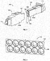
Figure 1 is a perspective view of an optical communication system including a pair of optical cable assemblies. -
Figure 2 is an enlarged perspective view of a lens array that may be used by the optical cable assemblies. -
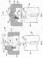
Figure 3 is a side cross-sectional view of a debris-removing cap formed in accordance with an embodiment prior to being coupled onto an end of an optical device. -
Figure 4 is a side cross-sectional view of the debris-removing cap ofFigure 3 prior to being activated by a user for cleaning the mating face of the optical device. -
Figure 5 is a side cross-sectional view of the debris-removing cap ofFigure 3 during activation by a user. -
Figure 6 is a side cross-sectional view of a debris-removing cap formed in accordance with an embodiment. -
Figure 7 is a side cross-sectional view of a debris-removing cap formed in accordance with an embodiment. -
Figure 8 is a side cross-sectional view of a debris-removing cap formed in accordance with an embodiment. -
Figure 9 is a side cross-sectional view of the debris-removing cap ofFigure 8 during activation by a user. - Embodiments set forth herein include debris-removing caps that are configured to interact with an optical device (e.g., a pluggable optical connector) having a mating face that includes a lens. The debris-removing caps include cap bodies tha may be configured to removably attach to the optical device. For example, if the optical device is a pluggable optical connector, the cap body may surround a pluggable end of the optical connector and form an interference fit therewith. The optical device may be received within a receiving cavity that is defined by the cap body. The debris-removing cap may include a lens wiper within the receiving cavity of the cap body. The lens wiper is configured to be activated by a user. More specifically, a force generated by the user may be used to move the lens wiper or translated into a force that moves the lens wiper. The lens wiper may sweep across the mating face and/or the lens of the optical device and thereby clean the lens. The lens wiper may be configured to remove dust, oil, and/or other contaminants.
-
Figure 1 is a perspective view of anoptical communication system 100 including first and secondoptical cable assemblies optical cable assemblies second connector housings connector housing respective mating ends 107. Themating ends 107 may include openings tohousing cavities 109 that includerespective ferrule bodies 106 disposed therein. Each of theferrule bodies 106 has amating face 108 that includes alens array 110. Theferrule bodies 106 of the first and second optical cable assemblies 102, 104 are configured to face each other when the first and second optical cable assemblies 102, 104 are mated so that thecorresponding lens arrays 110 are aligned for optical transmission. The first and second optical cable assemblies 102, 104 may form a pluggable engagement in some embodiments. - The first and second optical cable assemblies 102, 104 include respective
optical cables 111 having optical fibers (not shown) extending therethrough. Theoptical cables 111 may include, for example, ribbon cables in which one or more rows of optical fibers include the optical fibers arranged side-by-side. The first and second optical cable assemblies 102, 104 may be configured to satisfy various industry or governmental standards. In some embodiments, the cable assemblies described herein may be high-speed cable assemblies that are capable of transmitting data at a rate of at least about four (4) gigabits per second (Gbps), at least about 10 Gbps, at least about 20 Gbps, at least about 40 Gbps, or more. Although the cable assemblies may be high-speed cable assemblies in some embodiments, the cable assemblies may transmit at slower transmission speeds or data rates in other embodiments. -
Figure 2 illustrates a portion of anexemplary lens array 110. As shown, thelens array 110 includes a plurality of lenses 112 (hereinafter ferrule lenses 112). Each of theferrule lenses 112 is a convex lens that protrudes from themating face 108. In the illustrated embodiment, thelens array 110 includes twelve (12)ferrule lenses 112. However, in other embodiments, thelens array 110 may include any number offerrule lenses 112. By way of example, thelens array 110 may include 2, 4, 8, 12, 16, 32, or 64ferrule lenses 112. It should be understood that thelens array 110 may include other numbers offerrule lenses 112, including an odd number offerrule lenses 112. In an alternative embodiment, themating face 108 may include only asingle ferrule lens 112. -
Figures 3-9 illustrate debris-removing caps that are configured to cover or cap a mating face of an optical device. The optical device may be, for example, an optical connector having a ferrule body, such as the ferrule body 106 (Figure 1 ). The optical devices may be optical cable assemblies, such as theoptical cable assemblies Figures 3-9 , the optical devices include only a single ferrule lens. It should be understood, however, that the optical devices may include a lens array having a plurality of lenses, such as the lens array 110 (Figure 2 ). When activated by a user, the debris-removing caps may wipe the ferrule lenses using a lens wiper to remove debris (e.g., dust, oil, or other contaminants) therefrom. In the illustrated embodiments, only a single lens wiper is used to wipe the ferrule lens. It is contemplated, however, that embodiments may include more than one lens wiper. It is also contemplated that the debris-removing cap and the optical device will be assembled together as a kit or assembly. -
Figure 3 is a side cross-sectional view of a debris-removingcap 200 formed in accordance with an embodiment. The debris-removingcap 200 is configured to cover amating face 204 of anoptical device 202. In some embodiments, theoptical device 202 is a pluggable optical connector. In an illustrated embodiment, theoptical device 202 includes aferrule body 206 that has themating face 204. Theoptical device 202 includes aferrule lens 208 that is to be cleaned or wiped by the debris-removingcap 200. The debris-removingcap 200 and theoptical device 202 may form a kit orassembly 201. - In the illustrated embodiment, the debris-removing cap includes a
cap body 210 having a receivingcavity 212 and aninterior surface 214 that defines the receivingcavity 212. A portion of theinterior surface 214 forms a cover surface orportion 213. Thecap body 210 includes anactivation surface 232. Theactivation surface 232 is exposed to an exterior of thecap body 210. The back andactivation surfaces cover wall 234 therebetween. Thecap body 210 may also include asleeve wall 215 that is coupled to thecover wall 234. - As shown in
Figure 3 , thecap body 210 is oriented with respect to aloading axis 216. Themating face 204 of theoptical device 202 is configured to face in afirst direction 217 along theloading axis 216. In the illustrated embodiment, the cover surface 213 (or the cover wall 234) is oriented generally perpendicular or orthogonal to theloading axis 216 and faces in asecond direction 219 that is opposite thefirst direction 217. Thesleeve wall 215 extends generally parallel to theloading axis 216. In the illustrated embodiment, theloading axis 216 is a central axis that extends through a center of the receivingcavity 212. Thesleeve wall 215 surrounds theloading axis 216 and is configured to surround theoptical device 202. Thesleeve wall 215 may have a cross-section that is taken transverse to theloading axis 216 that is similar in shape to a cross-section of theoptical device 202. For example, thesleeve wall 215 may have a circular cross-section and form a tube that surrounds theoptical device 202. In other embodiments, thesleeve wall 215 may have a square or rectangular cross-section that surrounds theoptical device 202. In some embodiments, thesleeve wall 215 may be shaped to form an interference fit with theoptical device 202. - Also shown in
Figure 3 , the debris-removing cap includes alens wiper 220 that is coupled to thecover surface 213 within the receivingcavity 212 and extends away from thecover surface 213 toward themating face 204 of theoptical device 202. Thelens wiper 220 may include one or more elements of a flexible or compressible material(s). For example, in the illustrated embodiment, thelens wiper 220 comprises a plurality of flexible bristles orstrands 221. In other embodiments, thelens wiper 220 may comprise a compressible material, such as foam or a sponge. - The
lens wiper 220 is configured to engage and wipe themating face 204 to remove debris from theferrule lens 208. More specifically, thesleeve wall 215 includes aflex section 222 that surrounds a portion of the receivingcavity 212. Theflex section 222 may include folds or bellows 223 that permit compression of theflex section 222. In the illustrated embodiment, theflex section 222 surrounds thelens wiper 220. In other embodiments, however, theflex section 222 may be located proximate to acap edge 228 of thesleeve wall 215. Thecap edge 228 defines anopening 230 to the receivingcavity 212. In other embodiments, theflex section 222 may extend from thecover wall 234 to thecap edge 228 such that theflex section 222 forms theentire sleeve wall 215. - The
optical device 202 includes amating end 203. Themating end 203 may be a portion of theoptical device 202 that is inserted into the receivingcavity 212. The debris-removingcap 200 may be shaped relative to themating end 203 such that themating end 203 or theoptical device 202 is prevented from moving beyond a predetermined point or depth within the receivingcavity 212. For example, in some embodiments, thecap body 210 may include aninterior projection 240 that is coupled to thesleeve wall 215 and is positioned within the receivingcavity 212. Theinterior projection 240 may be configured to stop movement of theoptical device 202 at a predetermined point (as shown inFigures 4 and5 ) within the receivingcavity 212 when theoptical device 202 is inserted therein. In the illustrated embodiment, theinterior projection 240 is a rim or flange that surrounds theloading axis 216 and is configured to engage themating face 204. Theinterior projection 240 may extend radially inward toward theloading axis 216. In other embodiments, the interior projection may include a plurality of individual projections that extend radially inward toward theloading axis 216. - Yet still in other embodiments, the
sleeve wall 215 may have a non-linear shape that is configured to prevent themating end 203 or theoptical device 202 from moving beyond a predetermined point or depth within the receivingcavity 212. For example, thesleeve wall 215 may be shaped to have two or more inner diameters. Thecap edge 228 may form the larger inner diameter and the smaller inner diameter may be defined at a predetermined depth within the receivingcavity 212. The smaller inner diameter may be less than an outer diameter of theferrule body 206. As such, thesleeve wall 215 may prevent theferrule body 206 from moving beyond a predetermined point or depth. In some embodiments, thesleeve wall 215 may form an interference fit with theoptical device 202 such that thecap body 210 is secured to theoptical device 202. -
Figure 4 illustrates the debris-removingcap 200 covering theoptical device 202 such that themating face 204 is disposed within the receivingcavity 212. When theoptical device 202 is loaded into the receivingcavity 212, themating face 204 is inserted into the receivingcavity 212 along theloading axis 216 until themating face 204 engages theinterior projection 240. In some embodiments, theoptical device 202 may form an interference fit with thesleeve wall 215. InFigure 4 , thecover surface 213 and/or thecover wall 234 is located in an offset position relative to themating face 204. In the offset position, aseparation gap 236 exists between thelens wiper 220 and theferrule lens 208. InFigure 4 , thecover surface 213 is facing themating face 204 of theoptical device 202. -
Figure 5 illustrates the cover surface 213 (or cover wall 234) in a displaced position after the debris-removingcap 200 is activated by a user. More specifically, a digit of the user (e.g., finger or thumb) may engage theactivation surface 232 of thecap body 210. Theactivation surface 232 and theinterior surface 214 face in opposite directions along theloading axis 216. As shown inFigure 5 , when the user activates the debris-removingcap 200 by pressing theactivation surface 232, theflex section 222 permits thecover surface 213 to move in thesecond direction 219 toward themating face 204 to the displaced position. As thelens wiper 220 moves with thecover wall 234 from the offset position to the displaced position, thelens wiper 220 engages and wipes themating face 204, including theferrule lens 208. - In some embodiments, the
flex section 222 is biased to return thecover surface 213 toward the offset position after the user deactivates the debris-removingcap 200 and/or releases thecover wall 234. For example, thesleeve wall 215 may comprise a resilient material that permits theflex section 222 to be compressed, but is biased to return thecover wall 234 to the offset position when the force by the user is removed. After wiping theferrule lens 208, the debris-removingcap 200 may be removed and theoptical device 202 may be mated with another optical device or device. - Optionally, the
cover wall 234 may be rotatable about theloading axis 216. For example, thecover wall 234 may be rotatably coupled to thesleeve wall 215 along aseam 250. When thecover wall 234 is located in the displaced position as shown inFigure 5 , thecover wall 234 may be rotated about theloading axis 216 to further remove the debris along theferrule lens 208. - In an alternative embodiment, the debris-removing
cap 200 does not include aflex section 222. Instead, thelens wiper 220 and a depth of the receivingcavity 212 may be configured such that thelens wiper 220 engages theferrule lens 208 when theoptical device 202 is mated with the debris-removingcap 200 and located at the predetermined point or depth. In such embodiments, thecover wall 234 may be rotated about theloading axis 216 while thelens wiper 220 is engaged with theferrule lens 208 thereby wiping theferrule lens 208. -
Figure 6 is a side cross-sectional view of a debris-removingcap 300 formed in accordance with an embodiment. The debris-removingcap 300 is configured to cover amating face 304 of anoptical device 302. In an illustrated embodiment, theoptical device 302 is similar or identical to the optical device 202 (Figure 3 ) and includes aferrule body 306 that has themating face 304. Theoptical device 302 includes aferrule lens 308 that faces the debris-removingcap 300 inFigure 6 . - In the illustrated embodiment, the debris-removing
cap 300 includes acap body 310 having a receivingcavity 312. Thecap body 310 includes acover wall 314 and asleeve wall 315 that is coupled to thecover wall 314. The cover andsleeve walls sleeve walls 234, 215 (Figure 3 ). Thecover wall 314 extends generally perpendicular or orthogonal to aloading axis 316. - As shown in
Figure 6 , thecover wall 314 includes a slot or opening 318 that extends across theloading axis 316. The debris-removingcap 300 includes amovable lens wiper 320 that is coupled to thecover wall 314 and disposed within theslot 318. Thelens wiper 320 is slidable in a linear direction along asweep axis 323 that is transverse or perpendicular to theloading axis 316. Thesweep axis 323 extends parallel to themating face 304. - As shown, the
lens wiper 320 includes awiper base 325 and a plurality offlexible strands 326 that are coupled to thewiper base 325. Theflexible strands 326 may be similar the flexible bristles or strands 221 (Figure 3 ). In alternative embodiments, a foam-like material may replace theflexible strands 326. Thewiper base 325 is slidably engaged to thecap body 310 and includes anactivation surface 321. Theactivation surface 321 extends along an exterior of thecap body 310 and may be shaped to facilitate gripping theactivation surface 321 with a digit (e.g., thumb or finger). For example, theactivation surface 321 includes knurling inFigure 6 . When theoptical device 302 is disposed within the receivingcavity 312, a user may activate thelens wiper 320 by engaging theactivation surface 321 and moving thelens wiper 320 in the linear direction along thesweep axis 323. Thelens wiper 320 moves parallel to themating face 304. Thelens wiper 320 may be moved bi-directionally (e.g., back and forth) along the sweep axis 323 a plurality of times to sweep debris away from theferrule lens 308. - In alternative embodiments, the
mating face 304 may face in a direction that is orthogonal to theloading axis 316. For example, themating face 304 may be configured for side-mating operations, such as the side-mating operations described inU.S. Application No. 14/635726 mating face 304 may face in a direction that is along thesweep axis 323 inFigure 6 . In such embodiments, the lens wiper may be slidable in a linear direction along theloading axis 316. Accordingly, the lens wiper may be configured to move parallel to the mating face. -
Figure 7 is a side cross-sectional view of a debris-removingcap 350 formed in accordance with an embodiment. The debris-removingcap 350 is configured to cover amating face 354 of anoptical device 352. In an illustrated embodiment, theoptical device 352 is similar or identical to theoptical device 202 and includes aferrule body 356 that has themating face 354. Theoptical device 352 includes aferrule lens 358 that faces the debris-removingcap 350. - In the illustrated embodiment, the debris-removing
cap 350 includes acap body 360 having a receivingcavity 362. Thecap body 360 includes acover wall 364 and asleeve wall 365 that is coupled to thecover wall 364. The cover andsleeve walls sleeve walls 234, 215 (Figure 3 ). Thecover wall 364 extends generally perpendicular or orthogonal to aloading axis 367. As shown, thecover wall 364 includes anopening 368 having amovable lens wiper 370 held therein. Thelens wiper 370 is rotatable along asweep axis 373 that is transverse or perpendicular to theloading axis 367 and extends into and out of the page. - The
lens wiper 370 includes awiper base 375 and a plurality offlexible strands 376 that are coupled to thewiper base 375. Optionally, theflexible strands 376 may be replaced with a foam-like material. Thewiper base 375 is rotatably engaged to thecap body 360. Also shown, thelens wiper 370 includes an activation orexterior surface 371. Theactivation surface 371 is exposed to an exterior of thecap body 360. When theoptical device 352 is disposed within the receivingcavity 362, a user may activate thelens wiper 370 by rotating thelens wiper 370 along thesweep axis 373 to sweep debris away from theferrule lens 358. Optionally, the user may rotate thelens wiper 370 bi-directionally about thesweep axis 373 while theferrule lens 358 is disposed within the receivingcavity 362. -
Figure 8 is a side cross-sectional view of a debris-removingcap 400 formed in accordance with an embodiment. The debris-removingcap 400 is configured to cover a mating face 404 (Figure 9 ) of an optical device 402 (Figure 9 ). In the illustrated embodiment, the debris-removingcap 400 includes acap body 410 having a receivingcavity 412. Thecap body 410 includes acover wall 414 and asleeve wall 415 that is coupled to thecover wall 414. The cover andsleeve walls sleeve walls Figure 3 ). Thecover wall 414 extends generally perpendicular or orthogonal to aloading axis 417. Also shown, thecap body 410 includes first andsecond flex arms cover wall 414 into the receivingcavity 412. As shown, action gaps or slits 453, 455 exist between the first andsecond flex arms sleeve wall 415. - The
cover wall 414 includes awiper recess 418 having amovable lens wiper 420 of the debris-removingcap 400 held therein. Thelens wiper 420 may include or constitute a sweeping mechanism that is activated when theoptical device 402 is inserted into the receivingcavity 412 and engages thelens wiper 420. The sweeping mechanism may include the first andsecond flex arms wiper base 430, and first andsecond action elements flexible strands 432 that are coupled to thewiper base 430. Alternatively, theflexible strands 432 may be replaced with a foam-like material. - The
wiper base 430 is rotatable about asweep axis 423 that is transverse or perpendicular to theloading axis 417 and extends into and out of the page. The first andsecond action elements wiper base 430. Thewiper base 430 has abase surface 440 that conforms to a portion of the contour of the first andsecond action elements wiper base 430 is shaped to direct the first andsecond action elements wiper base 430 and/or the first andsecond action elements optical device 402. - The
wiper recess 418 is positioned between the first andsecond flex arms wiper recess 418 includesrecess portions interior surface 446 of thecap body 410. Therecess portion 441 is sized and shaped to hold thefirst action element 434. Therecess portion 442 is also sized and shaped to hold thefirst action element 434. Therecess portion 443 is sized and shaped to hold thewiper base 430. Therecess portion 444 is sized and shaped to hold thesecond action element 436. Therecess portion 445 is also sized and shaped to hold thesecond action element 436. - In
Figure 8 , thelens wiper 420 is in a first stage or configuration. In the first stage, thefirst action element 434 is positioned between the area of theinterior surface 446 that defines therecess portion 441 and thewiper base 430. Thesecond action element 436 is positioned between the area of theinterior surface 446 that defines therecess portion 444 and thewiper base 430. -
Figure 9 is a side cross-sectional view of the debris-removingcap 400 as thelens wiper 420 moves from the first stage (Figure 8 ) to a second stage or configuration. In some embodiments, the first andsecond action elements optical device 402 and impart a force for driving thewiper base 430. As shown, theoptical device 402 includes amating face 404. Themating face 404 has a leadingactuator 460. In an exemplary embodiment, the leadingactuator 460 is a projection or edge that surrounds theferrule lens 408. In other embodiments, the leadingactuator 460 may include one or more projections that engage at least one of the first andsecond action elements - The leading
actuator 460 is configured to engage at least one of the first andsecond action elements optical device 402 is inserted into the receivingcavity 412. For example, in the illustrated embodiment, the leadingactuator 460 engages thefirst action element 434 during a loading operation. The leading actuator 460 (or the optical device 402) drives thefirst action element 434 in a first direction that is parallel to an insertion direction I1. Thefirst action element 434 transfers a force, provided by theoptical device 402, that deflects thefirst flex arm 452 toward thesleeve wall 415. When thefirst flex arm 452 is deflected, thefirst action element 434 is permitted to move from therecess portion 441 to therecess portion 442. As thefirst action element 434 moves to therecess portion 442, thewiper base 430 is rotated about thesweep axis 423 and drives thesecond action element 436 from therecess portion 444 to therecess portion 445. In the second stage, thefirst action element 434 is located within therecess portion 442 and thesecond action element 436 is located within therecess portion 445. - As the
wiper base 430 is rotated about thesweep axis 423 during the loading operation, theflexible strands 432 sweep across theferrule lens 408 thereby removing debris positioned along theferrule lens 408. Theoptical device 402 may then be removed from the receivingcavity 412. If the debris-removingcap 400 is used for another loading operation, the first andsecond action elements optical device 402 during the loading operation. However, the order of movements may be executed in reverse, because thelens wiper 420 is in the second stage. Accordingly, thesecond action element 436 may be engaged by the leadingactuator 460 thereby causing thewiper base 430 to be rotated and move thefirst action element 434 to a forward position such that thelens wiper 420 is in the first stage. - In alternative embodiments, the debris-removing
cap 400 and/or theoptical device 402 may include a mechanism for returning thelens wiper 420 to the first stage. For example, as theoptical device 402 is removed from the receivingcavity 412 theoptical device 402 may pull thefirst action element 434 back into the forward position. The pulling force may be provided by, for example, a magnet. More specifically, thefirst action element 434 may be magnetic and the leadingactuator 460 may include a magnet that pulls thefirst action element 434 as theoptical device 402 is withdrawn. - It is to be understood that the above description is intended to be illustrative, and not restrictive. For example, the above-described embodiments (and/or aspects thereof) may be used in combination with each other. In addition, many modifications may be made to adapt a particular situation or material to the teachings of the invention without departing from its scope. Dimensions, types of materials, orientations of the various components, and the number and positions of the various components described herein are intended to define parameters of certain embodiments, and are by no means limiting and are merely exemplary embodiments. Many other embodiments and modifications within the scope of the claims will be apparent to those of skill in the art upon reviewing the above description. The scope of the invention should, therefore, be determined with reference to the appended claims.
- As used in the description, the phrase "in an exemplary embodiment" and the like means that the described embodiment is just one example. The phrase is not intended to limit the inventive subject matter to that embodiment. Other embodiments of the inventive subject matter may not include the recited feature or structure. In the appended claims, the terms "including" and "in which" are used as the plain-English equivalents of the respective terms "comprising" and "wherein." Moreover, in the following claims, the terms "first," "second," and "third," etc. are used merely as labels, and are not intended to impose numerical requirements on their objects.
Claims (15)
- A debris-removing cap (200) comprising:a cap body (210) having a receiving cavity (212) and a cover surface (213) disposed within the receiving cavity (212), the cap body (2-10) configured to be attached to an optical device (202) such that a mating face (204) of the optical device (202) is disposed within the receiving cavity (212), the cover surface (213) configured to face the mating face (204) of the optical device (202); anda lens wiper (220) coupled to the cap body (210) and positioned within the receiving cavity (212), the lens wiper (220) extending away from the cover surface (213) toward the mating face (204) of the optical device (202), the lens wiper (220) movable relative to the mating face (204) when activated by a user of the debris-removing cap (200), the lens wiper (220) arranged to engage a lens (208) of the mating face (204) when activated by the user to remove debris (200) from the lens (208).
- The debris-removing cap (200) of claim 1, wherein the cap body (210) includes a sleeve wall (215) that defines a portion of the receiving cavity (212) and is configured to surround the optical device (202), the cap body (210) also including an interior projection (240) that is coupled to the sleeve wall (215) and is positioned within the receiving cavity (212), the interior projection (240) configured to stop movement of the optical device (202) at a predetermined point within the receiving cavity (212) when the optical device (202) is inserted therein.
- The debris-removing cap (200) of claim 1 or 2, wherein the lens wiper (220) comprises a plurality of flexible strands (221) that project away from the cover surface (213).
- The debris-removing cap (200) of any preceding claim, wherein the receiving cavity (212) is configured to receive the optical device (202) when the optical device (202) is inserted in a first direction (217) along a loading axis (216), the lens wiper (220) facing in a second direction (219) along the loading axis (216) that is opposite the first direction (217).
- The debris-removing cap (300) of claim 4, wherein the lens wiper (320) is configured to move in a direction (323) that is generally perpendicular to the loading axis (316).
- The debris-removing cap (300) of claim 4 or 5, wherein the lens wiper (320) is configured to be translated in a linear direction (323) that is perpendicular to the loading axis (316) to sweep across the lens of the optical device (302).
- The debris-removing cap of any of claims 1 to 4, wherein the cap body (210) includes a sleeve wall (215) configured to surround the optical device (202), the sleeve wall (215) including a flex section (222) that surrounds a portion of the receiving cavity (212), the flex section (222) permitting the user to compress the sleeve wall (215) to move the lens wiper (220) from an offset position to a displaced position, the lens wiper (220) being movable toward the lens (208) of the optical device (202) when moved to the displaced position.
- The debris-removing cap (350) of any of claims 1 to 5, wherein the lens wiper (370) is rotatably coupled to the cap body (360), the lens wiper (370) being configured to sweep across the lens (358) of the optical device (352) when rotated by the user.
- The debris-removing cap (400) of claim 1, wherein the lens wiper (420) comprises flexible strands and a wiper base (430) that is rotatably coupled to the cap body (410) and affixed to the flexible strands, the debris-removing cap (400) is configured such that engagement of the optical device (402) with the wiper base (430) when the optical device (402) is inserted into the receiving cavity causes the wiper base (430) to rotate with respect to the cap body (410).
- The debris-removing cap (300) of any of claims 1 to 8, wherein the lens wiper (320) comprises flexible strands (326) and a wiper base (325) having an activation surface (321) that is exposed to an exterior of the debris-removing cap (300), the activation surface (321) configured to be engaged by the user for activating the lens wiper (320).
- The debris-removing cap (300) of any of claims 1 to 4 wherein the cap body (30) has an interior surface that defines the receiving cavity (312); and wherein the lens wiper (320) has an activation surface (321) that is exposed to an exterior of the cap body (310) and is configured to be engaged by a user of the debris-removing cap (300), the lens wiper (320) arranged to sweep across the mating face (304) when activated by the user to remove debris from the lens (308).
- The debris-removing cap (300) of claim 11, wherein the cap body (310) includes a sleeve wall (315) that defines a portion of the receiving cavity (312) and is configured to surround the optical device (302), the cap body (310) also including an interior projection that is coupled to the sleeve wall (315) and is positioned within the receiving cavity (312), the interior projection configured to stop movement of the optical device (302) at a predetermined point within the receiving cavity (312) when the optical device (302) is inserted therein.
- The debris-removing cap (200) of any preceding claim, wherein the lens wiper (220) comprises a plurality of flexible strands (221).
- The debris-removing cap (200) of any preceding claim, wherein the receiving cavity (212) is configured to receive the optical device (202) when the optical device (202) is inserted in a first direction (217) along a loading axis (216), the lens wiper (220) facing in a second direction (219) along the loading axis (216) that is opposite the first direction (217).
- The debris-removing cap (300) of any preceding claim, wherein the lens wiper (320) is arranged to move back-and-forth across the mating face (304).
Applications Claiming Priority (1)
| Application Number | Priority Date | Filing Date | Title |
|---|---|---|---|
| US14/635,754 US9519113B2 (en) | 2015-03-02 | 2015-03-02 | Debris-removing cap for optical devices |
Publications (2)
| Publication Number | Publication Date |
|---|---|
| EP3064972A1 true EP3064972A1 (en) | 2016-09-07 |
| EP3064972B1 EP3064972B1 (en) | 2019-04-24 |
Family
ID=55411312
Family Applications (1)
| Application Number | Title | Priority Date | Filing Date |
|---|---|---|---|
| EP16157219.3A Active EP3064972B1 (en) | 2015-03-02 | 2016-02-24 | Debris-removing cap for optical devices |
Country Status (3)
| Country | Link |
|---|---|
| US (1) | US9519113B2 (en) |
| EP (1) | EP3064972B1 (en) |
| CN (1) | CN105938225B (en) |
Cited By (1)
| Publication number | Priority date | Publication date | Assignee | Title |
|---|---|---|---|---|
| GB2606664A (en) * | 2021-12-16 | 2022-11-16 | S&R Project Llc | Camera and vehicle |
Families Citing this family (11)
| Publication number | Priority date | Publication date | Assignee | Title |
|---|---|---|---|---|
| WO2017146910A1 (en) | 2016-02-26 | 2017-08-31 | University Of Pittsburgh - Of The Commonwealth System Of Higher Education | Fiberoptic cable safety devices |
| US10739530B2 (en) * | 2016-12-06 | 2020-08-11 | Cisco Technology, Inc. | Ubiquitous optical cleaning apparatus |
| US11006738B2 (en) | 2017-01-26 | 2021-05-18 | Unger Marketing International, Llc | Cleaning devices having selectively flexible or rigid handles |
| US11458515B2 (en) * | 2017-01-26 | 2022-10-04 | Unger Marketing International, Llc | Cleaning devices for cleaning of difficult to reach locations |
| JP7159176B2 (en) * | 2017-02-16 | 2022-10-24 | ジョージア テック リサーチ コーポレイション | Optical cable cap and how to use it |
| US12474531B2 (en) | 2020-09-22 | 2025-11-18 | Clearfield, Inc. | Adapter dustcap with built-in cleaner |
| US11422314B2 (en) | 2020-09-22 | 2022-08-23 | Clearfield, Inc. | Dustcap with built-in cleaner |
| US20220196924A1 (en) * | 2020-12-22 | 2022-06-23 | Intel Corporation | Pierceable protective cover for photonic connectors |
| US11809004B1 (en) * | 2022-05-06 | 2023-11-07 | Juniper Networks, Inc. | Systems and methods for electromagnetic interference absorptive brushes |
| USD1072405S1 (en) | 2023-01-30 | 2025-04-22 | Unger Marketing International, Llc | Squeegee tool having a fixed blade |
| JP2024114257A (en) * | 2023-02-13 | 2024-08-23 | 三和テクノロジーズ株式会社 | Optical connector plug ferrule cleaner cap |
Citations (4)
| Publication number | Priority date | Publication date | Assignee | Title |
|---|---|---|---|---|
| JP2010117443A (en) * | 2008-11-11 | 2010-05-27 | Hoya Corp | Optical fiber connector cap |
| US20110249335A1 (en) * | 2010-04-09 | 2011-10-13 | Brian Strawderman | Lens covering and cleaning apparatus |
| WO2014118225A1 (en) * | 2013-01-29 | 2014-08-07 | Tyco Electronics Raychem Bvba | Fiber optic connector with fiber end protection |
| WO2014120143A1 (en) * | 2013-01-30 | 2014-08-07 | Hewlett-Packard Development Company, L.P. | Optical connector having a cleaning element |
Family Cites Families (12)
| Publication number | Priority date | Publication date | Assignee | Title |
|---|---|---|---|---|
| WO2001003132A1 (en) * | 1999-07-06 | 2001-01-11 | Joseph Frederick Fritsch | A protective device |
| US20020162582A1 (en) * | 2000-12-13 | 2002-11-07 | Ching Chu | Optical fiber connector system cleaning machine |
| CN1506954A (en) * | 2002-12-11 | 2004-06-23 | 上海乐金广电电子有限公司 | Dust guard for light pick-up lens |
| EP1938319A1 (en) * | 2005-09-19 | 2008-07-02 | Joseph Frederick Fritsch | A cleaning device and a method for producing a cleaning device for cleaning a read and/or write interface of a read and/or write unit |
| CN201421541Y (en) * | 2009-02-17 | 2010-03-10 | 浪潮乐金数字移动通信有限公司 | Portable equipment with hidden camera |
| US8460180B1 (en) * | 2010-04-16 | 2013-06-11 | Hector Zarate | Endoscopic lens cleaner |
| US8393802B2 (en) * | 2010-09-30 | 2013-03-12 | Apple Inc. | Cleanable and self-cleaning fiber optic connector |
| TWM450737U (en) | 2011-06-14 | 2013-04-11 | Molex Inc | Optical fiber assembly |
| WO2013019189A1 (en) | 2011-07-29 | 2013-02-07 | Hewlett-Packard Development Company, L.P. | Fiber optic connectors |
| US9829655B2 (en) | 2012-01-12 | 2017-11-28 | Te Connectivity Corporation | Communication connector having an alignment mechanism |
| US9201201B2 (en) | 2012-04-20 | 2015-12-01 | Corning Cable Systems Llc | Fiber trays, fiber optical modules, and methods of processing optical fibers |
| US10698165B2 (en) | 2013-03-15 | 2020-06-30 | Te Connectivity Corporation | Multi-fiber ferrule connector |
-
2015
- 2015-03-02 US US14/635,754 patent/US9519113B2/en not_active Expired - Fee Related
-
2016
- 2016-02-24 EP EP16157219.3A patent/EP3064972B1/en active Active
- 2016-03-02 CN CN201610117896.0A patent/CN105938225B/en not_active Expired - Fee Related
Patent Citations (4)
| Publication number | Priority date | Publication date | Assignee | Title |
|---|---|---|---|---|
| JP2010117443A (en) * | 2008-11-11 | 2010-05-27 | Hoya Corp | Optical fiber connector cap |
| US20110249335A1 (en) * | 2010-04-09 | 2011-10-13 | Brian Strawderman | Lens covering and cleaning apparatus |
| WO2014118225A1 (en) * | 2013-01-29 | 2014-08-07 | Tyco Electronics Raychem Bvba | Fiber optic connector with fiber end protection |
| WO2014120143A1 (en) * | 2013-01-30 | 2014-08-07 | Hewlett-Packard Development Company, L.P. | Optical connector having a cleaning element |
Cited By (3)
| Publication number | Priority date | Publication date | Assignee | Title |
|---|---|---|---|---|
| GB2606664A (en) * | 2021-12-16 | 2022-11-16 | S&R Project Llc | Camera and vehicle |
| US11520140B1 (en) | 2021-12-16 | 2022-12-06 | S&R Project Llc | Camera and vehicle |
| GB2606664B (en) * | 2021-12-16 | 2023-12-27 | S&R Project Llc | Camera and vehicle |
Also Published As
| Publication number | Publication date |
|---|---|
| EP3064972B1 (en) | 2019-04-24 |
| US20160259131A1 (en) | 2016-09-08 |
| CN105938225B (en) | 2018-02-16 |
| US9519113B2 (en) | 2016-12-13 |
| CN105938225A (en) | 2016-09-14 |
Similar Documents
| Publication | Publication Date | Title |
|---|---|---|
| US9519113B2 (en) | Debris-removing cap for optical devices | |
| US11320606B2 (en) | Optical connector | |
| EP3405824B1 (en) | Fiber optic connector with small profile, and cable assemblies and systems including the same | |
| US10191230B2 (en) | Optical connectors with reversible polarity | |
| US20110044589A1 (en) | Optical ferrule | |
| US8959695B2 (en) | Micro filament cleaning tool for emerging optical connectors | |
| US20140082913A1 (en) | Insertion and removal tool for a fiber optic ferrule alignment sleeve | |
| WO2015017170A1 (en) | Fiber optic connector assembly with particle-collecting cover | |
| US9971100B2 (en) | Methods and devices for preventing contamination of fiber optic connectors | |
| US10663678B2 (en) | Connector and method for locking and/or unlocking a connector | |
| US10209461B2 (en) | Behind the wall optical connector with reduced components | |
| US20160259132A1 (en) | Optical connector and arrangement having one or more transmission surfaces and a surface wiper | |
| US11774683B2 (en) | Ubiquitous optical cleaning apparatus | |
| CN110658590A (en) | Connector and push-and-pull piece thereof | |
| JP2014081445A (en) | Optical connector cleaning device and optical connector cleaning method | |
| EP2914994B1 (en) | Terminus assembly for terminating an optical cable | |
| JP2019159304A (en) | Optical connector end face cleaner | |
| JP3962412B2 (en) | Optical connector plug | |
| JP4999068B2 (en) | Optical connector plug | |
| JP6086045B2 (en) | Optical connector | |
| JP6632646B2 (en) | Optical connector cleaning tool and optical connector cleaning method | |
| GB2483149A (en) | Optical fibre termination with one-piece fibre receiving tube and spring | |
| WO2024224679A1 (en) | Optical connector cleaning implement | |
| JPH0720352A (en) | Ferrule cleaning device for fiber optic connectors | |
| US20210080659A1 (en) | Cleaning stick guide |
Legal Events
| Date | Code | Title | Description |
|---|---|---|---|
| PUAI | Public reference made under article 153(3) epc to a published international application that has entered the european phase |
Free format text: ORIGINAL CODE: 0009012 |
|
| AK | Designated contracting states |
Kind code of ref document: A1 Designated state(s): AL AT BE BG CH CY CZ DE DK EE ES FI FR GB GR HR HU IE IS IT LI LT LU LV MC MK MT NL NO PL PT RO RS SE SI SK SM TR |
|
| AX | Request for extension of the european patent |
Extension state: BA ME |
|
| RAP1 | Party data changed (applicant data changed or rights of an application transferred) |
Owner name: TE CONNECTIVITY CORPORATION |
|
| STAA | Information on the status of an ep patent application or granted ep patent |
Free format text: STATUS: REQUEST FOR EXAMINATION WAS MADE |
|
| 17P | Request for examination filed |
Effective date: 20170306 |
|
| RBV | Designated contracting states (corrected) |
Designated state(s): AL AT BE BG CH CY CZ DE DK EE ES FI FR GB GR HR HU IE IS IT LI LT LU LV MC MK MT NL NO PL PT RO RS SE SI SK SM TR |
|
| REG | Reference to a national code |
Ref country code: DE Ref legal event code: R079 Ref document number: 602016012712 Country of ref document: DE Free format text: PREVIOUS MAIN CLASS: G02B0006380000 Ipc: G02B0006250000 |
|
| RIC1 | Information provided on ipc code assigned before grant |
Ipc: G02B 6/38 20060101ALI20170908BHEP Ipc: G02B 6/25 20060101AFI20170908BHEP |
|
| GRAP | Despatch of communication of intention to grant a patent |
Free format text: ORIGINAL CODE: EPIDOSNIGR1 |
|
| STAA | Information on the status of an ep patent application or granted ep patent |
Free format text: STATUS: GRANT OF PATENT IS INTENDED |
|
| INTG | Intention to grant announced |
Effective date: 20171107 |
|
| RIN1 | Information on inventor provided before grant (corrected) |
Inventor name: LING, TAO Inventor name: ERDMAN, DAVID D. |
|
| GRAS | Grant fee paid |
Free format text: ORIGINAL CODE: EPIDOSNIGR3 |
|
| GRAJ | Information related to disapproval of communication of intention to grant by the applicant or resumption of examination proceedings by the epo deleted |
Free format text: ORIGINAL CODE: EPIDOSDIGR1 |
|
| GRAL | Information related to payment of fee for publishing/printing deleted |
Free format text: ORIGINAL CODE: EPIDOSDIGR3 |
|
| STAA | Information on the status of an ep patent application or granted ep patent |
Free format text: STATUS: REQUEST FOR EXAMINATION WAS MADE |
|
| INTC | Intention to grant announced (deleted) | ||
| STAA | Information on the status of an ep patent application or granted ep patent |
Free format text: STATUS: EXAMINATION IS IN PROGRESS |
|
| 17Q | First examination report despatched |
Effective date: 20180614 |
|
| GRAP | Despatch of communication of intention to grant a patent |
Free format text: ORIGINAL CODE: EPIDOSNIGR1 |
|
| STAA | Information on the status of an ep patent application or granted ep patent |
Free format text: STATUS: GRANT OF PATENT IS INTENDED |
|
| INTG | Intention to grant announced |
Effective date: 20181219 |
|
| GRAA | (expected) grant |
Free format text: ORIGINAL CODE: 0009210 |
|
| STAA | Information on the status of an ep patent application or granted ep patent |
Free format text: STATUS: THE PATENT HAS BEEN GRANTED |
|
| AK | Designated contracting states |
Kind code of ref document: B1 Designated state(s): AL AT BE BG CH CY CZ DE DK EE ES FI FR GB GR HR HU IE IS IT LI LT LU LV MC MK MT NL NO PL PT RO RS SE SI SK SM TR |
|
| REG | Reference to a national code |
Ref country code: GB Ref legal event code: FG4D |
|
| REG | Reference to a national code |
Ref country code: CH Ref legal event code: EP |
|
| REG | Reference to a national code |
Ref country code: DE Ref legal event code: R096 Ref document number: 602016012712 Country of ref document: DE |
|
| REG | Reference to a national code |
Ref country code: AT Ref legal event code: REF Ref document number: 1124800 Country of ref document: AT Kind code of ref document: T Effective date: 20190515 Ref country code: IE Ref legal event code: FG4D |
|
| REG | Reference to a national code |
Ref country code: NL Ref legal event code: MP Effective date: 20190424 |
|
| REG | Reference to a national code |
Ref country code: LT Ref legal event code: MG4D |
|
| PG25 | Lapsed in a contracting state [announced via postgrant information from national office to epo] |
Ref country code: NL Free format text: LAPSE BECAUSE OF FAILURE TO SUBMIT A TRANSLATION OF THE DESCRIPTION OR TO PAY THE FEE WITHIN THE PRESCRIBED TIME-LIMIT Effective date: 20190424 |
|
| PG25 | Lapsed in a contracting state [announced via postgrant information from national office to epo] |
Ref country code: FI Free format text: LAPSE BECAUSE OF FAILURE TO SUBMIT A TRANSLATION OF THE DESCRIPTION OR TO PAY THE FEE WITHIN THE PRESCRIBED TIME-LIMIT Effective date: 20190424 Ref country code: NO Free format text: LAPSE BECAUSE OF FAILURE TO SUBMIT A TRANSLATION OF THE DESCRIPTION OR TO PAY THE FEE WITHIN THE PRESCRIBED TIME-LIMIT Effective date: 20190724 Ref country code: HR Free format text: LAPSE BECAUSE OF FAILURE TO SUBMIT A TRANSLATION OF THE DESCRIPTION OR TO PAY THE FEE WITHIN THE PRESCRIBED TIME-LIMIT Effective date: 20190424 Ref country code: LT Free format text: LAPSE BECAUSE OF FAILURE TO SUBMIT A TRANSLATION OF THE DESCRIPTION OR TO PAY THE FEE WITHIN THE PRESCRIBED TIME-LIMIT Effective date: 20190424 Ref country code: ES Free format text: LAPSE BECAUSE OF FAILURE TO SUBMIT A TRANSLATION OF THE DESCRIPTION OR TO PAY THE FEE WITHIN THE PRESCRIBED TIME-LIMIT Effective date: 20190424 Ref country code: AL Free format text: LAPSE BECAUSE OF FAILURE TO SUBMIT A TRANSLATION OF THE DESCRIPTION OR TO PAY THE FEE WITHIN THE PRESCRIBED TIME-LIMIT Effective date: 20190424 Ref country code: PT Free format text: LAPSE BECAUSE OF FAILURE TO SUBMIT A TRANSLATION OF THE DESCRIPTION OR TO PAY THE FEE WITHIN THE PRESCRIBED TIME-LIMIT Effective date: 20190824 Ref country code: SE Free format text: LAPSE BECAUSE OF FAILURE TO SUBMIT A TRANSLATION OF THE DESCRIPTION OR TO PAY THE FEE WITHIN THE PRESCRIBED TIME-LIMIT Effective date: 20190424 |
|
| PG25 | Lapsed in a contracting state [announced via postgrant information from national office to epo] |
Ref country code: BG Free format text: LAPSE BECAUSE OF FAILURE TO SUBMIT A TRANSLATION OF THE DESCRIPTION OR TO PAY THE FEE WITHIN THE PRESCRIBED TIME-LIMIT Effective date: 20190724 Ref country code: GR Free format text: LAPSE BECAUSE OF FAILURE TO SUBMIT A TRANSLATION OF THE DESCRIPTION OR TO PAY THE FEE WITHIN THE PRESCRIBED TIME-LIMIT Effective date: 20190725 Ref country code: LV Free format text: LAPSE BECAUSE OF FAILURE TO SUBMIT A TRANSLATION OF THE DESCRIPTION OR TO PAY THE FEE WITHIN THE PRESCRIBED TIME-LIMIT Effective date: 20190424 Ref country code: RS Free format text: LAPSE BECAUSE OF FAILURE TO SUBMIT A TRANSLATION OF THE DESCRIPTION OR TO PAY THE FEE WITHIN THE PRESCRIBED TIME-LIMIT Effective date: 20190424 Ref country code: PL Free format text: LAPSE BECAUSE OF FAILURE TO SUBMIT A TRANSLATION OF THE DESCRIPTION OR TO PAY THE FEE WITHIN THE PRESCRIBED TIME-LIMIT Effective date: 20190424 |
|
| REG | Reference to a national code |
Ref country code: AT Ref legal event code: MK05 Ref document number: 1124800 Country of ref document: AT Kind code of ref document: T Effective date: 20190424 |
|
| PG25 | Lapsed in a contracting state [announced via postgrant information from national office to epo] |
Ref country code: IS Free format text: LAPSE BECAUSE OF FAILURE TO SUBMIT A TRANSLATION OF THE DESCRIPTION OR TO PAY THE FEE WITHIN THE PRESCRIBED TIME-LIMIT Effective date: 20190824 |
|
| REG | Reference to a national code |
Ref country code: DE Ref legal event code: R097 Ref document number: 602016012712 Country of ref document: DE |
|
| PG25 | Lapsed in a contracting state [announced via postgrant information from national office to epo] |
Ref country code: SK Free format text: LAPSE BECAUSE OF FAILURE TO SUBMIT A TRANSLATION OF THE DESCRIPTION OR TO PAY THE FEE WITHIN THE PRESCRIBED TIME-LIMIT Effective date: 20190424 Ref country code: RO Free format text: LAPSE BECAUSE OF FAILURE TO SUBMIT A TRANSLATION OF THE DESCRIPTION OR TO PAY THE FEE WITHIN THE PRESCRIBED TIME-LIMIT Effective date: 20190424 Ref country code: CZ Free format text: LAPSE BECAUSE OF FAILURE TO SUBMIT A TRANSLATION OF THE DESCRIPTION OR TO PAY THE FEE WITHIN THE PRESCRIBED TIME-LIMIT Effective date: 20190424 Ref country code: DK Free format text: LAPSE BECAUSE OF FAILURE TO SUBMIT A TRANSLATION OF THE DESCRIPTION OR TO PAY THE FEE WITHIN THE PRESCRIBED TIME-LIMIT Effective date: 20190424 Ref country code: AT Free format text: LAPSE BECAUSE OF FAILURE TO SUBMIT A TRANSLATION OF THE DESCRIPTION OR TO PAY THE FEE WITHIN THE PRESCRIBED TIME-LIMIT Effective date: 20190424 Ref country code: EE Free format text: LAPSE BECAUSE OF FAILURE TO SUBMIT A TRANSLATION OF THE DESCRIPTION OR TO PAY THE FEE WITHIN THE PRESCRIBED TIME-LIMIT Effective date: 20190424 |
|
| PG25 | Lapsed in a contracting state [announced via postgrant information from national office to epo] |
Ref country code: SM Free format text: LAPSE BECAUSE OF FAILURE TO SUBMIT A TRANSLATION OF THE DESCRIPTION OR TO PAY THE FEE WITHIN THE PRESCRIBED TIME-LIMIT Effective date: 20190424 Ref country code: IT Free format text: LAPSE BECAUSE OF FAILURE TO SUBMIT A TRANSLATION OF THE DESCRIPTION OR TO PAY THE FEE WITHIN THE PRESCRIBED TIME-LIMIT Effective date: 20190424 |
|
| PLBE | No opposition filed within time limit |
Free format text: ORIGINAL CODE: 0009261 |
|
| STAA | Information on the status of an ep patent application or granted ep patent |
Free format text: STATUS: NO OPPOSITION FILED WITHIN TIME LIMIT |
|
| PG25 | Lapsed in a contracting state [announced via postgrant information from national office to epo] |
Ref country code: TR Free format text: LAPSE BECAUSE OF FAILURE TO SUBMIT A TRANSLATION OF THE DESCRIPTION OR TO PAY THE FEE WITHIN THE PRESCRIBED TIME-LIMIT Effective date: 20190424 |
|
| 26N | No opposition filed |
Effective date: 20200127 |
|
| PGFP | Annual fee paid to national office [announced via postgrant information from national office to epo] |
Ref country code: GB Payment date: 20200212 Year of fee payment: 5 Ref country code: DE Payment date: 20200211 Year of fee payment: 5 |
|
| PG25 | Lapsed in a contracting state [announced via postgrant information from national office to epo] |
Ref country code: SI Free format text: LAPSE BECAUSE OF FAILURE TO SUBMIT A TRANSLATION OF THE DESCRIPTION OR TO PAY THE FEE WITHIN THE PRESCRIBED TIME-LIMIT Effective date: 20190424 |
|
| REG | Reference to a national code |
Ref country code: CH Ref legal event code: PL |
|
| REG | Reference to a national code |
Ref country code: BE Ref legal event code: MM Effective date: 20200229 |
|
| PG25 | Lapsed in a contracting state [announced via postgrant information from national office to epo] |
Ref country code: MC Free format text: LAPSE BECAUSE OF FAILURE TO SUBMIT A TRANSLATION OF THE DESCRIPTION OR TO PAY THE FEE WITHIN THE PRESCRIBED TIME-LIMIT Effective date: 20190424 Ref country code: LU Free format text: LAPSE BECAUSE OF NON-PAYMENT OF DUE FEES Effective date: 20200224 |
|
| PG25 | Lapsed in a contracting state [announced via postgrant information from national office to epo] |
Ref country code: CH Free format text: LAPSE BECAUSE OF NON-PAYMENT OF DUE FEES Effective date: 20200229 Ref country code: LI Free format text: LAPSE BECAUSE OF NON-PAYMENT OF DUE FEES Effective date: 20200229 |
|
| PG25 | Lapsed in a contracting state [announced via postgrant information from national office to epo] |
Ref country code: IE Free format text: LAPSE BECAUSE OF NON-PAYMENT OF DUE FEES Effective date: 20200224 |
|
| PG25 | Lapsed in a contracting state [announced via postgrant information from national office to epo] |
Ref country code: BE Free format text: LAPSE BECAUSE OF NON-PAYMENT OF DUE FEES Effective date: 20200229 |
|
| REG | Reference to a national code |
Ref country code: DE Ref legal event code: R119 Ref document number: 602016012712 Country of ref document: DE |
|
| GBPC | Gb: european patent ceased through non-payment of renewal fee |
Effective date: 20210224 |
|
| PG25 | Lapsed in a contracting state [announced via postgrant information from national office to epo] |
Ref country code: GB Free format text: LAPSE BECAUSE OF NON-PAYMENT OF DUE FEES Effective date: 20210224 Ref country code: DE Free format text: LAPSE BECAUSE OF NON-PAYMENT OF DUE FEES Effective date: 20210901 |
|
| PG25 | Lapsed in a contracting state [announced via postgrant information from national office to epo] |
Ref country code: MT Free format text: LAPSE BECAUSE OF FAILURE TO SUBMIT A TRANSLATION OF THE DESCRIPTION OR TO PAY THE FEE WITHIN THE PRESCRIBED TIME-LIMIT Effective date: 20190424 Ref country code: CY Free format text: LAPSE BECAUSE OF FAILURE TO SUBMIT A TRANSLATION OF THE DESCRIPTION OR TO PAY THE FEE WITHIN THE PRESCRIBED TIME-LIMIT Effective date: 20190424 |
|
| PG25 | Lapsed in a contracting state [announced via postgrant information from national office to epo] |
Ref country code: MK Free format text: LAPSE BECAUSE OF FAILURE TO SUBMIT A TRANSLATION OF THE DESCRIPTION OR TO PAY THE FEE WITHIN THE PRESCRIBED TIME-LIMIT Effective date: 20190424 |
|
| PGFP | Annual fee paid to national office [announced via postgrant information from national office to epo] |
Ref country code: FR Payment date: 20251231 Year of fee payment: 11 |