EP3064925A1 - Single magnet fluid densitometer - Google Patents
Single magnet fluid densitometer Download PDFInfo
- Publication number
- EP3064925A1 EP3064925A1 EP16167042.7A EP16167042A EP3064925A1 EP 3064925 A1 EP3064925 A1 EP 3064925A1 EP 16167042 A EP16167042 A EP 16167042A EP 3064925 A1 EP3064925 A1 EP 3064925A1
- Authority
- EP
- European Patent Office
- Prior art keywords
- tube
- instrument
- measurement circuitry
- strain gauge
- fluid
- Prior art date
- Legal status (The legal status is an assumption and is not a legal conclusion. Google has not performed a legal analysis and makes no representation as to the accuracy of the status listed.)
- Withdrawn
Links
Images




Classifications
-
- G—PHYSICS
- G01—MEASURING; TESTING
- G01N—INVESTIGATING OR ANALYSING MATERIALS BY DETERMINING THEIR CHEMICAL OR PHYSICAL PROPERTIES
- G01N27/00—Investigating or analysing materials by the use of electric, electrochemical, or magnetic means
- G01N27/72—Investigating or analysing materials by the use of electric, electrochemical, or magnetic means by investigating magnetic variables
- G01N27/74—Investigating or analysing materials by the use of electric, electrochemical, or magnetic means by investigating magnetic variables of fluids
-
- E—FIXED CONSTRUCTIONS
- E21—EARTH OR ROCK DRILLING; MINING
- E21B—EARTH OR ROCK DRILLING; OBTAINING OIL, GAS, WATER, SOLUBLE OR MELTABLE MATERIALS OR A SLURRY OF MINERALS FROM WELLS
- E21B47/00—Survey of boreholes or wells
- E21B47/06—Measuring temperature or pressure
-
- E—FIXED CONSTRUCTIONS
- E21—EARTH OR ROCK DRILLING; MINING
- E21B—EARTH OR ROCK DRILLING; OBTAINING OIL, GAS, WATER, SOLUBLE OR MELTABLE MATERIALS OR A SLURRY OF MINERALS FROM WELLS
- E21B47/00—Survey of boreholes or wells
- E21B47/10—Locating fluid leaks, intrusions or movements
- E21B47/113—Locating fluid leaks, intrusions or movements using electrical indications; using light radiations
-
- E—FIXED CONSTRUCTIONS
- E21—EARTH OR ROCK DRILLING; MINING
- E21B—EARTH OR ROCK DRILLING; OBTAINING OIL, GAS, WATER, SOLUBLE OR MELTABLE MATERIALS OR A SLURRY OF MINERALS FROM WELLS
- E21B49/00—Testing the nature of borehole walls; Formation testing; Methods or apparatus for obtaining samples of soil or well fluids, specially adapted to earth drilling or wells
-
- E—FIXED CONSTRUCTIONS
- E21—EARTH OR ROCK DRILLING; MINING
- E21B—EARTH OR ROCK DRILLING; OBTAINING OIL, GAS, WATER, SOLUBLE OR MELTABLE MATERIALS OR A SLURRY OF MINERALS FROM WELLS
- E21B49/00—Testing the nature of borehole walls; Formation testing; Methods or apparatus for obtaining samples of soil or well fluids, specially adapted to earth drilling or wells
- E21B49/08—Obtaining fluid samples or testing fluids, in boreholes or wells
-
- G—PHYSICS
- G01—MEASURING; TESTING
- G01N—INVESTIGATING OR ANALYSING MATERIALS BY DETERMINING THEIR CHEMICAL OR PHYSICAL PROPERTIES
- G01N11/00—Investigating flow properties of materials, e.g. viscosity, plasticity; Analysing materials by determining flow properties
- G01N11/10—Investigating flow properties of materials, e.g. viscosity, plasticity; Analysing materials by determining flow properties by moving a body within the material
- G01N11/16—Investigating flow properties of materials, e.g. viscosity, plasticity; Analysing materials by determining flow properties by moving a body within the material by measuring damping effect upon oscillatory body
-
- G—PHYSICS
- G01—MEASURING; TESTING
- G01N—INVESTIGATING OR ANALYSING MATERIALS BY DETERMINING THEIR CHEMICAL OR PHYSICAL PROPERTIES
- G01N33/00—Investigating or analysing materials by specific methods not covered by groups G01N1/00 - G01N31/00
- G01N33/26—Oils; Viscous liquids; Paints; Inks
- G01N33/28—Oils, i.e. hydrocarbon liquids
- G01N33/2823—Raw oil, drilling fluid or polyphasic mixtures
-
- G—PHYSICS
- G01—MEASURING; TESTING
- G01N—INVESTIGATING OR ANALYSING MATERIALS BY DETERMINING THEIR CHEMICAL OR PHYSICAL PROPERTIES
- G01N9/00—Investigating density or specific gravity of materials; Analysing materials by determining density or specific gravity
- G01N9/002—Investigating density or specific gravity of materials; Analysing materials by determining density or specific gravity using variation of the resonant frequency of an element vibrating in contact with the material submitted to analysis
-
- E—FIXED CONSTRUCTIONS
- E21—EARTH OR ROCK DRILLING; MINING
- E21B—EARTH OR ROCK DRILLING; OBTAINING OIL, GAS, WATER, SOLUBLE OR MELTABLE MATERIALS OR A SLURRY OF MINERALS FROM WELLS
- E21B49/00—Testing the nature of borehole walls; Formation testing; Methods or apparatus for obtaining samples of soil or well fluids, specially adapted to earth drilling or wells
- E21B49/08—Obtaining fluid samples or testing fluids, in boreholes or wells
- E21B49/087—Well testing, e.g. testing for reservoir productivity or formation parameters
- E21B49/0875—Well testing, e.g. testing for reservoir productivity or formation parameters determining specific fluid parameters
-
- G—PHYSICS
- G01—MEASURING; TESTING
- G01N—INVESTIGATING OR ANALYSING MATERIALS BY DETERMINING THEIR CHEMICAL OR PHYSICAL PROPERTIES
- G01N9/00—Investigating density or specific gravity of materials; Analysing materials by determining density or specific gravity
- G01N9/002—Investigating density or specific gravity of materials; Analysing materials by determining density or specific gravity using variation of the resonant frequency of an element vibrating in contact with the material submitted to analysis
- G01N2009/006—Investigating density or specific gravity of materials; Analysing materials by determining density or specific gravity using variation of the resonant frequency of an element vibrating in contact with the material submitted to analysis vibrating tube, tuning fork
Definitions
- Embodiments disclosed herein generally relate to the measurement of fluid properties.
- the disclosed embodiments are related to determining a density of a fluid using a single magnet fluid densitometer.
- a Coriolis mass flowmeter may contain two parallel conduits, each typically being a U-shaped flow tube wherein each flow tube is driven such that it oscillates about an axis causing each tube to twist about a torsional axis to produce a slight deformation and deflection of the conduit proportional to the mass flow rate of the fluid. This deformation is normally measured as a small difference between the deflection at the inlet ends of the conduits compared to the deflection at the outlet ends.
- Both tubes are oppositely driven such that each tube behaves as a separate tine of a tuning fork and thereby cancels any undesirable vibrations that might otherwise mask the Coriolis forces.
- the resonant frequency at which each flow tube oscillates depends upon its total mass, i.e. the mass of the empty tube itself plus the mass of the fluid flowing therethrough. Inasmuch as the total mass will vary as the density of the fluid flowing through the tube varies, the resonant frequency will likewise vary with any changes in density.
- the transmitter or driver is often located in close proximity to the receiver and may cause interference between the two components.
- the interference may distort the signal picked up on the receiver and cause difficulty in accurately recognizing the vibratory response of the flow tube.
- many of the prior art methods have used multiple flow tubes to create a reference point to cancel out external interference.
- a high-accuracy densitometer which is capable of operation under the high temperature, pressure, shock and vibration conditions encountered in a wellbore.
- a densitometer which allows for a greater ease of construction and improved sensitivity over existing densitometers.
- a device that not only is capable of determining a density of a fluid, but can also simultaneously determine other properties of a fluid, such as a fluid pressure and a fluid viscosity.
- an instrument for measuring fluid properties includes a tube that receives a sample of the fluid, a single magnet coupled to the tube, at least one coil wound around the single magnet, and a testing module coupled to the at least one coil wound around the single magnet.
- an instrument for determining fluid properties includes a tube receiving the fluid, a single magnet attached to the tube, and at least one coil wound around the single magnet.
- the at least one coil is coupled to a pulse current source and receives a pulse current that creates a magnetic field in the at least one coil, the created magnetic field interacting with the single magnet to drive the tube to vibrate.
- the instrument further includes a detector coupled to the tube, wherein the detector is coupled to measurement circuitry and detects properties of the tube as it vibrates, and the measurement circuitry determines the fluid properties based on the detected properties.
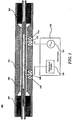
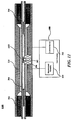
- FIG. 1 is a device for measuring a density of a fluid.
- device 100 includes a rigid housing 102, two bulkheads 104, a single flow tube 106, a first magnet 108 and a first coil 110 wound around first magnet 108, a second magnet 112 and a second coil 114 wound around second magnet 112, and test circuitry 116 which includes measurement circuitry 118 and current source 120.
- the rigid housing 102 surrounds and protects a volume through which flow tube 106 passes and reduces the response to vibrations not associated with particular vibratory modes of flow tube 106.
- Bulkheads 104 seal the volume and secure flow tube 106 within that volume.
- the volume preferably contains air, a vacuum or a relatively inert gas such as nitrogen or argon. If gasses are used, then they are preferably at atmospheric pressure when the device is at room temperature.
- Rigid housing 102, bulkheads 104, and flow tube 106 are preferably made from material in a configuration that can withstand pressures of more than 20,000 psi (pounds per square inch) at temperatures of 250 °C. or more.
- Two examples of suitable materials are Titanium and Hastaloy-HA276C.
- bulkheads 104 and flow tube 106 are constructed from the same piece of material, with bulkheads 104 being regions of larger diameter on either end of flow tube 106.
- flow tube 106 may be welded to bulkheads 104, or otherwise attached.
- rigid housing 102, bulkheads 104, and flow tube 106 are constructed from the same material in order to alleviate thermally induced stresses when the system is in thermal equilibrium.
- Device 100 may be a two magnet vibrating densitometer such as described in U.S. Patent No. 6,688,176 to Pelletier et al. , and assigned to the assignee of the present disclosure.
- Flow tube 106 is preferably straight, as this reduces any tendencies for plugging and erosion by materials passing through flow tube 106.
- bent tubes of various shapes including "U"-shaped tubes, may provide greater measurement sensitivities.
- first magnet 108 having first coil 110 wound thereon and second magnet 112 having second coil 114 wound thereon.
- First magnet 108 and first coil 110 correspond to a vibration detector of device 100 and second magnet 112 and second coil 114 correspond to a vibration source of device 100.
- the vibration source and vibration detector may be located side by side as shown in FIG. 1 the vibration source and vibration detector may be located on opposite sides of flow tube 106 at a point half way between the bulkheads 104 or in other configurations.
- second coil 114 is coupled to current source 120, which may be an alternating current source.
- current source 120 which may be an alternating current source.
- Application of an alternating current from current source 120 to second coil 114 generates an electromagnetic force that interacts with second magnet 112 and causes flow tube 106 to vibrate.
- First coil 110 is coupled to measurement circuitry 118, wherein the vibration in flow tube 106 moves first magnet 112 within first coil 110, therefore creating a voltage that is provided to measurement circuitry 118. From the provided voltages, measurement circuitry 118 calculates a fluid density of the fluid in flow tube 106.
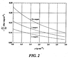
- FIG. 2 is a graph illustrating a sensitivity of a device for measuring a density of a fluid having two magnets attached to the flow tube, one magnet attached to the flow tube, and no magnets attached to the flow tube.
- the removal of one of the magnets from device 100 improves the sensitivity of device 100 by about 25%.
- the removal of both magnets improves the sensitivity of device 100 by about 80%.
- the removal of one of the magnets from device 100 allows for a magnet-coil combination to be placed at the exact center of flow tube 106.
- the expression for determining the frequency, and from the frequency the density, for device 100 has more than one thousand terms of transcendental functions. Removing one magnet and moving the remaining magnet-coil combination to the center provides a new expression which is less than twenty terms long. Consequently, using a single magnet-coil arrangement may provide not only greater sensitivity for determining a density of a fluid, but also be more useful in environments where computing power is limited, such as downhole environments.
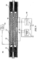
- FIG. 3 is a device for measuring a density of a fluid according to some embodiments.
- device 300 includes only a single magnet 302 coupled to flow tube 304.
- single magnet 302 may be mounted on flow tube 304, and in other embodiments, single magnet 302 may be spaced a predetermined distance away from flow tube 304.
- At least one coil 306 is wound around single magnet 302.
- at least one coil 306 comprises a single coil, however, consistent with other embodiments, at least one coil 306 may include a plurality of coils such as two coils wound around single magnet 302 in a differential arrangement.
- At least one coil 306 is coupled to test circuitry 308, which includes measurement circuitry 310 and current source 312. Consistent with some embodiments, current source 312 provides a current pulse to at least one coil 306. In other embodiments, current source 312 may be a direct current or alternating current source and provide a direct or alternating steady-state current to at least one coil 306.
- Device 300 also includes a rigid housing 314 and two bulkheads 316, similar to device 100 shown in FIG. 1 .
- Rigid housing 314 surrounds and protects a volume through which flow tube 304 passes and reduces the response to vibrations not associated with particular vibratory modes of flow tube 304.
- Bulkheads 316 seal the volume and secure flow tube 304 within that volume.
- the volume preferably contains air, a vacuum or a relatively inert gas such as nitrogen or argon. If gasses are used, then they are preferably at atmospheric pressure when the device is at room temperature.
- Rigid housing 314, bulkheads 316, and flow tube 304 are preferably made from material in a configuration that can withstand pressures of more than 20,000 psi (pounds per square inch) at temperatures of 250 °C. or more.
- Two examples of suitable materials are Titanium and Hastaloy-HA276C.
- bulkheads 316 and flow tube 304 are constructed from the same piece of material, with bulkheads 316 being regions of larger diameter on either end of flow tube 304.
- flow tube 304 may be welded to bulkheads 316, or otherwise attached.
- rigid housing 314, bulkheads 316, and flow tube 304 are constructed from the same material in order to alleviate thermally induced stresses when the system is in thermal equilibrium.
- single magnet 302 and at least one coil 306 act as both a vibration source and a vibration detector.
- Application of a current pulse from current source 312 to at least one coil 306 generates an electromagnetic force that interacts with single magnet 302 and causes flow tube 304 to vibrate.
- the vibration in flow tube 304 moves single magnet 302 within at least one coil 306, therefore creating a voltage on at least one coil 306.
- At least one coil 306 detects this voltage as it varies over time and provides the detected voltages to measurement circuitry 310. From the provided voltages, measurement circuitry 310 calculates a fluid density of the fluid in flow tube 304.
- measurement circuitry 310 performs an operation on the provided voltages and determines a resonance frequency of flow tube 304 from the resonance frequency.
- the operations may include a transform which transforms a time-based voltage function representing the voltage induced in at least one coil 306 over time to a frequency based function.
- the transform may be any known transform such as a discrete Fourier transform (DFT), a fast Fourier transform (FFT), or a discrete wavelet transform.
- DFT discrete Fourier transform
- FFT fast Fourier transform
- the fluid density of the fluid flowing in flow tube 304 can then be calculated from the determined resonance frequency.
- measurement circuitry 310 may include a spectral analyzer configured to perform a specific transform on the time-based voltage function.
- measurement circuitry 310 may include a processor configured to execute instructions stored in a memory coupled to the processor to perform a specific transform on the time-based voltage function and then execute further instructions stored in the memory to calculate a fluid density from a resonance frequency determined from the specific transform.
- measurement circuitry 310 may include application specific circuitry configured to perform a specific transform, determine a resonance frequency, and then determine a fluid density from the determined resonance frequency.
- measurement circuitry 310 may also include components capable of calculating further properties of the fluid, such as viscosity of the fluid.
- m T + m L ⁇ 2 ⁇ ⁇ t 2 ⁇ EI ⁇ 2 ⁇ ⁇ x 2 + f P + f T + f C + f V + f M
- t time
- ⁇ a transverse displacement of an element on flow tube 304
- x a distance of the element from one end of flow tube 304
- E an elastic modulus of flow tube
- I an area moment of inertia of flow tube 304
- m L is a linear density of the fluid inside flow tube 304
- m T is a linear density of material used to form flow tube 304
- f P is force on flow tube 304 due to pressure
- f T is additional tensile forces on flow tube 304
- f c is the Coriolis force
- f V is a force on flow tube 304 due to fluid flow
- f M is an additional mass loading due to the presence of magnet 302.
- T is a tension in flow tube 304
- V is a flow velocity of the fluid in flow tube 104
- M is the mass of magnet 302
- x 1 is a location of magnet 302 on flow tube 304
- ⁇ (x-x 1 ) is a Dirac delta-functions at x 1 .
- This equation may then by inverted to obtain a relationship of the density of the fluid in flow tube 304 as a function of the resonance frequency f 0 of the flow tube 304.
- measurement circuitry 310 may apply the above equations to determine a resonance frequency, and then determine a fluid density from the determined resonance frequency.
- single magnet 302 and at least one coil 304 are positioned along flow tube 304 such that single magnet 302 is mounted on flow tube 304 at a center position along the length of flow tube 304.
- single magnet 302 may be mounted on or arranged to be coupled to flow tube 304 at other points along the length of flow tube 304.
- the vibration sources and detectors are preferably positioned so as to be near antinodes for each of the vibration modes of interest.
- the locations of nodes (points of zero vibrational amplitude) and antinodes are determined by the wavelength of the vibration mode and by the mounting of flow tube 304.
- FIG. 4 is a graph illustrating a waveform of a voltage detected as the flow tube vibrates over time.
- a magnetic field produced by single magnet 302 fluctuates as it moves within at least one coil 306.
- the fluctuating magnetic field produces a voltage in at least one coil 306 which, as shown in FIG. 4 , decays over time. This voltage is then provided to measurement circuitry 310 to determine, among other parameters, a resonant frequency of flow tube 304.
- the voltage decays over time.
- the rate of decay can be determined by measurement circuitry 310 to further determine a Q-factor of the at least one coil 306 vibration detector.
- the Q-factor of the single coil 306 vibration detector is directly related to the viscosity of the fluid in flow tube 304. Consequently, by determining a Q-factor for the vibration detector, the viscosity of the fluid flowing in flow tube 304.
- FIG. 5 is a graph shown a calculated signal power spectral density from the detected voltage shown in FIG. 4 .
- the signal power spectral density is calculated using a transform which transforms the time-based voltage function shown in FIG. 4 to a frequency based function, such as shown in FIG. 5 .
- the transform may be any known transform such as a discrete Fourier transform (DFT), a fast Fourier transform (FFT), or a discrete wavelet transform.
- DFT discrete Fourier transform
- FFT fast Fourier transform
- a transform of the time-based voltage function produces a graph of frequency versus signal strength wherein the resonant frequency of flow tube 304 will correspond to the strongest peak of the function.
- the resonant frequency is shown in FIG. 5 as being approximately 1165 Hz.
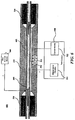
- FIG. 6 is a device for measuring a density of a fluid according to some embodiments.
- Device 600 shown in FIG. 6 is similar to device 300 shown in FIG. 3 , so elements which remain the same will not be discussed in detail.
- device 600 differs from device 300 in that metallic wire 602 is used as a vibration detector.
- metallic wire 602 may be a fine metallic wire made of platinum or copper.
- a known current I is applied to metallic wire 602 from wire current source 604 that produces a voltage V in metallic wire 602 based on a resistance R of metallic wire.
- measurement circuitry 310 can further analyze the temporal decay rate of the voltage to determine a Q-factor of the metallic wire 602 vibration detector. Then, the determined Q-factor can be used to determine viscosity of the fluid flowing in flow tube 304.
- FIG. 7 is a device for measuring a density of a fluid according to some embodiments.
- Device 700 shown in FIG. 7 is similar to device 600 shown in FIG. 6 , so elements that remain the same will not be discussed in detail.
- device 700 differs from device 600 in that strain gauge 702 is used as a vibration detector.
- strain gauge 702 may be an insulator material 704 deposited along a length of flow tube 304 and a metallic or semiconducting material 706 deposited over insulator material 704. Insulator material 704 and metallic or semiconducting material 706 may be deposited on flow tube 304 using known deposition methods.
- a known current I is applied to strain gauge 702 from strain gauge current source 708 that produces a voltage V in metallic or semiconductor material 706 based on a resistance R of metallic or semiconductor material 706.
- strain gauge current source 708 that produces a voltage V in metallic or semiconductor material 706 based on a resistance R of metallic or semiconductor material 706.
- the voltage variations are detected by measurement circuitry 310 and used to calculate a resonance frequency in the same way as discussed above with respect to FIGS. 3-5 .
- measurement circuitry 310 can further analyze the temporal decay rate of the voltage to determine a Q-factor of the strain gauge 702 vibration detector. Then, the determined Q-factor can be used to determine viscosity of the fluid flowing in flow tube 304.
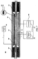
- FIG. 8 is a device for measuring a density of a fluid according to some embodiments.
- Device 800 shown in FIG. 8 is similar to device 600 shown in FIG. 6 , so elements which remain the same will not be discussed in detail.
- device 800 differs from device 600 in that fiber optic sensor 802 is used as a vibration detector.
- fiber optic sensor 802 may be a fiber Bragg grating, which includes the fiber optic core 804 surrounded by the fiber optic cladding material 806 with a Bragg grating 808 enclosed in a portion of fiber optic core 804.
- Bragg grating 808 acts as a period or aperiodic perturbation of the effective refractive index in fiber optic core 804.
- the wavelength ⁇ of maximum reflectivity (or Bragg wavelength) depends on the grating period ⁇ as well as temperature and mechanical strain, as both of these factors influence the effective refractive index ⁇ eff of Bragg grating 808 and thus produce changes in the light that is transmitted through or reflected back in fiber optic sensor 802.
- measurement circuitry 310 may include an optical sensor that is able to detect these changes and use the changes of light to determine the mechanical stress of flow tube 304 from the vibration of flow tube 304 to determine a resonance frequency of flow tube 304 in a manner similar to that discussed above with respect to FIGS. 3-5 .
- the density of the fluid flowing through flow tube 304 may then be determined from the determined resonance frequency.
- measurement circuitry 310 can further analyze the temporal decay rate of the voltage to determine a Q-factor of the fiber optic sensor 802. Then, the determined Q-factor can be used to determine viscosity of the fluid flowing in flow tube 304.
- FIG. 9 is a device for measuring a density of a fluid according to some embodiments.
- Device 900 shown in FIG. 9 is similar to device 600 shown in FIG. 6 , so elements that remain the same will not be discussed in detail.
- device 900 differs from device 600 in that strain gauge metallic wire 602 is wrapped around flow tube 304.
- metallic wire 602 may be a fine metallic wire made of platinum or copper.
- strain gauge 702 or fiber optic sensor 802 may be substituted for metallic wire 602 and be wrapped around flow tube 304.
- a known current I is applied to metallic wire 602 from wire current source 604, which produces a voltage V in metallic wire 602 based on a resistance R of metallic wire.
- measurement circuitry 310 can further analyze the temporal decay rate of the voltage to determine a Q-factor of the metallic wire 602 vibration detector. Then, the determined Q-factor can be used to determine viscosity of the fluid flowing in flow tube 304.
- the hoop stress of flow tube 304 may be determined.
- the change in radius ⁇ results in a change in the outer circumference ( 2 ⁇ ) of the tube which in turn results in minute change in the resistance R of metallic wire 602 wrapped around flow tube 304.
- FIG. 10 is a device for measuring a density of a fluid according to some embodiments.
- Device 1000 shown in FIG. 10 is similar to device 300 shown in FIG. 3 , so elements that remain the same will not be discussed in detail. However, device 1000 differs from device 300 in that electric hammer 1002 is used as a vibration source.
- single magnet 302 is spaced away from flow tube 304 by a predetermined amount such that single magnet 302 is not mounted on flow tube 304. Referring back to FIG. 2 , removing single magnet 302 from flow tube 304 such that no magnets are mounted on flow tube 304 may provide a sensitivity increase of almost 80% when compared with the two magnet embodiment shown in FIG. 1 .
- current source 312 is coupled to electric hammer 1002 and is capable of providing a current pulse to electric hammer 1002 causing electric hammer 1002 to strike flow tube 304 such that flow tube 304 vibrates.
- the vibration in flow tube 304 moves single magnet 302 within at least one coil 306, therefore creating a voltage.
- At least one coil 306 detects this voltage as it varies over time and provides the detected voltages to measurement circuitry 310. From the provided voltages, measurement circuitry 310 calculates a fluid density of the fluid in flow tube 304, as described above with respect to FIGS. 4 and 5 . Further, as discussed above with respect to FIG.
- measurement circuitry 310 can further analyze the temporal decay rate of the voltage to determine a Q-factor of the single coil vibration detector. Because the viscosity of a fluid influences the Q-factor of a vibratory device, the determined Q-factor can be used to determine viscosity of the fluid flowing in flow tube 304.
- FIG. 11 is a device for measuring a density of a fluid according to some embodiments.
- Device 1100 shown in FIG. 11 is similar to device 300 shown in FIG. 3 , so elements which remain the same will not be discussed in detail. However, device 1100 differs from device 300 in that single magnet 302 is attached to a tab 1102 mounted on a side of flow tube 304.
- current source 312 provides a pulse current to at least one coil 306
- the electromagnetic field produced by at least one coil 306 interacts with single magnet 302 to cause single magnet 302 to apply a normal force on tab 1102, which applies a torque on flow tube 304, and creates a torsional vibration in flow tube 304.
- electric hammer 1002 may be used as a vibration source instead of single magnet 302 such that electric hammer 1002 strikes tab 1102 to create a torsional vibration in flow tube 304.
- the torsional vibration will cause single magnet 302 to move within at least one coil 306 and create a voltage on at least one coil 306 that is provided to measurement circuitry 312 and can be used to determine a resonance frequency and, thus, a density of the fluid flowing in flow tube 304.
- the viscosity of the fluid flowing in flow tube 304 can also be determined. This may be done by determining the Q-factor of the torsional vibration which is directly influenced by viscosity, as discussed above.
- device 1100 allows for the simultaneous determination of both the density and viscosity of the fluid flowing in flow tube.
- embodiments described herein provide improvements in the design of fluid densitometers.
- embodiments described herein use a single magnet and at least onecoil mounted on a flow tube, which provides greater sensitivity and over two magnet embodiments.
- Single magnet and at least one coil embodiments also provide for greater ease in calculating the fluid density based on a monitored vibration of the flow tube.
- single magnet and at least one coil embodiments only require a single magnet to be mounted on the flow tube, providing for ease of construction.
- Other embodiments disclosed herein may provide greater sensitivity by removing the magnet entirely from the flow tube and instead driving a vibration using an electric hammer.
- embodiments use strain gauges, resistant detectors, and optical detection device which allow other properties, such as a fluid viscosity or fluid pressure to be measured along with the fluid density.
- embodiments as described herein provide a device for measuring a torsional vibration which can be used to determine the fluid viscosity along with the fluid density.
- Embodiments described herein are exemplary only. One skilled in the art may recognize various alternative embodiments from those specifically disclosed. Those alternative embodiments are also intended to be within the scope of this disclosure. As such, the embodiments are limited only by the claims below.
Landscapes
- Life Sciences & Earth Sciences (AREA)
- Engineering & Computer Science (AREA)
- Physics & Mathematics (AREA)
- Geology (AREA)
- Mining & Mineral Resources (AREA)
- Chemical & Material Sciences (AREA)
- Health & Medical Sciences (AREA)
- Immunology (AREA)
- General Physics & Mathematics (AREA)
- Pathology (AREA)
- Analytical Chemistry (AREA)
- Biochemistry (AREA)
- General Health & Medical Sciences (AREA)
- Environmental & Geological Engineering (AREA)
- General Life Sciences & Earth Sciences (AREA)
- Geochemistry & Mineralogy (AREA)
- Fluid Mechanics (AREA)
- Geophysics (AREA)
- Chemical Kinetics & Catalysis (AREA)
- Medicinal Chemistry (AREA)
- Food Science & Technology (AREA)
- General Chemical & Material Sciences (AREA)
- Oil, Petroleum & Natural Gas (AREA)
- Electrochemistry (AREA)
- Measuring Volume Flow (AREA)
- Measuring Fluid Pressure (AREA)
- Investigating Or Analyzing Materials By The Use Of Magnetic Means (AREA)
Abstract
Description
- Embodiments disclosed herein generally relate to the measurement of fluid properties. In particular, the disclosed embodiments are related to determining a density of a fluid using a single magnet fluid densitometer.
- There are many instances in industrial processes and controls for handling flowing fluids where the density of the moving fluid has to be determined accurately. One particular application is in the identification of reservoir fluids flowing in a well such as in a pumpout wireline formation tester (PWFT) or logging while drilling formation tester (LWDFT) used to collect reservoir fluid samples in a well drilled for hydrocarbon exploration. The in-situ determination of fluid density under reservoir conditions is of vital importance in formation evaluation. Water often co-exists with gaseous hydrocarbons and crude oil in some common geologic formations. As such, a mixture of water, gaseous hydrocarbons, and liquid hydrocarbons is often produced by a working oil well, and the mixture is ultimately separated at a downstream location. It is often desirable to determine the amount of oil that is produced in a stream flowing from a formation. Because the amount of oil produced in the stream will influence the density of the fluid, measuring the density of the fluid can provide a reasonable estimation as to the amount of oil in the fluid.
- One example of a densitometer that can be used to measure the density of an unknown process fluid is a Coriolis mass flowmeter, such as disclosed in
U.S. Pat. No. 4,491,025, issued to Smith et al. . A Coriolis mass flowmeter may contain two parallel conduits, each typically being a U-shaped flow tube wherein each flow tube is driven such that it oscillates about an axis causing each tube to twist about a torsional axis to produce a slight deformation and deflection of the conduit proportional to the mass flow rate of the fluid. This deformation is normally measured as a small difference between the deflection at the inlet ends of the conduits compared to the deflection at the outlet ends. Both tubes are oppositely driven such that each tube behaves as a separate tine of a tuning fork and thereby cancels any undesirable vibrations that might otherwise mask the Coriolis forces. The resonant frequency at which each flow tube oscillates depends upon its total mass, i.e. the mass of the empty tube itself plus the mass of the fluid flowing therethrough. Inasmuch as the total mass will vary as the density of the fluid flowing through the tube varies, the resonant frequency will likewise vary with any changes in density. - Another example of a densitometer is discussed in
U.S. Pat. No. 4,491,009, issued to Reusch , wherein the density of an unknown fluid flowing through an oscillating flow tube is proportional to the square of the period at which the tube resonates. A further exemplary densitometer is disclosed inU.S. Pat. No. 6,378,364, by Pelletier et al. , which is assigned to the same assignee as the present disclosure. Therein, a measurement device compares vibration frequencies from a sample cavity and a reference cavity to determine desired fluid properties. - However, due to the limited space in downhole applications, in most of the densitometers described above, the transmitter or driver is often located in close proximity to the receiver and may cause interference between the two components. The interference may distort the signal picked up on the receiver and cause difficulty in accurately recognizing the vibratory response of the flow tube. Thus, many of the prior art methods have used multiple flow tubes to create a reference point to cancel out external interference.
- Consequently, there is a need for a high-accuracy densitometer which is capable of operation under the high temperature, pressure, shock and vibration conditions encountered in a wellbore. There is also a need for a densitometer which allows for a greater ease of construction and improved sensitivity over existing densitometers. Furthermore, there is a need for a device that not only is capable of determining a density of a fluid, but can also simultaneously determine other properties of a fluid, such as a fluid pressure and a fluid viscosity.
- Consistent with some embodiments, an instrument for measuring fluid properties is provided. The instrument includes a tube that receives a sample of the fluid, a single magnet coupled to the tube, at least one coil wound around the single magnet, and a testing module coupled to the at least one coil wound around the single magnet.
- Consistent with further embodiments, there is also provided an instrument for determining fluid properties. The instrument includes a tube receiving the fluid, a single magnet attached to the tube, and at least one coil wound around the single magnet. The at least one coil is coupled to a pulse current source and receives a pulse current that creates a magnetic field in the at least one coil, the created magnetic field interacting with the single magnet to drive the tube to vibrate. The instrument further includes a detector coupled to the tube, wherein the detector is coupled to measurement circuitry and detects properties of the tube as it vibrates, and the measurement circuitry determines the fluid properties based on the detected properties.
- These and other embodiments will be described in further detail below, with reference to the following drawings.
-
-
FIG. 1 is a device for measuring a density of a fluid. -
FIG. 2 is a graph illustrating a sensitivity of a device for measuring a density of a fluid having two magnets attached to the flow tube, one magnet attached to the flow tube, and no magnets attached to the flow tube. -
FIG. 3 is a device for measuring a density of a fluid according to some embodiments. -
FIG. 4 is a graph illustrating a waveform of a voltage detected as the flow tube vibrates over time. -
FIG. 5 is a graph showing a calculated signal power spectral density from the detected voltage shown inFIG. 4 . -
FIG. 6 is a device for measuring a density of a fluid according to some embodiments. -
FIG. 7 is a device for measuring a density of a fluid according to some embodiments. -
FIG. 8 is a device for measuring a density of a fluid according to some embodiments. -
FIG. 9 is a device for measuring a density of a fluid according to some embodiments. -
FIG. 10 is a device for measuring a density of a fluid according to some embodiments. -
FIG. 11 is a device for measuring a density of a fluid according to some embodiments. - Wherever possible, the same reference numbers are used throughout the drawings to refer to the same or like elements.
-
FIG. 1 is a device for measuring a density of a fluid. As shown inFIG. 1 ,device 100 includes arigid housing 102, twobulkheads 104, asingle flow tube 106, afirst magnet 108 and afirst coil 110 wound aroundfirst magnet 108, asecond magnet 112 and asecond coil 114 wound aroundsecond magnet 112, andtest circuitry 116 which includesmeasurement circuitry 118 andcurrent source 120. Therigid housing 102 surrounds and protects a volume through whichflow tube 106 passes and reduces the response to vibrations not associated with particular vibratory modes offlow tube 106. Bulkheads 104 seal the volume andsecure flow tube 106 within that volume. The volume preferably contains air, a vacuum or a relatively inert gas such as nitrogen or argon. If gasses are used, then they are preferably at atmospheric pressure when the device is at room temperature. -
Rigid housing 102,bulkheads 104, andflow tube 106 are preferably made from material in a configuration that can withstand pressures of more than 20,000 psi (pounds per square inch) at temperatures of 250 °C. or more. Two examples of suitable materials are Titanium and Hastaloy-HA276C. Preferably,bulkheads 104 andflow tube 106 are constructed from the same piece of material, withbulkheads 104 being regions of larger diameter on either end offlow tube 106. Alternatively,flow tube 106 may be welded tobulkheads 104, or otherwise attached. Preferably,rigid housing 102,bulkheads 104, andflow tube 106 are constructed from the same material in order to alleviate thermally induced stresses when the system is in thermal equilibrium.Device 100 may be a two magnet vibrating densitometer such as described inU.S. Patent No. 6,688,176 to Pelletier et al. , and assigned to the assignee of the present disclosure. -
Flow tube 106 is preferably straight, as this reduces any tendencies for plugging and erosion by materials passing throughflow tube 106. However, it is recognized that bent tubes of various shapes, including "U"-shaped tubes, may provide greater measurement sensitivities. - As described above, attached to flow
tube 106 arefirst magnet 108 havingfirst coil 110 wound thereon andsecond magnet 112 havingsecond coil 114 wound thereon.First magnet 108 andfirst coil 110 correspond to a vibration detector ofdevice 100 andsecond magnet 112 andsecond coil 114 correspond to a vibration source ofdevice 100. Although the vibration source and vibration detector may be located side by side as shown inFIG. 1 the vibration source and vibration detector may be located on opposite sides offlow tube 106 at a point half way between thebulkheads 104 or in other configurations. - As shown in
FIG. 1 ,second coil 114 is coupled tocurrent source 120, which may be an alternating current source. Application of an alternating current fromcurrent source 120 tosecond coil 114 generates an electromagnetic force that interacts withsecond magnet 112 and causes flowtube 106 to vibrate.First coil 110 is coupled tomeasurement circuitry 118, wherein the vibration inflow tube 106 movesfirst magnet 112 withinfirst coil 110, therefore creating a voltage that is provided tomeasurement circuitry 118. From the provided voltages,measurement circuitry 118 calculates a fluid density of the fluid inflow tube 106. - However, the use of two magnet-coil arrangements as shown in
FIG. 1 has decreased sensitivity due to the two magnets being attached to the flow tube.FIG. 2 is a graph illustrating a sensitivity of a device for measuring a density of a fluid having two magnets attached to the flow tube, one magnet attached to the flow tube, and no magnets attached to the flow tube. As shown inFIG. 2 , the removal of one of the magnets fromdevice 100 improves the sensitivity ofdevice 100 by about 25%. Moreover, the removal of both magnets improves the sensitivity ofdevice 100 by about 80%. Further, the removal of one of the magnets fromdevice 100 allows for a magnet-coil combination to be placed at the exact center offlow tube 106. Placing the magnet-coil combination at the center offlow tube 106 drastically reduces the complexity of the calculations and modeling needed to analyze the provided voltages and determine a fluid density. Indeed, the expression for determining the frequency, and from the frequency the density, fordevice 100 has more than one thousand terms of transcendental functions. Removing one magnet and moving the remaining magnet-coil combination to the center provides a new expression which is less than twenty terms long. Consequently, using a single magnet-coil arrangement may provide not only greater sensitivity for determining a density of a fluid, but also be more useful in environments where computing power is limited, such as downhole environments. -
FIG. 3 is a device for measuring a density of a fluid according to some embodiments. As shown inFIG. 3 ,device 300 includes only asingle magnet 302 coupled to flowtube 304. Consistent with some embodiments,single magnet 302 may be mounted onflow tube 304, and in other embodiments,single magnet 302 may be spaced a predetermined distance away fromflow tube 304. At least onecoil 306 is wound aroundsingle magnet 302. As shown inFIG. 3 , at least onecoil 306 comprises a single coil, however, consistent with other embodiments, at least onecoil 306 may include a plurality of coils such as two coils wound aroundsingle magnet 302 in a differential arrangement. At least onecoil 306 is coupled to testcircuitry 308, which includesmeasurement circuitry 310 andcurrent source 312. Consistent with some embodiments,current source 312 provides a current pulse to at least onecoil 306. In other embodiments,current source 312 may be a direct current or alternating current source and provide a direct or alternating steady-state current to at least onecoil 306. -
Device 300 also includes arigid housing 314 and twobulkheads 316, similar todevice 100 shown inFIG. 1 .Rigid housing 314 surrounds and protects a volume through which flowtube 304 passes and reduces the response to vibrations not associated with particular vibratory modes offlow tube 304.Bulkheads 316 seal the volume andsecure flow tube 304 within that volume. The volume preferably contains air, a vacuum or a relatively inert gas such as nitrogen or argon. If gasses are used, then they are preferably at atmospheric pressure when the device is at room temperature.Rigid housing 314,bulkheads 316, and flowtube 304 are preferably made from material in a configuration that can withstand pressures of more than 20,000 psi (pounds per square inch) at temperatures of 250 °C. or more. Two examples of suitable materials are Titanium and Hastaloy-HA276C. Preferably,bulkheads 316 and flowtube 304 are constructed from the same piece of material, withbulkheads 316 being regions of larger diameter on either end offlow tube 304. Alternatively, flowtube 304 may be welded tobulkheads 316, or otherwise attached. Preferably,rigid housing 314,bulkheads 316, and flowtube 304 are constructed from the same material in order to alleviate thermally induced stresses when the system is in thermal equilibrium. - Consistent with some embodiments,
single magnet 302 and at least onecoil 306 act as both a vibration source and a vibration detector. Application of a current pulse fromcurrent source 312 to at least onecoil 306 generates an electromagnetic force that interacts withsingle magnet 302 and causes flowtube 304 to vibrate. After the current pulse has been applied, the vibration inflow tube 304 movessingle magnet 302 within at least onecoil 306, therefore creating a voltage on at least onecoil 306. At least onecoil 306 detects this voltage as it varies over time and provides the detected voltages tomeasurement circuitry 310. From the provided voltages,measurement circuitry 310 calculates a fluid density of the fluid inflow tube 304. In someembodiments measurement circuitry 310 performs an operation on the provided voltages and determines a resonance frequency offlow tube 304 from the resonance frequency. Consistent with some embodiments, the operations may include a transform which transforms a time-based voltage function representing the voltage induced in at least onecoil 306 over time to a frequency based function. The transform may be any known transform such as a discrete Fourier transform (DFT), a fast Fourier transform (FFT), or a discrete wavelet transform. The fluid density of the fluid flowing inflow tube 304 can then be calculated from the determined resonance frequency. - Further consistent with some embodiments,
measurement circuitry 310 may include a spectral analyzer configured to perform a specific transform on the time-based voltage function. Alternatively,measurement circuitry 310 may include a processor configured to execute instructions stored in a memory coupled to the processor to perform a specific transform on the time-based voltage function and then execute further instructions stored in the memory to calculate a fluid density from a resonance frequency determined from the specific transform. As yet another alternative,measurement circuitry 310 may include application specific circuitry configured to perform a specific transform, determine a resonance frequency, and then determine a fluid density from the determined resonance frequency. Furthermore,measurement circuitry 310 may also include components capable of calculating further properties of the fluid, such as viscosity of the fluid. - For example, the motion of
flow tube 304 as it vibrates may be described by the following equation:
flow tube 304, x is a distance of the element from one end offlow tube 304, E is an elastic modulus of flow tube, I is an area moment of inertia offlow tube 304, mL is a linear density of the fluid insideflow tube 304, mT is a linear density of material used to formflow tube 304, fP is force onflow tube 304 due to pressure, fT is additional tensile forces onflow tube 304,fc is the Coriolis force, fV is a force onflow tube 304 due to fluid flow, and fM is an additional mass loading due to the presence ofmagnet 302. From detailed force analysis, it can be shown that the forces are given by:


flow tube 304, V is a flow velocity of the fluid inflow tube 104, M is the mass ofmagnet 302, x1 is a location ofmagnet 302 onflow tube 304, and δ(x-x1) is a Dirac delta-functions at x1. When temperature, pressure, and fluid density are known, the differential equation can be solved to yield the wave number β 0 that is related to the resonance frequency f 0 of theflow tube 104 as a function of fluid density:
flow tube 304 as a function of the resonance frequency f 0 of theflow tube 304. Consistent with some embodiments,measurement circuitry 310 may apply the above equations to determine a resonance frequency, and then determine a fluid density from the determined resonance frequency. - As shown in
FIG. 3 ,single magnet 302 and at least onecoil 304 are positioned alongflow tube 304 such thatsingle magnet 302 is mounted onflow tube 304 at a center position along the length offlow tube 304. However, in some embodiments,single magnet 302 may be mounted on or arranged to be coupled to flowtube 304 at other points along the length offlow tube 304. In such embodiments, it is preferable thatsingle magnet 302 and at least onecoil 306 be mounted near an antinode (point of maximum displacement from the equilibrium position) of the mode of vibration they are intended to excite and monitor. It is contemplated that more than one mode of vibration may be employed (e.g. the vibration source may switch between multiple frequencies to obtain information from higher resonance harmonic frequencies). The vibration sources and detectors are preferably positioned so as to be near antinodes for each of the vibration modes of interest. The locations of nodes (points of zero vibrational amplitude) and antinodes are determined by the wavelength of the vibration mode and by the mounting offlow tube 304. The frequency f and wavelength λ are related to the speed of sound v in the material by the equation v=f λ. -
FIG. 4 is a graph illustrating a waveform of a voltage detected as the flow tube vibrates over time. As shown inFIG. 4 , at t=0, at least onecoil 306 is modeled as a single coil, and is excited with a current pulse which produces an electromagnetic field to be produced by at least onecoil 306 that causesflow tube 304 to vibrate. Asflow tube 304 vibrates, a magnetic field produced bysingle magnet 302 fluctuates as it moves within at least onecoil 306. The fluctuating magnetic field produces a voltage in at least onecoil 306 which, as shown inFIG. 4 , decays over time. This voltage is then provided tomeasurement circuitry 310 to determine, among other parameters, a resonant frequency offlow tube 304. - Moreover, as shown in
FIG. 4 , the voltage decays over time. The rate of decay can be determined bymeasurement circuitry 310 to further determine a Q-factor of the at least onecoil 306 vibration detector. The Q-factor of thesingle coil 306 vibration detector is directly related to the viscosity of the fluid inflow tube 304. Consequently, by determining a Q-factor for the vibration detector, the viscosity of the fluid flowing inflow tube 304. -
FIG. 5 is a graph shown a calculated signal power spectral density from the detected voltage shown inFIG. 4 . Consistent with some embodiments, the signal power spectral density is calculated using a transform which transforms the time-based voltage function shown inFIG. 4 to a frequency based function, such as shown inFIG. 5 . The transform may be any known transform such as a discrete Fourier transform (DFT), a fast Fourier transform (FFT), or a discrete wavelet transform. As shown inFIG. 5 , a transform of the time-based voltage function produces a graph of frequency versus signal strength wherein the resonant frequency offlow tube 304 will correspond to the strongest peak of the function. For example, for the voltage waveform shown inFIG. 4 , the resonant frequency is shown inFIG. 5 as being approximately 1165 Hz. -
FIG. 6 is a device for measuring a density of a fluid according to some embodiments.Device 600 shown inFIG. 6 is similar todevice 300 shown inFIG. 3 , so elements which remain the same will not be discussed in detail. However,device 600 differs fromdevice 300 in thatmetallic wire 602 is used as a vibration detector. Consistent with some embodiments,metallic wire 602 may be a fine metallic wire made of platinum or copper. In operation, a known current I is applied tometallic wire 602 from wirecurrent source 604 that produces a voltage V inmetallic wire 602 based on a resistance R of metallic wire. Asflow tube 304 vibrates, it also bends, which creates mechanical stress along the length offlow tube 304. This created mechanical stress produces variations in resistance R ofmetallic wire 602 which, according to Ohm's Law, will also create voltage variations inmetallic wire 602. The voltage variations are detected bymeasurement circuitry 310 and used to calculate a resonance frequency in the same way as discussed above with respect toFIGS. 3-5 . Further, as discussed above with respect toFIG. 4 ,measurement circuitry 310 can further analyze the temporal decay rate of the voltage to determine a Q-factor of themetallic wire 602 vibration detector. Then, the determined Q-factor can be used to determine viscosity of the fluid flowing inflow tube 304. -
FIG. 7 is a device for measuring a density of a fluid according to some embodiments.Device 700 shown inFIG. 7 is similar todevice 600 shown inFIG. 6 , so elements that remain the same will not be discussed in detail. However,device 700 differs fromdevice 600 in thatstrain gauge 702 is used as a vibration detector. Consistent with some embodiments,strain gauge 702 may be an insulator material 704 deposited along a length offlow tube 304 and a metallic orsemiconducting material 706 deposited over insulator material 704. Insulator material 704 and metallic orsemiconducting material 706 may be deposited onflow tube 304 using known deposition methods. In operation, a known current I is applied tostrain gauge 702 from strain gaugecurrent source 708 that produces a voltage V in metallic orsemiconductor material 706 based on a resistance R of metallic orsemiconductor material 706. Asflow tube 304 vibrates, it also bends which creates mechanical stress along the length offlow tube 304. This created mechanical stress produces variations in resistance R ofstrain gauge 702 that, according to Ohm's Law, will also create voltage variations in metallic orsemiconductor material 706. The voltage variations are detected bymeasurement circuitry 310 and used to calculate a resonance frequency in the same way as discussed above with respect toFIGS. 3-5 . Further, as discussed above with respect toFIG. 4 ,measurement circuitry 310 can further analyze the temporal decay rate of the voltage to determine a Q-factor of thestrain gauge 702 vibration detector. Then, the determined Q-factor can be used to determine viscosity of the fluid flowing inflow tube 304. -
FIG. 8 is a device for measuring a density of a fluid according to some embodiments.Device 800 shown inFIG. 8 is similar todevice 600 shown inFIG. 6 , so elements which remain the same will not be discussed in detail. However,device 800 differs fromdevice 600 in thatfiber optic sensor 802 is used as a vibration detector. Consistent with some embodiments,fiber optic sensor 802 may be a fiber Bragg grating, which includes thefiber optic core 804 surrounded by the fiberoptic cladding material 806 with a Bragg grating 808 enclosed in a portion offiber optic core 804. Bragg grating 808 acts as a period or aperiodic perturbation of the effective refractive index infiber optic core 804. The refractive index perturbation results in a reflection of light propagating throughfiber optic sensor 802 fromlight source 810 in a narrow range of wavelengths, for which a Bragg condition is satisfied:
fiber optic sensor 802. The wavelength λ of maximum reflectivity (or Bragg wavelength) depends on the grating period ∧ as well as temperature and mechanical strain, as both of these factors influence the effective refractive index ηeff of Bragg grating 808 and thus produce changes in the light that is transmitted through or reflected back infiber optic sensor 802. Asflow tube 304 vibrates, it also bends which creates mechanical stress along the length offlow tube 304. This created mechanical stress will influence the effective refractive index ηeff of Bragg grating 808 and thus produce changes in the light that is transmitted throughfiber optic sensor 802. Consequently,measurement circuitry 310 may include an optical sensor that is able to detect these changes and use the changes of light to determine the mechanical stress offlow tube 304 from the vibration offlow tube 304 to determine a resonance frequency offlow tube 304 in a manner similar to that discussed above with respect toFIGS. 3-5 . The density of the fluid flowing throughflow tube 304 may then be determined from the determined resonance frequency. Further, as discussed above with respect toFIG. 4 ,measurement circuitry 310 can further analyze the temporal decay rate of the voltage to determine a Q-factor of thefiber optic sensor 802. Then, the determined Q-factor can be used to determine viscosity of the fluid flowing inflow tube 304. -
FIG. 9 is a device for measuring a density of a fluid according to some embodiments. Device 900 shown inFIG. 9 is similar todevice 600 shown inFIG. 6 , so elements that remain the same will not be discussed in detail. However, device 900 differs fromdevice 600 in that strain gaugemetallic wire 602 is wrapped aroundflow tube 304. Consistent with some embodiments,metallic wire 602 may be a fine metallic wire made of platinum or copper. In other embodiments,strain gauge 702 orfiber optic sensor 802 may be substituted formetallic wire 602 and be wrapped aroundflow tube 304. In operation, a known current I is applied tometallic wire 602 from wirecurrent source 604, which produces a voltage V inmetallic wire 602 based on a resistance R of metallic wire. Asflow tube 304 vibrates, it also bends which creates mechanical stress along the length offlow tube 304. This created mechanical stress produces variations in resistance R ofmetallic wire 602 that, according to Ohm's Law, will also create voltage variations inmetallic wire 602. The voltage variations are detected bymeasurement circuitry 310 and used to calculate a resonance frequency in the same way as discussed above with respect toFIGS. 3-5 . Further, as discussed above with respect toFIG. 4 ,measurement circuitry 310 can further analyze the temporal decay rate of the voltage to determine a Q-factor of themetallic wire 602 vibration detector. Then, the determined Q-factor can be used to determine viscosity of the fluid flowing inflow tube 304. - Consistent with some embodiments, using metallic wire 602 (or
strain gauge 702 or optic sensor 802) wrapped aroundflow tube 304, the hoop stress offlow tube 304 may be determined. Under a pressure P, a flow tube such asflow tube 304, with inner radius b and outer radius α will experience expansion in its outer radius by
flow tube 304, and v is the Poisson's ratio offlow tube 304. The change in radius Δα results in a change in the outer circumference (2πα) of the tube which in turn results in minute change in the resistance R ofmetallic wire 602 wrapped aroundflow tube 304. This resistance change ΔR may then be measured using well known methods, such as using a quarter-bridge Wheatstone bridge composed ofmetallic wire 602 and three dummy resistors and excited by a voltage Vbr, such that the strain ε from pressure P may be determined by
metallic wire 602. Because the strain ε may be equal to
flow tube 304 can be determined using equation (10). Once the pressure P is determined,measurement circuitry 310 may then determine the hoop stress δθ offlow tube 304 using the equation
flow tube 304, and r is the radius offlow tube 304. -
FIG. 10 is a device for measuring a density of a fluid according to some embodiments.Device 1000 shown inFIG. 10 is similar todevice 300 shown inFIG. 3 , so elements that remain the same will not be discussed in detail. However,device 1000 differs fromdevice 300 in thatelectric hammer 1002 is used as a vibration source. As shown inFIG. 10 ,single magnet 302 is spaced away fromflow tube 304 by a predetermined amount such thatsingle magnet 302 is not mounted onflow tube 304. Referring back toFIG. 2 , removingsingle magnet 302 fromflow tube 304 such that no magnets are mounted onflow tube 304 may provide a sensitivity increase of almost 80% when compared with the two magnet embodiment shown inFIG. 1 . - In operation,
current source 312 is coupled toelectric hammer 1002 and is capable of providing a current pulse toelectric hammer 1002 causingelectric hammer 1002 to strikeflow tube 304 such thatflow tube 304 vibrates. After the current pulse has been applied, the vibration inflow tube 304 movessingle magnet 302 within at least onecoil 306, therefore creating a voltage. At least onecoil 306 detects this voltage as it varies over time and provides the detected voltages tomeasurement circuitry 310. From the provided voltages,measurement circuitry 310 calculates a fluid density of the fluid inflow tube 304, as described above with respect toFIGS. 4 and 5 . Further, as discussed above with respect toFIG. 4 ,measurement circuitry 310 can further analyze the temporal decay rate of the voltage to determine a Q-factor of the single coil vibration detector. Because the viscosity of a fluid influences the Q-factor of a vibratory device, the determined Q-factor can be used to determine viscosity of the fluid flowing inflow tube 304. -
FIG. 11 is a device for measuring a density of a fluid according to some embodiments.Device 1100 shown inFIG. 11 is similar todevice 300 shown inFIG. 3 , so elements which remain the same will not be discussed in detail. However,device 1100 differs fromdevice 300 in thatsingle magnet 302 is attached to atab 1102 mounted on a side offlow tube 304. Thus, whencurrent source 312 provides a pulse current to at least onecoil 306, the electromagnetic field produced by at least onecoil 306 interacts withsingle magnet 302 to causesingle magnet 302 to apply a normal force ontab 1102, which applies a torque onflow tube 304, and creates a torsional vibration inflow tube 304. According to some embodiments,electric hammer 1002 may be used as a vibration source instead ofsingle magnet 302 such thatelectric hammer 1002strikes tab 1102 to create a torsional vibration inflow tube 304. Using the same principles of operation asdevice 300, the torsional vibration will causesingle magnet 302 to move within at least onecoil 306 and create a voltage on at least onecoil 306 that is provided tomeasurement circuitry 312 and can be used to determine a resonance frequency and, thus, a density of the fluid flowing inflow tube 304. Moreover, by monitoring the torsional vibration, the viscosity of the fluid flowing inflow tube 304 can also be determined. This may be done by determining the Q-factor of the torsional vibration which is directly influenced by viscosity, as discussed above. Thus,device 1100 allows for the simultaneous determination of both the density and viscosity of the fluid flowing in flow tube. - Consequently, embodiments described herein provide improvements in the design of fluid densitometers. For example, embodiments described herein use a single magnet and at least onecoil mounted on a flow tube, which provides greater sensitivity and over two magnet embodiments. Single magnet and at least one coil embodiments also provide for greater ease in calculating the fluid density based on a monitored vibration of the flow tube. Moreover, single magnet and at least one coil embodiments only require a single magnet to be mounted on the flow tube, providing for ease of construction. Other embodiments disclosed herein may provide greater sensitivity by removing the magnet entirely from the flow tube and instead driving a vibration using an electric hammer. Other embodiments use strain gauges, resistant detectors, and optical detection device which allow other properties, such as a fluid viscosity or fluid pressure to be measured along with the fluid density. Furthermore, embodiments as described herein provide a device for measuring a torsional vibration which can be used to determine the fluid viscosity along with the fluid density. Embodiments described herein are exemplary only. One skilled in the art may recognize various alternative embodiments from those specifically disclosed. Those alternative embodiments are also intended to be within the scope of this disclosure. As such, the embodiments are limited only by the claims below.
- Further novel and inventive feature combinations are set out hereunder.
- 1. An instrument for measuring fluid properties, comprising:
- a tube, the tube receiving a sample of the fluid;
- a testing module including measurement circuitry and a current source; and
- an excitation source coupled to the testing module, the excitation source comprising at least one coil wound around a single magnet, the excitation source being configured to excite the tube into a vibrating state.
- 2. The instrument of
paragraph 1, wherein the single magnet is attached to the tube and the at least one coil is coupled to the current source. - 3. The instrument of
paragraph 2, wherein the current source provides a current to the at least one coil wound around the single magnet to produce a magnetic field that interacts with the single magnet to excite the tube into the vibrating state. - 4. The instrument of paragraph 3, wherein the single magnet vibrates in the at least one coil as the tube vibrates to generate a voltage in the at least one coil that varies over time, and the varying voltage is detected by the measurement circuitry.
- 5. The instrument of paragraph 4, wherein the measurement circuitry performs a transform on the detected voltage to determine a resonance frequency of the tube and determines a density of the fluid from the determined resonance frequency.
- 6. The instrument of paragraph 3, further comprising:
- a strain gauge coupled to the tube and coupled to the measurement circuitry; and
- a strain gauge current source coupled to the strain gauge and providing a strain gauge current, wherein:
- a resistance of the strain gauge changes in response to mechanical stress generated along the tube as it vibrates;
- a voltage induced by the strain gauge current varies as the resistance changes;
- the measurement circuitry measures the varying voltage induced in the strain gauge by the strain gauge current over time to determine the resonance frequency of the tube.
- 7. The instrument of paragraph 6, wherein the strain gauge comprises at least one of a metallic wire lined along a length of the tube, a semiconductor material deposited on the tube.
- 8. The instrument of paragraph 3, further comprising:
- a optical fiber coupled to the tube and to the measurement circuitry, the optical fiber comprising a cladding surrounding a core, and a Bragg grating formed in the core; and
- a light source coupled to the optical fiber and providing light through the optical fiber, wherein:
- properties of the light through the optical fiber change in response to a mechanical stress caused by the vibration of the tube; and
- the measurement circuitry detects the changing light properties and determines a resonant frequency and a fluid density.
- 9. The instrument of paragraph 6, wherein:
- the strain gauge is wrapped around the tube to measure a hoop stress of the tube; and
- the measurement circuitry determines a pressure of the fluid in the tube from the measured hoop stress.
- 10. The instrument of paragraph 3, further comprising a detector coupled to the measurement circuitry, the detector having a Q-factor and measuring parameters related to the vibration of the tube, wherein:
- the measured parameters are provided to the measurement circuitry to determine a resonance frequency of the tube; and
- a temporal decay rate of the measured parameters is determined by the measurement circuitry to measure the Q-factor of the detector, wherein a viscosity of the fluid can be determined from the measured Q-factor.
- 11. The instrument of
paragraph 2, wherein the excitation source further comprises:- an electric hammer coupled to the test circuitry and the tube, the electric hammer receiving a current pulse from the test circuitry and striking the tube to excite the tube into the vibrating state; and
- the single magnet vibrates in the at least one coil as the tube vibrates to generate a voltage in the at least one coil that varies over time, and the varying voltage is detected by the measurement circuitry.
- 12. The instrument of paragraph 11, wherein the measurement circuitry performs a transform on the detected voltage to determine a resonance frequency of the tube and determines a density of the fluid from the determined resonance frequency.
- 13. The instrument of paragraph 11, wherein the single magnet and at least one coil are spaced away from the tube by a predetermined distance.
- 14. The instrument of
paragraph 1, further comprising:- at least one tab attached to a side of the tube; and
- the single magnet is attached to the at least one tab, wherein:
- the single magnet interacts with the tab to provide a torsional force on the tube and produce a torsional vibration of the tube.
- 15. The instrument of paragraph 11, further comprising:
- at least one tab attached to a side of the tube, wherein
- the electric hammer strikes the tab to provide a torsional force on the tube and produce a torsional vibration of the tube.
- at least one tab attached to a side of the tube, wherein
- 16. An instrument for determining fluid properties, comprising:
- a tube receiving the fluid;
- a single magnet;
- at least one coil wound around the single magnet, wherein:
- the at least one coil is coupled to a pulse current source and receives a pulse current that creates a magnetic field in the at least one coil, the created magnetic field interacting with the single magnet to excite the tube into a vibrating state; and
- a detector coupled to the tube, wherein:
- the detector is coupled to measurement circuitry and detects properties of the tube as it vibrates, and the measurement circuitry determines the fluid properties based on the detected properties.
- 17. The instrument of paragraph 16, wherein:
- the detector comprises the at least one coil wound around the single magnet;
- the single magnet vibrates in the at least one coil as the tube vibrates to generate a voltage in the at least one coil that varies over time, and the varying voltage is detected by the measurement circuitry;
- the measurement circuitry performs a transform on the detected voltages to determine a resonance frequency of the tube; and
- the measurement circuitry determines a density of the fluid from the determined resonance frequency.
- 18. The instrument of paragraph 16, wherein the detector comprises a strain gauge coupled to the tube and coupled to the measurement circuitry, further comprising:
- a strain gauge current source coupled to the strain gauge and providing a strain gauge current, wherein:
- a resistance of the strain gauge changes in response to mechanical stress generated along the tube as it vibrates;
- a voltage induced by the strain gauge current varies as the resistance changes;
- the measurement circuitry measures the varying voltage induced in the strain gauge by the strain gauge current over time to determine the resonance frequency of the tube.
- a strain gauge current source coupled to the strain gauge and providing a strain gauge current, wherein:
- 19. The instrument of paragraph 18, wherein the strain gauge comprises at least one of a metallic wire lined along a length of the tube, or a semiconductor material deposited on the tube.
- 20. The instrument of paragraph 18, wherein:
- the strain gauge is wrapped around the tube to measure a hoop stress of the tube; and
- the measurement circuitry determines a pressure of the fluid in the tube from the measured hoop stress.
Claims (14)
- An instrument (300) for measuring fluid properties, comprising:a tube (304), the tube receiving a sample of the fluid;a testing module (308) including measurement circuitry (310) and a current source (312); andan excitation source coupled to the testing module, the excitation source comprising a single coil (306) wound around a single magnet (302), the excitation source being configured to excite the tube into a vibrating state, wherein the single magnet is the only magnet in the instrument.
- The instrument of claim 1, further comprising:at least one tab (1102) attached to a side of the tube; andthe single magnet is attached to the at least one tab, wherein:the single magnet is configured to interact with the tab to provide a torsional force on the tube and produce a torsional vibration of the tube.
- The instrument of claim 1, wherein the single magnet is attached to the tube and the single coil is coupled to the current source.
- The instrument of claim 3, wherein the current source is configured to provide a current to the at least one coil wound around the single magnet to produce a magnetic field that interacts with the single magnet to excite the tube into the vibrating state.
- The instrument of claim 4, wherein the single magnet is configured to vibrate in the single coil, as the tube vibrates, to generate a voltage in the at least one coil that varies over time, and the measurement circuitry is configured to detect the varying voltage, and, optionally, the measurement circuitry is configured to perform a transform on the detected voltage to determine a resonance frequency of the tube and to determine a density of the fluid from the determined resonance frequency.
- The instrument of claim 4, further comprising:a strain gauge (702) coupled to the tube and coupled to the measurement circuitry; anda strain gauge current source (708) coupled to the strain gauge and configured to provide a strain gauge current, wherein, in use of the instrument:a resistance of the strain gauge changes in response to mechanical stress generated along the tube as it vibrates;a voltage induced by the strain gauge current varies as the resistance changes;the measurement circuitry measures the varying voltage induced in the strain gauge by the strain gauge current over time to determine the resonance frequency of the tube.
- The instrument of claim 6, wherein either:(A) the strain gauge comprises at least one of a metallic wire (602) lined along a length of the tube, a semiconductor material deposited on the tube; or(B) the strain gauge is wrapped around the tube to measure a hoop stress of the tube and the measurement circuitry determines a pressure of the fluid in the tube from the measured hoop stress.
- The instrument of claim 3, further comprising either one of (A) or (B):(A) an optical fiber coupled to the tube and to the measurement circuitry, the optical fiber comprising a cladding (806) surrounding a core, and a Bragg grating (808) formed in the core; and
a light source (810) coupled to the optical fiber and configured to provide light through the optical fiber, wherein, in use of the instrument:properties of the light through the optical fiber change in response to a mechanical stress caused by the vibration of the tube; andthe measurement circuitry detects the changing light properties and determines a resonant frequency and a fluid density, and(B) a detector coupled to the measurement circuitry, the detector having a Q-factor and measuring parameters related to the vibration of the tube, wherein, in use of the instrument:the measured parameters are provided to the measurement circuitry to determine a resonance frequency of the tube; anda temporal decay rate of the measured parameters is determined by the measurement circuitry to measure the Q-factor of the detector, wherein a viscosity of the fluid can be determined from the measured Q-factor. - The instrument of claim 3, wherein the excitation source further comprises:an electric hammer coupled to the test circuitry and the tube and configured to receive a current pulse from the test circuitry and to strike the tube to excite the tube into the vibrating state; andthe single magnet is configured to vibrate in the single coil as the tube vibrates to generate a voltage in the single coil that varies over time, and the varying voltage is configured to be detected by the measurement circuitry.
- The instrument of claim 9, wherein:the measurement circuitry is configured to perform a transform on the detected voltage to determine a resonance frequency of the tube and to determine a density of the fluid from the determined resonance frequency; and/orthe single magnet and single coil are spaced away from the tube by a predetermined distance; and/orat least one tab (1102) is attached to a side of the tube, and the electric hammer is configured to strike the tab to provide a torsional force on the tube and to produce a torsional vibration of the tube.
- The instrument according to any preceding claim, in which:the current source is a pulse current source and, is use of the instrument, the single coil receives a pulse current that creates a magnetic field in the single coil; anda detector is provided, coupled to the tube, wherein the detector is coupled to measurement circuitry and, in use of the instrument, detects properties of the tube as it vibrates, and the measurement circuitry determines the fluid properties based on the detected properties.
- The instrument of claim 11, wherein, in use of the instrument:the single magnet vibrates in the single coil as the tube vibrates to generate a voltage in the at least one coil that varies over time, and the varying voltage (V) is detected by the measurement circuitry;the measurement circuitry performs a transform on the detected voltages to determine a resonance frequency of the tube; andthe measurement circuitry determines a density of the fluid from the determined resonance frequency.
- The instrument of claim 11, wherein the detector comprises a strain gauge coupled to the tube and coupled to the measurement circuitry, further comprising:a strain gauge current source (708) coupled to the strain gauge and providing a strain gauge current, wherein:a resistance (R) of the strain gauge changes in response to mechanical stress generated along the tube as it vibrates;a voltage induced by the strain gauge current varies as the resistance changes;the measurement circuitry measures the varying voltage induced in the strain gauge by the strain gauge current over time to determine the resonance frequency of the tube.
- The instrument of claim 13, wherein the strain gauge comprises at least one of a metallic wire (602) lined along a length of the tube, or a semiconductor material deposited on the tube; or the strain gauge is wrapped around the tube to measure a hoop stress of the tube and the measurement circuitry determines a pressure of the fluid in the tube from the measured hoop stress.
Priority Applications (1)
| Application Number | Priority Date | Filing Date | Title |
|---|---|---|---|
| EP16167042.7A EP3064925A1 (en) | 2012-05-03 | 2012-05-03 | Single magnet fluid densitometer |
Applications Claiming Priority (3)
| Application Number | Priority Date | Filing Date | Title |
|---|---|---|---|
| PCT/US2012/036372 WO2013165428A1 (en) | 2012-05-03 | 2012-05-03 | Single magnet fluid densitometer |
| EP12875861.2A EP2844976A4 (en) | 2012-05-03 | 2012-05-03 | Single magnet fluid densitometer |
| EP16167042.7A EP3064925A1 (en) | 2012-05-03 | 2012-05-03 | Single magnet fluid densitometer |
Related Parent Applications (1)
| Application Number | Title | Priority Date | Filing Date |
|---|---|---|---|
| EP12875861.2A Division EP2844976A4 (en) | 2012-05-03 | 2012-05-03 | Single magnet fluid densitometer |
Publications (1)
| Publication Number | Publication Date |
|---|---|
| EP3064925A1 true EP3064925A1 (en) | 2016-09-07 |
Family
ID=49514682
Family Applications (2)
| Application Number | Title | Priority Date | Filing Date |
|---|---|---|---|
| EP12875861.2A Withdrawn EP2844976A4 (en) | 2012-05-03 | 2012-05-03 | Single magnet fluid densitometer |
| EP16167042.7A Withdrawn EP3064925A1 (en) | 2012-05-03 | 2012-05-03 | Single magnet fluid densitometer |
Family Applications Before (1)
| Application Number | Title | Priority Date | Filing Date |
|---|---|---|---|
| EP12875861.2A Withdrawn EP2844976A4 (en) | 2012-05-03 | 2012-05-03 | Single magnet fluid densitometer |
Country Status (9)
| Country | Link |
|---|---|
| US (1) | US9645114B2 (en) |
| EP (2) | EP2844976A4 (en) |
| AU (1) | AU2012379039B2 (en) |
| BR (1) | BR112014027257A2 (en) |
| CA (1) | CA2872231C (en) |
| MX (1) | MX337860B (en) |
| MY (1) | MY185451A (en) |
| RU (1) | RU2593440C2 (en) |
| WO (1) | WO2013165428A1 (en) |
Families Citing this family (16)
| Publication number | Priority date | Publication date | Assignee | Title |
|---|---|---|---|---|
| US10184873B2 (en) * | 2014-09-30 | 2019-01-22 | Schlumberger Technology Corporation | Vibrating wire viscometer and cartridge for the same |
| GB201417539D0 (en) * | 2014-10-03 | 2014-11-19 | Bios Developments Ltd | Measurement system and methods |
| US10222505B2 (en) * | 2014-12-30 | 2019-03-05 | Halliburton Energy Services, Inc. | Combined NMR-resistivity measurement apparatus, systems, and methods |
| EP3259446B1 (en) * | 2015-02-20 | 2020-12-23 | Halliburton Energy Services, Inc. | Determining the density and viscosity of a fluid using an electromagnetic force contactless driven densitoviscous sensor |
| DE102015003433B3 (en) * | 2015-03-17 | 2016-06-09 | Hochschule München | Indentierungsvorrichtung with piezoelectric actuator |
| US10365194B2 (en) * | 2015-05-01 | 2019-07-30 | Scientific Drilling International, Inc. | High temperature densitometer device and steam quality measurement method and device |
| RU2700013C1 (en) * | 2015-09-30 | 2019-09-12 | Кодж Университеси | Measuring device using cantilever based on fibers, built into cartridge |
| FI3465177T3 (en) * | 2016-05-30 | 2026-05-13 | Southern Innovation Int Pty Ltd | Material characterisation system and method |
| AU2017441051B2 (en) | 2017-11-29 | 2023-06-08 | Halliburton Energy Services, Inc. | Drilling with cuttings density calibration |
| EP3730926B1 (en) * | 2019-04-26 | 2023-03-01 | Helmholtz-Zentrum Potsdam - Deutsches GeoForschungsZentrum GFZ Stiftung des Öffentlichen Rechts des Landes Brandenburg | Method and system for measuring or monitoring the viscosity of flowing materials |
| US11879905B2 (en) | 2019-09-17 | 2024-01-23 | Halliburton Energy Services, Inc. | Strain sensor based downhole fluid density measurement tool |
| US11435273B2 (en) | 2020-05-27 | 2022-09-06 | Halliburton Energy Services, Inc. | Densitometer with tension measuring device for increased accuracy |
| US11573161B2 (en) | 2020-05-27 | 2023-02-07 | Halliburton Energy Services, Inc. | Densitometer with dissimilar tube and clamp materials |
| US11499900B2 (en) * | 2020-05-27 | 2022-11-15 | Halliburton Energy Services, Inc. | Densitometer with reduced sensitivity to pressure |
| FR3122255B1 (en) * | 2021-04-21 | 2023-11-03 | Centre Nat Rech Scient | Device for measuring pressure |
| EP4435406A1 (en) * | 2023-03-22 | 2024-09-25 | Abb Schweiz Ag | Method for non-invasive measurement of physical parameters of fluids in process pipes |
Citations (9)
| Publication number | Priority date | Publication date | Assignee | Title |
|---|---|---|---|---|
| DE2828016A1 (en) * | 1978-06-26 | 1980-01-10 | Fischer & Porter Gmbh | Measuring particle concn. of suspension - attaching microphone to impacted tube to detect attenuation of characteristic frequency amplitude |
| US4491009A (en) | 1983-06-10 | 1985-01-01 | Micro Motion, Inc. | Electronic circuit for vibrating tube densimeter |
| US4491025A (en) | 1982-11-03 | 1985-01-01 | Micro Motion, Inc. | Parallel path Coriolis mass flow rate meter |
| US4679947A (en) * | 1985-07-16 | 1987-07-14 | Engineering Measurements Co. | Method and apparatus for measuring steam quality |
| US4949583A (en) * | 1987-11-20 | 1990-08-21 | Flowtec Ag | Method of mass flow measurement by the coriolis principle and mass flow meter operating by the coriolis principle |
| US4984472A (en) * | 1985-09-13 | 1991-01-15 | Exac Corporation | Apparatus for mass flow rate and density measurement |
| US6378364B1 (en) | 2000-01-13 | 2002-04-30 | Halliburton Energy Services, Inc. | Downhole densitometer |
| US6688176B2 (en) | 2000-01-13 | 2004-02-10 | Halliburton Energy Services, Inc. | Single tube densitometer |
| DE102004023600A1 (en) * | 2004-05-13 | 2005-12-08 | Abb Research Ltd. | Flowing medium`s flow rate and density determining sensor has tube with inlet and outlet openings and connected with supporting component that is used as oscillator, where vibrations of tube are coupled at vibrations of oscillator |
Family Cites Families (6)
| Publication number | Priority date | Publication date | Assignee | Title |
|---|---|---|---|---|
| US2156052A (en) * | 1937-04-19 | 1939-04-25 | Halliburton Oil Well Cementing | Logging device |
| US5533381A (en) * | 1994-06-10 | 1996-07-09 | Seale; Joseph B. | Conversion of liquid volume, density, and viscosity to frequency signals |
| RU2284500C2 (en) * | 2004-03-25 | 2006-09-27 | Открытое акционерное общество Научно-производственное предприятие "Научно-исследовательский и проектно-конструкторский институт геофизических исследований геологоразведочных скважин (ОАО НПП "ВНИИГИС") | Method and device for measuring density and viscosity of fluid in well |
| RU2272128C1 (en) * | 2004-07-21 | 2006-03-20 | Общество с ограниченной ответственностью "Корпорация Уралтехнострой" (ООО "Корпорация Уралтехнострой"-Российская Федерация) | Formation fluid treatment method |
| AU2009293404B2 (en) * | 2008-09-19 | 2012-06-28 | Halliburton Energy Services, Inc. | Apparatus and method for detecting a property of a fluid |
| US9341059B2 (en) * | 2009-04-15 | 2016-05-17 | Schlumberger Technology Corporation | Microfluidic oscillating tube densitometer for downhole applications |
-
2012
- 2012-05-03 US US14/391,612 patent/US9645114B2/en active Active
- 2012-05-03 MY MYPI2014002856A patent/MY185451A/en unknown
- 2012-05-03 RU RU2014146264/28A patent/RU2593440C2/en not_active IP Right Cessation
- 2012-05-03 MX MX2014013331A patent/MX337860B/en active IP Right Grant
- 2012-05-03 EP EP12875861.2A patent/EP2844976A4/en not_active Withdrawn
- 2012-05-03 CA CA2872231A patent/CA2872231C/en not_active Expired - Fee Related
- 2012-05-03 AU AU2012379039A patent/AU2012379039B2/en not_active Ceased
- 2012-05-03 BR BR112014027257A patent/BR112014027257A2/en not_active Application Discontinuation
- 2012-05-03 WO PCT/US2012/036372 patent/WO2013165428A1/en not_active Ceased
- 2012-05-03 EP EP16167042.7A patent/EP3064925A1/en not_active Withdrawn
Patent Citations (10)
| Publication number | Priority date | Publication date | Assignee | Title |
|---|---|---|---|---|
| DE2828016A1 (en) * | 1978-06-26 | 1980-01-10 | Fischer & Porter Gmbh | Measuring particle concn. of suspension - attaching microphone to impacted tube to detect attenuation of characteristic frequency amplitude |
| US4491025A (en) | 1982-11-03 | 1985-01-01 | Micro Motion, Inc. | Parallel path Coriolis mass flow rate meter |
| US4491025B1 (en) | 1982-11-03 | 1988-01-05 | ||
| US4491009A (en) | 1983-06-10 | 1985-01-01 | Micro Motion, Inc. | Electronic circuit for vibrating tube densimeter |
| US4679947A (en) * | 1985-07-16 | 1987-07-14 | Engineering Measurements Co. | Method and apparatus for measuring steam quality |
| US4984472A (en) * | 1985-09-13 | 1991-01-15 | Exac Corporation | Apparatus for mass flow rate and density measurement |
| US4949583A (en) * | 1987-11-20 | 1990-08-21 | Flowtec Ag | Method of mass flow measurement by the coriolis principle and mass flow meter operating by the coriolis principle |
| US6378364B1 (en) | 2000-01-13 | 2002-04-30 | Halliburton Energy Services, Inc. | Downhole densitometer |
| US6688176B2 (en) | 2000-01-13 | 2004-02-10 | Halliburton Energy Services, Inc. | Single tube densitometer |
| DE102004023600A1 (en) * | 2004-05-13 | 2005-12-08 | Abb Research Ltd. | Flowing medium`s flow rate and density determining sensor has tube with inlet and outlet openings and connected with supporting component that is used as oscillator, where vibrations of tube are coupled at vibrations of oscillator |
Also Published As
| Publication number | Publication date |
|---|---|
| MY185451A (en) | 2021-05-19 |
| CA2872231C (en) | 2018-03-06 |
| WO2013165428A1 (en) | 2013-11-07 |
| AU2012379039B2 (en) | 2015-08-20 |
| EP2844976A1 (en) | 2015-03-11 |
| US20150070000A1 (en) | 2015-03-12 |
| US9645114B2 (en) | 2017-05-09 |
| MX2014013331A (en) | 2015-02-10 |
| CA2872231A1 (en) | 2013-11-07 |
| RU2014146264A (en) | 2016-06-20 |
| AU2012379039A1 (en) | 2014-11-13 |
| RU2593440C2 (en) | 2016-08-10 |
| MX337860B (en) | 2016-03-16 |
| EP2844976A4 (en) | 2015-10-07 |
| BR112014027257A2 (en) | 2017-06-27 |
Similar Documents
| Publication | Publication Date | Title |
|---|---|---|
| US9645114B2 (en) | Single magnet fluid densitometer | |
| US10041870B2 (en) | Fluid densitometer with temperature sensor to provide temperature correction | |
| AU2013394872B2 (en) | Method and device for the concurrent determination of fluid density and viscosity in-situ | |
| CN103534558B (en) | There is the measuring system of vibration-type measuring transducer | |
| US9008977B2 (en) | Determining fluid density | |
| US9671268B2 (en) | Detection of a change in the cross-sectional area of a fluid tube in a vibrating meter by determining a lateral mode stiffness | |
| US20040123645A1 (en) | Single tube densitometer | |
| EP3529460B1 (en) | Time-reversed nonlinear acoustic downhole pore pressure measurements | |
| US20050109123A1 (en) | Dynamic response characteristics of flow meters | |
| EP3894829B1 (en) | Planar vibratory viscometer, viscometer member, and related method | |
| EP3914881B1 (en) | Micro-coriolis mass flow sensor with strain measurement devices | |
| EP2815220B1 (en) | A pressure measuring device | |
| JP7206389B2 (en) | Planar vibrating member, density meter, and method of operating vibrating density meter | |
| Wang et al. | Analysis on vibration characteristics of coriolis mass flow sensor | |
| HK1213043B (en) | Improved detection of a change in the cross-sectional area of a fluid tube in a vibrating meter |
Legal Events
| Date | Code | Title | Description |
|---|---|---|---|
| PUAI | Public reference made under article 153(3) epc to a published international application that has entered the european phase |
Free format text: ORIGINAL CODE: 0009012 |
|
| 17P | Request for examination filed |
Effective date: 20160426 |
|
| AC | Divisional application: reference to earlier application |
Ref document number: 2844976 Country of ref document: EP Kind code of ref document: P |
|
| AK | Designated contracting states |
Kind code of ref document: A1 Designated state(s): AL AT BE BG CH CY CZ DE DK EE ES FI FR GB GR HR HU IE IS IT LI LT LU LV MC MK MT NL NO PL PT RO RS SE SI SK SM TR |
|
| STAA | Information on the status of an ep patent application or granted ep patent |
Free format text: STATUS: THE APPLICATION IS DEEMED TO BE WITHDRAWN |
|
| 18D | Application deemed to be withdrawn |
Effective date: 20201201 |