EP3064906A1 - Airflow measurement device - Google Patents
Airflow measurement device Download PDFInfo
- Publication number
- EP3064906A1 EP3064906A1 EP14857200.1A EP14857200A EP3064906A1 EP 3064906 A1 EP3064906 A1 EP 3064906A1 EP 14857200 A EP14857200 A EP 14857200A EP 3064906 A1 EP3064906 A1 EP 3064906A1
- Authority
- EP
- European Patent Office
- Prior art keywords
- air flow
- sensing element
- physical quantity
- measurement device
- circuit package
- Prior art date
- Legal status (The legal status is an assumption and is not a legal conclusion. Google has not performed a legal analysis and makes no representation as to the accuracy of the status listed.)
- Withdrawn
Links
Images




Classifications
-
- G—PHYSICS
- G01—MEASURING; TESTING
- G01F—MEASURING VOLUME, VOLUME FLOW, MASS FLOW OR LIQUID LEVEL; METERING BY VOLUME
- G01F1/00—Measuring the volume flow or mass flow of fluid or fluent solid material wherein the fluid passes through a meter in a continuous flow
- G01F1/68—Measuring the volume flow or mass flow of fluid or fluent solid material wherein the fluid passes through a meter in a continuous flow by using thermal effects
- G01F1/684—Structural arrangements; Mounting of elements, e.g. in relation to fluid flow
- G01F1/6842—Structural arrangements; Mounting of elements, e.g. in relation to fluid flow with means for influencing the fluid flow
-
- G—PHYSICS
- G01—MEASURING; TESTING
- G01F—MEASURING VOLUME, VOLUME FLOW, MASS FLOW OR LIQUID LEVEL; METERING BY VOLUME
- G01F1/00—Measuring the volume flow or mass flow of fluid or fluent solid material wherein the fluid passes through a meter in a continuous flow
- G01F1/68—Measuring the volume flow or mass flow of fluid or fluent solid material wherein the fluid passes through a meter in a continuous flow by using thermal effects
- G01F1/696—Circuits therefor, e.g. constant-current flow meters
-
- G—PHYSICS
- G01—MEASURING; TESTING
- G01F—MEASURING VOLUME, VOLUME FLOW, MASS FLOW OR LIQUID LEVEL; METERING BY VOLUME
- G01F15/00—Details of, or accessories for, apparatus of groups G01F1/00 - G01F13/00 insofar as such details or appliances are not adapted to particular types of such apparatus
- G01F15/02—Compensating or correcting for variations in pressure, density or temperature
-
- G—PHYSICS
- G01—MEASURING; TESTING
- G01F—MEASURING VOLUME, VOLUME FLOW, MASS FLOW OR LIQUID LEVEL; METERING BY VOLUME
- G01F15/00—Details of, or accessories for, apparatus of groups G01F1/00 - G01F13/00 insofar as such details or appliances are not adapted to particular types of such apparatus
- G01F15/006—Details of, or accessories for, apparatus of groups G01F1/00 - G01F13/00 insofar as such details or appliances are not adapted to particular types of such apparatus characterised by the use of a particular material, e.g. anti-corrosive material
Definitions
- the present invention relates to a measurement device, particularly relates to a mass air flow measurement device that measures a physical quantity of air flow inside an internal combustion engine.
- an air flow sensor element to measure mass air flow and an environment sensor element to measure any of pressure and humidity are provided, and a measurement room for housing the environment sensor element is arranged at a passage center side separate from a passage wall of a main air flow passage rather than a bypass passage in which the air flow sensor is arranged.
- a semiconductor device includes at least a heating element formed on a semiconductor substrate and an air flow sensing section to sense flow of a fluid.
- This device has a configuration in which an air flow sensing section and a humidity sensing section to sense humidity of the fluid are arranged on a same surface side of a semiconductor such that the humidity sensing section comes upstream of the air flow sensing section, side by side in a flowing direction of the fluid.
- An air flow sensing element, a humidity sensing element, and a pressure sensing element are arranged such that their sensing sections are exposed to the inside of the passage. Accordingly, when contaminant matters such as oil, carbon, and a waterdrop, included in intake air flow attach to the sensing section, sensing accuracy might be deteriorated. In particular, when a waterdrop attaches to the humidity sensing element, condensation might occur on the humidity sensing element and might affect sensing accuracy. To avoid this, it is desirable that the humidity sensing element is arranged at a position where a flow rate is low inside a main air flow passage.
- the air flow sensing element is arranged near the center of a main air flow where an intake air flow rate is high. Therefore, there have been mutually exclusive conditions regarding conditions to be discussed in measuring these physical quantities, making it difficult to satisfy the mutually exclusive conditions.
- An object of the present invention is to provide a mass air flow measurement device capable of achieving highly accurate air flow sensing while enhancing contamination resistance of the humidity sensing element.
- An exemplary solution to the above-described problem would be a mass air flow measurement device including an air flow sensing element that senses air flow, a physical quantity sensing element that senses at least one of humidity and pressure, and a circuit package incorporating a circuit that processes an output signal of the air flow sensing element or an output signal of the physical quantity sensing element, wherein the air flow sensing element and the physical quantity sensing element are arranged within the same circuit package.
- FIG. 1(A) is an external view of an example of the present invention.
- FIG. 1(B) is a sectional view of an example.
- a mass air flow measurement device 3 includes a housing structural component 1 and a cover 2.
- the housing structural component 1 is equipped with a flange 6 for fixing the mass air flow measurement device 3 to an air flow passage component 5 included in a main air flow passage 4, a connector 7 including a terminal for electrically connecting with an external device, and a measuring section 8 for measuring a physical quantity such as air flow.
- a bypass passage 9 is provided inside the measuring section 8.
- an air flow sensing element 11 to measure the flow of air flow 10 passing through the main air flow passage 4
- a physical quantity sensing element 12 that senses at least one of humidity and pressure of the air flow
- a circuit package 13 that includes an electronic component such as a capacitor and is resin-sealed with epoxy resin.
- the circuit package 13 incorporates an integrated circuit (not illustrated) that processes an output signal from the air flow sensing element.
- the physical quantity sensing element 12 needs to be arranged within the passage and thus is exposed to the air flow together with the air flow sensing element 11, within the bypass passage 9.
- the air flow sensing element 11 and the physical quantity sensing element 12 are arranged within the same circuit package 13.
- a surface of the circuit package 13 is formed with a flat surface or with small irregularities necessary in manufacture.
- a frame or substrate for mounting the air flow sensing element 11, the physical quantity sensing element 12, electronic components such as a capacitor can be configured with one component, making it possible to achieve downsizing and reduction of the number of components.
- the air flow sensing element 11 is arranged as a bare chip of a semiconductor device, and the physical quantity sensing element 12 is provided as a plastic package component. Sensing sections of both sensing elements are exposed to the air flow.
- the bare chip of the semiconductor device might suffer cracking, or the like.
- the stress by which each of the sensing elements suffers cracking might differ depending on the size and form of the circuit package 13, leading to a problem of narrowing manufacturing management values at resin-sealed molding.
- the physical quantity sensing element 12 as a plastic component, it is possible to reduce occurrence rate of cracking at resin molding of the circuit package 13, and thus to provide an inexpensive mass air flow measurement device.
- a mutual arrangement relationship between the air flow sensing element 11 and the physical quantity sensing element 12, within the circuit package 13 is such that the two elements are arranged to be perpendicular to a flowing direction of the air flow 10 passing through the main air flow passage.
- the air flow sensing element 11 is required to sense air flow from high flow to bottom flow. In particular, when a low air flow range is measured, since there is an issue of sensitivity of the air flow sensing element 11 toward the air flow, it is desirable to arrange the air flow sensing element 11 at a position where the flow rate is high.
- the sensing section is required to be protected from contaminant matters such as dust and carbon contained in the intake air, and thus, it is desirable to arrange the physical quantity sensing element 12 at a position where the flow rate is low.
- the air flow sensing element 11 by arranging the air flow sensing element 11, and the physical quantity sensing element 12 that senses at least one of humidity and pressure, within the same circuit package, it is possible to arrange the air flow sensing element 11 at a position within a main air flow passage where the flow rate is high, and to arrange the physical quantity sensing element 12 at a position within the main air flow passage where the flow rate is low.
- the physical quantity sensing element 12 By arranging the physical quantity sensing element 12 at a position within the main air flow passage, it is possible to reduce an influence of characteristic variation due to the heat inside the engine room.
- the physical quantity sensing element 12 by arranging the physical quantity sensing element 12 at a position where the flow rate is low, it is possible to reduce an influence of characteristic change due to contaminant materials including dust, oil, carbon, contained in the intake air, leading to enhancement of sensing accuracy and contamination resistance performance.
- the air flow sensing element 11 by arranging the air flow sensing element 11 at a position where the flow rate is high, it is possible to perform sensing for ranges from low to high flow rates.
- the physical quantity sensing element 12 arranged in the circuit package 13 is arranged on the side of a connector 7 rather than on the side of the air flow sensing element 11, when compared with the case in FIGS. 2(A) and 2(B) . Since the connector 7 is arranged at a position close to a wall of the main air flow passage 4, where the flow rate is low. Accordingly, by arranging the physical quantity sensing element 12 on the side of the connector 7, it is possible to arrange' the air flow sensing element 11 at a position where the flow rate is high, and to arrange the physical quantity sensing element 12 at a position where the flow rate is low.
- the present example has arranged the air flow sensing element 11 and the physical quantity sensing element 12, arranged in the circuit package 13, so as to be arranged along a straight line.
- the sensing sections of the both sensing elements are exposed to the air flow, it is required to provide a plurality of openings when resin molding is performed.
- a mold need to be pressed onto the opening, regardless of whether the opening is a fixed type or a movable type.
- an excessive pressing pressure might be applied onto the sensing element depending on how the mold is pressed, leading to occurrence of a damage on the sensing element.
- FIGS. 6(A) and 6(B) Next, still another example of the present invention will be described with reference to FIGS. 6(A) and 6(B) .
- the air flow sensing element 11, the physical quantity sensing element 12, electronic components such as a capacitor, and a heating device 14 such as a chip resistor and a thermistor, as a heating component, are arranged.
- the physical quantity sensing element 12 is a humidity sensing element
- a problem occurs such that when condensation occurs in a humidity sensing section, the humidity sensing element might continue to output a relative humidity value being close to 100% until the sensing section dries. Since condensation is more likely to occur when the temperature of the circuit package 13 is low, it is required to increase the temperature of the circuit package in order to prevent condensation. Accordingly, by arranging the heating device 14 within the circuit package 13, it is possible to prevent condensation and thus provide a highly accurate mass air flow measurement device.
- each of the elements are arranged within the circuit package 13 so as to achieve a distance 16 between the physical quantity sensing element 12 and the heating device 14 ⁇ a distance 15 between the air flow sensing element 11 and the heating device 14.
- the physical quantity sensing element 12 is a humidity sensing element
- the humidity sensing element when condensation occurs in the humidity sensing element, the humidity sensing element continues to sense a state of relative humidity being substantially 100% until the element dries, as described above. Accordingly, it would be effective to heat portions in the vicinity of the humidity sensing element using the heating device 14 to increase the temperature of the circuit package. In this, however, when the heat generated by the heating device 14 is transmitted to the air flow sensing element 11, an air flow sensing error might be generated due to thermal effects.
- each of the elements are arranged within the circuit package 13 so as to achieve a distance 16 between the physical quantity sensing element 12 and the heating device 14 ⁇ a distance 16 between the air flow sensing element 11 and the heating device 14, that is, while maintaining the distance between the physical quantity sensing element 12 and the heating device 14, by separating the distance between the air flow sensing element 11 and the heating device 14, it would be possible to maintain sensing accuracy in physical quantities such as humidity, and at the same time, to reduce air flow sensing errors due to thermal effects, and thus, to provide a highly accurate mass air flow measurement device.
- FIGS. 8(A) and 8(B) Next, another example of the present invention will be described with reference to FIGS. 8(A) and 8(B) .
- a rib 17 or a groove 18 is formed on an upstream side of the physical quantity sensing element 11, in the air flow direction.
- the intake air contains water
- this configuration having the rib 17 or the groove 18, it is possible to prevent contaminant materials such as dust, oil, and water contained in the intake air from attaching to the sensing section.
Landscapes
- Physics & Mathematics (AREA)
- Fluid Mechanics (AREA)
- General Physics & Mathematics (AREA)
- Measuring Volume Flow (AREA)
Abstract
Description
- The present invention relates to a measurement device, particularly relates to a mass air flow measurement device that measures a physical quantity of air flow inside an internal combustion engine.
- As a structure of an air flow physical quantity sensor that measures a physical quantity of air flow passing through an internal combustion engine, there is a technique described in
PTL 1, for example. According to description ofPTL 1, an air flow sensor element to measure mass air flow and an environment sensor element to measure any of pressure and humidity are provided, and a measurement room for housing the environment sensor element is arranged at a passage center side separate from a passage wall of a main air flow passage rather than a bypass passage in which the air flow sensor is arranged. - According to description of
PTL 2, a semiconductor device includes at least a heating element formed on a semiconductor substrate and an air flow sensing section to sense flow of a fluid. This device has a configuration in which an air flow sensing section and a humidity sensing section to sense humidity of the fluid are arranged on a same surface side of a semiconductor such that the humidity sensing section comes upstream of the air flow sensing section, side by side in a flowing direction of the fluid. -
- PTL 1:
JP 2010-151795 A1 - PTL 2:
JP 2008-157742 A1 - An air flow sensing element, a humidity sensing element, and a pressure sensing element are arranged such that their sensing sections are exposed to the inside of the passage. Accordingly, when contaminant matters such as oil, carbon, and a waterdrop, included in intake air flow attach to the sensing section, sensing accuracy might be deteriorated. In particular, when a waterdrop attaches to the humidity sensing element, condensation might occur on the humidity sensing element and might affect sensing accuracy. To avoid this, it is desirable that the humidity sensing element is arranged at a position where a flow rate is low inside a main air flow passage. However, in order to enhance sensing accuracy in low air flow, it is desirable that the air flow sensing element is arranged near the center of a main air flow where an intake air flow rate is high. Therefore, there have been mutually exclusive conditions regarding conditions to be discussed in measuring these physical quantities, making it difficult to satisfy the mutually exclusive conditions.
- An object of the present invention is to provide a mass air flow measurement device capable of achieving highly accurate air flow sensing while enhancing contamination resistance of the humidity sensing element.
- An exemplary solution to the above-described problem would be a mass air flow measurement device including an air flow sensing element that senses air flow, a physical quantity sensing element that senses at least one of humidity and pressure, and a circuit package incorporating a circuit that processes an output signal of the air flow sensing element or an output signal of the physical quantity sensing element, wherein the air flow sensing element and the physical quantity sensing element are arranged within the same circuit package.
- According to the present invention, it is possible to provide a mass air flow measurement device capable of achieving highly accurate flow rate sensing while enhancing contamination resistance of the humidity sensing element.
-
- [
FIG. 1(A)] FIG. 1(A) is an external view of an example of the present invention. - [
FIG. 1(B)] FIG. 1(B) is a sectional view of an example of the present invention. - [
FIG. 2(A)] FIG. 2(A) is a circuit package external view of an example of the present invention. - [
FIG. 2(B)] FIG. 2(B) is a circuit package external view of an example of the present invention. - [
FIG. 3(A)] FIG. 3(A) is a circuit package external view of an example of the present invention. - [
FIG. 3(B)] FIG. 3(B) is a circuit package external view of an example of the present invention. - [
FIG. 4] FIG. 4 is a circuit package external view of an example of the present invention. - [
FIG. 5] FIG. 5 is a circuit package external view of an example of the present invention. - [
FIG. 6(A)] FIG. 6 (A) is a circuit package external view of an example of the present invention. - [
FIG. 6(B)] FIG. 6(B) is a circuit package external view of an example of the present invention. - [
FIG. 7] FIG. 7 is a circuit package external view of an example of the present invention. - [
FIG. 8(A)] FIG. 8(A) is an external view and a sectional view of an example of the present invention. - [
FIG. 8(B)] FIG. 8(B) is an external view and a sectional view of an example of the present invention. - Hereinafter, embodiments of the present invention will be described with reference to the drawings.
-
FIG. 1(A) is an external view of an example of the present invention.FIG. 1(B) is a sectional view of an example. - As illustrated in
FIG. 1(A) , a mass airflow measurement device 3 includes a housingstructural component 1 and acover 2. The housingstructural component 1 is equipped with aflange 6 for fixing the mass airflow measurement device 3 to an airflow passage component 5 included in a mainair flow passage 4, aconnector 7 including a terminal for electrically connecting with an external device, and ameasuring section 8 for measuring a physical quantity such as air flow. Abypass passage 9 is provided inside themeasuring section 8. Furthermore, inside themeasuring section 8, there are provided an airflow sensing element 11 to measure the flow ofair flow 10 passing through the mainair flow passage 4, a physicalquantity sensing element 12 that senses at least one of humidity and pressure of the air flow, and acircuit package 13 that includes an electronic component such as a capacitor and is resin-sealed with epoxy resin. Thecircuit package 13 incorporates an integrated circuit (not illustrated) that processes an output signal from the air flow sensing element. - In order to avoid sensing accuracy deterioration due to thermal effects inside an engine room, the physical quantity sensing
element 12 needs to be arranged within the passage and thus is exposed to the air flow together with the airflow sensing element 11, within thebypass passage 9. - It is desirable that there are no large irregularities that might disturb air flow around the air
flow sensing element 11 in order to perform air flow sensing with high accuracy. To achieve this, the airflow sensing element 11 and the physicalquantity sensing element 12 are arranged within thesame circuit package 13. In addition, in resin-sealing of the physicalquantity sensing element 12, a surface of thecircuit package 13 is formed with a flat surface or with small irregularities necessary in manufacture. With this configuration, it is possible to eliminate or reduce influence of large irregularities, or the like, that might disturb the air flow, in a surrounding portions, and consequently, to enhance air flow sensing accuracy. - Furthermore, using arrangement within the
same circuit package 13, a frame or substrate for mounting the airflow sensing element 11, the physicalquantity sensing element 12, electronic components such as a capacitor can be configured with one component, making it possible to achieve downsizing and reduction of the number of components. - Next, a configuration of the
circuit package 13 will be described in detail with reference toFIGS. 2(A) and 2(B) . - In the
circuit package 13, the airflow sensing element 11 is arranged as a bare chip of a semiconductor device, and the physicalquantity sensing element 12 is provided as a plastic package component. Sensing sections of both sensing elements are exposed to the air flow. - At the time of resin molding, when stress is great when a mold hits the
circuit package 13, the bare chip of the semiconductor device might suffer cracking, or the like. In particular, in a case where a plurality of sensing elements is arranged, the stress by which each of the sensing elements suffers cracking might differ depending on the size and form of thecircuit package 13, leading to a problem of narrowing manufacturing management values at resin-sealed molding. To cope with this, by forming the physicalquantity sensing element 12 as a plastic component, it is possible to reduce occurrence rate of cracking at resin molding of thecircuit package 13, and thus to provide an inexpensive mass air flow measurement device. - Since air flow characteristics of the air
flow sensing element 11 are influenced by a structure of the bypass passage, characteristic adjustment is typically performed in combination with the bypass passage. In comparison, output characteristics of the physicalquantity sensing element 12 can be adjusted independently, and thus, advantageously, by arranging the physicalquantity sensing element 12 within thecircuit package 13 after independent adjustment, it is possible to enhance production efficiency. - As illustrated in
FIGS. 3(A) and 3(B) , a mutual arrangement relationship between the airflow sensing element 11 and the physicalquantity sensing element 12, within thecircuit package 13 is such that the two elements are arranged to be perpendicular to a flowing direction of theair flow 10 passing through the main air flow passage. The airflow sensing element 11 is required to sense air flow from high flow to bottom flow. In particular, when a low air flow range is measured, since there is an issue of sensitivity of the airflow sensing element 11 toward the air flow, it is desirable to arrange the airflow sensing element 11 at a position where the flow rate is high. In contrast, on the physicalquantity sensing element 12, the sensing section is required to be protected from contaminant matters such as dust and carbon contained in the intake air, and thus, it is desirable to arrange the physicalquantity sensing element 12 at a position where the flow rate is low. By arranging the airflow sensing element 11 and the physicalquantity sensing element 12 so as to be perpendicular to the flowing direction of theair flow 10, it is possible to provide a flow rate difference for each of the sensing elements. In other words, by arranging the airflow sensing element 11, and the physical quantity sensingelement 12 that senses at least one of humidity and pressure, within the same circuit package, it is possible to arrange the airflow sensing element 11 at a position within a main air flow passage where the flow rate is high, and to arrange the physicalquantity sensing element 12 at a position within the main air flow passage where the flow rate is low. By arranging the physicalquantity sensing element 12 at a position within the main air flow passage, it is possible to reduce an influence of characteristic variation due to the heat inside the engine room. Also, by arranging the physicalquantity sensing element 12 at a position where the flow rate is low, it is possible to reduce an influence of characteristic change due to contaminant materials including dust, oil, carbon, contained in the intake air, leading to enhancement of sensing accuracy and contamination resistance performance. In addition, by arranging the airflow sensing element 11 at a position where the flow rate is high, it is possible to perform sensing for ranges from low to high flow rates. - The physical
quantity sensing element 12 arranged in thecircuit package 13 is arranged on the side of aconnector 7 rather than on the side of the airflow sensing element 11, when compared with the case inFIGS. 2(A) and 2(B) . Since theconnector 7 is arranged at a position close to a wall of the mainair flow passage 4, where the flow rate is low. Accordingly, by arranging the physicalquantity sensing element 12 on the side of theconnector 7, it is possible to arrange' the airflow sensing element 11 at a position where the flow rate is high, and to arrange the physicalquantity sensing element 12 at a position where the flow rate is low. - Next, another example of the present invention will be described with reference to
FIG. 5 . As illustrated inFIG. 5 , unlike the above-described example, the present example has arranged the airflow sensing element 11 and the physicalquantity sensing element 12, arranged in thecircuit package 13, so as to be arranged along a straight line. As described above, since the sensing sections of the both sensing elements are exposed to the air flow, it is required to provide a plurality of openings when resin molding is performed. When resin molding is performed, a mold need to be pressed onto the opening, regardless of whether the opening is a fixed type or a movable type. For this process, an excessive pressing pressure might be applied onto the sensing element depending on how the mold is pressed, leading to occurrence of a damage on the sensing element. In a case where a plurality of openings exists, management of molding conditions such as pressing pressure would be more difficult. To cope with this, by arranging, as in the present example, the airflow sensing element 11 and the physicalquantity sensing element 12 to be arranged along the straight line, it is possible to equalize pressing of the mold and to enhance moldability. - Next, still another example of the present invention will be described with reference to
FIGS. 6(A) and6(B) . - In the
circuit package 13, the airflow sensing element 11, the physicalquantity sensing element 12, electronic components such as a capacitor, and aheating device 14 such as a chip resistor and a thermistor, as a heating component, are arranged. Particularly in a case where the physicalquantity sensing element 12 is a humidity sensing element, a problem occurs such that when condensation occurs in a humidity sensing section, the humidity sensing element might continue to output a relative humidity value being close to 100% until the sensing section dries. Since condensation is more likely to occur when the temperature of thecircuit package 13 is low, it is required to increase the temperature of the circuit package in order to prevent condensation. Accordingly, by arranging theheating device 14 within thecircuit package 13, it is possible to prevent condensation and thus provide a highly accurate mass air flow measurement device. - As a method to prevent condensation, there is a method to heat only the humidity sensing section using the
heating device 14. With this method, however, in a case where condensation occurs in thecircuit package 13, even when the waterdrop is carried through thecircuit package 13 to reach the humidity sensing section, the humidity sensing section continues to sense a state of relative humidity being substantially 100% until the section dries. Accordingly, sensing with higher accuracy would be possible when also thecircuit package 13 itself is heated. - Next, another example of the present invention will be described with reference to
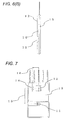
FIG. 7 . - In the present example, each of the elements are arranged within the
circuit package 13 so as to achieve adistance 16 between the physicalquantity sensing element 12 and theheating device 14 < a distance 15 between the airflow sensing element 11 and theheating device 14. Particularly in a case where the physicalquantity sensing element 12 is a humidity sensing element, when condensation occurs in the humidity sensing element, the humidity sensing element continues to sense a state of relative humidity being substantially 100% until the element dries, as described above. Accordingly, it would be effective to heat portions in the vicinity of the humidity sensing element using theheating device 14 to increase the temperature of the circuit package. In this, however, when the heat generated by theheating device 14 is transmitted to the airflow sensing element 11, an air flow sensing error might be generated due to thermal effects. To cope with this, by arranging such that each of the elements are arranged within thecircuit package 13 so as to achieve adistance 16 between the physicalquantity sensing element 12 and theheating device 14 < adistance 16 between the airflow sensing element 11 and theheating device 14, that is, while maintaining the distance between the physicalquantity sensing element 12 and theheating device 14, by separating the distance between the airflow sensing element 11 and theheating device 14, it would be possible to maintain sensing accuracy in physical quantities such as humidity, and at the same time, to reduce air flow sensing errors due to thermal effects, and thus, to provide a highly accurate mass air flow measurement device. - Next, another example of the present invention will be described with reference to
FIGS. 8(A) and8(B) . - In the present example, a
rib 17 or a groove 18 is formed on an upstream side of the physicalquantity sensing element 11, in the air flow direction. Considering the intake air contains water, with this configuration having therib 17 or the groove 18, it is possible to prevent contaminant materials such as dust, oil, and water contained in the intake air from attaching to the sensing section. - As above, embodiments of the present invention have been described. The present invention is not limited to the above-described embodiments but may include various design modifications without departing from the spirit of the present invention described in claims. For example, the above-described embodiments give detailed explanation just to allow the present invention to be clearly understood. Therefore, the present invention is not limited to the case having all of components in the configuration. In addition, a part of configuration of an embodiment can be replaced with a part of configuration of another embodiment. A part or the configuration of another embodiment can be added to a certain embodiment. Furthermore, regarding the portions of the configuration of each of the embodiments, addition, deletion, and replacement from another configuration would be possible.
-
- 1 housing structural component
- 2 cover
- 3 mass air flow measurement device
- 4 main air flow passage
- 5 air flow passage component
- 6 flange
- 7 connector
- 8 measuring section
- 9 bypass passage
- 10 air flow
- 11 air flow sensing element
- 12 physical quantity sensing element
- 13 circuit package
- 14 heating device
- 15 distance between air flow sensing element and heating device
- 16 distance between physical quantity sensing element and heating device
- 17 rib
- 18 groove
Claims (9)
- A mass air flow measurement device comprising:an air flow sensing element that senses air flow;a physical quantity sensing element that senses at least one of humidity and pressure; anda circuit package incorporating a circuit that processes an output signal of the air flow sensing element or an output signal of the physical quantity sensing element,wherein the air flow sensing element and the physical quantity sensing element are arranged in the same circuit package.
- The mass air flow measurement device according to claim 1,
wherein at least one of the air flow sensing element and the physical quantity sensing element is formed of a plastic package component. - The mass air flow measurement device according to claim 1,
wherein the air flow sensing element and the physical quantity sensing element are arranged within the circuit package so as to be perpendicular to a flowing direction of the air passing through a main air flow passage. - The mass air flow measurement device according to claim 1,
wherein the physical quantity sensing element is arranged on a side of a connector rather than on a side of the air flow sensing element. - The mass air flow measurement device according to claim 1,
wherein the physical quantity sensing element is arranged along a same line. - The mass air flow measurement device according to claim 1,
wherein, in the circuit package, a heating device is arranged in the vicinity of the physical quantity sensing element. - The mass air flow measurement device according to claim 6,
wherein the heating device is formed with a chip resistor or a thermistor. - The mass air flow measurement device according to claim 6,
wherein, when a distance between the physical quantity sensing element and the heating device is defined as L1, and a distance between the air flow sensing element and the heating device is defined as L2, a relationship of L1 < L2 is satisfied. - The mass air flow measurement device according to claim 1,
wherein, in the circuit package, a rib or a groove is formed on at least one of upstream and downstream sides of the physical quantity sensing element, in the air flow direction.
Applications Claiming Priority (2)
| Application Number | Priority Date | Filing Date | Title |
|---|---|---|---|
| JP2013226132 | 2013-10-31 | ||
| PCT/JP2014/073427 WO2015064213A1 (en) | 2013-10-31 | 2014-09-05 | Airflow measurement device |
Publications (2)
| Publication Number | Publication Date |
|---|---|
| EP3064906A1 true EP3064906A1 (en) | 2016-09-07 |
| EP3064906A4 EP3064906A4 (en) | 2017-03-08 |
Family
ID=53003826
Family Applications (1)
| Application Number | Title | Priority Date | Filing Date |
|---|---|---|---|
| EP14857200.1A Withdrawn EP3064906A4 (en) | 2013-10-31 | 2014-09-05 | Airflow measurement device |
Country Status (5)
| Country | Link |
|---|---|
| US (1) | US20160252378A1 (en) |
| EP (1) | EP3064906A4 (en) |
| JP (1) | JP6200962B2 (en) |
| CN (1) | CN105683721A (en) |
| WO (1) | WO2015064213A1 (en) |
Families Citing this family (2)
| Publication number | Priority date | Publication date | Assignee | Title |
|---|---|---|---|---|
| WO2018100854A1 (en) * | 2016-11-30 | 2018-06-07 | 日立オートモティブシステムズ株式会社 | Air flow rate measurement device |
| WO2019225073A1 (en) * | 2018-05-22 | 2019-11-28 | 日立オートモティブシステムズ株式会社 | Physical quantity detecting device |
Family Cites Families (11)
| Publication number | Priority date | Publication date | Assignee | Title |
|---|---|---|---|---|
| JPH02103263U (en) * | 1989-02-01 | 1990-08-16 | ||
| JP3335860B2 (en) * | 1997-01-16 | 2002-10-21 | 株式会社日立製作所 | Measuring element for thermal air flow meter and thermal air flow meter |
| JP4381630B2 (en) * | 2001-06-06 | 2009-12-09 | 株式会社日立製作所 | Resin-sealed module device for automobile control |
| JP4797771B2 (en) * | 2006-04-20 | 2011-10-19 | 株式会社デンソー | SENSOR DEVICE HAVING MEMBRANE AND MANUFACTURING METHOD THEREOF |
| JP4882732B2 (en) | 2006-12-22 | 2012-02-22 | 株式会社デンソー | Semiconductor device |
| JP5279667B2 (en) | 2008-11-28 | 2013-09-04 | 日立オートモティブシステムズ株式会社 | Thermal air flow sensor |
| JP4929333B2 (en) * | 2009-09-30 | 2012-05-09 | 日立オートモティブシステムズ株式会社 | Sensor structure |
| JP5208099B2 (en) * | 2009-12-11 | 2013-06-12 | 日立オートモティブシステムズ株式会社 | Flow sensor, method for manufacturing the same, and flow sensor module |
| JP2012058044A (en) * | 2010-09-08 | 2012-03-22 | Hitachi Automotive Systems Ltd | Thermal type fluid flow rate measuring device |
| JP5526065B2 (en) * | 2011-03-25 | 2014-06-18 | 日立オートモティブシステムズ株式会社 | Thermal sensor and manufacturing method thereof |
| DE112012005695B4 (en) * | 2012-01-18 | 2021-10-07 | Hitachi Automotive Systems, Ltd. | Thermal flow meter |
-
2014
- 2014-09-05 EP EP14857200.1A patent/EP3064906A4/en not_active Withdrawn
- 2014-09-05 CN CN201480059113.7A patent/CN105683721A/en active Pending
- 2014-09-05 WO PCT/JP2014/073427 patent/WO2015064213A1/en not_active Ceased
- 2014-09-05 JP JP2015544852A patent/JP6200962B2/en not_active Expired - Fee Related
- 2014-09-05 US US15/029,773 patent/US20160252378A1/en not_active Abandoned
Also Published As
| Publication number | Publication date |
|---|---|
| CN105683721A (en) | 2016-06-15 |
| JP6200962B2 (en) | 2017-09-20 |
| US20160252378A1 (en) | 2016-09-01 |
| EP3064906A4 (en) | 2017-03-08 |
| WO2015064213A1 (en) | 2015-05-07 |
| JPWO2015064213A1 (en) | 2017-03-09 |
Similar Documents
| Publication | Publication Date | Title |
|---|---|---|
| JP5279667B2 (en) | Thermal air flow sensor | |
| JP5271997B2 (en) | Intake air temperature sensor | |
| JP5883887B2 (en) | Flow measuring device | |
| CN107101685B (en) | Thermal Flow Meter | |
| US9945706B2 (en) | Thermal-type air flow meter | |
| CN106030258B (en) | Sensor assembly for determining at least one parameter of a fluid medium flowing through a channel | |
| EP3217153B1 (en) | Thermal air flow meter | |
| US20180274964A1 (en) | Physical quantity sensor subassembly and physical quantity measuring device | |
| JP6641820B2 (en) | Flow measurement device | |
| JP6101619B2 (en) | Thermal air flow meter | |
| EP2966417B1 (en) | Thermal-type airflow meter | |
| US9829360B2 (en) | Air flow sensor including a resin-molded protection member for a temperature sensor | |
| US20160252378A1 (en) | Mass Air Flow Measurement Device | |
| JP5814192B2 (en) | Flow measuring device | |
| KR20150145188A (en) | Temperature measuring device for detecting temperature of a flowing fluid medium | |
| JP6033935B2 (en) | Flow measuring device | |
| US20150059467A1 (en) | Oscillator circuit | |
| JP6602744B2 (en) | Sensor device and manufacturing method thereof | |
| US20130019692A1 (en) | Air flow measuring device |
Legal Events
| Date | Code | Title | Description |
|---|---|---|---|
| PUAI | Public reference made under article 153(3) epc to a published international application that has entered the european phase |
Free format text: ORIGINAL CODE: 0009012 |
|
| 17P | Request for examination filed |
Effective date: 20160531 |
|
| AK | Designated contracting states |
Kind code of ref document: A1 Designated state(s): AL AT BE BG CH CY CZ DE DK EE ES FI FR GB GR HR HU IE IS IT LI LT LU LV MC MK MT NL NO PL PT RO RS SE SI SK SM TR |
|
| AX | Request for extension of the european patent |
Extension state: BA ME |
|
| DAX | Request for extension of the european patent (deleted) | ||
| A4 | Supplementary search report drawn up and despatched |
Effective date: 20170206 |
|
| RIC1 | Information provided on ipc code assigned before grant |
Ipc: G01F 15/00 20060101ALN20170131BHEP Ipc: G01F 15/02 20060101ALI20170131BHEP Ipc: G01F 1/696 20060101ALN20170131BHEP Ipc: G01F 1/684 20060101AFI20170131BHEP |
|
| TPAC | Observations filed by third parties |
Free format text: ORIGINAL CODE: EPIDOSNTIPA |
|
| TPAC | Observations filed by third parties |
Free format text: ORIGINAL CODE: EPIDOSNTIPA |
|
| STAA | Information on the status of an ep patent application or granted ep patent |
Free format text: STATUS: EXAMINATION IS IN PROGRESS |
|
| TPAC | Observations filed by third parties |
Free format text: ORIGINAL CODE: EPIDOSNTIPA |
|
| 17Q | First examination report despatched |
Effective date: 20190423 |
|
| STAA | Information on the status of an ep patent application or granted ep patent |
Free format text: STATUS: THE APPLICATION HAS BEEN WITHDRAWN |
|
| 18W | Application withdrawn |
Effective date: 20190809 |