EP3064746A1 - Systems and methods for turbine system operation in low ambient temperatures - Google Patents
Systems and methods for turbine system operation in low ambient temperatures Download PDFInfo
- Publication number
- EP3064746A1 EP3064746A1 EP16158501.3A EP16158501A EP3064746A1 EP 3064746 A1 EP3064746 A1 EP 3064746A1 EP 16158501 A EP16158501 A EP 16158501A EP 3064746 A1 EP3064746 A1 EP 3064746A1
- Authority
- EP
- European Patent Office
- Prior art keywords
- compressor
- fluid
- fuel
- bleed heat
- inlet bleed
- Prior art date
- Legal status (The legal status is an assumption and is not a legal conclusion. Google has not performed a legal analysis and makes no representation as to the accuracy of the status listed.)
- Granted
Links
Images


Classifications
-
- F—MECHANICAL ENGINEERING; LIGHTING; HEATING; WEAPONS; BLASTING
- F01—MACHINES OR ENGINES IN GENERAL; ENGINE PLANTS IN GENERAL; STEAM ENGINES
- F01K—STEAM ENGINE PLANTS; STEAM ACCUMULATORS; ENGINE PLANTS NOT OTHERWISE PROVIDED FOR; ENGINES USING SPECIAL WORKING FLUIDS OR CYCLES
- F01K23/00—Plants characterised by more than one engine delivering power external to the plant, the engines being driven by different fluids
- F01K23/02—Plants characterised by more than one engine delivering power external to the plant, the engines being driven by different fluids the engine cycles being thermally coupled
- F01K23/06—Plants characterised by more than one engine delivering power external to the plant, the engines being driven by different fluids the engine cycles being thermally coupled combustion heat from one cycle heating the fluid in another cycle
- F01K23/10—Plants characterised by more than one engine delivering power external to the plant, the engines being driven by different fluids the engine cycles being thermally coupled combustion heat from one cycle heating the fluid in another cycle with exhaust fluid of one cycle heating the fluid in another cycle
-
- F—MECHANICAL ENGINEERING; LIGHTING; HEATING; WEAPONS; BLASTING
- F02—COMBUSTION ENGINES; HOT-GAS OR COMBUSTION-PRODUCT ENGINE PLANTS
- F02C—GAS-TURBINE PLANTS; AIR INTAKES FOR JET-PROPULSION PLANTS; CONTROLLING FUEL SUPPLY IN AIR-BREATHING JET-PROPULSION PLANTS
- F02C6/00—Plural gas-turbine plants; Combinations of gas-turbine plants with other apparatus; Adaptations of gas-turbine plants for special use
- F02C6/04—Gas-turbine plants providing heated or pressurised working fluid for other apparatus, e.g. without mechanical power output
- F02C6/06—Gas-turbine plants providing heated or pressurised working fluid for other apparatus, e.g. without mechanical power output providing compressed gas
- F02C6/08—Gas-turbine plants providing heated or pressurised working fluid for other apparatus, e.g. without mechanical power output providing compressed gas the gas being bled from the gas-turbine compressor
-
- F—MECHANICAL ENGINEERING; LIGHTING; HEATING; WEAPONS; BLASTING
- F02—COMBUSTION ENGINES; HOT-GAS OR COMBUSTION-PRODUCT ENGINE PLANTS
- F02C—GAS-TURBINE PLANTS; AIR INTAKES FOR JET-PROPULSION PLANTS; CONTROLLING FUEL SUPPLY IN AIR-BREATHING JET-PROPULSION PLANTS
- F02C9/00—Controlling gas-turbine plants; Controlling fuel supply in air- breathing jet-propulsion plants
- F02C9/16—Control of working fluid flow
- F02C9/20—Control of working fluid flow by throttling; by adjusting vanes
- F02C9/22—Control of working fluid flow by throttling; by adjusting vanes by adjusting turbine vanes
-
- F—MECHANICAL ENGINEERING; LIGHTING; HEATING; WEAPONS; BLASTING
- F02—COMBUSTION ENGINES; HOT-GAS OR COMBUSTION-PRODUCT ENGINE PLANTS
- F02C—GAS-TURBINE PLANTS; AIR INTAKES FOR JET-PROPULSION PLANTS; CONTROLLING FUEL SUPPLY IN AIR-BREATHING JET-PROPULSION PLANTS
- F02C9/00—Controlling gas-turbine plants; Controlling fuel supply in air- breathing jet-propulsion plants
- F02C9/48—Control of fuel supply conjointly with another control of the plant
- F02C9/50—Control of fuel supply conjointly with another control of the plant with control of working fluid flow
-
- F—MECHANICAL ENGINEERING; LIGHTING; HEATING; WEAPONS; BLASTING
- F02—COMBUSTION ENGINES; HOT-GAS OR COMBUSTION-PRODUCT ENGINE PLANTS
- F02C—GAS-TURBINE PLANTS; AIR INTAKES FOR JET-PROPULSION PLANTS; CONTROLLING FUEL SUPPLY IN AIR-BREATHING JET-PROPULSION PLANTS
- F02C9/00—Controlling gas-turbine plants; Controlling fuel supply in air- breathing jet-propulsion plants
- F02C9/48—Control of fuel supply conjointly with another control of the plant
- F02C9/50—Control of fuel supply conjointly with another control of the plant with control of working fluid flow
- F02C9/52—Control of fuel supply conjointly with another control of the plant with control of working fluid flow by bleeding or by-passing the working fluid
-
- F—MECHANICAL ENGINEERING; LIGHTING; HEATING; WEAPONS; BLASTING
- F05—INDEXING SCHEMES RELATING TO ENGINES OR PUMPS IN VARIOUS SUBCLASSES OF CLASSES F01-F04
- F05D—INDEXING SCHEME FOR ASPECTS RELATING TO NON-POSITIVE-DISPLACEMENT MACHINES OR ENGINES, GAS-TURBINES OR JET-PROPULSION PLANTS
- F05D2220/00—Application
- F05D2220/70—Application in combination with
- F05D2220/72—Application in combination with a steam turbine
-
- F—MECHANICAL ENGINEERING; LIGHTING; HEATING; WEAPONS; BLASTING
- F05—INDEXING SCHEMES RELATING TO ENGINES OR PUMPS IN VARIOUS SUBCLASSES OF CLASSES F01-F04
- F05D—INDEXING SCHEME FOR ASPECTS RELATING TO NON-POSITIVE-DISPLACEMENT MACHINES OR ENGINES, GAS-TURBINES OR JET-PROPULSION PLANTS
- F05D2220/00—Application
- F05D2220/70—Application in combination with
- F05D2220/75—Application in combination with equipment using fuel having a low calorific value, e.g. low BTU fuel, waste end, syngas, biomass fuel or flare gas
-
- F—MECHANICAL ENGINEERING; LIGHTING; HEATING; WEAPONS; BLASTING
- F05—INDEXING SCHEMES RELATING TO ENGINES OR PUMPS IN VARIOUS SUBCLASSES OF CLASSES F01-F04
- F05D—INDEXING SCHEME FOR ASPECTS RELATING TO NON-POSITIVE-DISPLACEMENT MACHINES OR ENGINES, GAS-TURBINES OR JET-PROPULSION PLANTS
- F05D2270/00—Control
- F05D2270/01—Purpose of the control system
- F05D2270/05—Purpose of the control system to affect the output of the engine
-
- F—MECHANICAL ENGINEERING; LIGHTING; HEATING; WEAPONS; BLASTING
- F05—INDEXING SCHEMES RELATING TO ENGINES OR PUMPS IN VARIOUS SUBCLASSES OF CLASSES F01-F04
- F05D—INDEXING SCHEME FOR ASPECTS RELATING TO NON-POSITIVE-DISPLACEMENT MACHINES OR ENGINES, GAS-TURBINES OR JET-PROPULSION PLANTS
- F05D2270/00—Control
- F05D2270/01—Purpose of the control system
- F05D2270/08—Purpose of the control system to produce clean exhaust gases
- F05D2270/083—Purpose of the control system to produce clean exhaust gases by monitoring combustion conditions
- F05D2270/0831—Purpose of the control system to produce clean exhaust gases by monitoring combustion conditions indirectly, at the exhaust
-
- F—MECHANICAL ENGINEERING; LIGHTING; HEATING; WEAPONS; BLASTING
- F05—INDEXING SCHEMES RELATING TO ENGINES OR PUMPS IN VARIOUS SUBCLASSES OF CLASSES F01-F04
- F05D—INDEXING SCHEME FOR ASPECTS RELATING TO NON-POSITIVE-DISPLACEMENT MACHINES OR ENGINES, GAS-TURBINES OR JET-PROPULSION PLANTS
- F05D2270/00—Control
- F05D2270/30—Control parameters, e.g. input parameters
- F05D2270/303—Temperature
-
- F—MECHANICAL ENGINEERING; LIGHTING; HEATING; WEAPONS; BLASTING
- F05—INDEXING SCHEMES RELATING TO ENGINES OR PUMPS IN VARIOUS SUBCLASSES OF CLASSES F01-F04
- F05D—INDEXING SCHEME FOR ASPECTS RELATING TO NON-POSITIVE-DISPLACEMENT MACHINES OR ENGINES, GAS-TURBINES OR JET-PROPULSION PLANTS
- F05D2270/00—Control
- F05D2270/30—Control parameters, e.g. input parameters
- F05D2270/313—Air temperature
-
- F—MECHANICAL ENGINEERING; LIGHTING; HEATING; WEAPONS; BLASTING
- F05—INDEXING SCHEMES RELATING TO ENGINES OR PUMPS IN VARIOUS SUBCLASSES OF CLASSES F01-F04
- F05D—INDEXING SCHEME FOR ASPECTS RELATING TO NON-POSITIVE-DISPLACEMENT MACHINES OR ENGINES, GAS-TURBINES OR JET-PROPULSION PLANTS
- F05D2270/00—Control
- F05D2270/30—Control parameters, e.g. input parameters
- F05D2270/335—Output power or torque
-
- Y—GENERAL TAGGING OF NEW TECHNOLOGICAL DEVELOPMENTS; GENERAL TAGGING OF CROSS-SECTIONAL TECHNOLOGIES SPANNING OVER SEVERAL SECTIONS OF THE IPC; TECHNICAL SUBJECTS COVERED BY FORMER USPC CROSS-REFERENCE ART COLLECTIONS [XRACs] AND DIGESTS
- Y02—TECHNOLOGIES OR APPLICATIONS FOR MITIGATION OR ADAPTATION AGAINST CLIMATE CHANGE
- Y02E—REDUCTION OF GREENHOUSE GAS [GHG] EMISSIONS, RELATED TO ENERGY GENERATION, TRANSMISSION OR DISTRIBUTION
- Y02E20/00—Combustion technologies with mitigation potential
- Y02E20/14—Combined heat and power generation [CHP]
Definitions
- the subject matter disclosed herein relates to power generation systems. Specifically, the embodiments described herein relate to controlling a turbine system in low ambient temperatures.
- a compressor may be used to compress a fluid (e.g., air) prior to mixing the fluid with fuel for combustion.
- a fluid e.g., air
- the power generation system may be configured to observe and maintain the operating limit of the compressor, particularly when the power generation system uses a low British Thermal Unit (BTU) fuel.
- BTU fuels include fuels that may have large concentrations of inert gases, synthetic gases, waste gases, and biomass gases.
- the power generation system may be configured to intentionally under-fire. That is, the fuel flow is often reduced to account for reduced compression due to the design limits of the compressor in low ambient temperatures. Reducing the fuel flow may in turn lead to lower firing temperatures for the power generation system.
- intentionally under-firing the power generation system may also result in output loss, in terms of the power generated by the power generation system as well as a loss of exhaust energy which may be captured and used by other components, such as a heat steam recovery generator (HSRG). It would be beneficial to operate power generation systems in low ambient temperatures, particularly when utilizing low BTU fuels, such that the system maintains the compressor limits while minimizing intentional under-fire.
- HSRG heat steam recovery generator
- a system in a first embodiment, includes a fluid intake system configured to intake a fluid and a compressor system fluidly coupled to the fluid intake system and configured to compress the fluid.
- the system also includes a combustor system fluidly coupled to the compressor and configured to combust a fuel mixed with the fluid, as wells as a turbine system fluidly coupled to the combustor and configured to rotate a shaft mechanically coupled to a load.
- the system includes an inlet bleed heat system fluidly coupled to the compressor and to the fluid intake system and configured to direct a compressor fluid from the compressor into the fluid intake system.
- the system also includes a controller operatively coupled to the inlet bleed heat system and configured to sense an exhaust temperature of the turbine system. The controller is configured to adjust the compressor fluid flow via the inlet bleed heat system based on the exhaust temperature.
- a system in a second embodiment, includes a controller communicatively coupled to a compressor.
- the controller is configured to sense the exhaust temperature of a gas turbine system, wherein the gas turbine system is fluidly coupled to the compressor.
- the controller is also configured to derive a setpoint based on the sensed exhaust temperature. Further, the controller is configured to actuate an inlet bleed heat valve based on the derived setpoint and an ambient temperature.
- the inlet bleed heat valve directs a compressor fluid from the compressor into a fluid intake system which is fluidly coupled to the compressor upstream of the compressor and configured to intake a fluid.
- a non-transitory, computer-readable medium includes executable code having instructions.
- the instructions are configured to receive an input corresponding to an exhaust temperature of a turbine system and retrieve a baseload control function for a compressor system coupled to the turbine system.
- the instructions are also configured to retrieve data corresponding to a design limit of the compressor system and determine the difference between the operating level of the compressor system and the design limit of the compressor system.
- the instructions are configured to calculate an exhaust temperature bias based on the baseload control function and the exhaust temperature.
- the instructions are configured to actuate an inlet bleed heat valve based on the exhaust temperature bias and the difference between the operating level of the compressor system and the design limit of the compressor system.
- the inlet bleed heat valve directs a compressor fluid from the compressor system into a fluid intake system fluidly which is coupled to the compressor system upstream of the compressor system and configured to intake a fluid.
- the articles “a,” “an,” “the,” and “said” are intended to mean that there are one or more of the elements.
- the terms “comprising,” “including,” and “having” are intended to be inclusive and mean that there may be additional elements other than the listed elements.
- Present embodiments relate to systems and methods for maintaining compressor operating limits and system output in power generation systems, such as gas turbine systems.
- the techniques described herein use inlet bleed heat to maintain compressor operating limits in low ambient temperatures. More specifically, the techniques described herein relate to using inlet bleed heat to operate a compressor in low ambient temperatures, as well as adjusting the fuel schedule of the power generation system containing the compressor based on, for example, the inlet bleed heat adjustments.
- the compressor may operate at the design limits during low ambient temperatures without a reduction in compression.
- the power generation system may operate without intentionally under-firing (e.g., reducing the fuel flow) to account for reduced compression due to low ambient temperatures.
- the power generation system may remain at the desired firing temperature levels, increasing the output and exhaust energy of the power generation system in low ambient temperatures.
- FIG. 1 illustrates a power generation system 10 that may be used to provide power to a load, such as an electric generator, a mechanical load, and so on.
- the power generation system 10 includes a fuel supply system 12, which includes a fuel repository 14 and a fuel control valve 16 that controls the amount of fuel supplied to the power generation system 10.
- the power generation system 10 further includes a fluid intake system 18 coupled to a fluid source 20 and a fluid control valve 22 that controls the amount of fluid supplied to the power generation system 10.
- the power generation system 10 also includes a turbine system 24 which in turn includes a compressor 26, a combustion system 28 containing one or more fuel nozzles 30, a turbine 32, and an exhaust section 34. As shown in FIG.
- the exhaust section 34 may include a heat recovery steam generator (HRSG) 36.
- HRSG heat recovery steam generator
- a control system 38 oversees certain aspects of the power generation system 10.
- the control system 36 may work in conjunction with sensors 40 and actuators 42 to monitor and adjust the operation of the power generation system 10.
- the sensors 40 may include temperature sensors, oxygen sensor, pressure sensors, speed sensors, fuel flow sensors, fuel type sensors, and the like, while the fuel control valve 16 and the fluid control valve 22 are examples of actuators 42.
- the control system 38 may also include a cold day system 44 to monitor and adjust the performance of the power generation system 10 based on the design limits of the compressor 26 and which is described in further detail below.
- the fuel supply system 12 may provide fuel to the turbine system 24 via the fuel control valve 16.
- the fluid intake system 18 may provide oxidant fluid (e.g., air) to the compressor 26 via the fluid control valve 22.
- the fluid is then compressed before being sent to the combustion system 28.
- the fuel nozzle(s) 30 inject fuel that mixes with the compressed fluid to create a fluid-fuel mixture that combusts before flowing into the turbine 32.
- the combusted fluid-fuel mixture drives one or more stages of the turbine 32, which may in turn drive a shaft connected to a load 46.
- the load 46 may be a generator to produce electricity.
- the combusted gases exit the turbine 32 and vent as exhaust gases through the exhaust section 34.
- the exhaust gases pass through the HRSG 36, which recovers the heat from the exhaust gases to produce steam.
- the depicted power generation system 10 may be a combined cycle or co-generation system, such that the steam is used to drive a downstream steam turbine (i.e., a combined cycle system) or for a co-generation process.
- the exhaust gases may pass through other components within the exhaust section 34, such as catalytic converter systems.
- control system 38 may control certain aspects of the operation of the power generation system 10.
- the control system 38 includes memory 48, a processor 50, and a hardware interface 52 for interacting with the sensors 40 and the actuators 42, as depicted in FIG. 2 .
- the processor 50 and/or other data processing circuitry may be operably coupled to memory 48 to retrieve and execute instructions for managing the power generation system 10.
- these instructions may be encoded in programs or software that are stored in memory 48, which may be an example of a tangible, non-transitory computer-readable medium, and may be accessed and executed by the processor 50 to allow for the presently disclosed techniques to be performed.
- the memory 48 may be a mass storage device, a FLASH memory device, removable memory, or any other non-transitory computer-readable medium. Additionally and/or alternatively, the instructions may be stored in an additional suitable article of manufacture that includes at least one tangible, non-transitory computer-readable medium that at least collectively stores these instructions or routines in a manner similar to the memory 48 as described above.
- the control system 38 may also communicate with the sensors 40 and the actuators 42 via the hardware interface 52, as stated above, including through wired and wireless conduits.
- control system 38 may be a distributed control system (DCS), such that each component or a group of components may include or be associated with a controller for controlling the specific component(s).
- each controller may contain memory, a processor, and a hardware interface similar to that of the control system 38 as described above. Further, in such embodiments, the controllers may include a communicative link to other controllers to coordinate decision-making.
- the compressor 26 may include several sets of blades 54 that are arranged in stages or rows around a rotor or shaft 56.
- the compressor 20 is coupled to the fluid intake system 18 via an intake shaft 58, and to the combustion system via an output shaft 60.
- a set of inlet guide vanes 62 controls the amount of fluid (e.g., air) that enters the compressor 26 at any given time, in contrast to the fluid control valve 22, which controls the amount of fluid delivered from the fluid intake system 18 to the compressor 26.
- the angles of the blades of the inlet guide vanes 62 may determine the amount of fluid that enters the compressor 26.
- angles of the inlet guide vanes 62 may be controlled by the control system 38, or, as described in further detail below, by the cold day system 44.
- the fluid travels through the compressor 26 and becomes compressed. That is, each set of blades 54 rotatively moves the fluid through the compressor 26 while reducing the volume of the fluid, thereby compressing the fluid. Compressing the fluid generates heat and pressure.
- the compressor 26 may be configured to re-circulate the compressor discharge (e.g., discharge fluid) back into the intake shaft 58 via an inlet manifold 64.
- the recirculated compressor discharge fluid is commonly referred to as "inlet bleed heat," and may be used for a variety of functions, such as reducing icing on various inlets on the compressor 26 due to low ambient temperatures and protecting the compressor 26 when the inlet guide vanes 62 are closed.
- inlet bleed heat systems there are several commercially available inlet bleed heat systems that can be added to compressors such as the compressor 26 and incorporated into the operating software (e.g., control system 38) of the power generation system 10.
- the techniques described herein apply the inlet bleed's temperature and pressure characteristics to more efficiently operate in certain environments, such as low ambient temperatures, for example, without a substantial reduction in compression.
- the control system 38 oversees the operation of the power generation system 10, and ensures that each component operates within its design limits. To do so, the control system 38 may have different components and processes for monitoring each component, similar to the scheme for a distributed control system as described above.
- One such aspect of the control system 38 may be the cold day system 44.
- the cold day system 44 may monitor the operation of the compressor 38 and, in some embodiments, the fuel system 12, when the power generation system 10 operates during low ambient temperatures, and may control certain aspects of the system 10 based on the monitoring.
- the cold day system 44 may redirect a portion of the inlet bleed heat generated by the compressor 26 to be added to the intake fluid for the compressor 26, and may control the fuel scheduling based on the amount of inlet bleed heat fed into the compressor 26.
- utilizing the inlet bleed heat as part of the intake fluid and adjusting the fuel scheduling may enable the compressor 26 to operate at desired margins (e.g., safety margins) of the design limits during low ambient temperatures. This, in turn, may reduce the amount of intentional under-firing of the power generation system 10 to account for compressor safety margins during low ambient temperatures, which subsequently improves the output of the power generation system 10 during low ambient temperatures. Particularly, the embodiments described herein may also improve the output of power generation systems 10 that utilize low BTU fuels during low ambient temperatures.
- the embodiments described herein may be applied retroactively to power generation system 10 by utilizing a commercially available inlet bleed heat system and making modifications to the control system 38 as necessary.
- the modifications may be software only, while in other power plants, the modifications may include hardware and software modifications.
- the cold day system 44 is part of the control system 38, and thus uses the sensors 40, actuators 42, memory 48, and processor 50, as described above.
- the cold day system 44 may be configured on a controller as part of a distributed control system.
- the cold day system 44 may be separate from the control system 38, and may communicate and work in conjunction with the control system 38 as necessary.
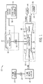
- FIG. 4 the figure illustrates a schematic diagram of embodiments of the cold day system 44 communicatively coupled to the compressor 26 and combustor 28.
- the cold day system 44 oversees the operation of the compressor 26, as well as other components of the system 10.
- the cold day system 44 may utilize a baseload control curve 66 (or similar derivation) that represents normal operating procedures for the compressor 26 (i.e., no inlet bleed heat addition at low ambient temperatures).
- the baseload control curve 66 corresponds to a compressor pressure ratio function, which compares the pressure of the fluid exiting the compressor 26 to that of the fluid entering the compressor 26.
- other baseload control curves 66 that quantify the operation of the compressor 26 may be used.
- the baseload control curve 66 may be stored or generated during operation by either the cold day system 44 or the control system 38. In other embodiments, the baseload control curve 66 may be calculated offline and uploaded to the cold day system 44 or the control system 38.
- the cold day system 44 determines an operating difference 68 between the design limits 70 of the compressor 26 and the current operating level 72 of the compressor 26.
- the data representing the design limits 70 may be stored on the memory 48 in embodiments in which the cold day system 44 is part of the control system 38.
- the cold day system 44 may be configured to retrieve the design limits 70 from the control system 38, or from memory in the cold day system 44.
- either the cold day system 44 or the control system 38 may be configured to retrieve the design limits 70 from another component or system, such as a data repository containing information about the various components of the power generation system 10.
- the current operating level 72 may be determined based on data received from the sensors 40 disposed in or around the compressor 26, such as the temperature or pressure of the fluid exiting the compressor 26.
- the cold day system 44 may determine the operating difference 68 only when activated by a control signal. For instance, the cold day system 44 may only determine the operating difference 68 if the cold day system 44 or the control system 38 has determined that the ambient temperature is below a pre-set threshold.
- the cold day system 44 may control an inlet bleed heat valve 74 to add inlet bleed heat to the intake fluid of the compressor 20.
- inlet bleed heat which, as mentioned above, is included in a portion of the fluid generated by compressing fluid
- the temperature of the intake fluid increases as a whole. This temperature increase, in turn, increases the amount of compression of the fluid, regardless of the operating level of the compressor 26. That is, if the compressor 26 receives a fluid at a first temperature and then a second fluid at a second higher temperature, the compression at the lower temperature will be less than the compression the higher temperature, regardless of any change in the operation of the compressor 20.
- the control system 38 does not need to reduce fuel flow in order to account for a decrease in compression. Accordingly, the power generation system 10 can then maintain the desired firing temperatures during low ambient temperatures. As such, the power generation system 10 may have increased output compared to other power generation systems in which firing temperature suppression is used to maintain compressor operating limits during low ambient temperatures. The power generation system 10 may also have increased exhaust energy, which may be used by downstream components, such as the HRSG 30.
- inlet bleed heat is added to the fluid intake, the temperature of the compressed fluid rises, as mentioned above. Subsequently, the compressor pressure ratio function, and other types of baseload control curves 66, shift based on the inlet bleed heat addition. Additionally, the exhaust gas temperature of the turbine system 24 changes relative to the exhaust gas temperature of the turbine system 24 when no inlet bleed heat is added. Based on the shifted baseload control curves 66, the cold day system 44 then calculates an exhaust temperature bias 76 that represents the change in the exhaust gas temperature due to the inlet bleed heat addition. The cold day system 44 then adjusts the inlet bleed heat addition or the fuel schedule for the turbine system 24 to maintain the desired firing temperature of the turbine system 24 while observing the design limits 70 of the compressor 26.
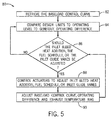
- FIG. 5 the figure depicts a flow chart of an embodiment of a process 80 suitable for adding inlet bleed heat during low ambient temperature conditions.
- the process 80 may be implemented as computer instructions stored in memory and executable by the cold day system 44.
- the cold day system 44 may execute for the instructions to better maintain the design limits 70 of the compressor 26 during operation.
- the process 80 is described below in detail, the process 80 may include other steps not shown in FIG. 5 . Additionally, the steps illustrated may be performed concurrently or in a different order.
- the process 80 may be stored in the memory 40 and executed by the processor 42, as described above.
- the cold day system 44 may retrieve the baseload control curve 66, which may correspond to the compressor pressure ratio function, or any other control function that quantifies the operation of the compressor 26.
- the cold day system 44 may retrieve the baseload control curve 66 from the memory 40, the control system 38, or an external system such as a data repository. Further, in other embodiments, the cold day system 44 may be configured to generate the baseload control curve 66 when the power generation system 10 is offline or during operation, or the curve 66 may be generated by the manufacturer and stored for use during system 10 operations.
- the cold day system 44 compares the design limits 70 of the compressor 26 to the current operating level 72 of the compressor 26 to generate the operating difference 68.
- the cold day system 44 may retrieve the design limits 70 from the memory 40, the control system 38, or an external system such as a data repository.
- the current operating level 72 (e.g., pressure, temperature, flow, speed, compression ratio) may be determined based on the data from the sensors 40.
- the current operating level 72 may be determined by the control system 38, and the data passed to the cold day system 44.
- the cold day system 44 may be configured to determine the operating difference 68 only upon receipt of an activation signal.
- the cold day system 44 determines whether to adjust the amount of inlet bleed heat addition to the fluid intake of the compressor 26 or adjust the fuel schedule of the turbine system 24 based on the baseload control curve 66, the operating difference 68, and the exhaust temperature bias 76, if available. Further, in some embodiments, the cold day system 44 may also determine whether to adjust the inlet guide vanes 62 instead. If the cold day system 44 decides to adjust one of the three parameters, then it may proceed to block 88, which is described in detail further below. If not, then the cold day system 44 returns to generating the operating difference 68 at block 84.
- the cold day system 44 adjusts the inlet bleed heat addition, the fuel schedule, and/or the inlet guide vanes 62 as determined in block 86. To do so, the cold day system 44 actuates the inlet bleed heat valve 74, the fuel control valve 16, or the inlet guide vanes 62. In some embodiments (e.g., in a distributed control system), the cold day system 44 may send a control signal to the control system 38 to actuate any of the inlet bleed heat valve 74, the fuel control valve 16, or the inlet guide vanes 62.
- the cold day system 44 determines any changes to the control functions or parameters. That is, at block 90, the cold day system 44 may determine any shifts in the baseload control curve 66, the new operating level 72 of the compressor 26 and, subsequently, the operating difference 68, or the exhaust temperature bias 76. The cold day system 44 may then return to determining adjustments for the inlet bleed heat addition, the fuel schedule, or the inlet guide vanes at block 86.
- inventions include systems and methods for operating a power generation system during low ambient temperatures. Certain embodiments may enable components of the power generation system to operate at design limits during low ambient temperatures without reducing the output of the power generation system.
- the present cold day system may add inlet bleed heat from the compressor to the fluid intake of the compressor, which may allow the compressor to operate at design limits during low ambient temperatures while producing the desired amount of compression. Accordingly, the present power generation system does not have to intentionally under-fire to account for reduced compression, which subsequently increases the output of the power generation system during low ambient temperatures.
- the present cold day system may be applied retroactively to power generation systems by utilizing commercially available inlet bleed heat systems and modifications to the control system of the power generation system.
- the technical effects and technical problems in the specification are exemplary and not limiting. It should be noted that the embodiments described in the specification may have other technical effects and can solve other technical problems.
Landscapes
- Engineering & Computer Science (AREA)
- Chemical & Material Sciences (AREA)
- Combustion & Propulsion (AREA)
- Mechanical Engineering (AREA)
- General Engineering & Computer Science (AREA)
- Physics & Mathematics (AREA)
- Fluid Mechanics (AREA)
- Engine Equipment That Uses Special Cycles (AREA)
Abstract
Description
- The subject matter disclosed herein relates to power generation systems. Specifically, the embodiments described herein relate to controlling a turbine system in low ambient temperatures.
- In a power generation system, such as a gas turbine system, a compressor may be used to compress a fluid (e.g., air) prior to mixing the fluid with fuel for combustion. In low ambient temperatures, the power generation system may be configured to observe and maintain the operating limit of the compressor, particularly when the power generation system uses a low British Thermal Unit (BTU) fuel. Low BTU fuels include fuels that may have large concentrations of inert gases, synthetic gases, waste gases, and biomass gases.
- To maintain the operating limits of the compressor in low ambient temperature conditions, the power generation system may be configured to intentionally under-fire. That is, the fuel flow is often reduced to account for reduced compression due to the design limits of the compressor in low ambient temperatures. Reducing the fuel flow may in turn lead to lower firing temperatures for the power generation system. However, intentionally under-firing the power generation system may also result in output loss, in terms of the power generated by the power generation system as well as a loss of exhaust energy which may be captured and used by other components, such as a heat steam recovery generator (HSRG). It would be beneficial to operate power generation systems in low ambient temperatures, particularly when utilizing low BTU fuels, such that the system maintains the compressor limits while minimizing intentional under-fire.
- Certain embodiments commensurate in scope with the originally claimed invention are summarized below. These embodiments are not intended to limit the scope of the claimed invention, but rather these embodiments are intended only to provide a brief summary of possible forms of the invention. Indeed, the invention may encompass a variety of forms that may be similar to or different from the embodiments set forth below.
- In a first embodiment, a system includes a fluid intake system configured to intake a fluid and a compressor system fluidly coupled to the fluid intake system and configured to compress the fluid. The system also includes a combustor system fluidly coupled to the compressor and configured to combust a fuel mixed with the fluid, as wells as a turbine system fluidly coupled to the combustor and configured to rotate a shaft mechanically coupled to a load. Further, the system includes an inlet bleed heat system fluidly coupled to the compressor and to the fluid intake system and configured to direct a compressor fluid from the compressor into the fluid intake system. The system also includes a controller operatively coupled to the inlet bleed heat system and configured to sense an exhaust temperature of the turbine system. The controller is configured to adjust the compressor fluid flow via the inlet bleed heat system based on the exhaust temperature.
- In a second embodiment, a system includes a controller communicatively coupled to a compressor. The controller is configured to sense the exhaust temperature of a gas turbine system, wherein the gas turbine system is fluidly coupled to the compressor. The controller is also configured to derive a setpoint based on the sensed exhaust temperature. Further, the controller is configured to actuate an inlet bleed heat valve based on the derived setpoint and an ambient temperature. The inlet bleed heat valve directs a compressor fluid from the compressor into a fluid intake system which is fluidly coupled to the compressor upstream of the compressor and configured to intake a fluid.
- In a third embodiment, a non-transitory, computer-readable medium includes executable code having instructions. The instructions are configured to receive an input corresponding to an exhaust temperature of a turbine system and retrieve a baseload control function for a compressor system coupled to the turbine system. The instructions are also configured to retrieve data corresponding to a design limit of the compressor system and determine the difference between the operating level of the compressor system and the design limit of the compressor system. Further, the instructions are configured to calculate an exhaust temperature bias based on the baseload control function and the exhaust temperature. The instructions are configured to actuate an inlet bleed heat valve based on the exhaust temperature bias and the difference between the operating level of the compressor system and the design limit of the compressor system. The inlet bleed heat valve directs a compressor fluid from the compressor system into a fluid intake system fluidly which is coupled to the compressor system upstream of the compressor system and configured to intake a fluid.
- These and other features, aspects, and advantages of the present invention will become better understood when the following detailed description is read with reference to the accompanying drawings in which like characters represent like parts throughout the drawings, wherein:
-
FIG. 1 is a schematic view of a power generation system, in accordance with an embodiment of the present approach; -
FIG. 2 is a block diagram of a control system within the power generation system ofFIG. 1 , in accordance with an embodiment of the present approach; -
FIG. 3 is a cross-sectional view of a compressor within the power generation system ofFIG. 1 , in accordance with an embodiment of the present approach; -
FIG. 4 is a schematic view of a cold day system included in the power generation system ofFIG. 1 , in accordance with an embodiment of the present approach; and -
FIG. 5 is a flow chart illustrating a process for operating the cold day system ofFIG. 4 , in accordance with an embodiment of the present approach. - One or more specific embodiments of the present invention will be described below. In an effort to provide a concise description of these embodiments, all features of an actual implementation may not be described in the specification. It should be appreciated that in the development of any such actual implementation, as in any engineering or design project, numerous implementation-specific decisions must be made to achieve the developers' specific goals, such as compliance with system-related and business-related constraints, which may vary from one implementation to another. Moreover, it should be appreciated that such a development effort might be complex and time consuming, but would nevertheless be a routine undertaking of design, fabrication, and manufacture for those of ordinary skill having the benefit of this disclosure.
- When introducing elements of various embodiments of the present invention, the articles "a," "an," "the," and "said" are intended to mean that there are one or more of the elements. The terms "comprising," "including," and "having" are intended to be inclusive and mean that there may be additional elements other than the listed elements. When a set of guide vanes is described as "closed," it is intended to mean that the blades of the guide vanes are positioned at a relatively small angle. When a set of guide vanes are described as "open," it is intended to mean that the blades of the guide vanes are positioned at a relatively large angle.
- Present embodiments relate to systems and methods for maintaining compressor operating limits and system output in power generation systems, such as gas turbine systems. Specifically, the techniques described herein use inlet bleed heat to maintain compressor operating limits in low ambient temperatures. More specifically, the techniques described herein relate to using inlet bleed heat to operate a compressor in low ambient temperatures, as well as adjusting the fuel schedule of the power generation system containing the compressor based on, for example, the inlet bleed heat adjustments. By utilizing inlet bleed heat to operate the compressor and adjusting the fuel schedule accordingly, the compressor may operate at the design limits during low ambient temperatures without a reduction in compression. As such, the power generation system may operate without intentionally under-firing (e.g., reducing the fuel flow) to account for reduced compression due to low ambient temperatures. As a result, the power generation system may remain at the desired firing temperature levels, increasing the output and exhaust energy of the power generation system in low ambient temperatures.
- With the foregoing in mind,
FIG. 1 illustrates apower generation system 10 that may be used to provide power to a load, such as an electric generator, a mechanical load, and so on. Thepower generation system 10 includes afuel supply system 12, which includes afuel repository 14 and afuel control valve 16 that controls the amount of fuel supplied to thepower generation system 10. Thepower generation system 10 further includes afluid intake system 18 coupled to afluid source 20 and afluid control valve 22 that controls the amount of fluid supplied to thepower generation system 10. Thepower generation system 10 also includes aturbine system 24 which in turn includes acompressor 26, acombustion system 28 containing one ormore fuel nozzles 30, aturbine 32, and anexhaust section 34. As shown inFIG. 1 , theexhaust section 34 may include a heat recovery steam generator (HRSG) 36. Further, acontrol system 38 oversees certain aspects of thepower generation system 10. In particular, thecontrol system 36 may work in conjunction withsensors 40 andactuators 42 to monitor and adjust the operation of thepower generation system 10. For instance, thesensors 40 may include temperature sensors, oxygen sensor, pressure sensors, speed sensors, fuel flow sensors, fuel type sensors, and the like, while thefuel control valve 16 and thefluid control valve 22 are examples ofactuators 42. Thecontrol system 38 may also include acold day system 44 to monitor and adjust the performance of thepower generation system 10 based on the design limits of thecompressor 26 and which is described in further detail below. - During operation of the
power generation system 10, thefuel supply system 12 may provide fuel to theturbine system 24 via thefuel control valve 16. Similarly, thefluid intake system 18 may provide oxidant fluid (e.g., air) to thecompressor 26 via thefluid control valve 22. The fluid is then compressed before being sent to thecombustion system 28. Within thecombustion system 28, the fuel nozzle(s) 30 inject fuel that mixes with the compressed fluid to create a fluid-fuel mixture that combusts before flowing into theturbine 32. The combusted fluid-fuel mixture drives one or more stages of theturbine 32, which may in turn drive a shaft connected to aload 46. For example, theload 46 may be a generator to produce electricity. The combusted gases exit theturbine 32 and vent as exhaust gases through theexhaust section 34. In the depicted embodiment, the exhaust gases pass through theHRSG 36, which recovers the heat from the exhaust gases to produce steam. That is, the depictedpower generation system 10 may be a combined cycle or co-generation system, such that the steam is used to drive a downstream steam turbine (i.e., a combined cycle system) or for a co-generation process. Additionally or alternatively, the exhaust gases may pass through other components within theexhaust section 34, such as catalytic converter systems. - As mentioned above, the
control system 38 may control certain aspects of the operation of thepower generation system 10. Thecontrol system 38 includesmemory 48, aprocessor 50, and ahardware interface 52 for interacting with thesensors 40 and theactuators 42, as depicted inFIG. 2 . As depicted, theprocessor 50 and/or other data processing circuitry may be operably coupled tomemory 48 to retrieve and execute instructions for managing thepower generation system 10. For example, these instructions may be encoded in programs or software that are stored inmemory 48, which may be an example of a tangible, non-transitory computer-readable medium, and may be accessed and executed by theprocessor 50 to allow for the presently disclosed techniques to be performed. Thememory 48 may be a mass storage device, a FLASH memory device, removable memory, or any other non-transitory computer-readable medium. Additionally and/or alternatively, the instructions may be stored in an additional suitable article of manufacture that includes at least one tangible, non-transitory computer-readable medium that at least collectively stores these instructions or routines in a manner similar to thememory 48 as described above. Thecontrol system 38 may also communicate with thesensors 40 and theactuators 42 via thehardware interface 52, as stated above, including through wired and wireless conduits. - In some embodiments, the
control system 38 may be a distributed control system (DCS), such that each component or a group of components may include or be associated with a controller for controlling the specific component(s). In these embodiments, each controller may contain memory, a processor, and a hardware interface similar to that of thecontrol system 38 as described above. Further, in such embodiments, the controllers may include a communicative link to other controllers to coordinate decision-making. - Turning now to
FIG. 3 , thecompressor 26 may include several sets ofblades 54 that are arranged in stages or rows around a rotor orshaft 56. Thecompressor 20 is coupled to thefluid intake system 18 via anintake shaft 58, and to the combustion system via anoutput shaft 60. A set ofinlet guide vanes 62 controls the amount of fluid (e.g., air) that enters thecompressor 26 at any given time, in contrast to thefluid control valve 22, which controls the amount of fluid delivered from thefluid intake system 18 to thecompressor 26. In particular, the angles of the blades of theinlet guide vanes 62 may determine the amount of fluid that enters thecompressor 26. When the angles of the blades are relatively small (i.e., "substantially closed") less fluid is received, but when the angles of the blades are relatively large (i.e., "substantially open") more fluid is received. The angles of theinlet guide vanes 62 may be controlled by thecontrol system 38, or, as described in further detail below, by thecold day system 44. - During operation, the fluid travels through the
compressor 26 and becomes compressed. That is, each set ofblades 54 rotatively moves the fluid through thecompressor 26 while reducing the volume of the fluid, thereby compressing the fluid. Compressing the fluid generates heat and pressure. In the present embodiments, thecompressor 26 may be configured to re-circulate the compressor discharge (e.g., discharge fluid) back into theintake shaft 58 via aninlet manifold 64. The recirculated compressor discharge fluid is commonly referred to as "inlet bleed heat," and may be used for a variety of functions, such as reducing icing on various inlets on thecompressor 26 due to low ambient temperatures and protecting thecompressor 26 when theinlet guide vanes 62 are closed. Accordingly, there are several commercially available inlet bleed heat systems that can be added to compressors such as thecompressor 26 and incorporated into the operating software (e.g., control system 38) of thepower generation system 10. Advantageously, the techniques described herein apply the inlet bleed's temperature and pressure characteristics to more efficiently operate in certain environments, such as low ambient temperatures, for example, without a substantial reduction in compression. - As mentioned above, the
control system 38 oversees the operation of thepower generation system 10, and ensures that each component operates within its design limits. To do so, thecontrol system 38 may have different components and processes for monitoring each component, similar to the scheme for a distributed control system as described above. One such aspect of thecontrol system 38 may be thecold day system 44. Thecold day system 44 may monitor the operation of thecompressor 38 and, in some embodiments, thefuel system 12, when thepower generation system 10 operates during low ambient temperatures, and may control certain aspects of thesystem 10 based on the monitoring. In particular, thecold day system 44 may redirect a portion of the inlet bleed heat generated by thecompressor 26 to be added to the intake fluid for thecompressor 26, and may control the fuel scheduling based on the amount of inlet bleed heat fed into thecompressor 26. - As will be described in further detail below, utilizing the inlet bleed heat as part of the intake fluid and adjusting the fuel scheduling may enable the
compressor 26 to operate at desired margins (e.g., safety margins) of the design limits during low ambient temperatures. This, in turn, may reduce the amount of intentional under-firing of thepower generation system 10 to account for compressor safety margins during low ambient temperatures, which subsequently improves the output of thepower generation system 10 during low ambient temperatures. Particularly, the embodiments described herein may also improve the output ofpower generation systems 10 that utilize low BTU fuels during low ambient temperatures. Further, as noted above, because there are several commercially available inlet bleed heat systems, the embodiments described herein may be applied retroactively topower generation system 10 by utilizing a commercially available inlet bleed heat system and making modifications to thecontrol system 38 as necessary. In some power plants having thesystem 10, the modifications may be software only, while in other power plants, the modifications may include hardware and software modifications. - In present embodiments, the
cold day system 44 is part of thecontrol system 38, and thus uses thesensors 40,actuators 42,memory 48, andprocessor 50, as described above. In other embodiments, thecold day system 44 may be configured on a controller as part of a distributed control system. In still other embodiments, thecold day system 44 may be separate from thecontrol system 38, and may communicate and work in conjunction with thecontrol system 38 as necessary. - Turning now to
FIG. 4 , the figure illustrates a schematic diagram of embodiments of thecold day system 44 communicatively coupled to thecompressor 26 andcombustor 28. As stated above, thecold day system 44 oversees the operation of thecompressor 26, as well as other components of thesystem 10. Thecold day system 44 may utilize a baseload control curve 66 (or similar derivation) that represents normal operating procedures for the compressor 26 (i.e., no inlet bleed heat addition at low ambient temperatures). In present embodiments, thebaseload control curve 66 corresponds to a compressor pressure ratio function, which compares the pressure of the fluid exiting thecompressor 26 to that of the fluid entering thecompressor 26. Alternately or additionally, other baseload control curves 66 that quantify the operation of thecompressor 26 may be used. Thebaseload control curve 66 may be stored or generated during operation by either thecold day system 44 or thecontrol system 38. In other embodiments, thebaseload control curve 66 may be calculated offline and uploaded to thecold day system 44 or thecontrol system 38. - The
cold day system 44 then determines anoperating difference 68 between the design limits 70 of thecompressor 26 and thecurrent operating level 72 of thecompressor 26. The data representing the design limits 70 (e.g., pressures, flows, temperatures, speeds, compression ratios) may be stored on thememory 48 in embodiments in which thecold day system 44 is part of thecontrol system 38. Alternately, in embodiments in which thecold day system 44 is a controller within a distributed control system or separate from thecontrol system 38, thecold day system 44 may be configured to retrieve the design limits 70 from thecontrol system 38, or from memory in thecold day system 44. In still further embodiments, either thecold day system 44 or thecontrol system 38 may be configured to retrieve the design limits 70 from another component or system, such as a data repository containing information about the various components of thepower generation system 10. Thecurrent operating level 72 may be determined based on data received from thesensors 40 disposed in or around thecompressor 26, such as the temperature or pressure of the fluid exiting thecompressor 26. In some embodiments, thecold day system 44 may determine theoperating difference 68 only when activated by a control signal. For instance, thecold day system 44 may only determine theoperating difference 68 if thecold day system 44 or thecontrol system 38 has determined that the ambient temperature is below a pre-set threshold. - Based on the operating difference, the
cold day system 44 may control an inletbleed heat valve 74 to add inlet bleed heat to the intake fluid of thecompressor 20. By adding the inlet bleed heat, which, as mentioned above, is included in a portion of the fluid generated by compressing fluid, the temperature of the intake fluid increases as a whole. This temperature increase, in turn, increases the amount of compression of the fluid, regardless of the operating level of thecompressor 26. That is, if thecompressor 26 receives a fluid at a first temperature and then a second fluid at a second higher temperature, the compression at the lower temperature will be less than the compression the higher temperature, regardless of any change in the operation of thecompressor 20. - Adding inlet bleed heat enables the
compressor 26 to more closely adhere to the desired compressor pressure ratio function, even when thecompressor 26 operates at a reduced rate due to low ambient temperatures.. Further, because thecompressor 26 still may adhere to the desired compressor pressure ratio, thecontrol system 38 does not need to reduce fuel flow in order to account for a decrease in compression. Accordingly, thepower generation system 10 can then maintain the desired firing temperatures during low ambient temperatures. As such, thepower generation system 10 may have increased output compared to other power generation systems in which firing temperature suppression is used to maintain compressor operating limits during low ambient temperatures. Thepower generation system 10 may also have increased exhaust energy, which may be used by downstream components, such as theHRSG 30. - Once inlet bleed heat is added to the fluid intake, the temperature of the compressed fluid rises, as mentioned above. Subsequently, the compressor pressure ratio function, and other types of baseload control curves 66, shift based on the inlet bleed heat addition. Additionally, the exhaust gas temperature of the
turbine system 24 changes relative to the exhaust gas temperature of theturbine system 24 when no inlet bleed heat is added. Based on the shifted baseload control curves 66, thecold day system 44 then calculates an exhaust temperature bias 76 that represents the change in the exhaust gas temperature due to the inlet bleed heat addition. Thecold day system 44 then adjusts the inlet bleed heat addition or the fuel schedule for theturbine system 24 to maintain the desired firing temperature of theturbine system 24 while observing the design limits 70 of thecompressor 26. - Turning now to
FIG. 5 , the figure depicts a flow chart of an embodiment of aprocess 80 suitable for adding inlet bleed heat during low ambient temperature conditions. Theprocess 80 may be implemented as computer instructions stored in memory and executable by thecold day system 44. Thecold day system 44 may execute for the instructions to better maintain the design limits 70 of thecompressor 26 during operation. Although theprocess 80 is described below in detail, theprocess 80 may include other steps not shown inFIG. 5 . Additionally, the steps illustrated may be performed concurrently or in a different order. Theprocess 80 may be stored in thememory 40 and executed by theprocessor 42, as described above. - Beginning at
block 82, thecold day system 44 may retrieve thebaseload control curve 66, which may correspond to the compressor pressure ratio function, or any other control function that quantifies the operation of thecompressor 26. As mentioned above, thecold day system 44 may retrieve thebaseload control curve 66 from thememory 40, thecontrol system 38, or an external system such as a data repository. Further, in other embodiments, thecold day system 44 may be configured to generate thebaseload control curve 66 when thepower generation system 10 is offline or during operation, or thecurve 66 may be generated by the manufacturer and stored for use duringsystem 10 operations. - At
block 84, thecold day system 44 compares the design limits 70 of thecompressor 26 to thecurrent operating level 72 of thecompressor 26 to generate theoperating difference 68. Again, as mentioned above, thecold day system 44 may retrieve the design limits 70 from thememory 40, thecontrol system 38, or an external system such as a data repository. The current operating level 72 (e.g., pressure, temperature, flow, speed, compression ratio) may be determined based on the data from thesensors 40. In some embodiments, thecurrent operating level 72 may be determined by thecontrol system 38, and the data passed to thecold day system 44. Further, as mentioned above, thecold day system 44 may be configured to determine theoperating difference 68 only upon receipt of an activation signal. - Next, at
block 86, thecold day system 44 determines whether to adjust the amount of inlet bleed heat addition to the fluid intake of thecompressor 26 or adjust the fuel schedule of theturbine system 24 based on thebaseload control curve 66, the operatingdifference 68, and the exhaust temperature bias 76, if available. Further, in some embodiments, thecold day system 44 may also determine whether to adjust theinlet guide vanes 62 instead. If thecold day system 44 decides to adjust one of the three parameters, then it may proceed to block 88, which is described in detail further below. If not, then thecold day system 44 returns to generating the operatingdifference 68 atblock 84. - At
block 88, thecold day system 44 adjusts the inlet bleed heat addition, the fuel schedule, and/or theinlet guide vanes 62 as determined inblock 86. To do so, thecold day system 44 actuates the inlet bleedheat valve 74, thefuel control valve 16, or the inlet guide vanes 62. In some embodiments (e.g., in a distributed control system), thecold day system 44 may send a control signal to thecontrol system 38 to actuate any of the inlet bleedheat valve 74, thefuel control valve 16, or the inlet guide vanes 62. - Once the
cold day system 44 adjusts the inlet bleed heat addition, the fuel schedule, or theinlet guide vanes 62, thecold day system 44 then determines any changes to the control functions or parameters. That is, at block 90, thecold day system 44 may determine any shifts in thebaseload control curve 66, thenew operating level 72 of thecompressor 26 and, subsequently, the operatingdifference 68, or the exhaust temperature bias 76. Thecold day system 44 may then return to determining adjustments for the inlet bleed heat addition, the fuel schedule, or the inlet guide vanes atblock 86. - Technical effects of the invention include systems and methods for operating a power generation system during low ambient temperatures. Certain embodiments may enable components of the power generation system to operate at design limits during low ambient temperatures without reducing the output of the power generation system. For example, the present cold day system may add inlet bleed heat from the compressor to the fluid intake of the compressor, which may allow the compressor to operate at design limits during low ambient temperatures while producing the desired amount of compression. Accordingly, the present power generation system does not have to intentionally under-fire to account for reduced compression, which subsequently increases the output of the power generation system during low ambient temperatures. Further, in certain embodiments, the present cold day system may be applied retroactively to power generation systems by utilizing commercially available inlet bleed heat systems and modifications to the control system of the power generation system. The technical effects and technical problems in the specification are exemplary and not limiting. It should be noted that the embodiments described in the specification may have other technical effects and can solve other technical problems.
- This written description uses examples to disclose the invention, including the best mode, and also to enable any person skilled in the art to practice the invention, including making and using any devices or systems and performing any incorporated methods. The patentable scope of the invention is defined by the claims, and may include other examples that occur to those skilled in the art. Such other examples are intended to be within the scope of the claims if they have structural elements that do not differ from the literal language of the claims, or if they include equivalent structural elements with insubstantial differences from the literal language of the claims.
Claims (16)
- A system comprising:a fluid intake system (18) configured to intake a fluid;a compressor (26) fluidly coupled to the fluid intake system (18) and configured to compress the fluid;a combustor system (28) fluidly coupled to the compressor (26) and configured to combust a fuel mixed with the fluid;a turbine system (24) fluidly coupled to the combustor (28) and configured to rotate a shaft (56), the shaft (56) mechanically coupled to a load (46);an inlet bleed heat system (74) fluidly coupled to the compressor (26) and to the fluid intake system (18) and configured to direct a compressor (26) fluid from the compressor into the fluid intake system (18); anda controller (38) operatively coupled to the inlet bleed heat system (74) and configured to sense an exhaust temperature of the turbine system (24) and to adjust the compressor fluid flow via the inlet bleed heat system (74) based on the exhaust temperature and an ambient temperature.
- The system of claim 1, wherein the controller (38) is operatively coupled to the combustor (28) and configured to adjust a fuel flow of the fuel into the combustor (28) based on the sensed exhaust temperature.
- The system of claim 1 or 2, wherein the controller (38) is configured to sense the ambient temperature and to adjust the compressor fluid flow via the inlet bleed heat system (74) only when the ambient temperature is below a threshold.
- The system of any of claims 1 to 3, wherein the compressor (26) comprises a set of inlet guide vanes (62) configured to control an amount of fluid received from the fluid intake system (18), and wherein the controller is configured to adjust a position of the set of inlet guide vanes (62) based on the exhaust temperature.
- The system of any of claims 1 to 4, wherein the controller (38) is configured to compare an operating level of the compressor (26) to a design limit (70) of the compressor (26) and adjust the compressor fluid flow via the inlet bleed heat system (74) based on the comparison.
- The system of any preceding claim, wherein the system comprises a heat recovery steam generator (30) fluidly coupled to the turbine system (24) and configured to receive an exhaust gas of the turbine system (24).
- The system of any preceding claim, wherein the fuel comprises a low British Thermal Unit fuel.
- The system of any preceding claim, wherein the load (46) comprises a generator configured to convert rotative motion into electrical power.
- The system of any preceding claim, wherein the system (10) comprises a combined cycle system.
- A method comprising:receiving an input corresponding to an exhaust temperature of a turbine system (24);retrieving a baseload control function (66) for a compressor system (26) coupled to the turbine system (24);retrieving data corresponding to a design limit (70) of the compressor system (26);determining a difference (68) between an operating level (72) of the compressor system (26) and the design limit (70) of the compressor system (26);calculating an exhaust temperature bias (76) based on the baseload control function (66) and the exhaust temperature;actuating an inlet bleed heat valve (74) based on the exhaust temperature bias (76) and the difference (68) between the operating level (72) of the compressor system (26) and the design limit (70) of the compressor system (26), wherein the inlet bleed heat valve (74) directs direct a compressor fluid from the compressor system (26) into an fluid intake system (18) fluidly coupled to the compressor system (26) upstream of the compressor system (26), wherein the fluid intake system (18) is configured to intake a fluid.
- The method of claim 10, further comprising receiving a second input corresponding to an ambient temperature and actuating the inlet bleed heat valve (74) based on the ambient temperature.
- The method of claim 10 or 11, comprising actuating a fuel control valve based on the exhaust temperature bias (76) and the difference (68) between the operating level (72) of the compressor system (26) and the design limit (70) of the compressor system (26), wherein the fuel control valve is configured to deliver a fuel into a combustor system (28) fluidly coupled to the compressor system (26) and the turbine system (24).
- The method of any of claims 10 to 12, further comprising adjusting a position of a set of inlet guide vanes (62) of the compressor system (26), wherein the set of inlet guide vanes (62) is configured to control an amount of the compressor fluid received by the compressor system (26).
- The method of any of claims 10 to 13, wherein the baseload control function (66) comprises a compressor pressure ratio function.
- A computer program comprising computer program code means adapted to perform the steps of the method of any of claims 10 to 14, when executed by a computer processor.
- The computer program of claim 15, embodied on a computer-readable medium.
Priority Applications (1)
| Application Number | Priority Date | Filing Date | Title |
|---|---|---|---|
| PL16158501T PL3064746T3 (en) | 2015-03-04 | 2016-03-03 | Systems and methods for turbine system operation in low ambient temperatures |
Applications Claiming Priority (1)
| Application Number | Priority Date | Filing Date | Title |
|---|---|---|---|
| US14/638,972 US10626755B2 (en) | 2015-03-04 | 2015-03-04 | Systems and methods for turbine system operation in low ambient temperatures |
Publications (2)
| Publication Number | Publication Date |
|---|---|
| EP3064746A1 true EP3064746A1 (en) | 2016-09-07 |
| EP3064746B1 EP3064746B1 (en) | 2021-01-20 |
Family
ID=55588053
Family Applications (1)
| Application Number | Title | Priority Date | Filing Date |
|---|---|---|---|
| EP16158501.3A Active EP3064746B1 (en) | 2015-03-04 | 2016-03-03 | Systems and methods for turbine system operation in low ambient temperatures |
Country Status (4)
| Country | Link |
|---|---|
| US (1) | US10626755B2 (en) |
| EP (1) | EP3064746B1 (en) |
| HU (1) | HUE053683T2 (en) |
| PL (1) | PL3064746T3 (en) |
Cited By (2)
| Publication number | Priority date | Publication date | Assignee | Title |
|---|---|---|---|---|
| CN107916999A (en) * | 2016-10-11 | 2018-04-17 | 通用电气公司 | To carry out the system and method for control performance via control compressor OLL protection action |
| EP3379057A1 (en) * | 2017-03-20 | 2018-09-26 | General Electric Company | Systems and methods for closed loop control of obb valve for power generation systems |
Families Citing this family (5)
| Publication number | Priority date | Publication date | Assignee | Title |
|---|---|---|---|---|
| US20160313711A1 (en) * | 2015-04-24 | 2016-10-27 | Israel Hernandez Flores | Enhancing base load operation of a power system |
| US9739199B2 (en) * | 2015-10-30 | 2017-08-22 | General Electric Company | Intercooled gas turbine optimization |
| US11112118B2 (en) * | 2016-06-27 | 2021-09-07 | General Electric Company | Gas turbine lower heating value methods and systems |
| US10337357B2 (en) | 2017-01-31 | 2019-07-02 | General Electric Company | Steam turbine preheating system with a steam generator |
| US10174639B2 (en) | 2017-01-31 | 2019-01-08 | General Electric Company | Steam turbine preheating system |
Citations (5)
| Publication number | Priority date | Publication date | Assignee | Title |
|---|---|---|---|---|
| US20050257514A1 (en) * | 2003-06-23 | 2005-11-24 | General Electric Company | System for controlling gas turbine by adjusting a target exhaust temperature |
| EP2025902A2 (en) * | 2007-08-16 | 2009-02-18 | General Electric Company | Method of mitigating undesired gas turbine transient response using event based actions |
| US20130125557A1 (en) * | 2011-11-23 | 2013-05-23 | Alston I. Scipio | Method and apparatus for optimizing the operation of a turbine system under flexible loads |
| EP2642092A1 (en) * | 2012-03-19 | 2013-09-25 | Alstom Technology Ltd | Method for operating a combined cycle power plant and plant to carry out such a method |
| US20140260177A1 (en) * | 2013-03-15 | 2014-09-18 | General Electric Company | Gas turbine load enhancement |
Family Cites Families (5)
| Publication number | Priority date | Publication date | Assignee | Title |
|---|---|---|---|---|
| US4267692A (en) * | 1979-05-07 | 1981-05-19 | Hydragon Corporation | Combined gas turbine-rankine turbine power plant |
| US6442941B1 (en) | 2000-09-11 | 2002-09-03 | General Electric Company | Compressor discharge bleed air circuit in gas turbine plants and related method |
| US8001789B2 (en) | 2008-03-26 | 2011-08-23 | Alstom Technologies Ltd., Llc | Utilizing inlet bleed heat to improve mixing and engine turndown |
| US20100242489A1 (en) | 2009-03-31 | 2010-09-30 | Rajarshi Saha | Systems, Methods, and Apparatus for Modifying Power Output and Efficiency of a Combined Cycle Power Plant |
| IT1396514B1 (en) * | 2009-11-27 | 2012-12-14 | Nuovo Pignone Spa | METHOD OF CONTROL OF TURBINE BASED ON RELATIONSHIP BETWEEN DISCHARGE TEMPERATURE AND TURBINE PRESSURE |
-
2015
- 2015-03-04 US US14/638,972 patent/US10626755B2/en active Active
-
2016
- 2016-03-03 HU HUE16158501A patent/HUE053683T2/en unknown
- 2016-03-03 PL PL16158501T patent/PL3064746T3/en unknown
- 2016-03-03 EP EP16158501.3A patent/EP3064746B1/en active Active
Patent Citations (5)
| Publication number | Priority date | Publication date | Assignee | Title |
|---|---|---|---|---|
| US20050257514A1 (en) * | 2003-06-23 | 2005-11-24 | General Electric Company | System for controlling gas turbine by adjusting a target exhaust temperature |
| EP2025902A2 (en) * | 2007-08-16 | 2009-02-18 | General Electric Company | Method of mitigating undesired gas turbine transient response using event based actions |
| US20130125557A1 (en) * | 2011-11-23 | 2013-05-23 | Alston I. Scipio | Method and apparatus for optimizing the operation of a turbine system under flexible loads |
| EP2642092A1 (en) * | 2012-03-19 | 2013-09-25 | Alstom Technology Ltd | Method for operating a combined cycle power plant and plant to carry out such a method |
| US20140260177A1 (en) * | 2013-03-15 | 2014-09-18 | General Electric Company | Gas turbine load enhancement |
Cited By (3)
| Publication number | Priority date | Publication date | Assignee | Title |
|---|---|---|---|---|
| CN107916999A (en) * | 2016-10-11 | 2018-04-17 | 通用电气公司 | To carry out the system and method for control performance via control compressor OLL protection action |
| EP3309403A1 (en) * | 2016-10-11 | 2018-04-18 | General Electric Company | Systems and methods to control performance via control of compressor oll protection actions |
| EP3379057A1 (en) * | 2017-03-20 | 2018-09-26 | General Electric Company | Systems and methods for closed loop control of obb valve for power generation systems |
Also Published As
| Publication number | Publication date |
|---|---|
| US20160258327A1 (en) | 2016-09-08 |
| HUE053683T2 (en) | 2021-07-28 |
| EP3064746B1 (en) | 2021-01-20 |
| PL3064746T3 (en) | 2021-06-14 |
| US10626755B2 (en) | 2020-04-21 |
Similar Documents
| Publication | Publication Date | Title |
|---|---|---|
| EP3064746B1 (en) | Systems and methods for turbine system operation in low ambient temperatures | |
| CN101779021B (en) | Gas turbine operation control device and operation control method | |
| EP2738371A2 (en) | A system and method for operating a gas turbine in a turndown mode | |
| US9523313B2 (en) | System and method for loading a combined cycle power plant | |
| CN103946516B (en) | Control valve device, combustion gas turbine and valve controlling method | |
| EP2604826A2 (en) | System and Method for Warming up a Steam Turbine | |
| US10161317B2 (en) | Gas-turbine control device, gas turbine, and gas-turbine control method | |
| RU2013116449A (en) | METHOD FOR REGULATING THE OPERATION OF THE POWER INSTALLATION INCLUDING THE WORKING ENVIRONMENT | |
| US10669959B2 (en) | Control device, system, control method, power control device, gas turbine, and power control method | |
| US10006315B2 (en) | System and method for improved control of a combined cycle power plant | |
| GB2542481A (en) | System and method for controlling coolant supply to an exhaust gas | |
| CN106536899B (en) | Control device, system and control method | |
| WO2015102882A1 (en) | Systems and methods to maintain stability of fuel flow in gas turbine engines | |
| CN114645777A (en) | System and method for improving combustion turbine turndown capability | |
| US11092085B2 (en) | Method and system for controlling a sequential gas turbine engine | |
| JP5501870B2 (en) | gas turbine | |
| EP2339127A2 (en) | Method for starting a turbomachine | |
| EP3147485B1 (en) | Transient emission temperature control of turbine systems | |
| JP7106306B2 (en) | System and method for closed-loop control of OBB valves for power generation systems | |
| EP3376003A1 (en) | Method and system for controlling a sequential gas turbine engine | |
| US10731568B2 (en) | Systems and methods for reducing airflow imbalances in turbines | |
| EP3379054A1 (en) | Systems and methods for controlling bleed heat of a gasturbine inlet filter | |
| US20170248036A1 (en) | System and method for managing heat recovery steam generator inlet temperature | |
| JP2017141728A (en) | Gas turbine control device, gas turbine control method and program |
Legal Events
| Date | Code | Title | Description |
|---|---|---|---|
| PUAI | Public reference made under article 153(3) epc to a published international application that has entered the european phase |
Free format text: ORIGINAL CODE: 0009012 |
|
| AK | Designated contracting states |
Kind code of ref document: A1 Designated state(s): AL AT BE BG CH CY CZ DE DK EE ES FI FR GB GR HR HU IE IS IT LI LT LU LV MC MK MT NL NO PL PT RO RS SE SI SK SM TR |
|
| AX | Request for extension of the european patent |
Extension state: BA ME |
|
| STAA | Information on the status of an ep patent application or granted ep patent |
Free format text: STATUS: REQUEST FOR EXAMINATION WAS MADE |
|
| 17P | Request for examination filed |
Effective date: 20170307 |
|
| RBV | Designated contracting states (corrected) |
Designated state(s): AL AT BE BG CH CY CZ DE DK EE ES FI FR GB GR HR HU IE IS IT LI LT LU LV MC MK MT NL NO PL PT RO RS SE SI SK SM TR |
|
| STAA | Information on the status of an ep patent application or granted ep patent |
Free format text: STATUS: EXAMINATION IS IN PROGRESS |
|
| 17Q | First examination report despatched |
Effective date: 20180323 |
|
| GRAP | Despatch of communication of intention to grant a patent |
Free format text: ORIGINAL CODE: EPIDOSNIGR1 |
|
| STAA | Information on the status of an ep patent application or granted ep patent |
Free format text: STATUS: GRANT OF PATENT IS INTENDED |
|
| RIC1 | Information provided on ipc code assigned before grant |
Ipc: F02C 9/52 20060101AFI20200730BHEP Ipc: F02C 6/08 20060101ALI20200730BHEP |
|
| INTG | Intention to grant announced |
Effective date: 20200831 |
|
| GRAS | Grant fee paid |
Free format text: ORIGINAL CODE: EPIDOSNIGR3 |
|
| GRAA | (expected) grant |
Free format text: ORIGINAL CODE: 0009210 |
|
| STAA | Information on the status of an ep patent application or granted ep patent |
Free format text: STATUS: THE PATENT HAS BEEN GRANTED |
|
| AK | Designated contracting states |
Kind code of ref document: B1 Designated state(s): AL AT BE BG CH CY CZ DE DK EE ES FI FR GB GR HR HU IE IS IT LI LT LU LV MC MK MT NL NO PL PT RO RS SE SI SK SM TR |
|
| REG | Reference to a national code |
Ref country code: GB Ref legal event code: FG4D |
|
| REG | Reference to a national code |
Ref country code: CH Ref legal event code: EP |
|
| REG | Reference to a national code |
Ref country code: DE Ref legal event code: R096 Ref document number: 602016051593 Country of ref document: DE |
|
| REG | Reference to a national code |
Ref country code: AT Ref legal event code: REF Ref document number: 1356591 Country of ref document: AT Kind code of ref document: T Effective date: 20210215 |
|
| REG | Reference to a national code |
Ref country code: IE Ref legal event code: FG4D |
|
| REG | Reference to a national code |
Ref country code: NL Ref legal event code: MP Effective date: 20210120 |
|
| REG | Reference to a national code |
Ref country code: LT Ref legal event code: MG9D |
|
| REG | Reference to a national code |
Ref country code: AT Ref legal event code: MK05 Ref document number: 1356591 Country of ref document: AT Kind code of ref document: T Effective date: 20210120 |
|
| REG | Reference to a national code |
Ref country code: HU Ref legal event code: AG4A Ref document number: E053683 Country of ref document: HU |
|
| PG25 | Lapsed in a contracting state [announced via postgrant information from national office to epo] |
Ref country code: LT Free format text: LAPSE BECAUSE OF FAILURE TO SUBMIT A TRANSLATION OF THE DESCRIPTION OR TO PAY THE FEE WITHIN THE PRESCRIBED TIME-LIMIT Effective date: 20210120 Ref country code: HR Free format text: LAPSE BECAUSE OF FAILURE TO SUBMIT A TRANSLATION OF THE DESCRIPTION OR TO PAY THE FEE WITHIN THE PRESCRIBED TIME-LIMIT Effective date: 20210120 Ref country code: FI Free format text: LAPSE BECAUSE OF FAILURE TO SUBMIT A TRANSLATION OF THE DESCRIPTION OR TO PAY THE FEE WITHIN THE PRESCRIBED TIME-LIMIT Effective date: 20210120 Ref country code: GR Free format text: LAPSE BECAUSE OF FAILURE TO SUBMIT A TRANSLATION OF THE DESCRIPTION OR TO PAY THE FEE WITHIN THE PRESCRIBED TIME-LIMIT Effective date: 20210421 Ref country code: NL Free format text: LAPSE BECAUSE OF FAILURE TO SUBMIT A TRANSLATION OF THE DESCRIPTION OR TO PAY THE FEE WITHIN THE PRESCRIBED TIME-LIMIT Effective date: 20210120 Ref country code: BG Free format text: LAPSE BECAUSE OF FAILURE TO SUBMIT A TRANSLATION OF THE DESCRIPTION OR TO PAY THE FEE WITHIN THE PRESCRIBED TIME-LIMIT Effective date: 20210420 Ref country code: PT Free format text: LAPSE BECAUSE OF FAILURE TO SUBMIT A TRANSLATION OF THE DESCRIPTION OR TO PAY THE FEE WITHIN THE PRESCRIBED TIME-LIMIT Effective date: 20210520 Ref country code: NO Free format text: LAPSE BECAUSE OF FAILURE TO SUBMIT A TRANSLATION OF THE DESCRIPTION OR TO PAY THE FEE WITHIN THE PRESCRIBED TIME-LIMIT Effective date: 20210420 |
|
| PG25 | Lapsed in a contracting state [announced via postgrant information from national office to epo] |
Ref country code: AT Free format text: LAPSE BECAUSE OF FAILURE TO SUBMIT A TRANSLATION OF THE DESCRIPTION OR TO PAY THE FEE WITHIN THE PRESCRIBED TIME-LIMIT Effective date: 20210120 Ref country code: LV Free format text: LAPSE BECAUSE OF FAILURE TO SUBMIT A TRANSLATION OF THE DESCRIPTION OR TO PAY THE FEE WITHIN THE PRESCRIBED TIME-LIMIT Effective date: 20210120 Ref country code: RS Free format text: LAPSE BECAUSE OF FAILURE TO SUBMIT A TRANSLATION OF THE DESCRIPTION OR TO PAY THE FEE WITHIN THE PRESCRIBED TIME-LIMIT Effective date: 20210120 Ref country code: SE Free format text: LAPSE BECAUSE OF FAILURE TO SUBMIT A TRANSLATION OF THE DESCRIPTION OR TO PAY THE FEE WITHIN THE PRESCRIBED TIME-LIMIT Effective date: 20210120 |
|
| PG25 | Lapsed in a contracting state [announced via postgrant information from national office to epo] |
Ref country code: IS Free format text: LAPSE BECAUSE OF FAILURE TO SUBMIT A TRANSLATION OF THE DESCRIPTION OR TO PAY THE FEE WITHIN THE PRESCRIBED TIME-LIMIT Effective date: 20210520 |
|
| REG | Reference to a national code |
Ref country code: DE Ref legal event code: R097 Ref document number: 602016051593 Country of ref document: DE |
|
| PG25 | Lapsed in a contracting state [announced via postgrant information from national office to epo] |
Ref country code: SM Free format text: LAPSE BECAUSE OF FAILURE TO SUBMIT A TRANSLATION OF THE DESCRIPTION OR TO PAY THE FEE WITHIN THE PRESCRIBED TIME-LIMIT Effective date: 20210120 Ref country code: MC Free format text: LAPSE BECAUSE OF FAILURE TO SUBMIT A TRANSLATION OF THE DESCRIPTION OR TO PAY THE FEE WITHIN THE PRESCRIBED TIME-LIMIT Effective date: 20210120 Ref country code: EE Free format text: LAPSE BECAUSE OF FAILURE TO SUBMIT A TRANSLATION OF THE DESCRIPTION OR TO PAY THE FEE WITHIN THE PRESCRIBED TIME-LIMIT Effective date: 20210120 Ref country code: CZ Free format text: LAPSE BECAUSE OF FAILURE TO SUBMIT A TRANSLATION OF THE DESCRIPTION OR TO PAY THE FEE WITHIN THE PRESCRIBED TIME-LIMIT Effective date: 20210120 |
|
| REG | Reference to a national code |
Ref country code: CH Ref legal event code: PL |
|
| PLBE | No opposition filed within time limit |
Free format text: ORIGINAL CODE: 0009261 |
|
| STAA | Information on the status of an ep patent application or granted ep patent |
Free format text: STATUS: NO OPPOSITION FILED WITHIN TIME LIMIT |
|
| PG25 | Lapsed in a contracting state [announced via postgrant information from national office to epo] |
Ref country code: RO Free format text: LAPSE BECAUSE OF FAILURE TO SUBMIT A TRANSLATION OF THE DESCRIPTION OR TO PAY THE FEE WITHIN THE PRESCRIBED TIME-LIMIT Effective date: 20210120 Ref country code: SK Free format text: LAPSE BECAUSE OF FAILURE TO SUBMIT A TRANSLATION OF THE DESCRIPTION OR TO PAY THE FEE WITHIN THE PRESCRIBED TIME-LIMIT Effective date: 20210120 Ref country code: DK Free format text: LAPSE BECAUSE OF FAILURE TO SUBMIT A TRANSLATION OF THE DESCRIPTION OR TO PAY THE FEE WITHIN THE PRESCRIBED TIME-LIMIT Effective date: 20210120 Ref country code: ES Free format text: LAPSE BECAUSE OF FAILURE TO SUBMIT A TRANSLATION OF THE DESCRIPTION OR TO PAY THE FEE WITHIN THE PRESCRIBED TIME-LIMIT Effective date: 20210120 |
|
| REG | Reference to a national code |
Ref country code: BE Ref legal event code: MM Effective date: 20210331 |
|
| 26N | No opposition filed |
Effective date: 20211021 |
|
| PG25 | Lapsed in a contracting state [announced via postgrant information from national office to epo] |
Ref country code: IE Free format text: LAPSE BECAUSE OF NON-PAYMENT OF DUE FEES Effective date: 20210303 Ref country code: CH Free format text: LAPSE BECAUSE OF NON-PAYMENT OF DUE FEES Effective date: 20210331 Ref country code: AL Free format text: LAPSE BECAUSE OF FAILURE TO SUBMIT A TRANSLATION OF THE DESCRIPTION OR TO PAY THE FEE WITHIN THE PRESCRIBED TIME-LIMIT Effective date: 20210120 Ref country code: LU Free format text: LAPSE BECAUSE OF NON-PAYMENT OF DUE FEES Effective date: 20210303 Ref country code: LI Free format text: LAPSE BECAUSE OF NON-PAYMENT OF DUE FEES Effective date: 20210331 |
|
| PG25 | Lapsed in a contracting state [announced via postgrant information from national office to epo] |
Ref country code: SI Free format text: LAPSE BECAUSE OF FAILURE TO SUBMIT A TRANSLATION OF THE DESCRIPTION OR TO PAY THE FEE WITHIN THE PRESCRIBED TIME-LIMIT Effective date: 20210120 |
|
| PGFP | Annual fee paid to national office [announced via postgrant information from national office to epo] |
Ref country code: GB Payment date: 20220225 Year of fee payment: 7 |
|
| PG25 | Lapsed in a contracting state [announced via postgrant information from national office to epo] |
Ref country code: IS Free format text: LAPSE BECAUSE OF FAILURE TO SUBMIT A TRANSLATION OF THE DESCRIPTION OR TO PAY THE FEE WITHIN THE PRESCRIBED TIME-LIMIT Effective date: 20210520 |
|
| PGFP | Annual fee paid to national office [announced via postgrant information from national office to epo] |
Ref country code: FR Payment date: 20220221 Year of fee payment: 7 |
|
| PG25 | Lapsed in a contracting state [announced via postgrant information from national office to epo] |
Ref country code: BE Free format text: LAPSE BECAUSE OF NON-PAYMENT OF DUE FEES Effective date: 20210331 |
|
| P01 | Opt-out of the competence of the unified patent court (upc) registered |
Effective date: 20230522 |
|
| PG25 | Lapsed in a contracting state [announced via postgrant information from national office to epo] |
Ref country code: CY Free format text: LAPSE BECAUSE OF FAILURE TO SUBMIT A TRANSLATION OF THE DESCRIPTION OR TO PAY THE FEE WITHIN THE PRESCRIBED TIME-LIMIT Effective date: 20210120 |
|
| REG | Reference to a national code |
Ref country code: DE Ref legal event code: R081 Ref document number: 602016051593 Country of ref document: DE Owner name: GENERAL ELECTRIC TECHNOLOGY GMBH, CH Free format text: FORMER OWNER: GENERAL ELECTRIC COMPANY, SCHENECTADY, NY, US |
|
| GBPC | Gb: european patent ceased through non-payment of renewal fee |
Effective date: 20230303 |
|
| REG | Reference to a national code |
Ref country code: HU Ref legal event code: GB9C Owner name: GENERAL ELECTRIC TECHNOLOGY GMBH, CH Free format text: FORMER OWNER(S): GENERAL ELECTRIC COMPANY, US |
|
| PG25 | Lapsed in a contracting state [announced via postgrant information from national office to epo] |
Ref country code: GB Free format text: LAPSE BECAUSE OF NON-PAYMENT OF DUE FEES Effective date: 20230303 |
|
| PG25 | Lapsed in a contracting state [announced via postgrant information from national office to epo] |
Ref country code: GB Free format text: LAPSE BECAUSE OF NON-PAYMENT OF DUE FEES Effective date: 20230303 Ref country code: FR Free format text: LAPSE BECAUSE OF NON-PAYMENT OF DUE FEES Effective date: 20230331 |
|
| PG25 | Lapsed in a contracting state [announced via postgrant information from national office to epo] |
Ref country code: MK Free format text: LAPSE BECAUSE OF FAILURE TO SUBMIT A TRANSLATION OF THE DESCRIPTION OR TO PAY THE FEE WITHIN THE PRESCRIBED TIME-LIMIT Effective date: 20210120 |
|
| PG25 | Lapsed in a contracting state [announced via postgrant information from national office to epo] |
Ref country code: MT Free format text: LAPSE BECAUSE OF FAILURE TO SUBMIT A TRANSLATION OF THE DESCRIPTION OR TO PAY THE FEE WITHIN THE PRESCRIBED TIME-LIMIT Effective date: 20210120 |
|
| PG25 | Lapsed in a contracting state [announced via postgrant information from national office to epo] |
Ref country code: TR Free format text: LAPSE BECAUSE OF FAILURE TO SUBMIT A TRANSLATION OF THE DESCRIPTION OR TO PAY THE FEE WITHIN THE PRESCRIBED TIME-LIMIT Effective date: 20210120 |
|
| PGFP | Annual fee paid to national office [announced via postgrant information from national office to epo] |
Ref country code: DE Payment date: 20260219 Year of fee payment: 11 |
|
| PGFP | Annual fee paid to national office [announced via postgrant information from national office to epo] |
Ref country code: IT Payment date: 20260219 Year of fee payment: 11 |
|
| PGFP | Annual fee paid to national office [announced via postgrant information from national office to epo] |
Ref country code: HU Payment date: 20260313 Year of fee payment: 11 |
|
| PGFP | Annual fee paid to national office [announced via postgrant information from national office to epo] |
Ref country code: PL Payment date: 20260220 Year of fee payment: 11 |