EP3064536A1 - Molded article and molding material - Google Patents
Molded article and molding material Download PDFInfo
- Publication number
- EP3064536A1 EP3064536A1 EP14857508.7A EP14857508A EP3064536A1 EP 3064536 A1 EP3064536 A1 EP 3064536A1 EP 14857508 A EP14857508 A EP 14857508A EP 3064536 A1 EP3064536 A1 EP 3064536A1
- Authority
- EP
- European Patent Office
- Prior art keywords
- molded article
- reinforcing fibers
- matrix resin
- mass
- tensile strength
- Prior art date
- Legal status (The legal status is an assumption and is not a legal conclusion. Google has not performed a legal analysis and makes no representation as to the accuracy of the status listed.)
- Granted
Links
Images

Classifications
-
- C—CHEMISTRY; METALLURGY
- C08—ORGANIC MACROMOLECULAR COMPOUNDS; THEIR PREPARATION OR CHEMICAL WORKING-UP; COMPOSITIONS BASED THEREON
- C08K—Use of inorganic or non-macromolecular organic substances as compounding ingredients
- C08K9/00—Use of pretreated ingredients
- C08K9/04—Ingredients treated with organic substances
-
- B—PERFORMING OPERATIONS; TRANSPORTING
- B29—WORKING OF PLASTICS; WORKING OF SUBSTANCES IN A PLASTIC STATE IN GENERAL
- B29C—SHAPING OR JOINING OF PLASTICS; SHAPING OF MATERIAL IN A PLASTIC STATE, NOT OTHERWISE PROVIDED FOR; AFTER-TREATMENT OF THE SHAPED PRODUCTS, e.g. REPAIRING
- B29C70/00—Shaping composites, i.e. plastics material comprising reinforcements, fillers or preformed parts, e.g. inserts
- B29C70/04—Shaping composites, i.e. plastics material comprising reinforcements, fillers or preformed parts, e.g. inserts comprising reinforcements only, e.g. self-reinforcing plastics
- B29C70/06—Fibrous reinforcements only
- B29C70/10—Fibrous reinforcements only characterised by the structure of fibrous reinforcements, e.g. hollow fibres
- B29C70/12—Fibrous reinforcements only characterised by the structure of fibrous reinforcements, e.g. hollow fibres using fibres of short length, e.g. in the form of a mat
- B29C70/14—Fibrous reinforcements only characterised by the structure of fibrous reinforcements, e.g. hollow fibres using fibres of short length, e.g. in the form of a mat oriented
-
- B—PERFORMING OPERATIONS; TRANSPORTING
- B29—WORKING OF PLASTICS; WORKING OF SUBSTANCES IN A PLASTIC STATE IN GENERAL
- B29B—PREPARATION OR PRETREATMENT OF THE MATERIAL TO BE SHAPED; MAKING GRANULES OR PREFORMS; RECOVERY OF PLASTICS OR OTHER CONSTITUENTS OF WASTE MATERIAL CONTAINING PLASTICS
- B29B15/00—Pretreatment of the material to be shaped, not covered by groups B29B7/00 - B29B13/00
- B29B15/08—Pretreatment of the material to be shaped, not covered by groups B29B7/00 - B29B13/00 of reinforcements or fillers
- B29B15/10—Coating or impregnating independently of the moulding or shaping step
-
- B—PERFORMING OPERATIONS; TRANSPORTING
- B29—WORKING OF PLASTICS; WORKING OF SUBSTANCES IN A PLASTIC STATE IN GENERAL
- B29C—SHAPING OR JOINING OF PLASTICS; SHAPING OF MATERIAL IN A PLASTIC STATE, NOT OTHERWISE PROVIDED FOR; AFTER-TREATMENT OF THE SHAPED PRODUCTS, e.g. REPAIRING
- B29C45/00—Injection moulding, i.e. forcing the required volume of moulding material through a nozzle into a closed mould; Apparatus therefor
- B29C45/0001—Injection moulding, i.e. forcing the required volume of moulding material through a nozzle into a closed mould; Apparatus therefor characterised by the choice of material
-
- C—CHEMISTRY; METALLURGY
- C08—ORGANIC MACROMOLECULAR COMPOUNDS; THEIR PREPARATION OR CHEMICAL WORKING-UP; COMPOSITIONS BASED THEREON
- C08K—Use of inorganic or non-macromolecular organic substances as compounding ingredients
- C08K7/00—Use of ingredients characterised by shape
- C08K7/02—Fibres or whiskers
- C08K7/04—Fibres or whiskers inorganic
- C08K7/06—Elements
-
- C—CHEMISTRY; METALLURGY
- C08—ORGANIC MACROMOLECULAR COMPOUNDS; THEIR PREPARATION OR CHEMICAL WORKING-UP; COMPOSITIONS BASED THEREON
- C08L—COMPOSITIONS OF MACROMOLECULAR COMPOUNDS
- C08L81/00—Compositions of macromolecular compounds obtained by reactions forming in the main chain of the macromolecule a linkage containing sulfur with or without nitrogen, oxygen or carbon only; Compositions of polysulfones; Compositions of derivatives of such polymers
-
- B—PERFORMING OPERATIONS; TRANSPORTING
- B29—WORKING OF PLASTICS; WORKING OF SUBSTANCES IN A PLASTIC STATE IN GENERAL
- B29K—INDEXING SCHEME ASSOCIATED WITH SUBCLASSES B29B, B29C OR B29D, RELATING TO MOULDING MATERIALS OR TO MATERIALS FOR MOULDS, REINFORCEMENTS, FILLERS OR PREFORMED PARTS, e.g. INSERTS
- B29K2281/00—Use of polymers having sulfur, with or without nitrogen, oxygen or carbon only, in the main chain, as reinforcement
- B29K2281/04—Polysulfides, e.g. PPS, i.e. polyphenylene sulfide, or derivatives thereof
-
- B—PERFORMING OPERATIONS; TRANSPORTING
- B29—WORKING OF PLASTICS; WORKING OF SUBSTANCES IN A PLASTIC STATE IN GENERAL
- B29K—INDEXING SCHEME ASSOCIATED WITH SUBCLASSES B29B, B29C OR B29D, RELATING TO MOULDING MATERIALS OR TO MATERIALS FOR MOULDS, REINFORCEMENTS, FILLERS OR PREFORMED PARTS, e.g. INSERTS
- B29K2507/00—Use of elements other than metals as filler
- B29K2507/04—Carbon
-
- B—PERFORMING OPERATIONS; TRANSPORTING
- B29—WORKING OF PLASTICS; WORKING OF SUBSTANCES IN A PLASTIC STATE IN GENERAL
- B29K—INDEXING SCHEME ASSOCIATED WITH SUBCLASSES B29B, B29C OR B29D, RELATING TO MOULDING MATERIALS OR TO MATERIALS FOR MOULDS, REINFORCEMENTS, FILLERS OR PREFORMED PARTS, e.g. INSERTS
- B29K2995/00—Properties of moulding materials, reinforcements, fillers, preformed parts or moulds
- B29K2995/0037—Other properties
- B29K2995/0077—Yield strength; Tensile strength
-
- C—CHEMISTRY; METALLURGY
- C08—ORGANIC MACROMOLECULAR COMPOUNDS; THEIR PREPARATION OR CHEMICAL WORKING-UP; COMPOSITIONS BASED THEREON
- C08K—Use of inorganic or non-macromolecular organic substances as compounding ingredients
- C08K2201/00—Specific properties of additives
- C08K2201/002—Physical properties
- C08K2201/004—Additives being defined by their length
Definitions
- the present invention relates to a molded article including a polyarylene sulfide and reinforcing fibers, and more specifically to a molded article which includes a polyarylene sulfide having high dynamic characteristics, particularly a high tensile elongation, and reinforcing fibers and which is suitably produced by injection molding, and a molding material for producing the molded article.
- thermoplastic resin and reinforcing fibers are easily molded and processed by virtue of the characteristics of the thermoplastic resin, do not require a load in storage unlike thermosetting resins, and are excellent in recyclability.
- thermoplastic prepregs in which reinforcing fibers are arranged in the form of a sheet, and pellets in which reinforcing fibers are randomly dispersed.
- Molded articles including reinforcing fibers and a thermoplastic resin are excellent in balance between lightness and dynamic characteristics, and are therefore widely used as structural members of aircrafts, automobiles, watercrafts and the like, electronic equipment housings, sports goods, and industrial materials such as building materials.
- thermoplastic resins a polyarylene sulfide is particularly excellent in heat resistance and chemical resistance, so that a molded article produced using the resin can be expected to be applied as an alternative to a metal material.
- a molded article produced using a polyarylene sulfide is used as an alternative to a metal material, further improvement of the dynamic characteristics, particularly the tensile strength, of the molded article is desired.
- General means for improving the tensile strength and elongation of a molded article is enhancement of the elongation of a polyarylene sulfide.
- the tensile elongation of a polyarylene sulfide correlates to its molecular weight, and hence its melt viscosity, and when the tensile elongation of the polyarylene sulfide is improved, the melt viscosity increases, so that moldability in production of a molded article may be considerably impaired. It is well known that it becomes harder to combine a polyarylene sulfide with reinforcing fibers as the melt viscosity of the polyarylene sulfide increases.
- Patent Document 4 As a technique with attention given to electrical characteristics and dynamic characteristics among the characteristics of a molded article, an injection-molded article including a polyphenylene sulfide and carbon fibers has been disclosed (Patent Document 4).
- Patent Document 4 attention is given to the length of fibers in the molded article and the strand strength of carbon fibers, but the resin characteristics of the polyphenylene sulfide that serves as a matrix resin are not considered, and it is absolutely necessary that the dynamic characteristics (bending characteristic) be improved in terms of strength in the application development in future.
- Patent Document 5 may be mentioned as a document that describes an example of modification of a polyarylene sulfide.
- the purpose here is to improve the adhesiveness of the resulting composite material itself, and the resin properties and processability of a polyphenylene sulfide that serves as a matrix resin are not considered.
- the composite material shown in examples has a tensile strength of only 129 to 158 MPa, which is insufficient for using the composite material as an alternative to a metal material.
- Patent Document 6 discloses a composite material including reinforcing fibers treated with a surface modifier, and a thermoplastic resin, and the tensile characteristics thereof.
- the resin characteristics and processability of a polyphenylene sulfide as a matrix resin are not considered, and the tensile strength of the resulting composite material is insufficient for using the composite material as an alternative to a metal material.
- An object of the present invention is to solve the problems in prior arts to provide a molded article having a sufficiently high tensile strength with high productivity by specializing the state of reinforcing fibers in the molded article and the characteristics of a polyarylene sulfide as a matrix resin.
- a molded article according to the present invention has the following configuration.
- the molded article according to the present invention is a molded article including: 10 to 40% by mass of reinforcing fibers (A) ; and 60 to 90% by mass of a matrix resin (B) mainly including a polyarylene sulfide, the molded article satisfying the following conditions (I) to (IV) and having a tensile strength of 240 MPa or more in a main orientation direction of the reinforcing fibers (A) in the molded article:
- a molding material according to the present invention has the following configuration. Specifically, the molding material according to the present invention is a molding material for producing the molded article.
- the molded article according to the present invention has a dramatically improved tensile strength as a result of controlling the form of fibers in the molded article, the elongation of a polyarylene sulfide as a matrix resin, and interfacial bondability. Further, the molding material according to the present invention includes a specific polyarylene sulfide, and is thus excellent in productivity, so that a molded article excellent in tensile strength can be easily produced.
- a molded article according to the present invention is a molded article including: 10 to 40% by mass of reinforcing fibers (A) ; and 60 to 90% by mass of a matrix resin (B) mainly including a polyarylene sulfide, the molded article satisfying conditions (I) to (IV) as described below, and having a tensile strength of 240 MPa or more in a main orientation direction of the reinforcing fibers in the molded article.
- the molded article according to the present invention includes 10 to 40% by mass of reinforcing fibers (A), and 60 to 90% by mass of a matrix resin (B) mainly including a polyarylene sulfide from the viewpoint of improvement of the tensile strength and molding processability in production of a molded article from a molding material.
- a matrix resin (B) mainly including a polyarylene sulfide from the viewpoint of improvement of the tensile strength and molding processability in production of a molded article from a molding material.
- the molding material When the mass ratio of the reinforcing fibers (A) is more than 40% by mass (the mass ratio of the matrix resin (B) is less than 60% by mass), the molding material has considerably poor moldability into a molded article, and in addition, the molded article is poor in balance between the tensile strength and the lightness and economy because the molded article includes the reinforcing fiber (A) more than necessary.
- the molded article according to the present invention is preferably a molded article including 20 to 40% by mass of the reinforcing fibers (A) and 60 to 80% by mass of the matrix resin (B).
- the ratio of the reinforcing fibers (A) and the matrix resin (B) is in the above-mentioned range, a molded article further excellent in tensile strength is obtained while moldability in production of the molded article is maintained.
- the molded article according to the present invention has a tensile strength of 240 MPa in a main orientation direction of the reinforcing fibers (A) in the molded article.
- the tensile strength in the main orientation direction of the reinforcing fibers (A) in the molded article is a 0° direction tensile strength where the main orientation direction of the reinforcing fibers (A) in the molded article is defined as 0°.
- the tensile strength is 240 MPa or more, beneficial features are obtained such that the width of design when the molded article is made into a product is broadened, so that the molded article can be applied to a variety of products, and the thickness can be reduced in product design.
- the tensile strength is less than 240 MPa, applications in which the molded article can be applied are increasingly restricted, so that the width of product design is limited.
- the tensile strength is further preferably 280 MPa or more, especially preferably 300 MPa or more.
- the tensile strength is further preferably 280 MPa or more, especially preferably 300 MPa or more.
- a molded article having a high tensile strength as described above is obtained in injection molding capable of forming a complicated shape in a short time, the width of design can be dramatically broadened.
- the tensile strength in a direction orthogonal to the main orientation direction of reinforcing fibers in the molded article is preferably 150 MPa or more from the viewpoint of uniformity of characteristics in a direction.
- the tensile strength in a direction orthogonal to the main orientation direction of reinforcing fibers in the molded article is a 90° direction tensile strength where the main orientation direction of the reinforcing fibers (A) in the molded article is defined as 0°.
- the tensile strength in a direction orthogonal to the main orientation direction is more preferably 200 MPa or more because the width of strength design in the molded article is broadened as the tensile strength in this direction becomes higher.
- the main orientation direction of reinforcing fibers in the molded article refers to an arrangement direction of reinforcing fibers observed from the surface of the molded article.
- reinforcing fibers on the surface of the molded article are observed with a microscope to determine the main orientation direction.
- any reference direction is defined as D, and an angle ⁇ formed by the direction D and the reinforcing fiber monofilament is measured for each of 400 reinforcing fiber monofilaments. Then, the sum of angles ⁇ for the 400 measured monofilaments is divided by 400, i.e.
- this direction is determined as a main orientation direction of reinforcing fibers in the molded article, and especially defined as 0°.
- a direction orthogonal to the direction 0° determined in this measurement is defined as 90°.
- the condition (I) specified in the present invention is that the strand tensile strength of the reinforcing fibers (A) is in the range of 1.5 to 5.5 GPa.
- the strand tensile strength of the reinforcing fibers (A) is in the range of 1.5 to 5.5 GPa, the tensile characteristics of the molded article can be efficiently improved because the reinforcing fibers (A) as a main factor of strength development in the molded article are strong.
- the strand tensile strength is high, but reinforcing fibers having a high strand tensile strength tend to be expensive in terms of cost, and the strand tensile strength is more preferably 3 to 5.5 GPa, especially preferably 4 to 5 GPa from the viewpoint of balance between economy and tensile strength development in the molded article.
- the strand tensile strength of the reinforcing fibers (A) can be determined in accordance with the following procedure in conformity with the resin impregnation strand test method in JIS R7608 (2007).
- a measurement is made for each of ten strands in a reinforcing fiber bundle, and the average thereof is defined as a strand tensile strength.
- Examples of the reinforcing fibers (A) that form a molded article in the present invention include metal fibers formed of a metal such as aluminum, brass or stainless steel; polyacrylonitrile (PAN)-based, rayon-based, lignin-based and pitch-based carbon fibers and graphite fibers; insulating fibers such as glass fibers; and inorganic fibers such as silicon carbide fibers and silicon nitride fibers. These fibers may be subjected to a surface treatment. Examples of the surface treatment include a treatment with a coupling agent, a treatment with a sizing agent, a treatment with a binder and an additive deposition treatment in addition to a metal coating treatment as a conductor.
- the reinforcing fibers (A) are preferably carbon fibers surface-treated with a compound having, in one molecule, three or more functional groups of at least one type selected from the group consisting of a carboxyl group, an amino group, a hydroxyl group and an epoxy group as described later.
- a compound to be used for the surface treatment hereinafter, referred to simply as a surface treatment agent
- only a compound in which the number of the functional groups in one molecule is less than 3 is used, reaction points between the compound and the reinforcing fibers (A) or the matrix resin (B) are insufficient, so that the effect of improving the dynamic characteristics, such as the tensile strength and the elongation, of the resulting molded article may not be obtained.
- the surface treatment agent exists at the interface between the reinforcing fibers (A) and the matrix resin (B). Accordingly, the surface treatment agent is applied to the surfaces of reinforcing fiber (A) monofilaments.
- the surfaces of the reinforcing fibers (A) can be effectively modified even with a small deposition amount.
- the surface treatment agent having the specific structure is contained in an amount of preferably 0.01 to 5 parts by mass, further preferably 0.1 to 2 parts by mass based on 100 parts by mass of the reinforcing fibers (A).
- content of the surface treatment agent is less than 0.01 part by mass, it may be unable to sufficiently cover the surfaces of the reinforcing fibers (A) with the surface treatment agent having the specific structure, so that the effect of improving the dynamic characteristics, such as the tensile strength and the elongation, of the resulting molded article is hard to be exhibited.
- the thickness of a film formed on the surfaces of the reinforcing fibers (A) by the surface treatment agent excessively increases, so that it may be difficult to disperse the reinforcing fibers (A) in the form of monofilaments in the resulting molded article, or the dynamic characteristics such as the tensile strength and the elongation may be deteriorated.
- the preferred range of the thickness of a film formed on the surfaces of the reinforcing fibers (A) by the surface treatment agent may be, for example, from 10 to 150 nm.
- Examples of the method for adding the surface treatment agent to the reinforcing fibers (A) include a method in which the reinforcing fibers (A) are immersed in the surface treatment agent via a roller, and a method in which the surface treatment agent is atomized, and sprayed to the reinforcing fibers (A).
- the surface treatment agent is diluted with a solvent or the temperature, the yearn tension or the like in addition of the surface treatment agent is controlled so that the deposition amount of the surface treatment agent on the reinforcing fibers (A) becomes more uniform.
- the solvent for diluting the surface treatment agent examples include water, methanol, ethanol, dimethylformamide, dimethylacetamide and acetone, and water is preferable from the viewpoint of ease of handling and disaster prevention.
- the solvent is evaporated by heating and removed after the surface treatment agent is added to the reinforcing fibers (A).
- a compound insoluble or hardly soluble in water it is preferable that the compound is dispersed in water with an emulsifier or surfactant added thereto.
- the emulsifier or surfactant anionic emulsifiers, cationic emulsifiers, nonionic emulsifiers and the like can be used.
- nonionic emulsifiers which have low interactivity are preferably used because they hardly hinder the effect of the surface treatment agent.
- one type of reinforcing fibers may be used, or two or more types of reinforcing fibers may be used.
- carbon fibers such as PAN-based, pitch-based and rayon-based carbon fibers which are excellent in specific strength and specific rigidity are preferably used from the viewpoint of a weight reducing effect.
- PAN-based carbon fibers which are excellent in dynamic characteristics such as the strength and the elastic modulus can be preferably used.
- the surface oxygen concentration ratio (O/C) that is a ratio of the number of atoms of oxygen (O) to carbon (C) on the fiber surface as measured by X-ray photoelectron spectroscopy (XPS) is preferably 0.05 to 0.50, more preferably 0.08 to 0.40, further preferably 0.10 to 0.30.
- the surface oxygen concentration ratio (O/C) is determined in accordance with the following procedure by X-ray photoelectron spectroscopy. First, carbon fibers freed of impurities by a solvent are cut, and spread and arranged on a sample supporting stand made of copper, the photoelectron escape angle is then set to 90°, and the inside of a sample chamber is kept at 1 ⁇ 10 -8 Torr with MgK ⁇ 1,2 used as an X-ray source. The kinetic energy value (K.E.) at the main peak of C1S is matched to 969 eV as a correction of a peak associated with charging during measurement. The C1S peak area is determined by drawing a straight baseline over the range of 958 to 972 eV as K.E.
- the O1S peak area is determined by drawing a straight baseline over the range of 714 to 726 eV as K.E.
- the surface oxygen concentration ratio (O/C) is calculated as the ratio of the number of atoms from the ratio of the O1S peak area and the C1S peak area using an apparatus-specific sensitivity correction value.
- the reinforcing fibers (A) may be used as a reinforcing fiber bundle with a plurality of monofilaments bundled together from the viewpoint of handling characteristics.
- the number of monofilaments that form the reinforcing fiber bundle is preferably not less than 100 and not more than 350,000, more preferably not less than 1,000 and not more than 250,000, further preferably not less than 10,000 and not more than 100,000 from the viewpoint of handling characteristics.
- the molded article according to the present invention is obtained with good economy.
- the method for controlling the surface oxygen concentration ratio (O/C) is not particularly limited, and for example, methods such as an electrolytic oxidation treatment, a chemical oxidation treatment and a gas phase oxidation treatment can be employed, with the electrolytic oxidation treatment being preferable.
- the condition (II) specified in the present invention is that the number average fiver length of the reinforcing fibers (A) in the molded article is in the range of 0.4 to 10 mm.
- the number average fiber length of the reinforcing fibers (A) in the molded article is 0.4 to 10 mm, the effect and efficiency of reinforcing the matrix resin (B) with the reinforcing fibers (A) in the molded article can be improved to sufficiently increase the tensile strength of the molded article, and in addition, the added amount of the reinforcing fibers (A) can be reduced, leading to excellent balance with molding processability.
- the number average fiber length of the reinforcing fibers (A) is more preferably 0.5 to 7 mm, further preferably 0.6 to 5 mm, especially preferably 0.6 to 2 mm. It is preferable that the number average fiber length of the reinforcing fibers (A) is in such a range because excellent fluidity is achieved in production of a molded article having a complicated shape, and further, for example, both the molding fluidity in recycling of the molded article and the strength of the recycled molded article can be secured.
- Examples of the method for measuring the number average fiber length of the reinforcing fibers (A) contained in the molded article include a method in which resin components contained in the molded article are removed by a dissolution method or a burn-off method, the remaining reinforcing fibers (A) are separated by filtration, and a measurement is then made by microscope observation, and a method in which the molded article is stretched and made thin by a melting method, and the reinforcing fibers (A) are transparently observed to make a measurement.
- reinforcing fibers (A) are randomly selected, the lengths thereof are measured to a unit of 1 ⁇ m using an optical microscope, and the total of the fiber lengths is divided by the number of the fibers to calculate the number average fiber length.
- the obtained result does not significantly vary depending on a method for extracting the reinforcing fibers (A) from the molded article, such as a melting method, a burn-off method or a dissolution method.
- the preferred condition in the molded article according to the present invention is that the ratio of the number of fibers dispersed in the form of monofilaments to the number of the reinforcing fibers (A) (fiber dispersion ratio P) is 90 to 100%.
- the phrase "sufficiently dispersed in the form of monofilaments" refers to a state in which the fiber dispersion ratio P is 90 to 100%.
- the phrase "dispersed in the form of monofilaments” refers to a state in which a plurality of neighboring reinforcing fiber monofilaments is not parallel to one another in the length direction thereof, or are parallel to one another, but are not in contact with one another.
- a plurality of neighboring reinforcing fiber monofilaments is parallel to and in contact with one another, they are in the form of a bundle.
- the end portions of the reinforcing fibers (A) on which stress is easily concentrated expand in the form of a bundle, and cracking that may cause breakage easily occurs from the portions, so that the tensile characteristics of the resulting molded article are deteriorated.
- the reinforcing fibers (A) in the form of a bundle are hard to be impregnated with the matrix resin (B) to the inside of the bundle, so that voids are generated, leading to deterioration of the tensile characteristics of the resulting molded article.
- the ratio of the number of reinforcing fibers (A) dispersed in the form of monofilaments is evaluated by the fiber dispersion ratio P.
- the fiber dispersion ratio P is calculated from the following equation on the basis of the number of reinforcing fiber monofilaments (t) having a two-dimensional intersection angle of 5° or more as measured in the acute angle range between 0° and 90° when the surface of the molded article is observed with a microscope, the two-dimensional intersection angle being formed by any reinforcing fiber monofilament (s) and a reinforcing fiber monofilament (t) neighboring the reinforcing fiber monofilament (s).
- P n / N ⁇ 100 unit : %
- a reinforcing fiber monofilament (s) is randomly selected, and the two-dimensional intersection angle is measured for all reinforcing fiber monofilaments (t) that intersect the reinforcing fiber monofilament (s).
- the intersection angle is measured in the acute angle range between 0° and 90°, and the ratio of reinforcing fiber monofilaments (t) having an intersection angle of 5° or more is calculated from the total number of reinforcing fiber monofilaments (t) subjected to measurement of the two-dimensional intersection angle.
- 100 reinforcing fiber monofilaments (s) are selected, and measurements are made.
- a portion where the two-dimensional intersection angle of the reinforcing fiber is measured is not particularly limited, but it is preferable that the end portion of the molded article is avoided, and a measurement is made at a portion which is as close as possible to the center of the molded article, and free from a shape of a boss, a rib or the like and a variation in thickness of the molded article.
- the specific observation method may be, for example, a method in which reinforcing fibers are observed from the surface of the molded article.
- the surface of the molded article is polished to a depth of about 100 ⁇ m to expose fibers because the reinforcing fibers are more easily observed.
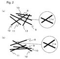
- a reinforcing fiber monofilament 8 intersects reinforcing fiber monofilaments 12 and 13 when the reinforcing fiber monofilament 8 is defined as a reference.
- the two-dimensional intersection angle between the reinforcing fiber monofilament 8 and the reinforcing fiber monofilament 12 is denoted by reference numeral 14.
- the reinforcing fiber monofilament 8 intersects only the reinforcing fiber monofilament 12 when the reinforcing fiber monofilament 8 is defined as a reference.
- the two-dimensional intersection angle between the reinforcing fiber monofilament 8 and the reinforcing fiber monofilament 12 is denoted by reference numeral 14.
- the condition (III) specified in the present invention is that the tensile elongation of the matrix resin (B) mainly including a polyarylene sulfide is 1.5 to 10%.
- the tensile elongation is in the range of 1.5 to 10%, the tensile strength of the reinforcing fibers (A) themselves can be efficiently utilized due to a balance in elongation between the reinforcing fibers (A) and the matrix resin (B).
- the matrix resin has a low elongation, and therefore the resin is ruptured before the potential of the reinforcing fibers is sufficiently exhibited, so that the tensile strength of the molded article cannot be sufficiently exhibited.
- the tensile elongation of the matrix resin (B) is preferably 2.0% or more, more preferably 2.5% or more.
- the tensile elongation is more than 10%, the polyarylene sulfide as a main component of the matrix resin has a large molecular weight, resulting in poor fluidity during molding.
- the tensile elongation of the matrix resin (B) is preferably 4% or less, more preferably 3% or less.
- the tensile elongation of the matrix resin (B) refers to a breaking point strain which is measured from a Type-I dumbbell test piece using a strain gauge in conformity with ASTM D638.
- the polyarylene sulfide as a main component of the matrix resin (B) is a homopolymer or a copolymer which has a repeating unit of the formula -(Ar-S)- as a main constituent unit and contains preferably 80 mol% or more, more preferably 90 mol% or more, further preferably 95 mol% or more of the repeating unit (hereinafter, the polyarylene sulfide will be sometimes abbreviated as PAS).
- PAS the polyarylene sulfide
- PAS polyarylene sulfide
- Examples of Ar include units represented by the formulae (a) to (k), and units represented by the formula (a) are especially preferable.
- R1 and R2 each represent a substituent selected from hydrogen, an alkyl group having 1 to 12 carbon atoms, an alkoxy group having 1 to 12 carbon atoms, an arylene group having 6 to 24 carbon atoms, and a halogen group, and R1 and R2 may be the same, or different.
- the polyarylene sulfide may contain a small amount of branched units or crosslinked units represented by the following formulae (I) to (n).
- the copolymerization amount of branched units or crosslinked units is preferably in the range of 0 to 1 mol% based on 1 mol of the - (Ar-S) - unit.
- the PAS in the present invention may be any one of a random copolymer and a block copolymer including the above-mentioned repeating unit, and a mixture thereof.
- Typical examples of the PAS in the present invention include polyphenylene sulfides (formulae (a), (b) and (f) to (k)), polyphenylene sulfide sulfones (formula (d)), polyphenylene sulfide ketones (formula (c)), polyphenylene sulfide ethers (formula (e)), random copolymers and block copolymers thereof, and mixtures thereof.
- PAS particularly preferred PAS
- polyphenylene sulfides containing 80 mol% or more, particularly 90 mol% or more of a p-phenylene sulfide unit: as a main constituent unit of the polymer hereinafter, the polyphenylene sulfide will be sometimes abbreviated as a PPS).
- the PAS in the present invention has a mass average molecular weight of preferably 10,000 to 80,000, more preferably 10,000 to 60,000, further preferably 10,000 to 40,000.
- a PAS having a smaller mass average molecular weight has a lower melt viscosity, is superior in moldability into a complicated shape, and can more reliably inhibit the fiber length of the reinforcing fibers (A) from decreasing due to damage during molding.
- the mass average molecular weight of the PAS can be measured using generally known GPC (gel permeation chromatography) such as size exclusion chromatography (SEC).
- GPC gel permeation chromatography
- SEC size exclusion chromatography
- the mass average molecular weight of the PAS can be determined by calculating the mass average molecular weight in terms of polystyrene with 1-chloronaphthalene used as an eluent and the column temperature set to 210°C.
- the condition (IV) specified in the present invention is that the interfacial shear strength between the reinforcing fibers (A) and the matrix resin (B) mainly including a PAS is 20 MPa or more. Bondability between the reinforcing fibers (A) and the matrix resin (B) is represented by the interfacial shear strength (hereinafter, the interfacial shear strength will be sometimes abbreviated as IFSS), and when the bondability is high, the IFSS shows a high value. For improving the tensile strength of the molded article, it is important that the IFSS is 20 MPa or more.
- the IFSS When the IFSS is less than 20 MPa, a load applied to the molded article is transmitted from the matrix resin (B) to the reinforcing fibers (A), and before the reinforcing fibers (A) are sufficiently burdened with the load, the interface between the reinforcing fibers (A) and the matrix resin (B) is ruptured, so that the tensile strength of the molded article cannot be sufficiently exhibited.
- the IFSS is more preferably 25 MPa or more, especially preferably 35 MPa or more.
- the IFSS varies depending on the characteristics of the matrix resin (B) to be used, but as long as the IFSS is not less than 50 MPa, a molded article having a sufficiently increased tensile strength as intended by the present invention can be provided.
- the IFSS is in such a range, advantages resulting from improvement of the tensile strength of the reinforcing fibers (A) and the tensile elongation of the matrix resin (B) can be effectively exhibited.
- Non-Patent Document 1 One reinforcing fiber monofilament having a length of 20 cm is taken out from a reinforcing fiber bundle. Subsequently, two 150 ⁇ m-thick matrix resin films having a size of 20 ⁇ 20 cm square are prepared, the reinforcing fiber monofilament taken out from the reinforcing fiber bundle is linearly disposed on one of the matrix resin films.
- the other matrix resin film is superimposed thereon so as to sandwich the reinforcing fiber monofilament between the matrix resin films, and pressing is performed at a pressure of 0.5 MPa at 320°C for 3 minutes to prepare a sample with a reinforcing fiber monofilament embedded in a matrix resin.
- the obtained sample is cut to obtain a sample piece having a thickness of 0.2 mm, a width of 10 mm and a length of 70 mm with a reinforcing fiber monofilament buried at the center.
- Ten test pieces are prepared in the same manner as described above.
- the test piece is subjected to a tension test at a strain rate of 0.5 mm/min with the test length set to 25 mm.
- the lengths of all the fragments of the reinforcing fiber monofilament at the time when the reinforcing fiber monofilament is no longer broken is measured with a transmission microscope, and the measured lengths are averaged to determine an average breakage fiber length L.
- ⁇ f is determined by the following method on the premise that the tensile strength distribution of the reinforcing fiber monofilament follows the Weibull distribution. Specifically, only the reinforcing fiber monofilament is subjected to a tension test without embedding the reinforcing fiber monofilament in the matrix resin, a relational expression between the sample length and the average tensile strength is derived by a least square method from the average tensile strength obtained with each of the sample lengths of 5 mm, 25 mm and 50 mm, and the average tensile strength at a sample length Lc is calculated.
- the matrix resin (B) contains 0.1 to 10% by mass of a compound having, in one molecule, three or more functional groups of at least one type selected from a carboxyl group, an amino group, a hydroxyl group and an epoxy group for improving interfacial bondability between the reinforcing fibers (A) and the matrix resin (B) to improve the tensile strength of the molded article.
- the content of the compound is more preferably 0.2 to 8% by mass, especially preferably 0.6 to 5% by mass.
- Two or more of types of the functional groups may exist in one molecule, or two or more compounds having three or more functional groups of one type in one molecule may be used in combination.
- the compound having, in one molecule, three or more functional groups as described above is preferably an aliphatic compound.
- the aliphatic compound here is an acyclic linear saturated hydrocarbon, a branched saturated hydrocarbon, a cyclic saturated hydrocarbon, an acyclic linear unsaturated hydrocarbon, a branched unsaturated hydrocarbon, or a compound of chain structure in which a carbon atom (CH 3 , CH 2 , CH or C) in the hydrocarbon is replaced by an oxygen atom (O), a nitrogen atom (NH or N) or a carbonyl atom group (CO).
- the aliphatic compound does not have an aromatic backbone such as a benzene ring.
- the compound having, in one molecule, three or more specific functional groups as described above is an aliphatic compound because affinity between the reinforcing fibers (A) and the matrix resin (B) is improved, so that a molded article excellent in dynamic characteristics is obtained.
- the compound having, in one molecule, three or more specific functional groups as described above include polyfunctional epoxy resins, acrylic acid-based polymers, polyhydric alcohols and polyethyleneimines, and in particular, polyfunctional epoxy resins having high reactivity with both the surface functional groups of the reinforcing fibers (A) and the matrix resin (B) are preferably used.
- polyfunctional epoxy resin examples include tri-or-more functional aliphatic epoxy resins and phenol novolac-type epoxy resins. Among them, tri-or-more functional aliphatic epoxy resins are preferable because they have a plurality of reaction points and hence high reactivity, so that affinity between the reinforcing fibers (A) and the matrix resin (B) are improved.
- the tri-or-more functional aliphatic epoxy resin means an aliphatic epoxy resin having three or more epoxy groups in one molecule.
- tri-or-more functional aliphatic epoxy resin examples include polyglycidyl ethers of aliphatic polyhydric alcohols such as glycerol triglycidyl ether, diglycerol polyglycidyl ether, polyglycerol polyglycidyl ether, sorbitol polyglycidyl ether, arabitol polyglycidyl ether, trimethylolpropane triglycidyl ether and pentaerythritol polyglycidyl ether.
- polyglycidyl ethers of aliphatic polyhydric alcohols such as glycerol triglycidyl ether, diglycerol polyglycidyl ether, polyglycerol polyglycidyl ether, sorbitol polyglycidyl ether, arabitol polyglycidyl ether, trimethylolpropane triglycidyl ether and pentaerythr
- glycerol triglycidyl ether diglycerol polyglycidyl ether and polyglycerol polyglycidyl ether are preferably used in the present invention because they contain a large number of epoxy groups having high reactivity in one molecule, have high water solubility, and are easily applied to the reinforcing fibers (A).
- the acrylic acid-based polymer is a generic name of polymers which are polymers of acrylic acid, methacrylic acid and maleic acid, and contain three or more carboxyl groups in one molecule.
- Specific examples of the acrylic acid-based polymer include polyacrylic acids, copolymers of acrylic acid and methacrylic acid, copolymers of acrylic acid and maleic acid, and mixtures of two or more thereof.
- the acrylic acid-based polymer may be one with the carboxyl group partially neutralized with an alkali (i.e. formed into a carboxylate) as long as the number of functional groups as described above is 3 or more in one molecule.
- alkali examples include alkali metal hydroxides such as sodium hydroxide, lithium hydroxide and potassium hydroxide, and ammonium hydroxide.
- alkali metal hydroxides such as sodium hydroxide, lithium hydroxide and potassium hydroxide, and ammonium hydroxide.
- acrylic acid-based polymer a polyacrylic acid containing a larger number of carboxyl groups in one molecule is preferably used.
- polyhydric alcohol examples include polyvinyl alcohol, glycerol, diglycerol, polyglycerol, sorbitol, arabitol, trimethylolpropane and pentaerythritol.
- polyhydric alcohol a polyvinyl alcohol containing a larger number of hydroxyl groups in one molecule can be preferably used.
- the polyethyleneimine is a polyamine which is obtained by ring-opening polymerization of ethylene imine, and has a branched structure formed by primary, secondary and tertiary amino groups.
- a polyethyleneimine containing a larger number of amino groups in one molecule is preferably used.
- the compound having, in one molecule, three or more specific functional groups as described above is preferably one in which the value obtained by dividing the mass average molecular weight of the compound by the number of the above-described functional groups (the total number of carboxyl groups, amino groups, hydroxyl groups and epoxy groups) in one molecule is 40 to 150. It is preferable that the above-mentioned value is in such a range because the density of reaction points with the surface functional groups of the reinforcing fibers (A) and the functional groups of the matrix resin (B) can be made more uniform, and affinity between the reinforcing fibers (A) and the matrix resin (B) can be improved to further increase the tensile strength of the resulting molded article.
- the matrix resin (B) further contains 0.1 to 10% by mass of a compound having, in one molecule, two or more structures of at least one type selected from a carbodiimide structure, a urea structure and a urethane structure for further improving affinity between the reinforcing fibers (A) and the matrix resin (B), so that the tensile characteristics of the resulting molded article is improved.
- the blending amount is preferably 0.3 to 8% by mass, and especially preferably in the range of 0.5 to 5% by mass in view of generation of a decomposed gas at the time of kneading the compound with the matrix resin.
- Examples of the compound having a carbodiimide structure i.e. the carbodiimide compound, include polycarbodiimides, which include aliphatic polycarbodiimides and aromatic polycarbodiimides, and aliphatic polycarbodiimides are preferably used from the viewpoint of affinity and reactivity with the reinforcing fibers (A) and the matrix resin (B).
- the compound having a urea structure one obtained by reacting a diisocyanate with a diamine including a compound containing a plurality of amino groups (e.g. hydrazine, dihydrazide or the like) can be used.
- the polyurea can be synthesized by reacting an isocyanate with water to form unstable carbamic acid.
- the carbamic acid is decomposed to generate carbon dioxide and form amino groups that immediately react with an isocyanate to form a urea bridge.
- the polyurea is obtained by treating a compound having a carbodiimide structure with water to react the carbodiimide into urea.
- the compound having a urethane structure one obtained by reacting bischloroformate with diamine can be used.
- the polyurethane can be synthesized by reacting a diisocyanate with a diol such as a macroglycol, a polyol, or a combination of a macroglycol and a single-chain glycol extending agent.
- polycarbodimides are preferably used from the viewpoint of interfacial bonding to the reinforcing fibers (A).
- the PAS as a main component of the matrix resin (B) when the PAS as a main component of the matrix resin (B) has a smaller mass average molecular weight, it has a lower melt viscosity, and is superior in molding processability in production of a molded article as described above.
- the dynamic characteristics, such as the tensile strength and the elongation, of the resulting molded article tend to be improved. This may be because functional groups of the PAS chemically react with functional groups existing on the surfaces of reinforcing fibers.
- the mass average molecular weight of the PAS as a main component of the matrix resin (B) is in the range of 10,000 to 40,000 in the molded article according to the present invention because both the dynamic characteristics of the resulting molded article and the molding processability can be achieved at a high level.
- the matrix resin (B) is a carbodiimide-modified polyarylene sulfide obtained from a polyarylene sulfide and a carbodiimide compound
- the matrix resin (B) having a high tensile elongation is obtained even when the polyarylene sulfide has a small mass average molecular weight. Since the mass average molecular weight of the polyarylene sulfide is small, it is easy to combine the reinforcing fibers (A) and the matrix resin (B), and the number average fiber length of the reinforcing fibers (A) in the resulting molded article is increased, so that a molded article having a high strength is obtained.
- the matrix resin (B) is a carbodiimide-modified polyarylene sulfide obtained from a polyarylene sulfide and a carbodiimide compound in the molded article according to the present invention
- the mass average molecular weight of the polyarylene sulfide is in the range of 10,000 to 40,000 because both the tensile strength and productivity of the resulting molded article and the molding processability can be achieved at a high level.
- the content of volatile components when the PAS is heated and melted at 320°C for 120 minutes is preferably 0.8% by mass or less from the viewpoint of a work environment during molding, and for reducing the generation amount of voids in the molded article, and preventing contamination due to generation of gas on the metal side when the molded article is used integrally with a metal member of aluminum etc., or used in combination with a metal member having an elevated temperature at a use site.
- the content of volatile components is further preferably 0.5% by mass or less.
- the generation amount of volatile components can be measured from a mass decrease ratio with respect to the mass of a sample before measurement when the PAS is heated at a temperature elevation rate of 20°C/minute at a nitrogen flow rate of 30 mL/minute, and then held at 320°C for 120 minutes using Differential Thermal Balance (TG-DTA) Standard Model CN8078B1 manufactured by Rigaku Corporation.
- TG-DTA Differential Thermal Balance
- the average of fiber lengths observed from the breakage cross-section after tension breakage of the molded article is preferably 0.2 mm or less because a sufficient effect of improving the tensile strength of the molded article is obtained.
- a state in which the reinforcing fibers (A) falls off the matrix resin (B) is observed when a breakage surface after a tension test is observed. This may be because surface bondability between the matrix resin (B) and the reinforcing fibers (A) is not sufficient.
- the length of the reinforcing fiber (A) that falls off the matrix resin and the tensile strength is usually called a critical fiber length. It suffices that the average of fiber lengths is 0.2 mm or less from the viewpoint of a critical fiber length, and the average of fiber lengths is more preferably 0.15 mm or less, especially preferably 0.1 mm or less.
- FIG. 1 A test piece is disposed in such a manner that the breakage surface after a tension test is level with a sample stand, and fiber lengths at the surface area are observed using a scanning electron microscope.
- Contact ends (7 in Fig. 1(a) ) between a reinforcing fiber monofilament (3 in Fig. 1(a) ) protruding from the breakage surface and the matrix resin (B) are connected by a straight line, a perpendicular line is drawn from the center of the straight line to the tip of the protruding reinforcing fiber monofilament (4 in Fig.
- the average of fiber lengths can be determined by measuring the fiber length for up to 400 fibers in total, and dividing the total of the measured lengths by the number of the fibers. If the number of measurable reinforcing fibers in one test piece is less than 400, or 400 reinforcing fibers exist, but it is difficult to measure 400 fibers, the number of samples may be increased to measure 400 fibers in total.
- the molded article according to the present invention is in a state in which the matrix resin (B) is deposited on the surfaces of the reinforcing fibers (A) observed from the breakage cross-section after tension breakage of the molded article.
- the state can be evaluated by the ratio of the number of reinforcing fibers (A) with the lumped matrix resin (B) deposited on at least a part of the surface to the number of reinforcing fibers (A) observed from the breakage cross-section.
- the ratio of reinforcing fibers (A) with the matrix resin (B) deposited on the surface is preferably 10% or more, further preferably 40% or more, more preferably 70% or more. This ratio is preferably as high as possible because the bonding strength between the reinforcing fibers (A) and the matrix resin (B) becomes higher, so that the effect by improvement of the tensile strength of the matrix resin (B) can be effectively exhibited.
- the ratio of reinforcing fibers (A) with the matrix resin (B) deposited on the surface is measured in the following manner: test piece is disposed in such a manner that the breakage surface after a tension test is level with a sample stand, total 400 reinforcing fiber (A) monofilaments protruding from the breakage surface are observed using a scanning electron microscope, the number of reinforcing fiber (A) monofilaments with the lumped matrix resin (B) deposited on at least a part of the surface is measured, and the ratio of reinforcing fibers (A) with the matrix resin (B) deposited on the surface is determined using the following equation.
- Q w / M ⁇ 100 unit : %
- the method for producing the molded article according to the present invention is preferably a method in which a molding material is provided beforehand, and molded and processed to produce a molded article.
- the first preferred method for producing a molding material is, for example, a method in which the reinforcing fibers (A) and the matrix resin (B) are simultaneously melted and kneaded, then cooled in a strand bath, and cut to be pelletized
- the second preferred method for producing a molding material is a method in which a base material formed of the reinforcing fibers (A) is impregnated and/or covered with the melted matrix resin (B), then cooled, and cut to a pellet shape.
- the third component is added, mention is made of, for example, a method in which the third component is added to the reinforcing fibers (A) beforehand (sizing method), and a method in which the third component is dry-blended with the matrix resin (B).
- the melting and kneading method is not particularly limited, and a known heating, melting and mixing apparatus can be used.
- a single-screw extruder, a twin-screw extruder, a twin-screw extruder including a combination of a single-screw extruder and a twin-screw extruder, a kneader extruder or the like can be used.
- a twin-screw extruder is preferably used from the viewpoint of mixing power, and a twin-screw extruder having two or more kneading zones is more preferably used.
- the kneading zone is a region which includes one or more kneading disks installed in a screw of a twin-screw extruder and which has a higher effect of dispersing the reinforcing fibers (A) in the form of monofilaments and a higher effect of decreasing the number average fiber length as compared to other zones. Accordingly, it is preferable to control kneading zones, and the total length of the kneading zones is preferably 1 to 30%, further preferably 1 to 20%, more preferably 1 to 15% of the full length of the screw. Regions other than kneading zones are preferably full-flight zones including one or more full-flights installed in the screw.
- the twin-screw extruder one having a (screw length)/(screw diameter) ratio of 20 to 100 is preferably selected from the view point of productivity.
- the cylinder temperature in melting and kneading is preferably 250 to 400°C, further preferably 280 to 350°C. It is preferable that the cylinder temperature is in such a temperature range because breakage of the reinforcing fibers (A) during melting and kneading is suppressed, so that the length of the reinforcing fibers (A) in the resulting molding material and molded article can be increased.
- the form of the reinforcing fibers (A) at the time of putting the reinforcing fibers (A) in the heating, melting and mixing apparatus may be either a continuous fiber form or a discontinuous fiber form in which the fibers are cut to a specific length.
- the step of cutting the reinforcing fibers (A) can be omitted, and therefore productivity is improved.
- the reinforcing fibers (A) are dispersed in the form of monofilaments in the molding material. It is preferable that the reinforcing fibers (A) are dispersed beforehand because breakage of the reinforcing fibers (A) can be reduced in the process of molding the molding material into a molded article.
- the base material formed of the reinforcing fibers (A) may include reinforcing fiber bundles formed by bunching the continuous reinforcing fibers (A) (hereinafter, referred to simply as a reinforcing fiber bundle), base materials in which continuous reinforcing fibers are unidirectionally oriented (hereinafter, referred to simply as a unidirectionally arranged base material), woven fabrics (cloths), nonwoven fabrics, mats, knitted fabrics, braids, yarns and tows.
- reinforcing fiber bundles are preferably used because they can be continuously taken up at a high speed, leading to excellent productivity.
- the number of monofilaments is preferably 10,000 or more.
- the number of monofilaments is more preferably not less than 10,000 and not more than 100,000, especially preferably not less than 10,000 and not more than 50,000 for securing both economy and impregnability.
- the method for melting the matrix resin (B) may be, for example, a method using the heating, melting and mixing apparatus.
- the base material formed of the reinforcing fibers (A) can be impregnated and/or covered with the matrix resin (B) by feeding the melted matrix resin (B) to an impregnation tank, and bringing the matrix resin (B) into contact with the base material formed of the reinforcing fibers (A).
- the impregnation tank here is a vessel including a mechanism capable of continuously carrying out a step of immersing in the melted matrix resin (B) the base material formed of the reinforcing fibers (A), and taking up the base material.
- the impregnation tank further includes a heating source for storing the matrix resin (B) in a melted state for a predetermined period of time.
- the impregnation tank further includes therein a slit structure in which the spacing of a cavity is inclined, a movable roll or a stationary bar for improving the effect of impregnating the gaps between reinforcing fiber (A) monofilaments with the matrix resin (B).
- the mass average molecular weight of the PAS as a main component of the matrix resin (B) is preferably small because the base material formed of the reinforcing fibers (A) is easily impregnated with the matrix resin (B).
- the mass average molecular weight of the PAS which satisfies such a condition may be, for example, in the range of 10,000 to 40,000.
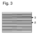
- the reinforcing fibers (A) are arranged almost in parallel to the axial center direction of the molding material, and the length of the reinforcing fiber (A) is substantially the same as the length of the molding material as shown in Fig. 3 .
- symbol 3 denotes a black area
- symbol 2 denotes a white area.
- the phrase "arranged almost in parallel to” as mentioned here refers to a state in which the axis line of the major axis of the reinforcing fiber (A) and the axis line of the major axis of the molding material are directed in the same direction, and the angular deviation between the axis lines is preferably 20° or less, more preferably 10° or less, further preferably 5° or less.
- the phase "substantially the same length” means that for example in a pellet-shaped molding material, the reinforcing fiber (A) is not cut at some midpoint in the pellet, and reinforcing fibers (A) significantly shorter than the full length of the pellet are not substantially included.
- the amount of reinforcing fibers (A) shorter than the full length of the pellet is not particularly specified, but when the content of reinforcing fibers (A) having a length equal to or less than 50% of the full length of the pellet is 30% by mass or less, it is determined that reinforcing fibers (A) significantly shorter than the full length of the pellet are not substantially included. Further, the content of reinforcing fibers (A) having a length equal to or less than 50% of the full length of the pellet is preferably 20% by mass or less.
- the full length of the pellet is a length in the orientation direction of the reinforcing fibers (A) in the pellet. When the reinforcing fibers (A) have a length equivalent to that of the molding material, the fiber length of the reinforcing fibers (A) in the molded article can be increased, so that excellent dynamic characteristics can be obtained.
- the molding material allows the reinforcing fibers (A) to be dispersed in the form of monofilaments in the process of molding the molding material into a molded article, and the mass average molecular weight of the PAS as a main component of the matrix resin (B) is preferably small because breakage of the reinforcing fibers (A) is suppressed.
- the mass average molecular weight of the PAS which satisfies such a condition may be, for example, in the range of 10,000 to 40,000.
- the number average fiber length of the reinforcing fibers (A) included in the molding material in the present invention is preferably 4 to 10 mm.
- the number average fiber length here can be measured by applying to the molding material the method for measuring the number average fiber length in the molded article.
- the second method is more preferable as a method for producing a molding material because a molding material as described above can be obtained with high productivity.
- the molded article according to the present invention is obtained by providing a molding material in the form of a pellet, and molding the molding material from the viewpoint of moldability.
- the molding method using the molding material include injection molding (injection compression molding, gas-assisted injection molding, insert molding and so on).
- injection molding is preferably used from the viewpoint of productivity and moldability into a complicated shape.
- the cylinder temperature in injection molding is preferably 250 to 400°C, further preferably 280 to 350°C.
- the die temperature in injection molding is preferably 40 to 250°C, further preferably 120 to 200°C.
- the molded articles according to the present invention may contain an impact resistance improving agent such as an elastomer or a rubber component, and other fillers and additives as long as the effect of the present invention is not impaired.
- the additives include flame retardants, conductivity imparting agents, nucleating agents, ultraviolet absorbers, antioxidants, vibration controlling agents, antibacterial agents, insect repellents, deodorants, coloration preventing agents, heat stabilizers, mold release agents, antistatic agents, plasticizers, lubricants, colorants, pigments, dyes, foaming agents and antifoaming agents.
- the molded articles according to the present invention are suitable as electronic device housings, and are suitably used in computers, televisions, cameras, audio players and the like.
- the molded articles according to the present invention are suitable in electric and electronic component applications, and are suitably used in connector, LED lamps, sockets, optical pickups, terminal plates, printed boards, speakers, small motors, magnetic heads, power modules, power generators, electric motors, transformers, current transformers, voltage regulators, rectifiers, inverters and the like.
- the molded articles according to the present invention are suitable for automobile components, vehicle related components and so on, and are suitably used in safety belt components, instrument panels, console boxes, pillars, roof rails, fenders, bumpers, door panels, roof panels, hood panels, trunk lids, door mirror stays, spoilers, hood louvers, wheel covers, wheel caps, garnishes, intake manifolds, fuel pumps, engine cooling water joints, wind washer nozzles, wipers, battery peripheral components, wire harness connectors, lamp housings, lamp reflectors, lamp sockets and the like.
- the molded articles according to the present invention are suitable as building materials, and are suitably used in wall, roof and ceiling material related components, window material related components, heat insulator material related components, floor material related components, base isolation vibration damping member related components, lifeline related components and the like in civil engineering and construction products.
- the molded articles according to the present invention are suitable as sports goods, and are suitably used in golf related goods such as golf club shafts and golf balls, sports racket related goods such as tennis rackets and badminton rackets, body protection goods for sports such as masks, helmets, chest protectors, elbow pads and kneepads in American football, baseball, softball and the like, fishing tackle related goods such as fishing rods, reels and fishing lures, winter sports related goods such as skis and snowboards, and the like.
- golf related goods such as golf club shafts and golf balls
- sports racket related goods such as tennis rackets and badminton rackets
- body protection goods for sports such as masks, helmets, chest protectors, elbow pads and kneepads in American football, baseball, softball and the like
- fishing tackle related goods such as fishing rods, reels and fishing lures
- winter sports related goods such as skis and snowboards, and the like.
- the strand tensile strength was determined in accordance with the following procedure in conformity with the resin impregnation strand test method in JIS R7608 (2007) using a reinforcing fiber bundle including reinforcing fibers (A).
- a sample obtained by cutting a part of a molded article, or a molding material was heating-pressed at 300°C to obtain a 30 ⁇ m-thick film.
- the obtained film was observed at a magnification of 25 to 150 depending on the fiber lengths of the reinforcing fibers (A) to be observed with an optical microscope, and fibers dispersed in the film were observed.
- the lengths of the fibers were measured to a unit of 1 ⁇ m, and the number average fiber length (Ln) was determined from the following equation.
- Number average fiber length Ln ⁇ Li / Ntotal
- a molded article molded under the same conditions as those for a molded article subjected to a tension test is embedded in an epoxy resin.
- the surface of the embedded molded article was polished to a depth of 100 ⁇ m from the surface to prepare a test piece for observation.
- the polished surface of the molded article was observed with a microscope to determine the main orientation direction.
- any direction was set to a reference direction D, 400 reinforcing fiber monofilaments were randomly selected, and the angle ⁇ (unit: °) formed by each of the reinforcing fiber monofilaments with respect to the reference direction D was measured.
- angles ⁇ acute angle and obtuse angle
- the angle ⁇ on the acute angle side (-90° ⁇ ⁇ ⁇ 90°) was measured.
- the angle ⁇ was considered as a positive angle when the acute angle was formed in a clockwise direction with respect to the reference direction D
- the angle ⁇ was considered as a negative angle when the acute angle was formed in a counterclockwise direction with respect to the reference direction D.
- the sum of angles ⁇ ( ⁇ ) formed by the 400 measured reinforcing fiber monofilaments with respect to the reference direction D was determined, and divided by 400, i.e. the number of the measured monofilaments, to calculate the average of angles ⁇ .
- the direction along the most intense orientation in the molded article was considered as a direction at the average of angles ⁇ with respect to the reference direction D, and the direction along the most intense orientation was determined as a main orientation direction of reinforcing fibers in the molded article, and defined as 0°.
- a direction orthogonal to the direction 0° determined in this measurement was defined as 90°.
- a tension test in the main orientation direction (0° direction) determined in (3) and a direction (90° direction) orthogonal to the main orientation direction was conducted in conformity with ASTM D638.
- a test piece processed into a Type-I dumbbell test piece was used, and "Instron (registered trademark)" Universal Tester Model (manufactured by Instron, Ltd.) was used as a tester.
- a value obtained in the following manner was used as the tensile strength: a load at a breakage point at which tension breakage of the test piece occurred in the measurement specified in ASTM D638 was divided by the cross-section area of a parallel part of the dumbbell test piece subjected to the test.
- a breakage point strain measured using a strain gauge attached to the parallel part was used.
- a tensile test piece equally scaled down while maintaining the shape with respect to a test piece size conforming to the specification was cut out from a molded article part having a flat plate shape wherever possible, and evaluation was performed.
- a part of a molded article was cut out, the test piece cut out from the molded article was embedded in an epoxy resin, and the surface of the molded article was polished to a depth of 100 ⁇ m from the surface to prepare a test piece for observation.
- the test piece for observation from the molded article was observed with an optical microscope, a reinforcing fiber monofilament (s) serving as a reference was randomly selected, and the two-dimensional intersection angle was measured for all reinforcing fiber monofilaments (t) that was in contact with the reinforcing fiber monofilament (s).
- the two-dimensional contact angle was measured in the acute angle range between 0° and 90°, and the ratio of reinforcing fiber monofilaments having a two-dimensional contact angle of 5° or more was calculated from the total number of reinforcing fiber monofilaments (t) subjected to measurement of the two-dimensional intersection angle. This measurement was repeated 100 times.
- P n / N ⁇ 100 unit : %
- IFSS Interfacial shear strength
- Non-Patent Document 1 One monofilament having a length of 20 cm was taken out from reinforcing fibers (A) used in each of examples and comparative examples. Two resin films used in each of examples and comparative examples were provided, and the monofilament taken out from the reinforcing fibers (A) was linearly disposed on one of the resin films. The other resin film was superimposed thereon so as to sandwich the monofilament between the matrix resin films, and pressing was performed at a pressure of 0.5 MPa at 320°C for 3 minutes to prepare a sample with a monofilament embedded in a resin.
- the obtained sample was cut to obtain a sample piece having a thickness of 0.2 mm, a width of 10 mm and a length of 70 mm with a monofilament buried at the center.
- Ten test pieces were prepared in the same manner as described above.
- the reinforcing fibers (A) and matrix resin (B) used in each of examples and comparative examples were combined to prepare a sample, and the sample was subjected to evaluation.
- the test piece was subjected to a tension test at a strain rate of 0.5 mm/min with the test length set to 25 mm.
- the lengths of all the fragments of the monofilament at the time when the monofilament was no longer broken were measured with a transmission microscope, and the measure lengths are averaged to determine an average breakage fiber length L.
- ⁇ f was determined by the following method on the premise that the tensile strength distribution of the reinforcing fiber (A) would follow the Weibull distribution.
- the tensile strength of each of the monofilaments having sample strengths of 5 mm, 25 mm and 50 mm was determined according to JIS R7606.
- a reinforcing fiber bundle was divided into four equal parts, and 100 monofilaments were sequentially sampled from the four bundles.
- the monofilaments were sampled as equally as possible from the whole bundle.
- the sampled monofilaments were fixed on a perforated paste board using an adhesive.
- the paste board with the monofilaments fixed thereon was attached to a tension tester, and a tension test was conducted at a strain rate of 1 mm/min with a sample number of 100.
- a relational expression between the sample length and the average tensile strength was derived by a least square method from the average tensile strength obtained with each of the sample lengths, and the average tensile strength at a sample length Lc was calculated, and defined as ⁇ f.
- the mass average molecular weight of a PAS was calculated as a mass average molecular weight (Mw) in terms of a polystyrene using gel permeation chromatography (GPC). GPC measurement conditions are shown below.
- a test piece was disposed in such a manner that the breakage surface after a tension test was level with a sample stand, and fiber lengths at the surface area were observed using a scanning electron microscope.
- Contact ends between a reinforcing fiber monofilament protruding from the breakage surface and the matrix resin (B) were connected by a straight line, a perpendicular line was drawn from the center of the straight line to the tip of the protruding reinforcing fiber monofilament, and the length of the perpendicular line was measured to a unit of 1 ⁇ m.
- a measurement was made in the same manner as described above even when the reinforcing fiber monofilament was covered with the matrix resin (B).
- the average of fiber lengths was determined by measuring the fiber length for up to 400 fibers in total, and dividing the total of the measured lengths by the number of the fibers.
- a test piece was disposed in such a manner that the breakage surface after a tension test was level with a sample stand, and reinforcing fiber (A) monofilaments protruding from the breakage surface were observed using a scanning electron microscope. Total 400 reinforcing fiber (A) monofilaments were observed, and the number of reinforcing fiber (A) monofilaments with the lumped matrix resin (B) deposited on at least a part of the surface was measured. The ratio of reinforcing fibers (A) with the lumped matrix resin (B) deposited on at least a part of the surface was determined from the following equation, and evaluated in the following four grades, and samples rated "fair" to "excellent” were determined as passing.
- Q w / M ⁇ 100 unit : %
- CF-1 A copolymer mainly including polyacrylonitrile was subjected to spinning, a firing treatment and a surface oxidation treatment to obtain a continuous carbon fiber strand with a total monofilament number of 12,000.
- the characteristics of the carbon fiber were as shown below.
- GF-1 made of E-glass; a continuous glass fiber strand with a total monofilament number of 1600.
- the characteristics of the glass fiber were as shown below.
- CDI-1 aliphatic polycarbodiimide
- CARBODILITE registered trademark
- HMV-8CA manufactured by Nisshinbo Chemical Inc.
- a reinforcing fiber bundle including reinforcing fibers (A) was continuously taken up, immersed in an aqueous surface treatment agent mother liquor containing 2% by mass of a surface treatment agent, and then heated and dried at 230°C to obtain reinforcing fibers (A) with a surface treatment agent deposited thereon.
- the reinforcing fibers (A) were defined as CF-1, and the reinforcing fibers (A) with a surface treatment agent deposited thereon, which were obtained using SZ-1 as the surface treatment agent, were defined as CF-3.
- the deposition amount of SZ-1 after drying was 1 part by mass based on 100 parts by mass of CF-1.
- reinforcing fibers (A) with a surface treatment agent deposited thereon were defined as CF-4.
- the deposition amount of SZ-2 after drying was 1 part by mass based on 100 parts by mass of CF-1.
- reinforcing fibers (A) with a surface treatment agent deposited thereon were defined as CF-5.
- the deposition amount of SZ-3 after drying was 1 part by mass based on 100 parts by mass of CF-1.
- CDI-1 was immersed in hot water at 80°C for 5 days to obtain a compound in which carbodiimide groups were transformed to urea groups, and this compound was defined as Urea-1. Transformation of carbodiimide groups to urea groups was confirmed by disappearance of the absorption peak (2119 cm -1 ) of the carbodiimide group in IR spectrum measurement.
- a molding material was prepared according to the following procedure using CF-1 as the reinforcing fibers (A) and PPS-2 as the matrix resin (B), and the molding material was then injection-molded to obtain a molded article.
- CF-1 was cut to a length of 6 mm to prepare chopped strands.
- PPS-2 was main-fed, and the chopped strands were side-fed to melt and knead the components.
- the melting and kneading was performed at a cylinder temperature of 290°C, a screw rotation number of 150 rpm and a discharge rate of 10 kg/hour.
- the discharged product was taken out, and simultaneously cooled by a water cooling bath to form a gut, and the gut was cut to a length of 5 mm to form a pellet.
- the blending amount was adjusted so that the content of CF-1 was 20% by mass, and the content of PPS-2 was 80% by mass.
- the pellet was injection-molded to prepare a molded article.
- the injection molding was performed at a cylinder temperature of 320°C and a die temperature of 150°C.
- Test pieces were provided from the obtained molded article, annealed at 150°C for 2 hours, then air-cooled, and subjected to a test. Evaluation results were described in Table 1.
- a molding material was prepared according to the following procedure using CF-1 as the reinforcing fibers (A) and PPS-3 and Epoxy-1 as the matrix resin (B), and the molding material was then injection-molded to obtain a molded article.
- CF-1 was cut to a length of 6 mm to prepare chopped strands.
- a mixture including PPS-3 and Epoxy-1 with 5% by mass of Epoxy-1 dry-blended with 95% by mass of PPS-3 was main-fed as a raw material of the matrix resin (B), and the chopped strands were side-fed to melt and knead the components.
- the melting and kneading was performed at a cylinder temperature of 290°C, a screw rotation number of 150 rpm and a discharge rate of 10 kg/hour.
- the discharged product was taken out, and simultaneously cooled by a water cooling bath to form a gut, and the gut was cut to a length of 5 mm to form a pellet.
- the blending amount was adjusted so that the content of CF-1 was 30% by mass, and the content of the matrix resin (B) including PPS-3 and Epoxy-1 was 70% by mass.
- the pellet was injection-molded to prepare a molded article.
- the injection molding was performed at a cylinder temperature of 320°C and a die temperature of 150°C.
- Test pieces were provided from the obtained molded article, annealed at 150°C for 2 hours, then air-cooled, and subjected to a test. Evaluation results were described in Table 1.
- the melting and kneading was performed at a cylinder temperature of 290°C, a screw rotation number of 150 rpm and a discharge rate of 10 kg/hour.
- the discharged product was taken out, and simultaneously cooled by a water cooling bath to form a gut, and the gut was cut to a length of 5 mm to obtain a resin pellet including the matrix rein (B).
- the resin pellet was injection-molded to prepare test pieces for tension evaluation.
- the injection molding was performed at a cylinder temperature of 320°C and a die temperature of 150°C.
- the obtained test pieces were annealed at 150°C for 2 hours, then air-cooled, and subjected to a tension test.
- the tensile elongation of the matrix resin (B) thus obtained was described in Table 1.
- Example 6 Except that the component dry-blended with PPS-3 as the matrix resin (B) was changed from Epoxy-1 to CDI-1, the same procedure as in Example 6 was carried out to prepare test pieces, and the test pieces were subjected to a test. Evaluation results were described in Table 1.
- Example 11 (Material) Reinforcing fibers
- A Type % by mass CF - 1 20 CF - 1 30 CF - 1 40 CF - 1 30 CF - 1 30 CF - 1 30 CF - 1 30 GF - 1 30 CF - 1 30 CF - 1 20 Strand strength GPa 4.9 4.9 4.9 4.9 4.9 4.9 4.9 3.4 4.9 4.9
- Example 2 Except that the blending amount of CF-1 as the reinforcing fibers (A) was changed from 20% by mass to 30% by mass, the matrix resin (B) was changed from PPS-2 to PPS-1, and the blending amount thereof was changed from 80% by mass to 70% by mass, the same procedure as in Example 1 was carried out to prepare test pieces, and the test pieces were subjected to a test. Evaluation results were described in Table 2.
- Example 2 Except that the blending amount of CF-1 used as the reinforcing fibers (A) was changed from 20% by mass to 30% by mass, the matrix resin (B) was changed from PPS-2 to PPS-5, and the blending amount thereof was changed from 80% by mass to 70% by mass, the same procedure as in Example 1 was carried out to prepare test pieces, and the test pieces were subjected to a test. Evaluation results were described in Table 2.
- Example 1 to 11 where the strand strength of the reinforcing fibers (A) was secured, the elongation of the matrix rein (B) was selected, the IFSS between the reinforcing fibers (A) and the matrix resin (B) was sufficient, and the number average fiber length of the fibers in the molded article fell within a specific range, the molded article exhibited a high tensile strength of 240 MPa or more in the main orientation direction.
- Examples 6 to 10 where further a compound having a specific functional group, or a compound having a specific structure was mixed in the matrix resin (B), the molded article was superior in tensile strength as compared to Examples 1 to 5.
- the reinforcing fibers had an insufficient strand strength, and the IFSS between the reinforcing fibers (A) and the matrix resin (B) was low, so that the resulting molded article was poor in tensile strength.
- the matrix resin (B) had a large mass average molecular weight, and the reinforcing fibers (A) in the molded article had a small number average fiber length. Further, the IFSS between the reinforcing fibers (A) and the matrix resin (B) was low, so that the resulting molded article was poor in tensile strength.
- the reinforcing fibers (A) in the molded article had a number average fiber length of less than 0.4 mm, and therefore although the IFSS between the reinforcing fibers (A) and the matrix resin (B) was 20 or more, the resulting molded article was poor in tensile strength.
- a molding material was prepared according to the following procedure using CF-1 as the reinforcing fibers (A) and PPS-6 and CDI-1 as the matrix resin (B), and the molding material was then injection-molded to obtain a molded article.
- the melting and kneading was performed at a cylinder temperature of 290°C, a screw rotation number of 150 rpm and a discharge rate of 10 kg/hour.
- the discharged product was taken out, and simultaneously cooled by a water cooling bath to form a gut, and the gut was cut to a length of 5 mm to obtain a resin pellet including the matrix rein (B).
- the resin pellet was injection-molded to prepare test pieces for tension evaluation.
- the injection molding was performed at a cylinder temperature of 320°C and a die temperature of 150°C.
- the obtained test pieces were annealed at 150°C for 2 hours, then air-cooled, and subjected to a tension test.
- the tensile elongation of the matrix resin (B) thus obtained was described in Table 3.
- the resin pellet was melted and kneaded in a single-screw extruder at 320°C to form the molten matrix resin (B), and the molten matrix resin (B) was supplied to an impregnation tank mounted at the head of the extruder. Further, CF-1 was continuously taken up as a reinforcing fiber bundle including the reinforcing fibers (A), and caused to pass through the inside of the impregnation tank, thereby obtaining an impregnated strand with a reinforcing fiber bundle impregnated with a fixed amount of the matrix resin (B) per unit length thereof.
- the impregnated strand was cooled by a water cooling bath to form a gut, and the gut was cut to a length of 7 mm to form a reinforcing fiber-containing pellet.
- the blending amount was adjusted so that the content of the reinforcing fibers (A) was 20% by mass, and the content of the matrix resin (B) was 80% by mass.
- the number average fiber length of the molding material was measured from the thus-obtained reinforcing fiber-containing pellet. The number average fiber length of the molding material was described in Table 3.
- the reinforcing fiber-containing pellet was injection-molded to prepare a molded article.
- the injection molding was performed at a cylinder temperature of 320°C and a die temperature of 150°C.
- Test pieces were provided from the obtained molded article, annealed at 150°C for 2 hours, then air-cooled, and subjected to a test. Evaluation results were described in Table 3.
- Example 12 Except that the compound used in dry-blending as the matrix resin (B) was changed from CDI-1 to Epoxy-1, the same procedure as in Example 12 was carried out to prepare a molding material, and test pieces were provided from a molded article produced using the molding material, and were subjected to various kinds of tests. Evaluation results were described in Table 3.
- Example 12 Except that the compound used in dry-blending as the matrix resin (B) was omitted, and only PPS-6 was used as the matrix resin (B), the same procedure as in Example 12 was carried out to prepare a molding material, and test pieces were provided from a molded article produced using the molding material, and were subjected to various kinds of tests. Evaluation results were described in Table 3.
- Example 12 Except that the PAS used in dry-blending as the matrix resin (B) was changed from PPS-6 to PPS-7, the same procedure as in Example 12 was carried out to prepare a molding material, and test pieces were provided from a molded article produced using the molding material, and were subjected to various kinds of tests. Evaluation results were described in Table 3.
- Example 13 Except that the compound used in dry-blending as the matrix resin (B) was changed from CDI-1 to Epoxy-1, the same procedure as in Example 13 was carried out to prepare a molding material, and test pieces were provided from a molded article produced using the molding material, and were subjected to various kinds of tests. Evaluation results were described in Table 3.
- Example 13 Except that the compound used in dry-blending as the matrix resin (B) was omitted, and only PPS-7 was used as the matrix resin (B), the same procedure as in Example 13 was carried out to prepare a molding material, and test pieces were provided from a molded article produced using the molding material, and were subjected to various kinds of tests. Evaluation results were described in Table 3.
- Example 12 Except that the PAS used in dry-blending as the matrix resin (B) was changed from PPS-6 to PPS-4, the same procedure as in Example 12 was carried out to prepare a molding material, and test pieces were provided from a molded article produced using the molding material, and were subjected to various kinds of tests. Evaluation results were described in Table 3.
- Example 14 Except that the compound used in dry-blending as the matrix resin (B) was changed from CDI-1 to Epoxy-1, the same procedure as in Example 14 was carried out to prepare a molding material, and test pieces were provided from a molded article produced using the molding material, and were subjected to various kinds of tests. Evaluation results were described in Table 3.
- Example 14 Except that the compound used in dry-blending as the matrix resin (B) was omitted, and only PPS-4 was used as the matrix resin (B), the same procedure as in Example 14 was carried out to prepare a molding material, and test pieces were provided from a molded article produced using the molding material, and were subjected to various kinds of tests. Evaluation results were described in Table 3.
- Example 12 Except that the PAS used in dry-blending as the matrix resin (B) was changed from PPS-6 to PPS-5, the same procedure as in Example 12 was carried out to prepare a molding material, and test pieces were provided from a molded article produced using the molding material, and were subjected to various kinds of tests. Evaluation results were described in Table 3.
- Comparison between the molded articles described in Examples 12 to 14 and the molded article described in Comparative Example 12 shows that when the PAS used in the matrix resin (B) has a smaller mass average molecular weight, the number average fiber length of the fibers in the resulting molded article increases, so that a molded article excellent in tensile strength is obtained.
- Example 12 Except that the blending amount of CF-1 used as the reinforcing fibers (A) was changed from 20% by mass to 30% by mass, and the blending amount of the matrix resin (B) was changed from 80% by mass to 70% by mass, the same procedure as in Example 12 was carried out to prepare a molding material, and test pieces were provided from a molded article produced using the molding material, and were subjected to various kinds of tests. Evaluation results were described in Table 4.
- Example 16 Except that the compound used in dry-blending as the matrix resin (B) was omitted, and only PPS-6 was used as the matrix resin (B), the same procedure as in Example 16 was carried out to prepare a molding material, and test pieces were provided from a molded article produced using the molding material, and were subjected to various kinds of tests. Evaluation results were described in Table 4.
- Example 12 Except that the blending amount of CF-1 used as the reinforcing fibers (A) was changed from 20% by mass to 50% by mass, and the blending amount of the matrix resin (B) was changed from 80% by mass to 50% by mass, the same procedure as in Example 12 was carried out to prepare a molding material, and test pieces were provided from a molded article produced using the molding material, and were subjected to various kinds of tests. Evaluation results were described in Table 4.
- Example 12 Except that the reinforcing fibers (A) were changed from CF-1 to CF-3, the same procedure as in Example 12 was carried out to prepare a molding material, and test pieces were provided from a molded article produced using the molding material, and were subjected to various kinds of tests. Evaluation results were described in Table 4.
- Example 12 Except that the reinforcing fibers (A) were changed from CF-1 to CF-4, the same procedure as in Example 12 was carried out to prepare a molding material, and test pieces were provided from a molded article produced using the molding material, and were subjected to various kinds of tests. Evaluation results were described in Table 4.
- Example 12 Except that the reinforcing fibers (A) were changed from CF-1 to CF-5, the same procedure as in Example 12 was carried out to prepare a molding material, and test pieces were provided from a molded article produced using the molding material, and were subjected to various kinds of tests. Evaluation results were described in Table 4.
- Example 16 Except that the reinforcing fibers (A) were changed from CF-1 to GF-1, the same procedure as in Example 16 was carried out to prepare a molding material, and test pieces were provided from a molded article produced using the molding material, and were subjected to various kinds of tests. Evaluation results were described in Table 4.
- Example 16 Comparative Example 15 Comparative Example 16 Comparative Example 17
- Example 18 Example 19
- Example 20 (Material) Reinforcing fibers (A) Type % by mass CF - 1 30 CF - 1 30 CF - 1 50 CF - 1 50 CF - 3 20 CF - 4 20 CF - 5 20 GF-1 30 Strand strength GPa 4.9 4.9 4.9 4.9 4.9 4.9 3.4
- Example 16 shows that when the strand strength of the reinforcing fibers (A), and the IFSS decrease, the strength of the resulting molded article considerably decreases.
- the molded article according to the present invention exhibits an excellent tensile strength.
- the molded article according to the present invention has an outstandingly high tensile strength, and therefore can be used in a wide range of applications such as automobile interiors and exteriors, electric and electronic device housings, reinforcing materials in the field of civil engineering and construction, and sports goods.
- the molding material according to the present invention can be suitably used for producing such a molded article with high productivity.
Landscapes
- Chemical & Material Sciences (AREA)
- Engineering & Computer Science (AREA)
- Polymers & Plastics (AREA)
- Health & Medical Sciences (AREA)
- Chemical Kinetics & Catalysis (AREA)
- Medicinal Chemistry (AREA)
- Organic Chemistry (AREA)
- Mechanical Engineering (AREA)
- Textile Engineering (AREA)
- Composite Materials (AREA)
- Manufacturing & Machinery (AREA)
- Reinforced Plastic Materials (AREA)
- Compositions Of Macromolecular Compounds (AREA)
- Injection Moulding Of Plastics Or The Like (AREA)
Abstract
(I) The strand tensile strength of the reinforcing fibers (A) is 1.5 to 5.5 GPa.
(II) The number average fiber length of the reinforcing fibers (A) is 0.4 to 10 mm.
(III) The tensile elongation of the matrix resin (B) is 1.5 to 10%.
(IV) The interfacial shear strength between the reinforcing fibers (A) and the matrix resin (B) is 20 MPa or more.
Description
- The present invention relates to a molded article including a polyarylene sulfide and reinforcing fibers, and more specifically to a molded article which includes a polyarylene sulfide having high dynamic characteristics, particularly a high tensile elongation, and reinforcing fibers and which is suitably produced by injection molding, and a molding material for producing the molded article.
- Molded articles produced using a fiber-reinforced resin composition including a thermoplastic resin and reinforcing fibers are easily molded and processed by virtue of the characteristics of the thermoplastic resin, do not require a load in storage unlike thermosetting resins, and are excellent in recyclability. As these molded articles, those in a variety of forms are known such as thermoplastic prepregs in which reinforcing fibers are arranged in the form of a sheet, and pellets in which reinforcing fibers are randomly dispersed. Molded articles including reinforcing fibers and a thermoplastic resin are excellent in balance between lightness and dynamic characteristics, and are therefore widely used as structural members of aircrafts, automobiles, watercrafts and the like, electronic equipment housings, sports goods, and industrial materials such as building materials.
- Among thermoplastic resins, a polyarylene sulfide is particularly excellent in heat resistance and chemical resistance, so that a molded article produced using the resin can be expected to be applied as an alternative to a metal material. However, when a molded article produced using a polyarylene sulfide is used as an alternative to a metal material, further improvement of the dynamic characteristics, particularly the tensile strength, of the molded article is desired. This is because since the tensile elongation of a general polyarylene sulfide is lower than the tensile elongation of reinforcing fibers, and interfacial bondability between the polyarylene sulfide and reinforcing fibers is low, the reinforcing effect of reinforcing fibers cannot be sufficiently utilized in the molded article.
- General means for improving the tensile strength and elongation of a molded article is enhancement of the elongation of a polyarylene sulfide. However, the tensile elongation of a polyarylene sulfide correlates to its molecular weight, and hence its melt viscosity, and when the tensile elongation of the polyarylene sulfide is improved, the melt viscosity increases, so that moldability in production of a molded article may be considerably impaired. It is well known that it becomes harder to combine a polyarylene sulfide with reinforcing fibers as the melt viscosity of the polyarylene sulfide increases. In this case, it is necessary to make the process temperature higher, and therefore a polyarylene sulfide is not suitable for easily producing a molded article and a molding material with high productivity. For these reasons, it is an important technical challenge to secure both the tensile strength and molding processability in a molded article produced using a polyarylene sulfide.
- In view of the above-mentioned situations, techniques have been disclosed in which the bending characteristic of a molded article is improved by a molding material obtained by sizing to carbon fibers a compound mainly including an epoxy resin and containing a specific catalyst in a molding material including a polyarylene sulfide and carbon fibers as an attempt to improve dynamic characteristics. In these techniques, attempts are made using various forms of reinforcing fibers (
Patent Document 1,Patent Document 2 and Patent Document 3) . However, in these patent documents, a certain improvement in dynamic characteristics is achieved owing the techniques disclosed in the documents, but for dynamic characteristics, only the bending characteristic is considered, and in addition, it is not conceived that the elongation of a polyarylene sulfide and the state of dispersion of reinforcing fibers in a molded article considerably influence tensile characteristics useful as design parameters for a product. It is predicted that further improvement of the strength is required in application development which will increasingly progress in future. - As a technique with attention given to electrical characteristics and dynamic characteristics among the characteristics of a molded article, an injection-molded article including a polyphenylene sulfide and carbon fibers has been disclosed (Patent Document 4). In the technique disclosed in
Patent Document 4, attention is given to the length of fibers in the molded article and the strand strength of carbon fibers, but the resin characteristics of the polyphenylene sulfide that serves as a matrix resin are not considered, and it is absolutely necessary that the dynamic characteristics (bending characteristic) be improved in terms of strength in the application development in future. -
Patent Document 5 may be mentioned as a document that describes an example of modification of a polyarylene sulfide. The purpose here is to improve the adhesiveness of the resulting composite material itself, and the resin properties and processability of a polyphenylene sulfide that serves as a matrix resin are not considered. Further, the composite material shown in examples has a tensile strength of only 129 to 158 MPa, which is insufficient for using the composite material as an alternative to a metal material. -
Patent Document 6 discloses a composite material including reinforcing fibers treated with a surface modifier, and a thermoplastic resin, and the tensile characteristics thereof. However, the resin characteristics and processability of a polyphenylene sulfide as a matrix resin are not considered, and the tensile strength of the resulting composite material is insufficient for using the composite material as an alternative to a metal material. -
- Patent Document 1: Japanese Patent Laid-open Publication No.
2013-117003 - Patent Document 2: Japanese Patent Laid-open Publication No.
2013-117001 - Patent Document 3: Japanese Patent Laid-open Publication No.
2013-117000 - Patent Document 4: Japanese Patent Laid-open Publication No.
8-325385 - Patent Document 5: Japanese Patent Laid-open Publication No.
11-21457 - Patent Document 6: Japanese Patent Laid-open Publication No.
8-59303 - Drzal, L. T., Material of Science Engineering (Mater. Sci. Eng.), vol. A126, 1990, page 289
- An object of the present invention is to solve the problems in prior arts to provide a molded article having a sufficiently high tensile strength with high productivity by specializing the state of reinforcing fibers in the molded article and the characteristics of a polyarylene sulfide as a matrix resin.
- For achieving the above-mentioned object, a molded article according to the present invention has the following configuration. Specifically, the molded article according to the present invention is a molded article including: 10 to 40% by mass of reinforcing fibers (A) ; and 60 to 90% by mass of a matrix resin (B) mainly including a polyarylene sulfide, the molded article satisfying the following conditions (I) to (IV) and having a tensile strength of 240 MPa or more in a main orientation direction of the reinforcing fibers (A) in the molded article:
- (I) the strand tensile strength of the reinforcing fibers (A) is 1.5 to 5.5 GPa;
- (II) the number average fiber length of the reinforcing fibers (A) in the molded article is 0.4 to 10 mm;
- (III) the tensile elongation of the matrix resin (B) is 1.5 to 10%; and
- (IV) the interfacial shear strength between the reinforcing fibers (A) and the matrix resin (B) is 20 MPa or more.
- For achieving the above-mentioned object, a molding material according to the present invention has the following configuration. Specifically, the molding material according to the present invention is a molding material for producing the molded article.
- The molded article according to the present invention has a dramatically improved tensile strength as a result of controlling the form of fibers in the molded article, the elongation of a polyarylene sulfide as a matrix resin, and interfacial bondability. Further, the molding material according to the present invention includes a specific polyarylene sulfide, and is thus excellent in productivity, so that a molded article excellent in tensile strength can be easily produced.
-
-
Fig. 1 is a schematic view showing one example of a reinforcing fiber monofilament observed from a breakage cross-section after a tension test of a molded article according to the present invention. -
Fig. 2 is a schematic view showing one example of a dispersion state of reinforcing fibers in observation of the molded article according to the present invention. -
Fig. 3 is a schematic view showing one example of a preferred aspect of a molding material in the present invention. - A molded article according to the present invention is a molded article including: 10 to 40% by mass of reinforcing fibers (A) ; and 60 to 90% by mass of a matrix resin (B) mainly including a polyarylene sulfide, the molded article satisfying conditions (I) to (IV) as described below, and having a tensile strength of 240 MPa or more in a main orientation direction of the reinforcing fibers in the molded article.
- The molded article according to the present invention includes 10 to 40% by mass of reinforcing fibers (A), and 60 to 90% by mass of a matrix resin (B) mainly including a polyarylene sulfide from the viewpoint of improvement of the tensile strength and molding processability in production of a molded article from a molding material. When the mass ratio of the reinforcing fibers (A) is less than 10% by mass (the mass ratio of the matrix resin (B) is more than 90% by mass), moldability in production of a molded article is improved, but the molded article has a poor tensile strength. When the mass ratio of the reinforcing fibers (A) is more than 40% by mass (the mass ratio of the matrix resin (B) is less than 60% by mass), the molding material has considerably poor moldability into a molded article, and in addition, the molded article is poor in balance between the tensile strength and the lightness and economy because the molded article includes the reinforcing fiber (A) more than necessary.
- Further, the molded article according to the present invention is preferably a molded article including 20 to 40% by mass of the reinforcing fibers (A) and 60 to 80% by mass of the matrix resin (B). When the ratio of the reinforcing fibers (A) and the matrix resin (B) is in the above-mentioned range, a molded article further excellent in tensile strength is obtained while moldability in production of the molded article is maintained.
- Further, the molded article according to the present invention has a tensile strength of 240 MPa in a main orientation direction of the reinforcing fibers (A) in the molded article. The tensile strength in the main orientation direction of the reinforcing fibers (A) in the molded article is a 0° direction tensile strength where the main orientation direction of the reinforcing fibers (A) in the molded article is defined as 0°. When the tensile strength is 240 MPa or more, beneficial features are obtained such that the width of design when the molded article is made into a product is broadened, so that the molded article can be applied to a variety of products, and the thickness can be reduced in product design. When the tensile strength is less than 240 MPa, applications in which the molded article can be applied are increasingly restricted, so that the width of product design is limited. For the same reason, the tensile strength is further preferably 280 MPa or more, especially preferably 300 MPa or more. Particularly, in the case of an injection-molded article, it is more difficult to increase the length of the reinforcing fibers (A), so that it is more difficult to increase the strength, as compared to a molded article produced using a sheet-shaped molding material (e.g. press-molded article). When a molded article having a high tensile strength as described above is obtained in injection molding capable of forming a complicated shape in a short time, the width of design can be dramatically broadened.
- For the tensile strength in the molded article, the tensile strength in a direction orthogonal to the main orientation direction of reinforcing fibers in the molded article is preferably 150 MPa or more from the viewpoint of uniformity of characteristics in a direction. The tensile strength in a direction orthogonal to the main orientation direction of reinforcing fibers in the molded article is a 90° direction tensile strength where the main orientation direction of the reinforcing fibers (A) in the molded article is defined as 0°. The tensile strength in a direction orthogonal to the main orientation direction is more preferably 200 MPa or more because the width of strength design in the molded article is broadened as the tensile strength in this direction becomes higher.
- Here, the main orientation direction of reinforcing fibers in the molded article refers to an arrangement direction of reinforcing fibers observed from the surface of the molded article. As a measurement method, reinforcing fibers on the surface of the molded article are observed with a microscope to determine the main orientation direction. For reinforcing fiber monofilaments observed on the surface of the molded article, any reference direction is defined as D, and an angle α formed by the direction D and the reinforcing fiber monofilament is measured for each of 400 reinforcing fiber monofilaments. Then, the sum of angles α for the 400 measured monofilaments is divided by 400, i.e. the number of the measured monofilaments, to identify a direction along the most intense orientation, and this direction is determined as a main orientation direction of reinforcing fibers in the molded article, and especially defined as 0°. A direction orthogonal to the direction 0° determined in this measurement is defined as 90°.
- The condition (I) specified in the present invention is that the strand tensile strength of the reinforcing fibers (A) is in the range of 1.5 to 5.5 GPa. When the strand tensile strength of the reinforcing fibers (A) is in the range of 1.5 to 5.5 GPa, the tensile characteristics of the molded article can be efficiently improved because the reinforcing fibers (A) as a main factor of strength development in the molded article are strong. It is preferable for strength development in the molded article that the strand tensile strength is high, but reinforcing fibers having a high strand tensile strength tend to be expensive in terms of cost, and the strand tensile strength is more preferably 3 to 5.5 GPa, especially preferably 4 to 5 GPa from the viewpoint of balance between economy and tensile strength development in the molded article.
- The strand tensile strength of the reinforcing fibers (A) can be determined in accordance with the following procedure in conformity with the resin impregnation strand test method in JIS R7608 (2007). As a resin formulation, "CELLOXIDE (registered trademark) " 2021P (manufactured by Daicel Chemical Industries, Ltd.)/boron trifluoride monoethylamine (manufactured by Tokyo Chemical Industry Co., Ltd.)/acetone = 100/3/4 (parts by mass) is used, and as curing conditions, curing is performed at normal pressure at 130°C for 30 minutes. A measurement is made for each of ten strands in a reinforcing fiber bundle, and the average thereof is defined as a strand tensile strength.
- Examples of the reinforcing fibers (A) that form a molded article in the present invention include metal fibers formed of a metal such as aluminum, brass or stainless steel; polyacrylonitrile (PAN)-based, rayon-based, lignin-based and pitch-based carbon fibers and graphite fibers; insulating fibers such as glass fibers; and inorganic fibers such as silicon carbide fibers and silicon nitride fibers. These fibers may be subjected to a surface treatment. Examples of the surface treatment include a treatment with a coupling agent, a treatment with a sizing agent, a treatment with a binder and an additive deposition treatment in addition to a metal coating treatment as a conductor.
- Particularly, the reinforcing fibers (A) are preferably carbon fibers surface-treated with a compound having, in one molecule, three or more functional groups of at least one type selected from the group consisting of a carboxyl group, an amino group, a hydroxyl group and an epoxy group as described later. When as a compound to be used for the surface treatment (hereinafter, referred to simply as a surface treatment agent), only a compound in which the number of the functional groups in one molecule is less than 3 is used, reaction points between the compound and the reinforcing fibers (A) or the matrix resin (B) are insufficient, so that the effect of improving the dynamic characteristics, such as the tensile strength and the elongation, of the resulting molded article may not be obtained.
- Preferably, the surface treatment agent exists at the interface between the reinforcing fibers (A) and the matrix resin (B). Accordingly, the surface treatment agent is applied to the surfaces of reinforcing fiber (A) monofilaments. By adding the surface treatment agent to the reinforcing fibers (A) beforehand, the surfaces of the reinforcing fibers (A) can be effectively modified even with a small deposition amount.
- The surface treatment agent having the specific structure is contained in an amount of preferably 0.01 to 5 parts by mass, further preferably 0.1 to 2 parts by mass based on 100 parts by mass of the reinforcing fibers (A). When the content of the surface treatment agent is less than 0.01 part by mass, it may be unable to sufficiently cover the surfaces of the reinforcing fibers (A) with the surface treatment agent having the specific structure, so that the effect of improving the dynamic characteristics, such as the tensile strength and the elongation, of the resulting molded article is hard to be exhibited. When the content of the surface treatment agent is more than 5 parts by mass, the thickness of a film formed on the surfaces of the reinforcing fibers (A) by the surface treatment agent excessively increases, so that it may be difficult to disperse the reinforcing fibers (A) in the form of monofilaments in the resulting molded article, or the dynamic characteristics such as the tensile strength and the elongation may be deteriorated. The preferred range of the thickness of a film formed on the surfaces of the reinforcing fibers (A) by the surface treatment agent may be, for example, from 10 to 150 nm.
- Examples of the method for adding the surface treatment agent to the reinforcing fibers (A) include a method in which the reinforcing fibers (A) are immersed in the surface treatment agent via a roller, and a method in which the surface treatment agent is atomized, and sprayed to the reinforcing fibers (A). Here, it is preferable that the surface treatment agent is diluted with a solvent or the temperature, the yearn tension or the like in addition of the surface treatment agent is controlled so that the deposition amount of the surface treatment agent on the reinforcing fibers (A) becomes more uniform. Examples of the solvent for diluting the surface treatment agent include water, methanol, ethanol, dimethylformamide, dimethylacetamide and acetone, and water is preferable from the viewpoint of ease of handling and disaster prevention. The solvent is evaporated by heating and removed after the surface treatment agent is added to the reinforcing fibers (A). When a compound insoluble or hardly soluble in water is used as the surface treatment agent, it is preferable that the compound is dispersed in water with an emulsifier or surfactant added thereto. As the emulsifier or surfactant, anionic emulsifiers, cationic emulsifiers, nonionic emulsifiers and the like can be used. Among them, nonionic emulsifiers which have low interactivity are preferably used because they hardly hinder the effect of the surface treatment agent.
- Among these types of reinforcing fibers, one type of reinforcing fibers may be used, or two or more types of reinforcing fibers may be used. Among them, carbon fibers such as PAN-based, pitch-based and rayon-based carbon fibers which are excellent in specific strength and specific rigidity are preferably used from the viewpoint of a weight reducing effect. Among them, PAN-based carbon fibers which are excellent in dynamic characteristics such as the strength and the elastic modulus can be preferably used.
- Further, when carbon fibers are used in the present invention, the surface oxygen concentration ratio (O/C) that is a ratio of the number of atoms of oxygen (O) to carbon (C) on the fiber surface as measured by X-ray photoelectron spectroscopy (XPS) is preferably 0.05 to 0.50, more preferably 0.08 to 0.40, further preferably 0.10 to 0.30. Higher the surface oxygen concentration ratio (O/C), larger the number of functional groups on the carbon fiber surface, so that bondability between carbon fibers and the matrix resin can be improved, but when the surface oxygen concentration ratio (O/C) is excessively high, the crystal structure of the carbon fiber surface may be ruptured to reduce the strength of carbon fibers themselves, and therefore a molded article that is particularly excellent in dynamic characteristics can be obtained when the surface oxygen concentration ratio (O/C) is in the above-mentioned preferred range.
- The surface oxygen concentration ratio (O/C) is determined in accordance with the following procedure by X-ray photoelectron spectroscopy. First, carbon fibers freed of impurities by a solvent are cut, and spread and arranged on a sample supporting stand made of copper, the photoelectron escape angle is then set to 90°, and the inside of a sample chamber is kept at 1 × 10⁻⁸ Torr with MgKα1,2 used as an X-ray source. The kinetic energy value (K.E.) at the main peak of C1S is matched to 969 eV as a correction of a peak associated with charging during measurement. The C1S peak area is determined by drawing a straight baseline over the range of 958 to 972 eV as K.E. The O1S peak area is determined by drawing a straight baseline over the range of 714 to 726 eV as K.E. Here, the surface oxygen concentration ratio (O/C) is calculated as the ratio of the number of atoms from the ratio of the O1S peak area and the C1S peak area using an apparatus-specific sensitivity correction value.
- The reinforcing fibers (A) may be used as a reinforcing fiber bundle with a plurality of monofilaments bundled together from the viewpoint of handling characteristics. The number of monofilaments that form the reinforcing fiber bundle is preferably not less than 100 and not more than 350,000, more preferably not less than 1,000 and not more than 250,000, further preferably not less than 10,000 and not more than 100,000 from the viewpoint of handling characteristics. When the number of monofilaments that form the reinforcing fiber bundle is in the above-mentioned range, the molded article according to the present invention is obtained with good economy.
- The method for controlling the surface oxygen concentration ratio (O/C) is not particularly limited, and for example, methods such as an electrolytic oxidation treatment, a chemical oxidation treatment and a gas phase oxidation treatment can be employed, with the electrolytic oxidation treatment being preferable.
- The condition (II) specified in the present invention is that the number average fiver length of the reinforcing fibers (A) in the molded article is in the range of 0.4 to 10 mm. When the number average fiber length of the reinforcing fibers (A) in the molded article is 0.4 to 10 mm, the effect and efficiency of reinforcing the matrix resin (B) with the reinforcing fibers (A) in the molded article can be improved to sufficiently increase the tensile strength of the molded article, and in addition, the added amount of the reinforcing fibers (A) can be reduced, leading to excellent balance with molding processability. The number average fiber length of the reinforcing fibers (A) is more preferably 0.5 to 7 mm, further preferably 0.6 to 5 mm, especially preferably 0.6 to 2 mm. It is preferable that the number average fiber length of the reinforcing fibers (A) is in such a range because excellent fluidity is achieved in production of a molded article having a complicated shape, and further, for example, both the molding fluidity in recycling of the molded article and the strength of the recycled molded article can be secured.
- The method for measuring the number average fiber length in the molded article will now be described. Examples of the method for measuring the number average fiber length of the reinforcing fibers (A) contained in the molded article include a method in which resin components contained in the molded article are removed by a dissolution method or a burn-off method, the remaining reinforcing fibers (A) are separated by filtration, and a measurement is then made by microscope observation, and a method in which the molded article is stretched and made thin by a melting method, and the reinforcing fibers (A) are transparently observed to make a measurement. In the measurement, 400 reinforcing fibers (A) are randomly selected, the lengths thereof are measured to a unit of 1 µm using an optical microscope, and the total of the fiber lengths is divided by the number of the fibers to calculate the number average fiber length. The obtained result does not significantly vary depending on a method for extracting the reinforcing fibers (A) from the molded article, such as a melting method, a burn-off method or a dissolution method.
- The preferred condition in the molded article according to the present invention is that the ratio of the number of fibers dispersed in the form of monofilaments to the number of the reinforcing fibers (A) (fiber dispersion ratio P) is 90 to 100%. In the present invention, the phrase "sufficiently dispersed in the form of monofilaments" refers to a state in which the fiber dispersion ratio P is 90 to 100%. For efficiently exhibiting the reinforcing effect of the reinforcing fibers (A), it is important that the reinforcing fibers (A) are dispersed in the form of monofilaments in the molded article. The phrase "dispersed in the form of monofilaments" refers to a state in which a plurality of neighboring reinforcing fiber monofilaments is not parallel to one another in the length direction thereof, or are parallel to one another, but are not in contact with one another. When a plurality of neighboring reinforcing fiber monofilaments is parallel to and in contact with one another, they are in the form of a bundle. When a large number of reinforcing fibers in the form of a bundle exist, the end portions of the reinforcing fibers (A) on which stress is easily concentrated expand in the form of a bundle, and cracking that may cause breakage easily occurs from the portions, so that the tensile characteristics of the resulting molded article are deteriorated. The reinforcing fibers (A) in the form of a bundle are hard to be impregnated with the matrix resin (B) to the inside of the bundle, so that voids are generated, leading to deterioration of the tensile characteristics of the resulting molded article.
- The ratio of the number of reinforcing fibers (A) dispersed in the form of monofilaments is evaluated by the fiber dispersion ratio P. The fiber dispersion ratio P is calculated from the following equation on the basis of the number of reinforcing fiber monofilaments (t) having a two-dimensional intersection angle of 5° or more as measured in the acute angle range between 0° and 90° when the surface of the molded article is observed with a microscope, the two-dimensional intersection angle being formed by any reinforcing fiber monofilament (s) and a reinforcing fiber monofilament (t) neighboring the reinforcing fiber monofilament (s).

- P: ratio of the number of reinforcing fibers (A) dispersed in the form of monofilaments (fiber dispersion ratio).
- n: number of reinforcing fiber monofilaments having a two-dimensional intersection angle of 5° or more.
- N: total number of reinforcing fiber monofilaments (t) subjected to measurement of two-dimensional intersection angle.
- In the measurement, a reinforcing fiber monofilament (s) is randomly selected, and the two-dimensional intersection angle is measured for all reinforcing fiber monofilaments (t) that intersect the reinforcing fiber monofilament (s). The intersection angle is measured in the acute angle range between 0° and 90°, and the ratio of reinforcing fiber monofilaments (t) having an intersection angle of 5° or more is calculated from the total number of reinforcing fiber monofilaments (t) subjected to measurement of the two-dimensional intersection angle. 100 reinforcing fiber monofilaments (s) are selected, and measurements are made.
- A portion where the two-dimensional intersection angle of the reinforcing fiber is measured is not particularly limited, but it is preferable that the end portion of the molded article is avoided, and a measurement is made at a portion which is as close as possible to the center of the molded article, and free from a shape of a boss, a rib or the like and a variation in thickness of the molded article. The specific observation method may be, for example, a method in which reinforcing fibers are observed from the surface of the molded article. Here, it is preferable that the surface of the molded article is polished to a depth of about 100 µm to expose fibers because the reinforcing fibers are more easily observed. The fiber surfaces of the reinforcing fiber monofilament (s) and the reinforcing fiber monofilament (t) which are observed are not necessarily required to be in contact with each other, and those that intersect at the observation surface when overlooked are employed for measurement. Specifically, in
Fig. 2(a) , a reinforcingfiber monofilament 8 intersects reinforcingfiber monofilaments fiber monofilament 8 is defined as a reference. Here, the two-dimensional intersection angle between the reinforcingfiber monofilament 8 and the reinforcingfiber monofilament 12 is denoted byreference numeral 14. Similarly, inFig. 2 (b) , the reinforcingfiber monofilament 8 intersects only the reinforcingfiber monofilament 12 when the reinforcingfiber monofilament 8 is defined as a reference. Here, the two-dimensional intersection angle between the reinforcingfiber monofilament 8 and the reinforcingfiber monofilament 12 is denoted byreference numeral 14. - The condition (III) specified in the present invention is that the tensile elongation of the matrix resin (B) mainly including a polyarylene sulfide is 1.5 to 10%. When the tensile elongation is in the range of 1.5 to 10%, the tensile strength of the reinforcing fibers (A) themselves can be efficiently utilized due to a balance in elongation between the reinforcing fibers (A) and the matrix resin (B). When the tensile elongation is less than 1.5%, the matrix resin has a low elongation, and therefore the resin is ruptured before the potential of the reinforcing fibers is sufficiently exhibited, so that the tensile strength of the molded article cannot be sufficiently exhibited. From such a point of view, the tensile elongation of the matrix resin (B) is preferably 2.0% or more, more preferably 2.5% or more. When the tensile elongation is more than 10%, the polyarylene sulfide as a main component of the matrix resin has a large molecular weight, resulting in poor fluidity during molding. When fluidity during molding is deteriorated, damage occurs during molding to decrease the fiber length of the reinforcing fibers (A), and voids are generated, so that the tensile strength of the resulting molded article is reduced. From such a point of view, the tensile elongation of the matrix resin (B) is preferably 4% or less, more preferably 3% or less.
- The tensile elongation of the matrix resin (B) refers to a breaking point strain which is measured from a Type-I dumbbell test piece using a strain gauge in conformity with ASTM D638.
- Here, the polyarylene sulfide as a main component of the matrix resin (B) is a homopolymer or a copolymer which has a repeating unit of the formula -(Ar-S)- as a main constituent unit and contains preferably 80 mol% or more, more preferably 90 mol% or more, further preferably 95 mol% or more of the repeating unit (hereinafter, the polyarylene sulfide will be sometimes abbreviated as PAS). Examples of Ar include units represented by the formulae (a) to (k), and units represented by the formula (a) are especially preferable.


- As long as the polyarylene sulfide has the above-mentioned repeating unit as a main constituent unit, it may contain a small amount of branched units or crosslinked units represented by the following formulae (I) to (n). The copolymerization amount of branched units or crosslinked units is preferably in the range of 0 to 1 mol% based on 1 mol of the - (Ar-S) - unit.

- The PAS in the present invention may be any one of a random copolymer and a block copolymer including the above-mentioned repeating unit, and a mixture thereof.
- Typical examples of the PAS in the present invention include polyphenylene sulfides (formulae (a), (b) and (f) to (k)), polyphenylene sulfide sulfones (formula (d)), polyphenylene sulfide ketones (formula (c)), polyphenylene sulfide ethers (formula (e)), random copolymers and block copolymers thereof, and mixtures thereof. Examples of the particularly preferred PAS include polyphenylene sulfides containing 80 mol% or more, particularly 90 mol% or more of a p-phenylene sulfide unit:

- The PAS in the present invention has a mass average molecular weight of preferably 10,000 to 80,000, more preferably 10,000 to 60,000, further preferably 10,000 to 40,000. A PAS having a smaller mass average molecular weight has a lower melt viscosity, is superior in moldability into a complicated shape, and can more reliably inhibit the fiber length of the reinforcing fibers (A) from decreasing due to damage during molding.
- The mass average molecular weight of the PAS can be measured using generally known GPC (gel permeation chromatography) such as size exclusion chromatography (SEC). The mass average molecular weight of the PAS can be determined by calculating the mass average molecular weight in terms of polystyrene with 1-chloronaphthalene used as an eluent and the column temperature set to 210°C.
- The condition (IV) specified in the present invention is that the interfacial shear strength between the reinforcing fibers (A) and the matrix resin (B) mainly including a PAS is 20 MPa or more. Bondability between the reinforcing fibers (A) and the matrix resin (B) is represented by the interfacial shear strength (hereinafter, the interfacial shear strength will be sometimes abbreviated as IFSS), and when the bondability is high, the IFSS shows a high value. For improving the tensile strength of the molded article, it is important that the IFSS is 20 MPa or more. When the IFSS is less than 20 MPa, a load applied to the molded article is transmitted from the matrix resin (B) to the reinforcing fibers (A), and before the reinforcing fibers (A) are sufficiently burdened with the load, the interface between the reinforcing fibers (A) and the matrix resin (B) is ruptured, so that the tensile strength of the molded article cannot be sufficiently exhibited. From the point of view described above, the IFSS is more preferably 25 MPa or more, especially preferably 35 MPa or more. The IFSS varies depending on the characteristics of the matrix resin (B) to be used, but as long as the IFSS is not less than 50 MPa, a molded article having a sufficiently increased tensile strength as intended by the present invention can be provided. When the IFSS is in such a range, advantages resulting from improvement of the tensile strength of the reinforcing fibers (A) and the tensile elongation of the matrix resin (B) can be effectively exhibited.
- Evaluation of the IFSS will now be described in detail. For evaluation of the IFSS, reference has been made to
Non-Patent Document 1. One reinforcing fiber monofilament having a length of 20 cm is taken out from a reinforcing fiber bundle. Subsequently, two 150 µm-thick matrix resin films having a size of 20 × 20 cm square are prepared, the reinforcing fiber monofilament taken out from the reinforcing fiber bundle is linearly disposed on one of the matrix resin films. The other matrix resin film is superimposed thereon so as to sandwich the reinforcing fiber monofilament between the matrix resin films, and pressing is performed at a pressure of 0.5 MPa at 320°C for 3 minutes to prepare a sample with a reinforcing fiber monofilament embedded in a matrix resin. The obtained sample is cut to obtain a sample piece having a thickness of 0.2 mm, a width of 10 mm and a length of 70 mm with a reinforcing fiber monofilament buried at the center. Ten test pieces are prepared in the same manner as described above. - Using a usual tension test tool, the test piece is subjected to a tension test at a strain rate of 0.5 mm/min with the test length set to 25 mm. The lengths of all the fragments of the reinforcing fiber monofilament at the time when the reinforcing fiber monofilament is no longer broken is measured with a transmission microscope, and the measured lengths are averaged to determine an average breakage fiber length L. The IFSS (τ) is determined from the following equations.


- τ: IFSS (interfacial shear strength) (unit: MPa)
- L: average breakage fiber length (unit: µm)
- σf: tensile strength of reinforcing fiber monofilament (unit: MPa)
- d: diameter of reinforcing fiber monofilament (unit: µm).
- σf is determined by the following method on the premise that the tensile strength distribution of the reinforcing fiber monofilament follows the Weibull distribution. Specifically, only the reinforcing fiber monofilament is subjected to a tension test without embedding the reinforcing fiber monofilament in the matrix resin, a relational expression between the sample length and the average tensile strength is derived by a least square method from the average tensile strength obtained with each of the sample lengths of 5 mm, 25 mm and 50 mm, and the average tensile strength at a sample length Lc is calculated.
- It is preferable that the matrix resin (B) contains 0.1 to 10% by mass of a compound having, in one molecule, three or more functional groups of at least one type selected from a carboxyl group, an amino group, a hydroxyl group and an epoxy group for improving interfacial bondability between the reinforcing fibers (A) and the matrix resin (B) to improve the tensile strength of the molded article. The content of the compound is more preferably 0.2 to 8% by mass, especially preferably 0.6 to 5% by mass. Two or more of types of the functional groups may exist in one molecule, or two or more compounds having three or more functional groups of one type in one molecule may be used in combination.
- The compound having, in one molecule, three or more functional groups as described above is preferably an aliphatic compound. The aliphatic compound here is an acyclic linear saturated hydrocarbon, a branched saturated hydrocarbon, a cyclic saturated hydrocarbon, an acyclic linear unsaturated hydrocarbon, a branched unsaturated hydrocarbon, or a compound of chain structure in which a carbon atom (CH3, CH2, CH or C) in the hydrocarbon is replaced by an oxygen atom (O), a nitrogen atom (NH or N) or a carbonyl atom group (CO). The aliphatic compound does not have an aromatic backbone such as a benzene ring. It is preferable that the compound having, in one molecule, three or more specific functional groups as described above is an aliphatic compound because affinity between the reinforcing fibers (A) and the matrix resin (B) is improved, so that a molded article excellent in dynamic characteristics is obtained.
- Specific examples of the compound having, in one molecule, three or more specific functional groups as described above include polyfunctional epoxy resins, acrylic acid-based polymers, polyhydric alcohols and polyethyleneimines, and in particular, polyfunctional epoxy resins having high reactivity with both the surface functional groups of the reinforcing fibers (A) and the matrix resin (B) are preferably used.
- Examples of the polyfunctional epoxy resin include tri-or-more functional aliphatic epoxy resins and phenol novolac-type epoxy resins. Among them, tri-or-more functional aliphatic epoxy resins are preferable because they have a plurality of reaction points and hence high reactivity, so that affinity between the reinforcing fibers (A) and the matrix resin (B) are improved. The tri-or-more functional aliphatic epoxy resin means an aliphatic epoxy resin having three or more epoxy groups in one molecule.
- Specific examples of the tri-or-more functional aliphatic epoxy resin include polyglycidyl ethers of aliphatic polyhydric alcohols such as glycerol triglycidyl ether, diglycerol polyglycidyl ether, polyglycerol polyglycidyl ether, sorbitol polyglycidyl ether, arabitol polyglycidyl ether, trimethylolpropane triglycidyl ether and pentaerythritol polyglycidyl ether. Among these aliphatic epoxy resins, glycerol triglycidyl ether, diglycerol polyglycidyl ether and polyglycerol polyglycidyl ether are preferably used in the present invention because they contain a large number of epoxy groups having high reactivity in one molecule, have high water solubility, and are easily applied to the reinforcing fibers (A).
- The acrylic acid-based polymer is a generic name of polymers which are polymers of acrylic acid, methacrylic acid and maleic acid, and contain three or more carboxyl groups in one molecule. Specific examples of the acrylic acid-based polymer include polyacrylic acids, copolymers of acrylic acid and methacrylic acid, copolymers of acrylic acid and maleic acid, and mixtures of two or more thereof. Further, the acrylic acid-based polymer may be one with the carboxyl group partially neutralized with an alkali (i.e. formed into a carboxylate) as long as the number of functional groups as described above is 3 or more in one molecule. Examples of the alkali include alkali metal hydroxides such as sodium hydroxide, lithium hydroxide and potassium hydroxide, and ammonium hydroxide. As the acrylic acid-based polymer, a polyacrylic acid containing a larger number of carboxyl groups in one molecule is preferably used.
- Specific examples of polyhydric alcohol include polyvinyl alcohol, glycerol, diglycerol, polyglycerol, sorbitol, arabitol, trimethylolpropane and pentaerythritol. As the polyhydric alcohol, a polyvinyl alcohol containing a larger number of hydroxyl groups in one molecule can be preferably used.
- The polyethyleneimine is a polyamine which is obtained by ring-opening polymerization of ethylene imine, and has a branched structure formed by primary, secondary and tertiary amino groups. As the polyethyleneimine, a polyethyleneimine containing a larger number of amino groups in one molecule is preferably used.
- The compound having, in one molecule, three or more specific functional groups as described above is preferably one in which the value obtained by dividing the mass average molecular weight of the compound by the number of the above-described functional groups (the total number of carboxyl groups, amino groups, hydroxyl groups and epoxy groups) in one molecule is 40 to 150. It is preferable that the above-mentioned value is in such a range because the density of reaction points with the surface functional groups of the reinforcing fibers (A) and the functional groups of the matrix resin (B) can be made more uniform, and affinity between the reinforcing fibers (A) and the matrix resin (B) can be improved to further increase the tensile strength of the resulting molded article.
- In the present invention, it is preferable that the matrix resin (B) further contains 0.1 to 10% by mass of a compound having, in one molecule, two or more structures of at least one type selected from a carbodiimide structure, a urea structure and a urethane structure for further improving affinity between the reinforcing fibers (A) and the matrix resin (B), so that the tensile characteristics of the resulting molded article is improved. The blending amount is preferably 0.3 to 8% by mass, and especially preferably in the range of 0.5 to 5% by mass in view of generation of a decomposed gas at the time of kneading the compound with the matrix resin.
- Examples of the compound having a carbodiimide structure, i.e. the carbodiimide compound, include polycarbodiimides, which include aliphatic polycarbodiimides and aromatic polycarbodiimides, and aliphatic polycarbodiimides are preferably used from the viewpoint of affinity and reactivity with the reinforcing fibers (A) and the matrix resin (B).
- The aliphatic polycarbodiimide compound is a homopolymer or a copolymer which has as a main constituent unit a repeating unit represented by the general formula -N=C=N-R3- (wherein R3 represents a divalent organic group of a cycloaliphatic compound such as cyclohexylene, or a divalent organic group of an aliphatic compound such as methylene, ethylene, propylene or methylethylene) and contains preferably 70 mol% or more, more preferably 90 mol% or more, further preferably 95 mol% or more of the repeating unit.
- As the compound having a urea structure, one obtained by reacting a diisocyanate with a diamine including a compound containing a plurality of amino groups (e.g. hydrazine, dihydrazide or the like) can be used. Alternatively, the polyurea can be synthesized by reacting an isocyanate with water to form unstable carbamic acid. The carbamic acid is decomposed to generate carbon dioxide and form amino groups that immediately react with an isocyanate to form a urea bridge. Alternatively, the polyurea is obtained by treating a compound having a carbodiimide structure with water to react the carbodiimide into urea.
- As the compound having a urethane structure, one obtained by reacting bischloroformate with diamine can be used. Alternatively, the polyurethane can be synthesized by reacting a diisocyanate with a diol such as a macroglycol, a polyol, or a combination of a macroglycol and a single-chain glycol extending agent.
- Among compounds having structures as described above, polycarbodimides are preferably used from the viewpoint of interfacial bonding to the reinforcing fibers (A).
- In the present invention, when the PAS as a main component of the matrix resin (B) has a smaller mass average molecular weight, it has a lower melt viscosity, and is superior in molding processability in production of a molded article as described above. When a PAS having a smaller mass average molecular weight is used in the molded article according to the present invention, the dynamic characteristics, such as the tensile strength and the elongation, of the resulting molded article tend to be improved. This may be because functional groups of the PAS chemically react with functional groups existing on the surfaces of reinforcing fibers. For these reasons, it is especially preferable that the mass average molecular weight of the PAS as a main component of the matrix resin (B) is in the range of 10,000 to 40,000 in the molded article according to the present invention because both the dynamic characteristics of the resulting molded article and the molding processability can be achieved at a high level.
- Further, when the matrix resin (B) is a carbodiimide-modified polyarylene sulfide obtained from a polyarylene sulfide and a carbodiimide compound, the matrix resin (B) having a high tensile elongation is obtained even when the polyarylene sulfide has a small mass average molecular weight. Since the mass average molecular weight of the polyarylene sulfide is small, it is easy to combine the reinforcing fibers (A) and the matrix resin (B), and the number average fiber length of the reinforcing fibers (A) in the resulting molded article is increased, so that a molded article having a high strength is obtained. For these reasons, when the matrix resin (B) is a carbodiimide-modified polyarylene sulfide obtained from a polyarylene sulfide and a carbodiimide compound in the molded article according to the present invention, it is especially preferable that the mass average molecular weight of the polyarylene sulfide is in the range of 10,000 to 40,000 because both the tensile strength and productivity of the resulting molded article and the molding processability can be achieved at a high level.
- In the PAS for use in the present invention, the content of volatile components when the PAS is heated and melted at 320°C for 120 minutes is preferably 0.8% by mass or less from the viewpoint of a work environment during molding, and for reducing the generation amount of voids in the molded article, and preventing contamination due to generation of gas on the metal side when the molded article is used integrally with a metal member of aluminum etc., or used in combination with a metal member having an elevated temperature at a use site. The content of volatile components is further preferably 0.5% by mass or less. The generation amount of volatile components can be measured from a mass decrease ratio with respect to the mass of a sample before measurement when the PAS is heated at a temperature elevation rate of 20°C/minute at a nitrogen flow rate of 30 mL/minute, and then held at 320°C for 120 minutes using Differential Thermal Balance (TG-DTA) Standard Model CN8078B1 manufactured by Rigaku Corporation.
- In the molded article according to the present invention, the average of fiber lengths observed from the breakage cross-section after tension breakage of the molded article is preferably 0.2 mm or less because a sufficient effect of improving the tensile strength of the molded article is obtained. Usually, in a molded article including the matrix resin (B) and the reinforcing fibers (A), a state in which the reinforcing fibers (A) falls off the matrix resin (B) is observed when a breakage surface after a tension test is observed. This may be because surface bondability between the matrix resin (B) and the reinforcing fibers (A) is not sufficient. There is a certain correlation between the length of the reinforcing fiber (A) that falls off the matrix resin and the tensile strength, and the fiber length sufficient for exhibiting the tensile strength is usually called a critical fiber length. It suffices that the average of fiber lengths is 0.2 mm or less from the viewpoint of a critical fiber length, and the average of fiber lengths is more preferably 0.15 mm or less, especially preferably 0.1 mm or less.
- Here, the method for measuring the average of fiber lengths observed from the breakage cross-section of the molded article after tension breakage will now be described with reference to
Fig. 1 . A test piece is disposed in such a manner that the breakage surface after a tension test is level with a sample stand, and fiber lengths at the surface area are observed using a scanning electron microscope. Contact ends (7 inFig. 1(a) ) between a reinforcing fiber monofilament (3 inFig. 1(a) ) protruding from the breakage surface and the matrix resin (B) are connected by a straight line, a perpendicular line is drawn from the center of the straight line to the tip of the protruding reinforcing fiber monofilament (4 inFig. 1(a) ), and the length of the perpendicular line is measured to a unit of 1 µm. A measurement can be made in the same manner as described above even when the reinforcing fiber monofilament is covered with the matrix resin (B) (Fig. 1(b) ). The average of fiber lengths can be determined by measuring the fiber length for up to 400 fibers in total, and dividing the total of the measured lengths by the number of the fibers. If the number of measurable reinforcing fibers in one test piece is less than 400, or 400 reinforcing fibers exist, but it is difficult to measure 400 fibers, the number of samples may be increased to measure 400 fibers in total. - Preferably, the molded article according to the present invention is in a state in which the matrix resin (B) is deposited on the surfaces of the reinforcing fibers (A) observed from the breakage cross-section after tension breakage of the molded article. The state can be evaluated by the ratio of the number of reinforcing fibers (A) with the lumped matrix resin (B) deposited on at least a part of the surface to the number of reinforcing fibers (A) observed from the breakage cross-section. The ratio of reinforcing fibers (A) with the matrix resin (B) deposited on the surface is preferably 10% or more, further preferably 40% or more, more preferably 70% or more. This ratio is preferably as high as possible because the bonding strength between the reinforcing fibers (A) and the matrix resin (B) becomes higher, so that the effect by improvement of the tensile strength of the matrix resin (B) can be effectively exhibited.
- The ratio of reinforcing fibers (A) with the matrix resin (B) deposited on the surface is measured in the following manner: test piece is disposed in such a manner that the breakage surface after a tension test is level with a sample stand, total 400 reinforcing fiber (A) monofilaments protruding from the breakage surface are observed using a scanning electron microscope, the number of reinforcing fiber (A) monofilaments with the lumped matrix resin (B) deposited on at least a part of the surface is measured, and the ratio of reinforcing fibers (A) with the matrix resin (B) deposited on the surface is determined using the following equation.

- Q: ratio of reinforcing fibers (A) with the lumped matrix resin (B) deposited on at least a part of the surface
- w: number of reinforcing fiber (A) monofilaments with the lumped matrix resin (B) deposited on at least a part of the surface
- M: total number of reinforcing fiber (A) monofilaments observed for deposition of the matrix resin (B)
- From the viewpoint of ease of processing into a complicated shape, storage stability and productivity, the method for producing the molded article according to the present invention is preferably a method in which a molding material is provided beforehand, and molded and processed to produce a molded article. The first preferred method for producing a molding material is, for example, a method in which the reinforcing fibers (A) and the matrix resin (B) are simultaneously melted and kneaded, then cooled in a strand bath, and cut to be pelletized, and the second preferred method for producing a molding material is a method in which a base material formed of the reinforcing fibers (A) is impregnated and/or covered with the melted matrix resin (B), then cooled, and cut to a pellet shape. In the case where further the third component is added, mention is made of, for example, a method in which the third component is added to the reinforcing fibers (A) beforehand (sizing method), and a method in which the third component is dry-blended with the matrix resin (B).
- In the first method for producing a molding material, the melting and kneading method is not particularly limited, and a known heating, melting and mixing apparatus can be used. Specifically, a single-screw extruder, a twin-screw extruder, a twin-screw extruder including a combination of a single-screw extruder and a twin-screw extruder, a kneader extruder or the like can be used. Particularly, a twin-screw extruder is preferably used from the viewpoint of mixing power, and a twin-screw extruder having two or more kneading zones is more preferably used. The kneading zone is a region which includes one or more kneading disks installed in a screw of a twin-screw extruder and which has a higher effect of dispersing the reinforcing fibers (A) in the form of monofilaments and a higher effect of decreasing the number average fiber length as compared to other zones. Accordingly, it is preferable to control kneading zones, and the total length of the kneading zones is preferably 1 to 30%, further preferably 1 to 20%, more preferably 1 to 15% of the full length of the screw. Regions other than kneading zones are preferably full-flight zones including one or more full-flights installed in the screw.
- As the twin-screw extruder, one having a (screw length)/(screw diameter) ratio of 20 to 100 is preferably selected from the view point of productivity. The cylinder temperature in melting and kneading is preferably 250 to 400°C, further preferably 280 to 350°C. It is preferable that the cylinder temperature is in such a temperature range because breakage of the reinforcing fibers (A) during melting and kneading is suppressed, so that the length of the reinforcing fibers (A) in the resulting molding material and molded article can be increased.
- The form of the reinforcing fibers (A) at the time of putting the reinforcing fibers (A) in the heating, melting and mixing apparatus may be either a continuous fiber form or a discontinuous fiber form in which the fibers are cut to a specific length. When the reinforcing fibers (A) are put in the heating, melting and mixing apparatus directly in the form of continuous fibers (direct robing), breakage of the reinforcing fibers (A) is suppressed, so that the fiber length can be secured in the molding material and the molded article, and therefore a molded article excellent in dynamic characteristics can be obtained. The step of cutting the reinforcing fibers (A) can be omitted, and therefore productivity is improved.
- In the preferred aspect of the molding material obtained in the first method, the reinforcing fibers (A) are dispersed in the form of monofilaments in the molding material. It is preferable that the reinforcing fibers (A) are dispersed beforehand because breakage of the reinforcing fibers (A) can be reduced in the process of molding the molding material into a molded article.
- In the second method for producing a molding material, specific examples of the base material formed of the reinforcing fibers (A) may include reinforcing fiber bundles formed by bunching the continuous reinforcing fibers (A) (hereinafter, referred to simply as a reinforcing fiber bundle), base materials in which continuous reinforcing fibers are unidirectionally oriented (hereinafter, referred to simply as a unidirectionally arranged base material), woven fabrics (cloths), nonwoven fabrics, mats, knitted fabrics, braids, yarns and tows. Among them, reinforcing fiber bundles are preferably used because they can be continuously taken up at a high speed, leading to excellent productivity.
- Since the reinforcing fiber bundle becomes more advantageous in economy as the number of reinforcing fiber (A) monofilaments increases, the number of monofilaments is preferably 10,000 or more. On the other hand, since the reinforcing fiber bundle tends to become more disadvantageous for impregnability of the matrix resin (B) as the number of reinforcing fiber (A) monofilaments increases, the number of monofilaments is more preferably not less than 10,000 and not more than 100,000, especially preferably not less than 10,000 and not more than 50,000 for securing both economy and impregnability.
- The method for melting the matrix resin (B) may be, for example, a method using the heating, melting and mixing apparatus. The base material formed of the reinforcing fibers (A) can be impregnated and/or covered with the matrix resin (B) by feeding the melted matrix resin (B) to an impregnation tank, and bringing the matrix resin (B) into contact with the base material formed of the reinforcing fibers (A). The impregnation tank here is a vessel including a mechanism capable of continuously carrying out a step of immersing in the melted matrix resin (B) the base material formed of the reinforcing fibers (A), and taking up the base material. Preferably, the impregnation tank further includes a heating source for storing the matrix resin (B) in a melted state for a predetermined period of time. Preferably, the impregnation tank further includes therein a slit structure in which the spacing of a cavity is inclined, a movable roll or a stationary bar for improving the effect of impregnating the gaps between reinforcing fiber (A) monofilaments with the matrix resin (B).
- In the second method for producing a molding material, the mass average molecular weight of the PAS as a main component of the matrix resin (B) is preferably small because the base material formed of the reinforcing fibers (A) is easily impregnated with the matrix resin (B). The mass average molecular weight of the PAS which satisfies such a condition may be, for example, in the range of 10,000 to 40,000.
- In the preferred aspect of the molding material obtained in the second method, the reinforcing fibers (A) are arranged almost in parallel to the axial center direction of the molding material, and the length of the reinforcing fiber (A) is substantially the same as the length of the molding material as shown in
Fig. 3 . InFig. 3 ,symbol 3 denotes a black area, andsymbol 2 denotes a white area. - The phrase "arranged almost in parallel to" as mentioned here refers to a state in which the axis line of the major axis of the reinforcing fiber (A) and the axis line of the major axis of the molding material are directed in the same direction, and the angular deviation between the axis lines is preferably 20° or less, more preferably 10° or less, further preferably 5° or less. The phase "substantially the same length" means that for example in a pellet-shaped molding material, the reinforcing fiber (A) is not cut at some midpoint in the pellet, and reinforcing fibers (A) significantly shorter than the full length of the pellet are not substantially included. The amount of reinforcing fibers (A) shorter than the full length of the pellet is not particularly specified, but when the content of reinforcing fibers (A) having a length equal to or less than 50% of the full length of the pellet is 30% by mass or less, it is determined that reinforcing fibers (A) significantly shorter than the full length of the pellet are not substantially included. Further, the content of reinforcing fibers (A) having a length equal to or less than 50% of the full length of the pellet is preferably 20% by mass or less. The full length of the pellet is a length in the orientation direction of the reinforcing fibers (A) in the pellet. When the reinforcing fibers (A) have a length equivalent to that of the molding material, the fiber length of the reinforcing fibers (A) in the molded article can be increased, so that excellent dynamic characteristics can be obtained.
- The molding material allows the reinforcing fibers (A) to be dispersed in the form of monofilaments in the process of molding the molding material into a molded article, and the mass average molecular weight of the PAS as a main component of the matrix resin (B) is preferably small because breakage of the reinforcing fibers (A) is suppressed. The mass average molecular weight of the PAS which satisfies such a condition may be, for example, in the range of 10,000 to 40,000.
- The number average fiber length of the reinforcing fibers (A) included in the molding material in the present invention is preferably 4 to 10 mm. When the number average fiber length of the reinforcing fibers (A) is in the above-mentioned range, a molded article which is excellent in fluidity during molding and processing, has a large fiber length in the molded article, and is further excellent in tensile strength may be obtained. The number average fiber length here can be measured by applying to the molding material the method for measuring the number average fiber length in the molded article. The second method is more preferable as a method for producing a molding material because a molding material as described above can be obtained with high productivity.
- Preferably, the molded article according to the present invention is obtained by providing a molding material in the form of a pellet, and molding the molding material from the viewpoint of moldability. Examples of the molding method using the molding material include injection molding (injection compression molding, gas-assisted injection molding, insert molding and so on). Particularly, injection molding is preferably used from the viewpoint of productivity and moldability into a complicated shape. The cylinder temperature in injection molding is preferably 250 to 400°C, further preferably 280 to 350°C. The die temperature in injection molding is preferably 40 to 250°C, further preferably 120 to 200°C. When the cylinder temperature and the die temperature are in the above-mentioned ranges, respectively, breakage of the reinforcing fibers (A) during injection molding is suppressed, so that the fiber length can be secured in the molded article, and therefore a molded article excellent in dynamic characteristics can be obtained. Molded articles can be obtained using these molding methods.
- The molded articles according to the present invention may contain an impact resistance improving agent such as an elastomer or a rubber component, and other fillers and additives as long as the effect of the present invention is not impaired. Examples of the additives include flame retardants, conductivity imparting agents, nucleating agents, ultraviolet absorbers, antioxidants, vibration controlling agents, antibacterial agents, insect repellents, deodorants, coloration preventing agents, heat stabilizers, mold release agents, antistatic agents, plasticizers, lubricants, colorants, pigments, dyes, foaming agents and antifoaming agents.
- The molded articles according to the present invention are suitable as electronic device housings, and are suitably used in computers, televisions, cameras, audio players and the like.
- The molded articles according to the present invention are suitable in electric and electronic component applications, and are suitably used in connector, LED lamps, sockets, optical pickups, terminal plates, printed boards, speakers, small motors, magnetic heads, power modules, power generators, electric motors, transformers, current transformers, voltage regulators, rectifiers, inverters and the like.
- The molded articles according to the present invention are suitable for automobile components, vehicle related components and so on, and are suitably used in safety belt components, instrument panels, console boxes, pillars, roof rails, fenders, bumpers, door panels, roof panels, hood panels, trunk lids, door mirror stays, spoilers, hood louvers, wheel covers, wheel caps, garnishes, intake manifolds, fuel pumps, engine cooling water joints, wind washer nozzles, wipers, battery peripheral components, wire harness connectors, lamp housings, lamp reflectors, lamp sockets and the like.
- The molded articles according to the present invention are suitable as building materials, and are suitably used in wall, roof and ceiling material related components, window material related components, heat insulator material related components, floor material related components, base isolation vibration damping member related components, lifeline related components and the like in civil engineering and construction products.
- The molded articles according to the present invention are suitable as sports goods, and are suitably used in golf related goods such as golf club shafts and golf balls, sports racket related goods such as tennis rackets and badminton rackets, body protection goods for sports such as masks, helmets, chest protectors, elbow pads and kneepads in American football, baseball, softball and the like, fishing tackle related goods such as fishing rods, reels and fishing lures, winter sports related goods such as skis and snowboards, and the like.
- The present invention will be described further in detail below by way of examples. First, evaluation methods used in the present invention will be described below.
- The strand tensile strength was determined in accordance with the following procedure in conformity with the resin impregnation strand test method in JIS R7608 (2007) using a reinforcing fiber bundle including reinforcing fibers (A).
- As a resin composition, "CELLOXIDE (registered trademark)" 2021P (manufactured by Daicel Chemical Industries, Ltd.)/boron trifluoride monoethylamine (manufactured by Tokyo Chemical Industry Co., Ltd.)/acetone= 100/3/4 (parts by mass) was used, and as curing conditions, curing was performed at normal pressure at 130°C for 30 minutes. A measurement was made for each of ten strands in a reinforcing fiber bundle, and the average thereof was defined as a strand tensile strength.
- A sample obtained by cutting a part of a molded article, or a molding material was heating-pressed at 300°C to obtain a 30 µm-thick film. The obtained film was observed at a magnification of 25 to 150 depending on the fiber lengths of the reinforcing fibers (A) to be observed with an optical microscope, and fibers dispersed in the film were observed. The lengths of the fibers were measured to a unit of 1 µm, and the number average fiber length (Ln) was determined from the following equation.

- Li: measured fiber length (i = 1, 2, 3,..., n).
- Ntotal: total number of fibers subjected to measurement of fiber length.
- A molded article molded under the same conditions as those for a molded article subjected to a tension test is embedded in an epoxy resin. The surface of the embedded molded article was polished to a depth of 100 µm from the surface to prepare a test piece for observation. The polished surface of the molded article was observed with a microscope to determine the main orientation direction. On the microscope observation screen, any direction was set to a reference direction D, 400 reinforcing fiber monofilaments were randomly selected, and the angle α (unit: °) formed by each of the reinforcing fiber monofilaments with respect to the reference direction D was measured. Here, two angles α (acute angle and obtuse angle) were formed with respect to the reference direction D, and the angle α on the acute angle side (-90° ≤ α ≤ 90°) was measured. Further, the angle α was considered as a positive angle when the acute angle was formed in a clockwise direction with respect to the reference direction D, and conversely, the angle α was considered as a negative angle when the acute angle was formed in a counterclockwise direction with respect to the reference direction D. Then, the sum of angles α (Σα) formed by the 400 measured reinforcing fiber monofilaments with respect to the reference direction D was determined, and divided by 400, i.e. the number of the measured monofilaments, to calculate the average of angles α. The direction along the most intense orientation in the molded article was considered as a direction at the average of angles α with respect to the reference direction D, and the direction along the most intense orientation was determined as a main orientation direction of reinforcing fibers in the molded article, and defined as 0°. A direction orthogonal to the direction 0° determined in this measurement was defined as 90°.
- A tension test in the main orientation direction (0° direction) determined in (3) and a direction (90° direction) orthogonal to the main orientation direction was conducted in conformity with ASTM D638. In this test, a test piece processed into a Type-I dumbbell test piece was used, and "Instron (registered trademark)" Universal Tester Model (manufactured by Instron, Ltd.) was used as a tester. In this measurement, a value obtained in the following manner was used as the tensile strength: a load at a breakage point at which tension breakage of the test piece occurred in the measurement specified in ASTM D638 was divided by the cross-section area of a parallel part of the dumbbell test piece subjected to the test. For the tensile elongation, a breakage point strain measured using a strain gauge attached to the parallel part was used. When irregularities existed on a molded article, or the shape of the test piece did not conform to the above-mentioned specification, for example the molded article was small, a tensile test piece equally scaled down while maintaining the shape with respect to a test piece size conforming to the specification was cut out from a molded article part having a flat plate shape wherever possible, and evaluation was performed.
- A part of a molded article was cut out, the test piece cut out from the molded article was embedded in an epoxy resin, and the surface of the molded article was polished to a depth of 100 µm from the surface to prepare a test piece for observation.
- The test piece for observation from the molded article was observed with an optical microscope, a reinforcing fiber monofilament (s) serving as a reference was randomly selected, and the two-dimensional intersection angle was measured for all reinforcing fiber monofilaments (t) that was in contact with the reinforcing fiber monofilament (s). The two-dimensional contact angle was measured in the acute angle range between 0° and 90°, and the ratio of reinforcing fiber monofilaments having a two-dimensional contact angle of 5° or more was calculated from the total number of reinforcing fiber monofilaments (t) subjected to measurement of the two-dimensional intersection angle. This measurement was repeated 100 times.

- P: ratio of the number of reinforcing fibers (A) dispersed in the form of monofilaments (fiber dispersion ratio).
- n: number of reinforcing fiber monofilaments having a two-dimensional intersection angle of 5° or more.
- N: total number of reinforcing fiber monofilaments (t) subjected to measurement of two-dimensional intersection angle.
- For details of evaluation, reference was made to
Non-Patent Document 1. One monofilament having a length of 20 cm was taken out from reinforcing fibers (A) used in each of examples and comparative examples. Two resin films used in each of examples and comparative examples were provided, and the monofilament taken out from the reinforcing fibers (A) was linearly disposed on one of the resin films. The other resin film was superimposed thereon so as to sandwich the monofilament between the matrix resin films, and pressing was performed at a pressure of 0.5 MPa at 320°C for 3 minutes to prepare a sample with a monofilament embedded in a resin. The obtained sample was cut to obtain a sample piece having a thickness of 0.2 mm, a width of 10 mm and a length of 70 mm with a monofilament buried at the center. Ten test pieces were prepared in the same manner as described above. For the measurement of the IFSS, the reinforcing fibers (A) and matrix resin (B) used in each of examples and comparative examples were combined to prepare a sample, and the sample was subjected to evaluation. - Using a usual tension test tool, the test piece was subjected to a tension test at a strain rate of 0.5 mm/min with the test length set to 25 mm. The lengths of all the fragments of the monofilament at the time when the monofilament was no longer broken were measured with a transmission microscope, and the measure lengths are averaged to determine an average breakage fiber length L.
- The IFSS (τ) was determined from the following equations.


- τ: IFSS (interfacial shear strength) (unit: MPa)
- L: average breakage fiber length (unit: µm) described above
- σf: tensile strength of monofilament (unit: MPa)
- d: diameter of reinforcing fiber monofilament (unit: µm) .
- σf was determined by the following method on the premise that the tensile strength distribution of the reinforcing fiber (A) would follow the Weibull distribution. Specifically, using reinforcing fiber (A) monofilaments, the tensile strength of each of the monofilaments having sample strengths of 5 mm, 25 mm and 50 mm was determined according to JIS R7606. Specifically, a reinforcing fiber bundle was divided into four equal parts, and 100 monofilaments were sequentially sampled from the four bundles. Here, the monofilaments were sampled as equally as possible from the whole bundle. The sampled monofilaments were fixed on a perforated paste board using an adhesive. The paste board with the monofilaments fixed thereon was attached to a tension tester, and a tension test was conducted at a strain rate of 1 mm/min with a sample number of 100. A relational expression between the sample length and the average tensile strength was derived by a least square method from the average tensile strength obtained with each of the sample lengths, and the average tensile strength at a sample length Lc was calculated, and defined as σf.
- Using an injection molding machine (J150EII-P manufactured by JSW, Inc.), only the matrix resin (B) used in each of examples and comparative examples were injection-molded to prepare a test piece for tension evaluation. The injection molding was performed at a cylinder temperature of 320°C and a die temperature of 150°C. The measurement of tension elongation was made in conformity with ASTM D638. In the measurement, a Type-I dumbbell test piece was used, and "Instron (registered trademark)" Universal Tester Model (manufactured by Instron, Ltd.) was used as a tester. For the tensile elongation, a breakage point strain measured using a strain gauge attached to the parallel part was used as a measurement value.
- The mass average molecular weight of a PAS was calculated as a mass average molecular weight (Mw) in terms of a polystyrene using gel permeation chromatography (GPC). GPC measurement conditions are shown below.
- Apparatus: Senshu Scientific SSC-7100 (column brand: Senshu Scientific GPC3506)
- Eluent: 1-chloronaphthalene, flow rate: 1.0 mL/min, column temperature: 210°C, detector temperature: 210°C
- A test piece was disposed in such a manner that the breakage surface after a tension test was level with a sample stand, and fiber lengths at the surface area were observed using a scanning electron microscope. Contact ends between a reinforcing fiber monofilament protruding from the breakage surface and the matrix resin (B) were connected by a straight line, a perpendicular line was drawn from the center of the straight line to the tip of the protruding reinforcing fiber monofilament, and the length of the perpendicular line was measured to a unit of 1 µm. A measurement was made in the same manner as described above even when the reinforcing fiber monofilament was covered with the matrix resin (B). The average of fiber lengths was determined by measuring the fiber length for up to 400 fibers in total, and dividing the total of the measured lengths by the number of the fibers.
- A test piece was disposed in such a manner that the breakage surface after a tension test was level with a sample stand, and reinforcing fiber (A) monofilaments protruding from the breakage surface were observed using a scanning electron microscope. Total 400 reinforcing fiber (A) monofilaments were observed, and the number of reinforcing fiber (A) monofilaments with the lumped matrix resin (B) deposited on at least a part of the surface was measured. The ratio of reinforcing fibers (A) with the lumped matrix resin (B) deposited on at least a part of the surface was determined from the following equation, and evaluated in the following four grades, and samples rated "fair" to "excellent" were determined as passing.

- Q: ratio of reinforcing fibers (A) with the lumped matrix resin (B) deposited on at least a part of the surface
- w: number of reinforcing fiber (A) monofilaments with the lumped matrix resin (B) deposited on at least a part of the surface
- M: total number of reinforcing fiber (A) monofilaments observed for deposition of the matrix resin (B)
- Materials used in examples and comparative examples will now be described.
- (CF-1) A copolymer mainly including polyacrylonitrile was subjected to spinning, a firing treatment and a surface oxidation treatment to obtain a continuous carbon fiber strand with a total monofilament number of 12,000. The characteristics of the carbon fiber were as shown below.
- Tensile strength: 4900 MPa
- Tensile elastic modulus: 240 GPa
- Tensile elongation: 2%
- Specific gravity: 1.8
- diameter of monofilament: 7 µm.
- (CF-2) pitch-based carbon fiber, "Dialead (registered trademark)" K223Y1 manufactured by Mitsubishi Plastics, Inc. was used. The characteristics of the carbon fiber were as shown below.
- Tensile strength: 1000 MPa
- Tensile elastic modulus: 50 GPa
- Tensile elongation: 1.8%
- Specific gravity: 1.5
- diameter of monofilament: 13 µm.
- (GF-1) made of E-glass; a continuous glass fiber strand with a total monofilament number of 1600. The characteristics of the glass fiber were as shown below.
- Tensile strength: 3400 MPa
- Tensile elastic modulus: 72 GPa
- Tensile elongation: 3%
- Specific gravity: 2.6
- diameter of monofilament: 13 µm.
-
- Mass average molecular weight: 340
- Number of epoxy groups per molecule: 2
- Value obtained by dividing the mass average molecular weight by the total number of carboxyl groups, amino groups, hydroxyl groups and epoxy groups per molecule: 170.
-
- Mass average molecular weight: 260
- Number of epoxy groups per molecule: 3
- Value obtained by dividing the mass average molecular weight by the total number of carboxyl groups, amino groups, hydroxyl groups and epoxy groups per molecule: 87.
-
- Mass average molecular weight: 278
- Number of epoxy groups per molecule: 1
- Value obtained by dividing the mass average molecular weight by the total number of carboxyl groups, amino groups, hydroxyl groups and epoxy groups per molecule: 278.
-
- Melting point: 285°C
- Mass average molecular weight: 45,000
- Tensile elongation: 2.0%
- Amount of volatile components: 0.6%.
-
- Melting point: 285°C
- Mass average molecular weight: 50,000
- Tensile elongation: 2.5%
- Amount of volatile components: 0.7%.
-
- Melting point: 285°C
- Mass average molecular weight: 55,000
- Tensile elongation: 3.3%
- Amount of volatile components: 0.7%.
-
- Melting point: 285°C
- Mass average molecular weight: 60,000
- Tensile elongation: 4.5%
- Amount of volatile components: 0.7%.
-
- Melting point: 285°C
- Mass average molecular weight: 90,000
- Tensile elongation: 11%
- Amount of volatile components: 0.8%.
-
- Melting point: 285°C
- Mass average molecular weight: 30,000
- Tensile elongation: 0.8%
- Amount of volatile components: 0.5%.
-
- Melting point: 285°C
- Mass average molecular weight: 40,000
- Tensile elongation: 1.3%
- Amount of volatile components: 0.5%.
-
- Mass average molecular weight: 260
- Number of epoxy groups per molecule: 3
- Value obtained by dividing the mass average molecular weight by the total number of carboxyl groups, amino groups, hydroxyl groups and epoxy groups per molecule: 87.
- (CDI-1) aliphatic polycarbodiimide ("CARBODILITE (registered trademark)" HMV-8CA (manufactured by Nisshinbo Chemical Inc.))
- Carbodiimide group equivalent: 278
- Mass average molecular weight: 3,000.
- A reinforcing fiber bundle including reinforcing fibers (A) was continuously taken up, immersed in an aqueous surface treatment agent mother liquor containing 2% by mass of a surface treatment agent, and then heated and dried at 230°C to obtain reinforcing fibers (A) with a surface treatment agent deposited thereon. The reinforcing fibers (A) were defined as CF-1, and the reinforcing fibers (A) with a surface treatment agent deposited thereon, which were obtained using SZ-1 as the surface treatment agent, were defined as CF-3. In CF-3, the deposition amount of SZ-1 after drying was 1 part by mass based on 100 parts by mass of CF-1.
- Except that the surface treatment agent was changed from SZ-1 to SZ-2, the same procedure as in Reference Example 1 was carried out to obtain reinforcing fibers (A) with a surface treatment agent deposited thereon. The obtained reinforcing fibers (A) with a surface treatment agent deposited thereon were defined as CF-4. In CF-4, the deposition amount of SZ-2 after drying was 1 part by mass based on 100 parts by mass of CF-1.
- Except that the surface treatment agent was changed from SZ-1 to SZ-3, the same procedure as in Reference Example 1 was carried out to obtain reinforcing fibers (A) with a surface treatment agent deposited thereon. The obtained reinforcing fibers (A) with a surface treatment agent deposited thereon were defined as CF-5. In CF-5, the deposition amount of SZ-3 after drying was 1 part by mass based on 100 parts by mass of CF-1.
- CDI-1 was immersed in hot water at 80°C for 5 days to obtain a compound in which carbodiimide groups were transformed to urea groups, and this compound was defined as Urea-1. Transformation of carbodiimide groups to urea groups was confirmed by disappearance of the absorption peak (2119 cm-1) of the carbodiimide group in IR spectrum measurement.
- A molding material was prepared according to the following procedure using CF-1 as the reinforcing fibers (A) and PPS-2 as the matrix resin (B), and the molding material was then injection-molded to obtain a molded article.
- CF-1 was cut to a length of 6 mm to prepare chopped strands. In a twin-screw extruder (TEX-30α from JSW, Inc., (screw length)/(screw diameter) = 31.5), PPS-2 was main-fed, and the chopped strands were side-fed to melt and knead the components. The melting and kneading was performed at a cylinder temperature of 290°C, a screw rotation number of 150 rpm and a discharge rate of 10 kg/hour. The discharged product was taken out, and simultaneously cooled by a water cooling bath to form a gut, and the gut was cut to a length of 5 mm to form a pellet. The blending amount was adjusted so that the content of CF-1 was 20% by mass, and the content of PPS-2 was 80% by mass.
- Using an injection molding machine (J150EII-P manufactured by JSW, Inc.), the pellet was injection-molded to prepare a molded article. The injection molding was performed at a cylinder temperature of 320°C and a die temperature of 150°C.
- Test pieces were provided from the obtained molded article, annealed at 150°C for 2 hours, then air-cooled, and subjected to a test. Evaluation results were described in Table 1.
- Further, using an injection molding machine (J150EII-P manufactured by JSW, Inc.), PPS-2 was injection-molded to prepare test pieces for tension evaluation. The injection molding was performed at a cylinder temperature of 320°C and a die temperature of 150°C. The obtained test pieces were annealed at 150°C for 2 hours, then air-cooled, and subjected to a tension test. The tensile elongation of the matrix resin (B) thus obtained was described in Table 1.
- Except that CF-1 as the reinforcing fibers (A) was blended in an amount of 30% by mass, and PPS-2 as the matrix resin (B) was blended in an amount of 70% by mass, the same procedure as in Example 1 was carried out to prepare test pieces, and the test pieces were subjected to a test. Evaluation results were described in Table 1.
- Except that CF-1 as the reinforcing fibers (A) was blended in an amount of 40% by mass, and PPS-2 as the matrix resin (B) was blended in an amount of 60% by mass, the same procedure as in Example 1 was carried out to prepare test pieces, and the test pieces were subjected to a test. Evaluation results were described in Table 1.
- Except that CF-1 as the reinforcing fibers (A) was blended in an amount of 30% by mass, and in place of PPS-2, PPS-3 was blended as the matrix resin (B) in an amount of 70% by mass, the same procedure as in Example 1 was carried out to prepare test pieces, and the test pieces were subjected to a test. Evaluation results were described in Table 1.
- Except that CF-1 as the reinforcing fibers (A) was blended in an amount of 30% by mass, and in place of PPS-2, PPS-4 was blended as the matrix resin (B) in an amount of 70% by mass, the same procedure as in Example 1 was carried out to prepare test pieces, and the test pieces were subjected to a test. Evaluation results were described in Table 1.
- A molding material was prepared according to the following procedure using CF-1 as the reinforcing fibers (A) and PPS-3 and Epoxy-1 as the matrix resin (B), and the molding material was then injection-molded to obtain a molded article.
- CF-1 was cut to a length of 6 mm to prepare chopped strands. In a twin-screw extruder (TEX-30α from JSW, Inc., (screw length) / (screw diameter) = 31.5), a mixture including PPS-3 and Epoxy-1 with 5% by mass of Epoxy-1 dry-blended with 95% by mass of PPS-3 was main-fed as a raw material of the matrix resin (B), and the chopped strands were side-fed to melt and knead the components. The melting and kneading was performed at a cylinder temperature of 290°C, a screw rotation number of 150 rpm and a discharge rate of 10 kg/hour. The discharged product was taken out, and simultaneously cooled by a water cooling bath to form a gut, and the gut was cut to a length of 5 mm to form a pellet. The blending amount was adjusted so that the content of CF-1 was 30% by mass, and the content of the matrix resin (B) including PPS-3 and Epoxy-1 was 70% by mass.
- Using an injection molding machine (J150EII-P manufactured by JSW, Inc.), the pellet was injection-molded to prepare a molded article. The injection molding was performed at a cylinder temperature of 320°C and a die temperature of 150°C.
- Test pieces were provided from the obtained molded article, annealed at 150°C for 2 hours, then air-cooled, and subjected to a test. Evaluation results were described in Table 1.
- Further, only the raw material of the matrix resin (B) was main-fed to a twin-screw extruder (TEX-30α from JSW, Inc., (screw length) / (screw diameter) = 31.5) to be melted and kneaded. The melting and kneading was performed at a cylinder temperature of 290°C, a screw rotation number of 150 rpm and a discharge rate of 10 kg/hour. The discharged product was taken out, and simultaneously cooled by a water cooling bath to form a gut, and the gut was cut to a length of 5 mm to obtain a resin pellet including the matrix rein (B).
- Using an injection molding machine (J150EII-P manufactured by JSW, Inc.), the resin pellet was injection-molded to prepare test pieces for tension evaluation. The injection molding was performed at a cylinder temperature of 320°C and a die temperature of 150°C. The obtained test pieces were annealed at 150°C for 2 hours, then air-cooled, and subjected to a tension test. The tensile elongation of the matrix resin (B) thus obtained was described in Table 1.
- Except that the component dry-blended with PPS-3 as the matrix resin (B) was changed from Epoxy-1 to CDI-1, the same procedure as in Example 6 was carried out to prepare test pieces, and the test pieces were subjected to a test. Evaluation results were described in Table 1.
- Except that the component dry-blended with PPS-3 as the matrix resin (B) was changed from Epoxy-1 to CDI-1, and the blending amount thereof was adjusted so that the content of CDI-1 was 0.5% by mass while the content of PPS-3 was 99.5% by mass, the same procedure as in Example 6 was carried out to prepare test pieces, and the test pieces were subjected to a test. Evaluation results were described in Table 1.
- Except that as the reinforcing fibers (A), GF-1 was used in place of CF-1, the same procedure as in Example 8 was carried out to prepare test pieces, and the test pieces were subjected to a test. Evaluation results were described in Table 1.
- Except that the component dry-blended with PPS-3 as the matrix resin (B) was changed from Epoxy-1 to Urea-1, and the blending amount thereof was adjusted so that the content of Urea-1 was 0.5% by mass while the content of PPS-3 was 99.5% by mass, the same procedure as in Example 6 was carried out to prepare test pieces, and the test pieces were subjected to a test. Evaluation results were described in Table 1.
- Except that in injection molding, molding was performed with the back pressure reduced to 50% of that in Example 1, the same procedure as in Example 1 was carried out to prepare test pieces, and the test pieces were subjected to a test. Evaluation results were described in Table 1.
[Table 1] Example 1 Example 2 Example 3 Example 4 Example 5 Example 6 Example 7 Example 8 Example 9 Example 10 Example 11 (Material) Reinforcing fibers (A) Type % by mass CF - 1 20 CF - 1 30 CF - 1 40 CF - 1 30 CF - 1 30 CF - 1 30 CF - 1 30 CF - 1 30 GF - 1 30 CF - 1 30 CF - 1 20 Strand strength GPa 4.9 4.9 4.9 4.9 4.9 4.9 4.9 4.9 3.4 4.9 4.9 Matrix resin (B) % by mass 80 70 60 70 70 70 70 70 70 70 80 (Characteristics of matrix resin (B)) Polyarylene sulfide Type % by mass PPS - 2 100 PPS - 2 100 PPS - 2 100 PPS - 3 100 PPS - 4 100 PPS - 3 95 PPS - 3 95 PPS - 3 99.5 PPS - 3 99.5 PPS - 3 99.5 PPS - 2 100 Other compounds (Blending amount to polyarylene sulfide) Type % by mass 0 0 0 0 0 Epoxy-1 5 CDI-1 5 CDI-1 0.5 CDI-1 0.5 Urea-1 0.5 0 Tensile elongation of matrix resin (B) % 2.5 2.5 2.5 3.3 4.5 3 3 3.3 3.3 3.3 2.5 (Molded article) Number average fiber length mm 0.8 0.7 0.5 0.4 0.6 0.5 0.6 0.6 0.4 0.6 0.9 Tensile strength in main orientation direction MPa 250 255 260 255 250 280 280 300 240 280 240 Tensile strength in direction orthogonal to main orientation direction MPa 150 160 164 180 180 200 200 240 155 210 140 Tensile elongation in main orientation direction % 1.8 1.8 1.2 1.2 1.2 1.2 1.2 1.2 1.8 1.1 1.6 Ratio of the number of fibers dispersed in the form of monofilaments % 99 95 93 95 99 95 95 95 95 95 91 IFSS MPa 21 21 21 23 25 30 32 32 22 27 21 Fiber length after tension breakage mm 0.20 0.20 0.20 0.19 0.18 0.18 0.16 0.16 0.16 0.16 0.20 Deposition of matrix resin (B) on surface of reinforcing fiber (A) at breakage surface - fair fair fair fair fair good good good fair fair fair - Except that as the reinforcing fibers (A), CF-2 was used in place of CF-1, the same procedure as in Example 1 was carried out to prepare test pieces, and the test pieces were subjected to a test. Evaluation results were described in Table 2.
- Except that in place of CF-1, CF-2 was blended as the reinforcing fibers (A) in an amount of 30% by mass, and the blending amount of PPS-2 as the matrix resin (B) was changed to 70% by mass, the same procedure as in Example 1 was carried out to prepare test pieces, and the test pieces were subjected to a test. Evaluation results were described in Table 2.
- Except that the blending amount of CF-1 as the reinforcing fibers (A) was changed from 20% by mass to 30% by mass, the matrix resin (B) was changed from PPS-2 to PPS-1, and the blending amount thereof was changed from 80% by mass to 70% by mass, the same procedure as in Example 1 was carried out to prepare test pieces, and the test pieces were subjected to a test. Evaluation results were described in Table 2.
- Except that the blending amount of CF-1 used as the reinforcing fibers (A) was changed from 20% by mass to 30% by mass, the matrix resin (B) was changed from PPS-2 to PPS-5, and the blending amount thereof was changed from 80% by mass to 70% by mass, the same procedure as in Example 1 was carried out to prepare test pieces, and the test pieces were subjected to a test. Evaluation results were described in Table 2.
- Except that a change was made so that the blending amount of CF-1 used as the reinforcing fibers (A) was 40% by mass while the blending amount of the matrix resin (B) was 60% by mass, the matrix resin (B) was changed from PPS-2 to a mixture of PPS-3 and Epoxy-1, and a change was made so that the blending amount of Epoxy-1 was 5% by mass while the blending amount of PPS-3 was 95% by mass, the same procedure as in Example 1 was carried out to prepare test pieces, and the test pieces were subjected to a test. Evaluation results were described in Table 2.
- Except that a change was made so that the blending amount of CF-1 used as the reinforcing fibers (A) was 40% by mass while the blending amount of the matrix resin (B) was 60% by mass, the matrix resin (B) was changed to a mixture of PPS-3 and CDI-1, and a change was made so that the blending amount of CDI-1 was 5% by mass while the blending amount of PPS-3 was 95% by mass, the same procedure as in Example 6 was carried out to prepare test pieces, and the test pieces were subjected to a test. Evaluation results were described in Table 2.
[Table 2] Comparative Example 1 Comparative Example 2 Comparative Example 3 Comparative Example 4 Comparative Example 5 Comparative Example 6 (Material) Reinforcing fibers (A) Type % by mass CF - 2 20 CF - 2 30 CF - 1 30 CF - 1 30 CF - 1 40 CF - 1 40 Strand strength GPa 1.0 1.0 4.9 4.9 4.9 4.9 Matrix resin (B) % by mass 80 70 70 70 60 60 (Characteristics of matrix resin (B)) Polyarylene sulfide Type % by mass PPS-2 100 PPS - 2 100 PPS - 1 100 PPS - 5 100 PPS - 3 95 PPS - 3 95 Other compounds (Blending amount to polyarylene sulfide) Type % by mass 0 0 0 0 Epoxy-1 5 CDI-1 5 Tensile elongation of matrix resin (B) % 2.5 2.5 2.0 11 3 3 (Molded article) Number average fiber length mm 0.4 0.4 0.4 0.2 0.2 0.2 Tensile strength in main orientation direction MPa 125 130 100 120 200 230 Tensile strength in direction orthogonal to main orientation direction MPa 90 95 75 100 140 140 Tensile elongation in main orientation direction % 1.7 1.7 1.2 1.8 1.8 1.2 Ratio of the number of fibers dispersed in the form of monofilaments % 91 91 80 70 89 80 IFSS MPa 12 12 15 17 30 32 Fiber length after tension breakage mm 0.05 0.05 0.20 0.19 0.09 0.12 Deposition of matrix resin (B) on surface of reinforcing fiber (A) at breakage surface - bad bad bad bad good good - Comparison between Examples 1 to 11 and Comparative Examples 1 to 6 shows the following.
- In Examples 1 to 11 where the strand strength of the reinforcing fibers (A) was secured, the elongation of the matrix rein (B) was selected, the IFSS between the reinforcing fibers (A) and the matrix resin (B) was sufficient, and the number average fiber length of the fibers in the molded article fell within a specific range, the molded article exhibited a high tensile strength of 240 MPa or more in the main orientation direction. In Examples 6 to 10 where further a compound having a specific functional group, or a compound having a specific structure was mixed in the matrix resin (B), the molded article was superior in tensile strength as compared to Examples 1 to 5.
- In Comparative Examples 1 and 2, the reinforcing fibers had an insufficient strand strength, and the IFSS between the reinforcing fibers (A) and the matrix resin (B) was low, so that the resulting molded article was poor in tensile strength.
- In Comparative Example 3, the IFSS between the reinforcing fibers (A) and the matrix resin (B) was low, so that the resulting molded article was poor in tensile strength.
- In Comparative Example 4, the matrix resin (B) had a large mass average molecular weight, and the reinforcing fibers (A) in the molded article had a small number average fiber length. Further, the IFSS between the reinforcing fibers (A) and the matrix resin (B) was low, so that the resulting molded article was poor in tensile strength.
- In Comparative Examples 5 and 6, the reinforcing fibers (A) in the molded article had a number average fiber length of less than 0.4 mm, and therefore although the IFSS between the reinforcing fibers (A) and the matrix resin (B) was 20 or more, the resulting molded article was poor in tensile strength.
- A molding material was prepared according to the following procedure using CF-1 as the reinforcing fibers (A) and PPS-6 and CDI-1 as the matrix resin (B), and the molding material was then injection-molded to obtain a molded article.
- PPS-6 and CDI-1 were dry-blended with each other in such a manner that the content of CDI-1 was 5% by mass while the content of PPS-6 was 95% by mass, and the mixture was main-fed to a twin-screw extruder (TEX-30α from JSW, Inc., (screw length) / (screw diameter) = 31.5) to be melted and kneaded. The melting and kneading was performed at a cylinder temperature of 290°C, a screw rotation number of 150 rpm and a discharge rate of 10 kg/hour. The discharged product was taken out, and simultaneously cooled by a water cooling bath to form a gut, and the gut was cut to a length of 5 mm to obtain a resin pellet including the matrix rein (B).
- Using an injection molding machine (J150EII-P manufactured by JSW, Inc.), the resin pellet was injection-molded to prepare test pieces for tension evaluation. The injection molding was performed at a cylinder temperature of 320°C and a die temperature of 150°C. The obtained test pieces were annealed at 150°C for 2 hours, then air-cooled, and subjected to a tension test. The tensile elongation of the matrix resin (B) thus obtained was described in Table 3.
- The resin pellet was melted and kneaded in a single-screw extruder at 320°C to form the molten matrix resin (B), and the molten matrix resin (B) was supplied to an impregnation tank mounted at the head of the extruder. Further, CF-1 was continuously taken up as a reinforcing fiber bundle including the reinforcing fibers (A), and caused to pass through the inside of the impregnation tank, thereby obtaining an impregnated strand with a reinforcing fiber bundle impregnated with a fixed amount of the matrix resin (B) per unit length thereof. The impregnated strand was cooled by a water cooling bath to form a gut, and the gut was cut to a length of 7 mm to form a reinforcing fiber-containing pellet. The blending amount was adjusted so that the content of the reinforcing fibers (A) was 20% by mass, and the content of the matrix resin (B) was 80% by mass. The number average fiber length of the molding material was measured from the thus-obtained reinforcing fiber-containing pellet. The number average fiber length of the molding material was described in Table 3.
- Using an injection molding machine (J150EII-P manufactured by JSW, Inc.), the reinforcing fiber-containing pellet was injection-molded to prepare a molded article. The injection molding was performed at a cylinder temperature of 320°C and a die temperature of 150°C.
- Test pieces were provided from the obtained molded article, annealed at 150°C for 2 hours, then air-cooled, and subjected to a test. Evaluation results were described in Table 3.
- Except that the compound used in dry-blending as the matrix resin (B) was changed from CDI-1 to Epoxy-1, the same procedure as in Example 12 was carried out to prepare a molding material, and test pieces were provided from a molded article produced using the molding material, and were subjected to various kinds of tests. Evaluation results were described in Table 3.
- Except that the compound used in dry-blending as the matrix resin (B) was omitted, and only PPS-6 was used as the matrix resin (B), the same procedure as in Example 12 was carried out to prepare a molding material, and test pieces were provided from a molded article produced using the molding material, and were subjected to various kinds of tests. Evaluation results were described in Table 3.
- Except that the PAS used in dry-blending as the matrix resin (B) was changed from PPS-6 to PPS-7, the same procedure as in Example 12 was carried out to prepare a molding material, and test pieces were provided from a molded article produced using the molding material, and were subjected to various kinds of tests. Evaluation results were described in Table 3.
- Except that the compound used in dry-blending as the matrix resin (B) was changed from CDI-1 to Epoxy-1, the same procedure as in Example 13 was carried out to prepare a molding material, and test pieces were provided from a molded article produced using the molding material, and were subjected to various kinds of tests. Evaluation results were described in Table 3.
- Except that the compound used in dry-blending as the matrix resin (B) was omitted, and only PPS-7 was used as the matrix resin (B), the same procedure as in Example 13 was carried out to prepare a molding material, and test pieces were provided from a molded article produced using the molding material, and were subjected to various kinds of tests. Evaluation results were described in Table 3.
- Except that the PAS used in dry-blending as the matrix resin (B) was changed from PPS-6 to PPS-4, the same procedure as in Example 12 was carried out to prepare a molding material, and test pieces were provided from a molded article produced using the molding material, and were subjected to various kinds of tests. Evaluation results were described in Table 3.
- Except that the compound used in dry-blending as the matrix resin (B) was changed from CDI-1 to Epoxy-1, the same procedure as in Example 14 was carried out to prepare a molding material, and test pieces were provided from a molded article produced using the molding material, and were subjected to various kinds of tests. Evaluation results were described in Table 3.
- Except that the compound used in dry-blending as the matrix resin (B) was omitted, and only PPS-4 was used as the matrix resin (B), the same procedure as in Example 14 was carried out to prepare a molding material, and test pieces were provided from a molded article produced using the molding material, and were subjected to various kinds of tests. Evaluation results were described in Table 3.
- Except that the PAS used in dry-blending as the matrix resin (B) was changed from PPS-6 to PPS-5, the same procedure as in Example 12 was carried out to prepare a molding material, and test pieces were provided from a molded article produced using the molding material, and were subjected to various kinds of tests. Evaluation results were described in Table 3.
- Except that the compound used in dry-blending as the matrix resin (B) was changed from CDI-1 to Epoxy-1, the same procedure as in Comparative Example 12 was carried out to prepare a molding material, and test pieces were provided from a molded article produced using the molding material, and were subjected to various kinds of tests. Evaluation results were described in Table 3.
- Except that the compound used in dry-blending as the matrix resin (B) was omitted, and only PPS-5 was used as the matrix resin (B), the same procedure as in Comparative Example 12 was carried out to prepare a molding material, and test pieces were provided from a molded article produced using the molding material, and were subjected to various kinds of tests. Evaluation results were described in Table 3.
[Table 3] Example 12 Comparative Example 7 Comparative Example 8 Example 13 Comparative Example 9 Comparative Example 10 Example 14 Example 15 Comparative Example 11 Comparative Example 12 Comparative Example 13 Comparative Example 14 (Material) Type % by mass CF - 1 20 CF - 1 20 CF - 1 20 CF - 1 20 CF - 1 20 CF - 1 20 CF - 1 20 CF - 1 20 CF - 1 20 CF - 1 20 CF - 1 20 CF - 1 20 Reinforcing fibers (A) Strand strength GPa 4.9 4.9 4.9 4.9 4.9 4.9 4.9 4.9 4.9 4.9 4.9 4.9 Matrix resin (B) % by mass 80 80 80 80 80 80 80 80 80 80 80 80 (Characteristics of matrix resin (B)) Polyarylene sulfide Type % by mass PPS - 6 95 PPS - 6 95 PPS - 6 100 PPS - 7 95 PPS - 7 95 PPS - 7 100 PPS - 4 95 PPS - 4 95 PPS- 4 100 PPS - 5 95 PPS - 5 95 PPS - 5 100 Other compounds (Blending amount to polyarylene sulfide) Type % by mass CDI-1 Epoxy-1 0 CDI-1 Epoxy-1 0 CDI-1 Epoxy-1 0 CDI-1 Epoxy-1 0 Tensile elongation of matrix resin (B) % 1.6 0.6 0.8 2.6 1 1.3 3.2 3.1 4.5 3.3 3.3 11 (Molding material) Number average fiber length of reinforcing fibers (A) contained in molding material mm 7 7 7 7 7 7 7 7 7 7 7 7 (Molded article) Number average fiber length of reinforcing fibers (A) contained in molded article mm 1 1 1 0.7 0.9 0.9 0.5 0.5 0.3 0.2 0.2 0.1 Tensile strength in main orientation direction MPa 315 200 190 310 210 200 250 240 220 210 200 170 Tensile strength in direction orthogonal to main orientation direction MPa 200 140 140 190 145 140 175 170 145 140 135 115 Tensile elongation in main orientation direction % 1.4 0.9 0.9 1.3 1 0.9 1.1 1.1 1 1 0.9 0.8 Ratio of the number of fibers dispersed in the form of monofilaments % 94 99 99 92 95 95 91 91 88 65 65 60 IFSS MPa 32 30 20 32 30 20 32 30 20 32 30 20 Fiber length after tension breakage mm 0.2 0.25 0.3 0.2 0.3 0.35 0.2 0.2 0.14 0.1 0.1 0.05 Deposition of matrix resin (E) on surface of reinforcing fiber (A) at breakage surface - excellent excellent fair excellent excellent fair good good bad good good bad - The results in examples and comparative examples described in Table 3 show the following.
- Comparison between the molded article described in Example 12 and the molded articles described in Comparative Examples 7 and 8 shows that when CDI-1 is added, both an increase in tensile elongation of PPS-6 and an improvement in IFSS can be achieved to obtain a molded article excellent in tensile strength.
- Comparison between the molded article described in Example 13 and the molded articles described in Comparative Examples 9 and 10 shows that when CDI-1 is added, both an increase in tensile elongation of PPS-7 and an improvement in IFSS can be achieved to obtain a molded article excellent in tensile strength.
- Comparison between the molded articles described in Examples 14 and 15 and the molded article described in Comparative Example 11 shows that when CDI-1 is added, the tensile elongation of PPS-4 is decreased, but the IFSS is improved. Further, it is apparent that when the number average fiber length of the reinforcing fibers (A) is 0.4 mm or more, a molded article excellent in tensile strength is obtained.
- Comparison among the molded articles described in Comparative Examples 12 to 14 shows that when CDI-1 is added, the tensile elongation of PPS-5 is decreased, but the IFSS is improved. Further, it is apparent that when the number average fiber length of the reinforcing fibers (A) is less than 0.4 mm, a molded article excellent in tensile strength cannot be obtained.
- Comparison between the molded articles described in Examples 12 to 14 and the molded article described in Comparative Example 12 shows that when the PAS used in the matrix resin (B) has a smaller mass average molecular weight, the number average fiber length of the fibers in the resulting molded article increases, so that a molded article excellent in tensile strength is obtained.
- Except that the blending amount of CF-1 used as the reinforcing fibers (A) was changed from 20% by mass to 30% by mass, and the blending amount of the matrix resin (B) was changed from 80% by mass to 70% by mass, the same procedure as in Example 12 was carried out to prepare a molding material, and test pieces were provided from a molded article produced using the molding material, and were subjected to various kinds of tests. Evaluation results were described in Table 4.
- Except that the compound used in dry-blending as the matrix resin (B) was omitted, and only PPS-6 was used as the matrix resin (B), the same procedure as in Example 16 was carried out to prepare a molding material, and test pieces were provided from a molded article produced using the molding material, and were subjected to various kinds of tests. Evaluation results were described in Table 4.
- Except that the blending amount of CF-1 used as the reinforcing fibers (A) was changed from 20% by mass to 50% by mass, and the blending amount of the matrix resin (B) was changed from 80% by mass to 50% by mass, the same procedure as in Example 12 was carried out to prepare a molding material, and test pieces were provided from a molded article produced using the molding material, and were subjected to various kinds of tests. Evaluation results were described in Table 4.
- Except that the compound used in dry-blending as the matrix resin (B) was omitted, and only PPS-6 was used as the matrix resin (B), the same procedure as in Comparative Example 16 was carried out to prepare a molding material, and test pieces were provided from a molded article produced using the molding material, and were subjected to various kinds of tests. Evaluation results were described in Table 4.
- Except that the reinforcing fibers (A) were changed from CF-1 to CF-3, the same procedure as in Example 12 was carried out to prepare a molding material, and test pieces were provided from a molded article produced using the molding material, and were subjected to various kinds of tests. Evaluation results were described in Table 4.
- Except that the reinforcing fibers (A) were changed from CF-1 to CF-4, the same procedure as in Example 12 was carried out to prepare a molding material, and test pieces were provided from a molded article produced using the molding material, and were subjected to various kinds of tests. Evaluation results were described in Table 4.
- Except that the reinforcing fibers (A) were changed from CF-1 to CF-5, the same procedure as in Example 12 was carried out to prepare a molding material, and test pieces were provided from a molded article produced using the molding material, and were subjected to various kinds of tests. Evaluation results were described in Table 4.
- Except that the reinforcing fibers (A) were changed from CF-1 to GF-1, the same procedure as in Example 16 was carried out to prepare a molding material, and test pieces were provided from a molded article produced using the molding material, and were subjected to various kinds of tests. Evaluation results were described in Table 4.
[Table 4] Example 16 Comparative Example 15 Comparative Example 16 Comparative Example 17 Example 17 Example 18 Example 19 Example 20 (Material) Reinforcing fibers (A) Type % by mass CF - 1 30 CF - 1 30 CF - 1 50 CF - 1 50 CF - 3 20 CF - 4 20 CF - 5 20 GF-1 30 Strand strength GPa 4.9 4.9 4.9 4.9 4.9 4.9 4.9 3.4 Matrix resin (B) % by mass 70 70 50 50 80 80 80 70 (Characteristics of matrix resin (B)) Polyarylene sulfide Type % by mass PPS - 6 95 PPS - 6 100 PPS - 6 95 PPS - 6 100 PPS - 6 95 PPS - 6 95 PPS - 6 95 PPS - 6 95 Other compounds (Blending amount to polyarylene sulfide) Type % by mass CDI-1 5 0 CDI-1 5 0 CDI-1 5 CDI-1 5 CDI-1 5 CDI-1 5 Tensile elongation of matrix resin (B) % 1.6 0.8 1.6 0.8 1.6 1.6 1.6 1.6 (Molding material) Number average fiber length of reinforcing fibers (A) contained in molding material mm 7 7 7 7 7 7 7 7 (Molded article) Number average fiber length of reinforcing fibers (A) contained in molded article mm 0.8 0.7 0.2 0.2 1 1 1 0.6 Tensile strength in main orientation direction MPa 285 210 180 150 290 320 270 240 Tensile strength in direction orthogonal to main orientation direction MPa 205 145 95 80 205 225 195 170 Tensile elongation in main orientation direction % 1 0.7 0.6 0.5 1.3 1.4 1.2 1.1 Ratio of the number of fibers dispersed in the form of monofilaments % 92 94 60 65 94 94 94 94 IFSS MPa 32 20 32 20 30 34 24 22 Fiber length after tension breakage mm 0.20 0.30 0.10 0.10 0.20 0.20 0.20 0.18 Deposition of matrix resin (B) on surface of reinforcing fiber (A) at breakage surface - excellent fair excellent fair excellent excellent good good - The results in examples and comparative examples described in Table 3 and Table 4 show the following.
- Comparison between the molded articles described in Examples 12 and 16 and the molded articles described in Comparative Examples 7 and 15 to 17 shows that when the blending amount of the reinforcing fibers (A) falls out of the range of 10 to 40% by mass, the reinforcing fibers (A) in the resulting molded article have a small fiber length, so that the molded article is poor in strength.
- Comparison between the molded article described in Example 12 and the molded articles described in Comparative Examples 17 to 19 shows that when CF-1 surface-treated with SZ-2 is used as the reinforcing fiber (A), the IFSS is improved, and consequently, a molded article excellent in tensile strength is obtained.
- Comparison between Example 16 and Example 20 shows that when the strand strength of the reinforcing fibers (A), and the IFSS decrease, the strength of the resulting molded article considerably decreases.
- The molded article according to the present invention exhibits an excellent tensile strength. The molded article according to the present invention has an outstandingly high tensile strength, and therefore can be used in a wide range of applications such as automobile interiors and exteriors, electric and electronic device housings, reinforcing materials in the field of civil engineering and construction, and sports goods. The molding material according to the present invention can be suitably used for producing such a molded article with high productivity.
-
- 1 Breakage surface after tension test of molded article including reinforcing fiber (A) and matrix resin (B)
- 2 Matrix resin (B)
- 3 Reinforcing fiber (A) monofilament
- 4 Fiber length
- 5 Length (width) between intersections of matrix resin (B) and reinforcing fiber (A) monofilaments
- 6 Length (width) equal to 1/2 of length (width) between intersections of matrix resin (B) and reinforcing fiber (A) monofilaments
- 7 Intersection of matrix resin (B) and reinforcing fiber (A) monofilament
- 8 Reinforcing fiber monofilament (s) as reference
- 9,10,11 Reinforcing fiber monofilament (t) that does not intersect reinforcing fiber monofilament (s)
- 12,13 Reinforcing fiber monofilament (t) that intersects reinforcing fiber monofilament (s)
- 14 Two-dimensional intersection angle
good: Q is not less than 40% and less than 70%, and the bonding strength of the matrix resin (B) to the reinforcing fibers (A) is high.
fair: Q is not less than 10% and less than 40%, and the matrix resin (B) bonds to the reinforcing fibers (A).
bad: Q is less than 10%, and the matrix resin (B) does not bond to the reinforcing fibers (A).
Claims (16)
- A molded article comprising: 10 to 40% by mass of reinforcing fibers (A) ; and 60 to 90% by mass of a matrix resin (B) mainly including a polyarylene sulfide, the molded article satisfying the following conditions (I) to (IV) and having a tensile strength of 240 MPa or more in a main orientation direction of the reinforcing fibers (A) in the molded article:(I) the strand tensile strength of the reinforcing fibers (A) is 1.5 to 5.5 GPa;(II) the number average fiber length of the reinforcing fibers (A) in the molded article is 0.4 to 10 mm;(III) the tensile elongation of the matrix resin (B) is 1.5 to 10%; and(IV) the interfacial shear strength between the reinforcing fibers (A) and the matrix resin (B) is 20 MPa or more.
- The molded article according to claim 1, wherein the tensile strength in the main orientation direction of the reinforcing fibers in the molded article is 280 MPa or more.
- The molded article according to claim 1, wherein the tensile strength in the main orientation direction of the reinforcing fibers in the molded article is 300 MPa or more.
- The molded article according to any one of claims 1 to 3, wherein the tensile strength in a direction orthogonal to the main orientation direction of the reinforcing fibers in the molded article is 150 MPa or more.
- The molded article according to any one of claims 1 to 4, wherein the matrix resin (B) is a carbodiimide-modified polyarylene sulfide obtained from a polyarylene sulfide and a carbodiimide compound, and the content of the carbodiimide compound is 0.1 to 10% by mass based on 100% by mass of the matrix resin (B).
- The molded article according to any one of claims 1 to 5, wherein the average of the lengths of the reinforcing fibers (A) observed from a breakage cross-section after tension breakage of the molded article is 0.2 mm or less.
- The molded article according to any one of claims 1 to 6, wherein the matrix resin (B) is deposited on the surfaces of the reinforcing fibers (A) observed from the cross-section after tension breakage of the molded article.
- The molded article according to any one of claims 1 to 7, wherein the tensile elongation of the matrix resin (B) is 2.5 to 10%.
- The molded article according to any one of claims 1 to 8, wherein the ratio of the number of fibers dispersed in the form of monofilaments to the number of reinforcing fiber (A) (fiber dispersion ratio P) in the molded article is 90 to 100%.
- The molded article according to any one of claims 1 to 9, comprising 20 to 40% by mass of the reinforcing fibers (A) and 60 to 80% by mass of the matrix resin (B).
- The molded article according to any one of claims 1 to 10, wherein the reinforcing fibers (A) are carbon fibers having a strand tensile strength of 4 to 5 GPa.
- The molded article according to any one of claims 1 to 11, wherein the reinforcing fibers (A) are carbon fibers surface-treated with a compound having, in one molecule, three or more functional groups of at least one type selected from the group consisting of a carboxyl group, an amino group, a hydroxyl group and an epoxy group.
- The molded article according to any one of claims 1 to 12, wherein the mass average molecular weight of the polyarylene sulfide as a main component of the matrix resin (B) is 10,000 to 40,000.
- The molded article according to any one of claims 1 to 13, wherein the molded article is produced by injection molding.
- A molding material for producing the molded article according to any one of claims 1 to 14.
- The molding material according to claim 15, wherein the number average fiber length of the reinforcing fibers (A) is 4 to 10 mm.
Applications Claiming Priority (2)
| Application Number | Priority Date | Filing Date | Title |
|---|---|---|---|
| JP2013224130 | 2013-10-29 | ||
| PCT/JP2014/078288 WO2015064482A1 (en) | 2013-10-29 | 2014-10-24 | Molded article and molding material |
Publications (3)
| Publication Number | Publication Date |
|---|---|
| EP3064536A1 true EP3064536A1 (en) | 2016-09-07 |
| EP3064536A4 EP3064536A4 (en) | 2017-06-28 |
| EP3064536B1 EP3064536B1 (en) | 2021-01-13 |
Family
ID=53004088
Family Applications (1)
| Application Number | Title | Priority Date | Filing Date |
|---|---|---|---|
| EP14857508.7A Active EP3064536B1 (en) | 2013-10-29 | 2014-10-24 | Molded article and molding material |
Country Status (7)
| Country | Link |
|---|---|
| US (2) | US9902840B2 (en) |
| EP (1) | EP3064536B1 (en) |
| JP (1) | JP5743035B1 (en) |
| KR (1) | KR102179752B1 (en) |
| CN (1) | CN105683262B (en) |
| TW (1) | TWI628206B (en) |
| WO (1) | WO2015064482A1 (en) |
Cited By (1)
| Publication number | Priority date | Publication date | Assignee | Title |
|---|---|---|---|---|
| CN114460114A (en) * | 2022-04-13 | 2022-05-10 | 季华实验室 | Sample analysis method, device, apparatus and storage medium |
Families Citing this family (11)
| Publication number | Priority date | Publication date | Assignee | Title |
|---|---|---|---|---|
| KR102492258B1 (en) * | 2016-04-26 | 2023-01-26 | 에이치디씨폴리올 주식회사 | Polyarylene sulfide resin composition having improved hydrolysis-resistance |
| US11141893B2 (en) * | 2017-08-31 | 2021-10-12 | Toray Industries, Inc. | Integrally molded body and method for producing the same |
| CN111527245B (en) * | 2017-12-01 | 2023-05-09 | 华盛顿大学 | Fiber matrix composites with fracture-induced electromechanical sensitivity |
| JP7074584B2 (en) * | 2018-06-28 | 2022-05-24 | 帝人株式会社 | Film insert molded body |
| WO2021106714A1 (en) | 2019-11-25 | 2021-06-03 | 東レ株式会社 | Fiber-reinforced thermoplastic resin molded article |
| US12030291B2 (en) | 2019-11-29 | 2024-07-09 | Toray Industries, Inc. | Fiber-reinforced composite material and sandwich structure |
| WO2021128191A1 (en) * | 2019-12-26 | 2021-07-01 | 瑞声声学科技(深圳)有限公司 | Carbon fiber dome manufacturing method |
| EP4122976A4 (en) | 2020-03-18 | 2024-04-24 | Toray Industries, Inc. | FIBER REINFORCED THERMOPLASTIC RESIN SUBSTRATE |
| US12582879B2 (en) | 2020-12-16 | 2026-03-24 | Taylor Made Golf Company, Inc. | Multi-piece golf club head |
| KR20240107210A (en) * | 2022-12-28 | 2024-07-09 | 재단법인 한국섬유기계융합연구원 | Method of Molding Polymer Composites Using Induction Heating Form |
| WO2026048502A1 (en) * | 2024-08-29 | 2026-03-05 | フクビ化学工業株式会社 | Fiber-reinforced resin sheet, fiber-reinforced composite material, and molded article |
Family Cites Families (17)
| Publication number | Priority date | Publication date | Assignee | Title |
|---|---|---|---|---|
| KR950003362A (en) * | 1993-07-21 | 1995-02-16 | 마에다 가츠노스케 | Fiber Reinforced Thermoplastic Structures, Manufacturing Method and Extruder |
| JP3438957B2 (en) | 1994-08-11 | 2003-08-18 | 日清紡績株式会社 | Aqueous surface treatment agent for reinforcement, reinforcement treated with the aqueous surface treatment, and composite reinforced with reinforcement |
| JPH08325385A (en) | 1995-06-01 | 1996-12-10 | Toray Ind Inc | Carbon fiber reinforced thermoplastic resin molded article and method for producing the same |
| JPH1121457A (en) | 1997-07-04 | 1999-01-26 | Idemitsu Petrochem Co Ltd | Polyarylene sulfide resin composition |
| US6042910A (en) * | 1998-01-29 | 2000-03-28 | Idemitsu Petrochemical Co., Ltd. | Polyarylene sulfide resin composition |
| JP2005313607A (en) | 2004-03-30 | 2005-11-10 | Toray Ind Inc | Reinforced fiber substrate, prepreg, fiber reinforced plastic and method for producing fiber reinforced plastic |
| US7750111B2 (en) * | 2005-09-22 | 2010-07-06 | Toray Industries, Inc. | Polyarylene sulfide and its production method |
| EP2138530B1 (en) * | 2007-03-20 | 2017-03-29 | Toray Industries, Inc. | Molding material, prepreg, fiber-reinforced composite material, and process for production of fiber-reinforced molding base material |
| JP5158350B2 (en) * | 2008-01-25 | 2013-03-06 | 東ソー株式会社 | Polyarylene sulfide composition |
| JP5614187B2 (en) * | 2010-09-10 | 2014-10-29 | 東レ株式会社 | Manufacturing method of composite reinforcing fiber bundle and molding material using the same |
| JP5589971B2 (en) | 2011-06-24 | 2014-09-17 | 東レ株式会社 | Molding material |
| IN2014CN03279A (en) * | 2011-10-04 | 2015-07-03 | Toray Industries | |
| JP5578163B2 (en) | 2011-12-05 | 2014-08-27 | 東レ株式会社 | Molding material, carbon fiber reinforced composite material, and method for producing molding material |
| JP5578164B2 (en) | 2011-12-05 | 2014-08-27 | 東レ株式会社 | Molding material, carbon fiber reinforced composite material, and method for producing molding material |
| JP5533849B2 (en) | 2011-12-05 | 2014-06-25 | 東レ株式会社 | Molding materials and carbon fiber reinforced composite materials |
| JP2013177560A (en) * | 2012-01-30 | 2013-09-09 | Toray Ind Inc | Method for producing carbon fiber reinforced molded product, and carbon fiber reinforced molded product |
| US20130260131A1 (en) | 2012-03-28 | 2013-10-03 | Satoshi Seike | Thermoplastic molding preform |
-
2014
- 2014-10-24 KR KR1020167012605A patent/KR102179752B1/en active Active
- 2014-10-24 JP JP2014552237A patent/JP5743035B1/en active Active
- 2014-10-24 CN CN201480058979.6A patent/CN105683262B/en active Active
- 2014-10-24 WO PCT/JP2014/078288 patent/WO2015064482A1/en not_active Ceased
- 2014-10-24 EP EP14857508.7A patent/EP3064536B1/en active Active
- 2014-10-24 US US15/030,641 patent/US9902840B2/en active Active
- 2014-10-27 TW TW103136948A patent/TWI628206B/en active
-
2018
- 2018-01-17 US US15/873,031 patent/US10472498B2/en active Active
Cited By (2)
| Publication number | Priority date | Publication date | Assignee | Title |
|---|---|---|---|---|
| CN114460114A (en) * | 2022-04-13 | 2022-05-10 | 季华实验室 | Sample analysis method, device, apparatus and storage medium |
| CN114460114B (en) * | 2022-04-13 | 2022-06-21 | 季华实验室 | Sample analysis method, device, apparatus and storage medium |
Also Published As
| Publication number | Publication date |
|---|---|
| CN105683262A (en) | 2016-06-15 |
| US20160251498A1 (en) | 2016-09-01 |
| TW201522428A (en) | 2015-06-16 |
| WO2015064482A1 (en) | 2015-05-07 |
| KR102179752B1 (en) | 2020-11-17 |
| TWI628206B (en) | 2018-07-01 |
| EP3064536A4 (en) | 2017-06-28 |
| US10472498B2 (en) | 2019-11-12 |
| CN105683262B (en) | 2018-08-28 |
| JPWO2015064482A1 (en) | 2017-03-09 |
| KR20160078373A (en) | 2016-07-04 |
| EP3064536B1 (en) | 2021-01-13 |
| US20180142083A1 (en) | 2018-05-24 |
| JP5743035B1 (en) | 2015-07-01 |
| US9902840B2 (en) | 2018-02-27 |
Similar Documents
| Publication | Publication Date | Title |
|---|---|---|
| EP3064536B1 (en) | Molded article and molding material | |
| EP3064551B1 (en) | Fiber-reinforced resin composition, and fiber-reinforced composite material | |
| EP3064535B1 (en) | Method for producing polyarylene sulfide reinforced with carbon fibers | |
| EP3048137B1 (en) | Molding material, method for producing same, and master batch used in same | |
| JP6503688B2 (en) | Fiber reinforced composite material | |
| JP6623510B2 (en) | Fiber reinforced composite material | |
| JP6221924B2 (en) | Molding material and molded product using the same | |
| JP6467864B2 (en) | Molding material, method for producing the same, and molded product | |
| JP5804173B2 (en) | Fiber reinforced resin composition | |
| JP6435774B2 (en) | Masterbatch, and resin composition, fiber-reinforced resin composition, and molded product using the same | |
| JP6520043B2 (en) | Molding material, method for producing the same, and molded article |
Legal Events
| Date | Code | Title | Description |
|---|---|---|---|
| PUAI | Public reference made under article 153(3) epc to a published international application that has entered the european phase |
Free format text: ORIGINAL CODE: 0009012 |
|
| 17P | Request for examination filed |
Effective date: 20160407 |
|
| AK | Designated contracting states |
Kind code of ref document: A1 Designated state(s): AL AT BE BG CH CY CZ DE DK EE ES FI FR GB GR HR HU IE IS IT LI LT LU LV MC MK MT NL NO PL PT RO RS SE SI SK SM TR |
|
| AX | Request for extension of the european patent |
Extension state: BA ME |
|
| DAX | Request for extension of the european patent (deleted) | ||
| A4 | Supplementary search report drawn up and despatched |
Effective date: 20170529 |
|
| RIC1 | Information provided on ipc code assigned before grant |
Ipc: C08L 81/04 20060101ALI20170519BHEP Ipc: C08J 5/06 20060101ALI20170519BHEP Ipc: C08K 7/06 20060101ALI20170519BHEP Ipc: B29K 81/00 20060101ALI20170519BHEP Ipc: B29C 70/14 20060101ALI20170519BHEP Ipc: B29K 105/12 20060101ALI20170519BHEP Ipc: B29C 70/06 20060101AFI20170519BHEP Ipc: C08K 9/04 20060101ALI20170519BHEP |
|
| REG | Reference to a national code |
Ref country code: DE Ref legal event code: R079 Ref document number: 602014074291 Country of ref document: DE Free format text: PREVIOUS MAIN CLASS: C08J0005040000 Ipc: B29C0070060000 |
|
| STAA | Information on the status of an ep patent application or granted ep patent |
Free format text: STATUS: EXAMINATION IS IN PROGRESS |
|
| RIC1 | Information provided on ipc code assigned before grant |
Ipc: B29C 70/14 20060101ALI20200212BHEP Ipc: B29C 70/06 20060101AFI20200212BHEP Ipc: B29K 105/12 20060101ALI20200212BHEP Ipc: B29K 81/00 20060101ALI20200212BHEP Ipc: C08K 9/04 20060101ALI20200212BHEP Ipc: C08L 81/04 20060101ALI20200212BHEP Ipc: C08K 7/06 20060101ALI20200212BHEP Ipc: C08J 5/06 20060101ALI20200212BHEP |
|
| 17Q | First examination report despatched |
Effective date: 20200313 |
|
| GRAP | Despatch of communication of intention to grant a patent |
Free format text: ORIGINAL CODE: EPIDOSNIGR1 |
|
| STAA | Information on the status of an ep patent application or granted ep patent |
Free format text: STATUS: GRANT OF PATENT IS INTENDED |
|
| INTG | Intention to grant announced |
Effective date: 20200909 |
|
| GRAS | Grant fee paid |
Free format text: ORIGINAL CODE: EPIDOSNIGR3 |
|
| GRAA | (expected) grant |
Free format text: ORIGINAL CODE: 0009210 |
|
| STAA | Information on the status of an ep patent application or granted ep patent |
Free format text: STATUS: THE PATENT HAS BEEN GRANTED |
|
| AK | Designated contracting states |
Kind code of ref document: B1 Designated state(s): AL AT BE BG CH CY CZ DE DK EE ES FI FR GB GR HR HU IE IS IT LI LT LU LV MC MK MT NL NO PL PT RO RS SE SI SK SM TR |
|
| REG | Reference to a national code |
Ref country code: GB Ref legal event code: FG4D |
|
| REG | Reference to a national code |
Ref country code: CH Ref legal event code: EP |
|
| REG | Reference to a national code |
Ref country code: IE Ref legal event code: FG4D |
|
| REG | Reference to a national code |
Ref country code: DE Ref legal event code: R096 Ref document number: 602014074291 Country of ref document: DE |
|
| REG | Reference to a national code |
Ref country code: AT Ref legal event code: REF Ref document number: 1354243 Country of ref document: AT Kind code of ref document: T Effective date: 20210215 |
|
| REG | Reference to a national code |
Ref country code: NL Ref legal event code: FP |
|
| REG | Reference to a national code |
Ref country code: AT Ref legal event code: MK05 Ref document number: 1354243 Country of ref document: AT Kind code of ref document: T Effective date: 20210113 |
|
| REG | Reference to a national code |
Ref country code: LT Ref legal event code: MG9D |
|
| PG25 | Lapsed in a contracting state [announced via postgrant information from national office to epo] |
Ref country code: PT Free format text: LAPSE BECAUSE OF FAILURE TO SUBMIT A TRANSLATION OF THE DESCRIPTION OR TO PAY THE FEE WITHIN THE PRESCRIBED TIME-LIMIT Effective date: 20210513 Ref country code: LT Free format text: LAPSE BECAUSE OF FAILURE TO SUBMIT A TRANSLATION OF THE DESCRIPTION OR TO PAY THE FEE WITHIN THE PRESCRIBED TIME-LIMIT Effective date: 20210113 Ref country code: GR Free format text: LAPSE BECAUSE OF FAILURE TO SUBMIT A TRANSLATION OF THE DESCRIPTION OR TO PAY THE FEE WITHIN THE PRESCRIBED TIME-LIMIT Effective date: 20210414 Ref country code: HR Free format text: LAPSE BECAUSE OF FAILURE TO SUBMIT A TRANSLATION OF THE DESCRIPTION OR TO PAY THE FEE WITHIN THE PRESCRIBED TIME-LIMIT Effective date: 20210113 Ref country code: FI Free format text: LAPSE BECAUSE OF FAILURE TO SUBMIT A TRANSLATION OF THE DESCRIPTION OR TO PAY THE FEE WITHIN THE PRESCRIBED TIME-LIMIT Effective date: 20210113 Ref country code: BG Free format text: LAPSE BECAUSE OF FAILURE TO SUBMIT A TRANSLATION OF THE DESCRIPTION OR TO PAY THE FEE WITHIN THE PRESCRIBED TIME-LIMIT Effective date: 20210413 Ref country code: NO Free format text: LAPSE BECAUSE OF FAILURE TO SUBMIT A TRANSLATION OF THE DESCRIPTION OR TO PAY THE FEE WITHIN THE PRESCRIBED TIME-LIMIT Effective date: 20210413 |
|
| PG25 | Lapsed in a contracting state [announced via postgrant information from national office to epo] |
Ref country code: AT Free format text: LAPSE BECAUSE OF FAILURE TO SUBMIT A TRANSLATION OF THE DESCRIPTION OR TO PAY THE FEE WITHIN THE PRESCRIBED TIME-LIMIT Effective date: 20210113 Ref country code: LV Free format text: LAPSE BECAUSE OF FAILURE TO SUBMIT A TRANSLATION OF THE DESCRIPTION OR TO PAY THE FEE WITHIN THE PRESCRIBED TIME-LIMIT Effective date: 20210113 Ref country code: RS Free format text: LAPSE BECAUSE OF FAILURE TO SUBMIT A TRANSLATION OF THE DESCRIPTION OR TO PAY THE FEE WITHIN THE PRESCRIBED TIME-LIMIT Effective date: 20210113 Ref country code: PL Free format text: LAPSE BECAUSE OF FAILURE TO SUBMIT A TRANSLATION OF THE DESCRIPTION OR TO PAY THE FEE WITHIN THE PRESCRIBED TIME-LIMIT Effective date: 20210113 Ref country code: SE Free format text: LAPSE BECAUSE OF FAILURE TO SUBMIT A TRANSLATION OF THE DESCRIPTION OR TO PAY THE FEE WITHIN THE PRESCRIBED TIME-LIMIT Effective date: 20210113 |
|
| PG25 | Lapsed in a contracting state [announced via postgrant information from national office to epo] |
Ref country code: IS Free format text: LAPSE BECAUSE OF FAILURE TO SUBMIT A TRANSLATION OF THE DESCRIPTION OR TO PAY THE FEE WITHIN THE PRESCRIBED TIME-LIMIT Effective date: 20210513 |
|
| REG | Reference to a national code |
Ref country code: DE Ref legal event code: R097 Ref document number: 602014074291 Country of ref document: DE |
|
| PG25 | Lapsed in a contracting state [announced via postgrant information from national office to epo] |
Ref country code: EE Free format text: LAPSE BECAUSE OF FAILURE TO SUBMIT A TRANSLATION OF THE DESCRIPTION OR TO PAY THE FEE WITHIN THE PRESCRIBED TIME-LIMIT Effective date: 20210113 Ref country code: CZ Free format text: LAPSE BECAUSE OF FAILURE TO SUBMIT A TRANSLATION OF THE DESCRIPTION OR TO PAY THE FEE WITHIN THE PRESCRIBED TIME-LIMIT Effective date: 20210113 Ref country code: SM Free format text: LAPSE BECAUSE OF FAILURE TO SUBMIT A TRANSLATION OF THE DESCRIPTION OR TO PAY THE FEE WITHIN THE PRESCRIBED TIME-LIMIT Effective date: 20210113 |
|
| PLBE | No opposition filed within time limit |
Free format text: ORIGINAL CODE: 0009261 |
|
| STAA | Information on the status of an ep patent application or granted ep patent |
Free format text: STATUS: NO OPPOSITION FILED WITHIN TIME LIMIT |
|
| PG25 | Lapsed in a contracting state [announced via postgrant information from national office to epo] |
Ref country code: DK Free format text: LAPSE BECAUSE OF FAILURE TO SUBMIT A TRANSLATION OF THE DESCRIPTION OR TO PAY THE FEE WITHIN THE PRESCRIBED TIME-LIMIT Effective date: 20210113 Ref country code: ES Free format text: LAPSE BECAUSE OF FAILURE TO SUBMIT A TRANSLATION OF THE DESCRIPTION OR TO PAY THE FEE WITHIN THE PRESCRIBED TIME-LIMIT Effective date: 20210113 Ref country code: SK Free format text: LAPSE BECAUSE OF FAILURE TO SUBMIT A TRANSLATION OF THE DESCRIPTION OR TO PAY THE FEE WITHIN THE PRESCRIBED TIME-LIMIT Effective date: 20210113 Ref country code: RO Free format text: LAPSE BECAUSE OF FAILURE TO SUBMIT A TRANSLATION OF THE DESCRIPTION OR TO PAY THE FEE WITHIN THE PRESCRIBED TIME-LIMIT Effective date: 20210113 |
|
| 26N | No opposition filed |
Effective date: 20211014 |
|
| PG25 | Lapsed in a contracting state [announced via postgrant information from national office to epo] |
Ref country code: AL Free format text: LAPSE BECAUSE OF FAILURE TO SUBMIT A TRANSLATION OF THE DESCRIPTION OR TO PAY THE FEE WITHIN THE PRESCRIBED TIME-LIMIT Effective date: 20210113 |
|
| PG25 | Lapsed in a contracting state [announced via postgrant information from national office to epo] |
Ref country code: SI Free format text: LAPSE BECAUSE OF FAILURE TO SUBMIT A TRANSLATION OF THE DESCRIPTION OR TO PAY THE FEE WITHIN THE PRESCRIBED TIME-LIMIT Effective date: 20210113 |
|
| REG | Reference to a national code |
Ref country code: CH Ref legal event code: PL |
|
| PG25 | Lapsed in a contracting state [announced via postgrant information from national office to epo] |
Ref country code: IS Free format text: LAPSE BECAUSE OF FAILURE TO SUBMIT A TRANSLATION OF THE DESCRIPTION OR TO PAY THE FEE WITHIN THE PRESCRIBED TIME-LIMIT Effective date: 20210513 |
|
| REG | Reference to a national code |
Ref country code: BE Ref legal event code: MM Effective date: 20211031 |
|
| PG25 | Lapsed in a contracting state [announced via postgrant information from national office to epo] |
Ref country code: MC Free format text: LAPSE BECAUSE OF FAILURE TO SUBMIT A TRANSLATION OF THE DESCRIPTION OR TO PAY THE FEE WITHIN THE PRESCRIBED TIME-LIMIT Effective date: 20210113 |
|
| PG25 | Lapsed in a contracting state [announced via postgrant information from national office to epo] |
Ref country code: LU Free format text: LAPSE BECAUSE OF NON-PAYMENT OF DUE FEES Effective date: 20211024 Ref country code: BE Free format text: LAPSE BECAUSE OF NON-PAYMENT OF DUE FEES Effective date: 20211031 |
|
| PG25 | Lapsed in a contracting state [announced via postgrant information from national office to epo] |
Ref country code: LI Free format text: LAPSE BECAUSE OF NON-PAYMENT OF DUE FEES Effective date: 20211031 Ref country code: CH Free format text: LAPSE BECAUSE OF NON-PAYMENT OF DUE FEES Effective date: 20211031 |
|
| PG25 | Lapsed in a contracting state [announced via postgrant information from national office to epo] |
Ref country code: IE Free format text: LAPSE BECAUSE OF NON-PAYMENT OF DUE FEES Effective date: 20211024 |
|
| PG25 | Lapsed in a contracting state [announced via postgrant information from national office to epo] |
Ref country code: HU Free format text: LAPSE BECAUSE OF FAILURE TO SUBMIT A TRANSLATION OF THE DESCRIPTION OR TO PAY THE FEE WITHIN THE PRESCRIBED TIME-LIMIT; INVALID AB INITIO Effective date: 20141024 |
|
| P01 | Opt-out of the competence of the unified patent court (upc) registered |
Effective date: 20230515 |
|
| PG25 | Lapsed in a contracting state [announced via postgrant information from national office to epo] |
Ref country code: CY Free format text: LAPSE BECAUSE OF FAILURE TO SUBMIT A TRANSLATION OF THE DESCRIPTION OR TO PAY THE FEE WITHIN THE PRESCRIBED TIME-LIMIT Effective date: 20210113 |
|
| PG25 | Lapsed in a contracting state [announced via postgrant information from national office to epo] |
Ref country code: MK Free format text: LAPSE BECAUSE OF FAILURE TO SUBMIT A TRANSLATION OF THE DESCRIPTION OR TO PAY THE FEE WITHIN THE PRESCRIBED TIME-LIMIT Effective date: 20210113 |
|
| PG25 | Lapsed in a contracting state [announced via postgrant information from national office to epo] |
Ref country code: TR Free format text: LAPSE BECAUSE OF FAILURE TO SUBMIT A TRANSLATION OF THE DESCRIPTION OR TO PAY THE FEE WITHIN THE PRESCRIBED TIME-LIMIT Effective date: 20210113 |
|
| PG25 | Lapsed in a contracting state [announced via postgrant information from national office to epo] |
Ref country code: MT Free format text: LAPSE BECAUSE OF FAILURE TO SUBMIT A TRANSLATION OF THE DESCRIPTION OR TO PAY THE FEE WITHIN THE PRESCRIBED TIME-LIMIT Effective date: 20210113 |
|
| PGFP | Annual fee paid to national office [announced via postgrant information from national office to epo] |
Ref country code: NL Payment date: 20250912 Year of fee payment: 12 Ref country code: IT Payment date: 20250922 Year of fee payment: 12 |
|
| PGFP | Annual fee paid to national office [announced via postgrant information from national office to epo] |
Ref country code: GB Payment date: 20250904 Year of fee payment: 12 |
|
| PGFP | Annual fee paid to national office [announced via postgrant information from national office to epo] |
Ref country code: FR Payment date: 20250908 Year of fee payment: 12 |
|
| PGFP | Annual fee paid to national office [announced via postgrant information from national office to epo] |
Ref country code: DE Payment date: 20250902 Year of fee payment: 12 |