EP3064451A1 - Cradle for cylindrical objects and system therewith - Google Patents
Cradle for cylindrical objects and system therewith Download PDFInfo
- Publication number
- EP3064451A1 EP3064451A1 EP16158427.1A EP16158427A EP3064451A1 EP 3064451 A1 EP3064451 A1 EP 3064451A1 EP 16158427 A EP16158427 A EP 16158427A EP 3064451 A1 EP3064451 A1 EP 3064451A1
- Authority
- EP
- European Patent Office
- Prior art keywords
- support
- cradle
- container
- linking
- supporting
- Prior art date
- Legal status (The legal status is an assumption and is not a legal conclusion. Google has not performed a legal analysis and makes no representation as to the accuracy of the status listed.)
- Withdrawn
Links
Images


Classifications
-
- B—PERFORMING OPERATIONS; TRANSPORTING
- B65—CONVEYING; PACKING; STORING; HANDLING THIN OR FILAMENTARY MATERIAL
- B65D—CONTAINERS FOR STORAGE OR TRANSPORT OF ARTICLES OR MATERIALS, e.g. BAGS, BARRELS, BOTTLES, BOXES, CANS, CARTONS, CRATES, DRUMS, JARS, TANKS, HOPPERS, FORWARDING CONTAINERS; ACCESSORIES, CLOSURES, OR FITTINGS THEREFOR; PACKAGING ELEMENTS; PACKAGES
- B65D90/00—Component parts, details or accessories for large containers
- B65D90/02—Wall construction
- B65D90/023—Modular panels
- B65D90/024—Modular panels with features of cylindrical curvature
-
- A—HUMAN NECESSITIES
- A47—FURNITURE; DOMESTIC ARTICLES OR APPLIANCES; COFFEE MILLS; SPICE MILLS; SUCTION CLEANERS IN GENERAL
- A47B—TABLES; DESKS; OFFICE FURNITURE; CABINETS; DRAWERS; GENERAL DETAILS OF FURNITURE
- A47B81/00—Cabinets or racks specially adapted for other particular purposes, e.g. for storing guns or skis
- A47B81/007—Racks for cylindrical or barrel-like objects, e.g. casks, rolls
-
- B—PERFORMING OPERATIONS; TRANSPORTING
- B60—VEHICLES IN GENERAL
- B60P—VEHICLES ADAPTED FOR LOAD TRANSPORTATION OR TO TRANSPORT, TO CARRY, OR TO COMPRISE SPECIAL LOADS OR OBJECTS
- B60P7/00—Securing or covering of load on vehicles
- B60P7/06—Securing of load
- B60P7/08—Securing to the vehicle floor or sides
- B60P7/12—Securing to the vehicle floor or sides the load being tree-trunks, beams, drums, tubes, or the like
-
- B—PERFORMING OPERATIONS; TRANSPORTING
- B65—CONVEYING; PACKING; STORING; HANDLING THIN OR FILAMENTARY MATERIAL
- B65D—CONTAINERS FOR STORAGE OR TRANSPORT OF ARTICLES OR MATERIALS, e.g. BAGS, BARRELS, BOTTLES, BOXES, CANS, CARTONS, CRATES, DRUMS, JARS, TANKS, HOPPERS, FORWARDING CONTAINERS; ACCESSORIES, CLOSURES, OR FITTINGS THEREFOR; PACKAGING ELEMENTS; PACKAGES
- B65D19/00—Pallets or like platforms, with or without side walls, for supporting loads to be lifted or lowered
- B65D19/38—Details or accessories
- B65D19/44—Elements or devices for locating articles on platforms
-
- B—PERFORMING OPERATIONS; TRANSPORTING
- B65—CONVEYING; PACKING; STORING; HANDLING THIN OR FILAMENTARY MATERIAL
- B65D—CONTAINERS FOR STORAGE OR TRANSPORT OF ARTICLES OR MATERIALS, e.g. BAGS, BARRELS, BOTTLES, BOXES, CANS, CARTONS, CRATES, DRUMS, JARS, TANKS, HOPPERS, FORWARDING CONTAINERS; ACCESSORIES, CLOSURES, OR FITTINGS THEREFOR; PACKAGING ELEMENTS; PACKAGES
- B65D61/00—External frames or supports adapted to be assembled around, or applied to, articles
-
- B—PERFORMING OPERATIONS; TRANSPORTING
- B65—CONVEYING; PACKING; STORING; HANDLING THIN OR FILAMENTARY MATERIAL
- B65D—CONTAINERS FOR STORAGE OR TRANSPORT OF ARTICLES OR MATERIALS, e.g. BAGS, BARRELS, BOTTLES, BOXES, CANS, CARTONS, CRATES, DRUMS, JARS, TANKS, HOPPERS, FORWARDING CONTAINERS; ACCESSORIES, CLOSURES, OR FITTINGS THEREFOR; PACKAGING ELEMENTS; PACKAGES
- B65D90/00—Component parts, details or accessories for large containers
- B65D90/12—Supports
Definitions
- This specification relates to cradles for supporting cylindrical objects such as cylindrical storage containers.
- a cradle for supporting a cylindrical storage container comprising a longitudinal support member having at least one flange, first and second angular supports forming a cradle region to support the container in a stable position above the at least one flange, at least one first support pad located on a support surface of the first angular support and at least one second support pad located on a support surface of the second angular support.
- the at least one flange may comprise an upper flange and the support member may further comprise a lower flange.
- the support member may further comprise a web between the upper and lower flanges.
- the upper and lower flanges may be parallel to one another and may be perpendicular to the web.
- the support member may further comprise at least one web stiffener connected to the upper and lower flanges and the web.
- the at least one web stiffener may be welded to the upper and lower flanges and the web.
- the support member may comprise an I-beam.
- the support member may have an open section.
- the planes of the support surfaces of the first and second angular supports may diverge from one another with increasing perpendicular distance from the at least one flange.
- the first and second angular supports may be connected to an upper surface of the at least one flange.
- the first and second angular supports may be welded to an upper surface of the at least one flange.
- the first and second angular supports may each comprise a planar container support element and a planar bridging element connected between an underside of the container support element and the at least one flange.
- the planar bridging element may be welded between the underside of the container support element and the at least one flange.
- the support surface of the first angular support may be a surface of the planar support element of the first angular support; and the support surface of the second angular support may be a surface of the planar support element of the second angular support.
- the cradle may comprise a linking region for linking the cradle to a corresponding linking region of a neighbouring cradle.
- the linking region may comprise a planar linking element having at least one aperture for accommodating a linking pin.
- the linking pin may comprise a shear pin.
- the plane of the linking element may be perpendicular to the plane of the at least one flange.
- the linking region may comprise at least one linking plate for attaching the planar linking element to a planar linking element of a neighbouring cradle.
- the at least one linking plate may comprise at least one aperture for accommodating the linking pin so that the linking pin can be inserted through the at least one linking plate and the linking element to attach the at least one linking plate to the linking element.
- the cradle may comprise at least two of the at least one linking plates.
- a first of the linking plates may be attached to a first face of the linking element and a second of the linking plates may be attached to a second face of the linking element through the apertures in the linking plates and linking element.
- the first of the linking plates may be further attached to a first face of a linking element of a neighbouring cradle through a further aperture in the first linking plate and an aperture in the linking element of the neighbouring cradle.
- the second of the linking plates may be further attached to a second face of the linking element of the neighbouring cradle through a further aperture in the second linking plate and the aperture in the linking element of the neighbouring cradle.
- the linking plates may be attached to the linking element of the neighbouring cradle by inserting a further linking pin through the apertures.
- the further linking pin may comprise a shear pin.
- the first and second angular supports may be separated by a region of the longitudinal support member.
- the support member may be formed from a metallic material.
- the angular supports may be formed from a metallic material.
- the metallic material may be Standard Steel Grade S 355 .
- the at least one first support pad may be separated by a gap from the at least one second support pad.
- the at least one first support pad may be separate from the at least one second support pad.
- the cradle may further comprise a bridging support located between the at least one first support pad and the at least one second support pad.
- the at least one first support pad may be joined to the at least one second support pad by the bridging support.
- the bridging support may comprise a concave support surface for supporting a circumferential surface of a cylindrical storage container.
- the bridging support may be formed from a resilient and/or compliant plastics material.
- the at least one first support pad may comprise a concave support surface for supporting a circumferential surface of a cylindrical storage container.
- the at least one second support pad may comprise a concave support surface for supporting a circumferential surface of a cylindrical storage container.
- the at least one first and/or the at least one second support pad may comprise a concave support surface for supporting a non-conforming circumferential surface of a cylindrical storage container.
- the at least one first and second support pads may be formed from a resilient and/or compliant plastics material.
- This specification also provides a system for supporting a plurality of cylindrical storage containers, comprising a plurality of the cradles linked together to form at least two rows of cradling regions to support the forward and aft ends of the plurality of containers.
- a cradle for supporting a generally cylindrical container of material in a stable position is described below.
- the cradle 1 may be used as part of an array of cradles for supporting a large number of containers in a close packed configuration.
- the cradle 1 comprises a support member in the form of a beam 2 and two angular supports 3 for supporting a cylindrical storage container above the beam 2.
- the angular supports 3 are located in a spaced-apart arrangement on an upper surface 4 of the beam 2.
- the region between the angular supports 3 is a cradling region 5, in which a container of material can be safely accommodated for short, medium and long term storage.
- the direction of the beam 2 is perpendicular to the longitudinal axis of the container so that the beam 2 passes underneath the container in a transverse direction to support the container against gravity.
- the cradling region 5 is arranged to prevent the container from rolling or otherwise moving in a lateral direction relative to the beam 2.
- the angular supports 3 of the cradling region 5 each comprises a support face 6 which is non-perpendicular to the upper surface 4 of the beam 2.
- the support faces 6 diverge from one another with increasing height above the beam 2, so that with increasing vertical distance from the upper surface 4 of the beam 2 the distance between the support faces 6 increases.
- the angles of the support faces 6 relative to the upper surface 4 of the beam 2 form a well between the angular supports 3, the geometry of which is appropriate for stably supporting the cylindrical container.
- the beam 2 comprises three principal elements: A planar upper element, a planar lower element and a planar bridging element which connects the upper and lower elements together.
- the upper element is referred to below as an upper flange 7 and the lower element is referred to below as a lower flange 8.
- the bridging element is referred to as a web 9.
- the upper and lower flanges 7, 8 are parallel to one another and the web 9 is perpendicular to the flanges 7, 8.
- the geometrical relationship between the flanges 7, 8 and the web 9 is such that the beam 2 has an I-shaped cross-section when viewed end-on, and may be referred to as an I-beam.
- the beam 2 may comprise one or more further structural supports which bridge between the upper and lower flanges 7, 8.
- These further structural supports may comprise one or more web stiffeners 10 of the type illustrated in figures 1 and 2 .
- the beam 2 illustrated in figures 1 and 2 comprises twelve such web stiffeners 10 connected between the upper and lower flanges 7, 8 and the web 9. Six stiffeners 10 are provided on each side of the web 9.
- the web stiffeners 10 are planar elements that are perpendicular to the planes of both the upper and lower flanges 7, 8 and the web 9. As shown in figures 1 and 3 , one or more of the web stiffeners 10 may project outwards beyond the longitudinal edges of the upper and lower flanges 7, 8 so as to be visible when the cradle 1 is viewed from above. These projecting web stiffeners 10 may each be associated with a further element 11 for securing the beam 2 to a floor, such as a concrete raft.
- the elements 11 for securing the cradle 1 to the floor may each comprise a plate or otherwise planar element which lies parallel to the floor and which can be fixed thereto.
- the plane of the securing elements 11 is parallel to the planes of the upper and lower flanges 7, 8 and, therefore, perpendicular to the planes of the web 9 and web stiffeners 10.
- the upper faces 12 of the securing elements 11 may be fixed to the lower edges 13 of the projecting web stiffeners 10 so that each projecting web stiffener 10 extends across the approximate centre of its associated securing element 11.
- Each securing element 11 may comprise one or more fixings by which the element 11 can be affixed to the floor.
- the securing elements 11 illustrated in figures 1 and 3 each comprise two apertures 14 through which the elements 11 can be bolted or otherwise fixed into mountings located on the floor.
- the beam 2 also comprises a linking region 15 for linking the beam 2 to the beam of an adjacent cradle.
- the linking region 15 may be provided at one or both ends of the beam 2 so that a plurality of cradles 1 can be linked together in a row.
- An example of a linking region 15 is illustrated in figures 1 to 4 .
- the cradle 1 shown in these figures comprises a linking region 15 at each end of the beam 2.
- the linking region 15 comprises a planar linking element 16 which projects perpendicularly outwards from a web stiffener 10 at the end of the beam 2.
- the linking element 16 may be attached to this web stiffener 10 or may alternatively be attached to an extended region 17 of the lower flange 8.
- the linking element 16 may be attached to both the web stiffener 10 and the extended region 17 of the lower flange 8, as best shown in figure 1 .
- the plane of the linking element 16 may be parallel to the plane of the web 9 previously described. Indeed, as shown in figure 1 , the plane of the linking element 16 may be the same as the plane of the web 9.
- the linking element 16 comprises one or more fixings by which the element 16 can be affixed to a corresponding linking element of a neighbouring cradle.
- the linking element 16 may comprise an aperture 18 to which a linkage, shown in figure 1A , can be attached to link the cradle 1 to the linking element of the neighbouring cradle.
- a suitable linkage comprises one or more linkage plates 16A fabricated from a suitable material such as structural steel.
- the linkage plates 16A are pinned, for example using shear pins, through the apertures 18 of the two adjacent linking elements 16.
- a linkage plate 16A may be provided on both sides of the linking elements 16 in order to reinforce the link between the neighbouring cradles 1. In this configuration, the shear pins pin the linkage plates 16 together, sandwiching the linking elements 16 between them.
- the configuration of the linkage region 16 is advantageous because it distributes the load into the beam 2 and through the cradles 1 in an effective manner.
- linking region 15 is such that it is easily accessible from the top and sides of the cradle 1 and therefore can be used to attach cradles together quickly and without the need for complex equipment. This is advantageous at least because it allows a large array of the cradles to be assembled in an efficient and responsive manner when further container storage capacity is required.
- the angular supports 3 each comprise a container support element 19, which includes the support face 6 referred to previously, and one or more further support elements connected between the container support element 19 and the upper surface 4 of the upper flange 7 of the beam 2.
- the container support element 19 is planar and extends from the upper surface 4 of the upper flange 7 at an angle to define a triangular region between its underside and the upper flange 7.
- a first of the further support elements comprises a planar bridging element 20 connected between the underside of the container support element 19 and the upper surface 4 of the upper flange 7.
- the bridging element 20 has a triangular shape so as to fit within the triangular region.
- the plane of the bridging element 20 is parallel to the plane of the web 9 and perpendicular to the plane of the upper flange 7. Indeed, the plane of the bridging element 20 may the same as the plane of the web 9 previously discussed.
- the bridging element 20 at least partly bears the load of the container by bracing the container support element 19 against the force exerted by the container.
- the angular supports 3 may also comprise one or more further bracing supports 21. These bracing supports 21 act to further brace the angled container support element 19 against the load exerted by the container in the cradling region 5. Examples of the further bracing supports 21 are illustrated in figures 1 and 2 as planar elements connected between the upper surface 4 of the upper flange 7 and the underside of the container support element 19. For example, referring to figure 1 , each angular support 3 may comprise two such further bracing supports 21 extending perpendicularly from the underside of the container support element 19 to the upper surface 4 of the upper flange 7 on either side of the triangular bridging support 20 described above. The planes of the further bracing supports 21 of each angular support 3 are approximately parallel to one another and approximately perpendicular to the plane of the container support element 19.
- the elements of the cradle 1 described above, including elements of the beam 2, angular supports 3 and linking regions 15, are formed from a metallic material such as steel.
- a metallic material such as steel.
- An example of a suitable steel is Standard Steel Grade S 355 .
- the points of contact between the individual elements of the cradle 1 may comprise permanent welds to form a strong and resilient cradle structure.
- the welds may be made using an autonomous manufacturing technique such as robotic manufacture.
- the relatively small number of elements means that the amount of welding required to assemble the cradle 1 is small and can be carried out relatively quickly. This is aided by the open section nature of the cradle 1, which makes for excellent accessibility to the welding points.
- the cradle 1 has minimal locations in which debris and/or water could accumulate. This is advantageous because it allows the cradle 1 to be installed in an outside location and to be exposed to all weather conditions without significant concern for the effects that the accumulation of environmental debris such as dead leaves or litter may have on the structure.
- the cradle 1 may further comprise a support pad 22 located against the support face 6 of each angular support 3.
- the support pads 22 substantially cover the support faces 6 of the angular supports 3 and are the regions of the cradle 1 which contact the peripheral walls of the container to support it in the cradling region 5.
- the pads 22 may also be located against a partial region of the upper face 4 of the upper flange 7 between the two angular supports 3.
- the support pads 22 can be fixed to the angular supports 3 using any suitable method, such as pinning the pads 22 directly into the container support elements 19.
- the support pads 22 may also be fixed to the upper flange 7 in a similar manner.
- the support pads 22 may comprise a concave support surface 23 against which the circumferential wall of a container lies when located in the cradle 1.
- the degree of curvature in the concave surface 23 may be selected so as to match the radius of curvature of the container to be supported.
- a function of the support pads 22 is to aid even distribution of the load of the container into the cradle 1.
- Another function of the support pads 22 is to allow for increased installation tolerances, for example when the cradles 1 are mounted to a floor. These functions may be aided by a degree of flexibility in the structure and/or material of the pads 22.
- An example of a suitable material for the pads 22 is a resilient and/or compliant plastics material.
- the pads 22 may be solid or may be to some extent hollow.
- Figures 9 to 12 illustrate the support pads 22 when not mounted on the cradle 1.
- a plurality of the cradles 1 can be linked together to form an array, on which a plurality of cylindrical containers can be stored.
- a section of such an array 24 is illustrated schematically in figure 13 , which shows a plurality of cradles 1 connected together in two longitudinal arrangements.
- a first of the longitudinal arrangements 25 comprises a first plurality of cradles 1 linked together end to end.
- a second of the longitudinal arrangements 26 comprises a second plurality of cradles 1 linked together end to end.
- the two arrangements 25, 26 lie parallel to one another so that the cradles 1 in the first arrangement 25 support the first ends of a plurality of cylindrical storage containers and the cradles 1 in the second arrangement 26 support the second ends of the cylindrical storage containers (not shown).
- the longitudinal axes of the cylindrical storage containers are illustrated in figure 13 by dashed lines.
- the connected beams 2 of the cradles 1 in each arrangement 25, 26 run perpendicular to the longitudinal axes of the cylinders, both forward and aft of the cylinder bodies.
- the array 24 allows for heavy cylindrical storage containers to be stacked in a close packed arrangement in long rows, for example mounted on concrete rafts.
- the design is such that it evenly distributes the weight of the cylinders directly into the ground for seismic and static load conditions.
- the welded stiffeners 10 in the beam 2 of each cradle 1 make use of standard plate construction that allows the load to be distributed to the ground in a manner that reduces the amount of bearing stress.
- Each cradle 1, as part of the array 24, can accommodate the seismic and static loads produced by stacking a plurality of tiers of cylinders above, such as three tiers.
- the size of the array 24 can easily be increased or reduced by linking more cradles 1 into the rows or by removing them using the readily accessible linking regions 15 previously described.
- the design of the linking regions 15 holds each cradle 1 in position and supports the horizontal loads that are imposed from having multiple levels of cylinders stacked on top of the cradles 1.
- Figures 14 and 15 illustrate specific example dimensions and geometries for the beam 2, angular supports 3 and support pads 22. Further examples cradles for supporting a generally cylindrical container of material in a stable position are described below. As with the cradles 1 described with respect to figures 1 to 15 , the cradles described below may be used as part of an array of cradles for supporting a large number of containers in a close packed configuration. Many aspects of the cradles described below are interchangeable with corresponding aspects of the cradles 1 described with respect to figures 1 to 15 , as will be implicitly evident to the skilled person and explicitly evident from the following description.
- a further example of a cradle 27 comprises a support member in the form of a beam 28 and two angular supports 29 for supporting a cylindrical storage container above the beam 28.
- the angular supports 29 are located in a spaced-apart arrangement on an upper surface 30 of the beam 28.
- the region between the angular supports 29 is a cradling region 31, in which a container of material can be safely accommodated for short, medium and long term storage.
- the direction of the beam 28 is perpendicular to the longitudinal axis of the container so that the beam 28 passes underneath the container in a transverse direction to support the container against gravity.
- the cradling region 31 is arranged to prevent the container from rolling or otherwise moving in a lateral direction relative to the beam 28.
- the angular supports 29 of the cradling region 31 each comprises a support face 32 which is non-perpendicular to the upper surface 30 of the beam 28.
- the support faces 32 diverge from one another in the manner described above in relation to the support faces 6 shown in figure 1 , so that the support faces 32 form a well between the angular supports 29.
- the geometry of this well is appropriate for stably supporting the cylindrical container.
- the support faces 32 shown in figure 16 differ from those described with respect to figure 1 by a plurality of recesses 33 in the periphery of each support face 32.
- the recesses 33 may, for example, each comprise an approximately rectangular cut-out in the edge of the support face 32, as exemplified by the five rectangular recesses 33 illustrated in figure 16 .
- the beam 28 substantially corresponds to the beam 2 described previously with respect to figure 1 .
- the beam 28 includes a planar upper element, a planar lower element and a planar bridging element in the form of an upper flange 34, a lower flange 35 and a web 36.
- the geometrical relationships between these elements 34, 35, 36 correspond to those of the flanges 7, 8 and web 9 previously described, such that the beam 28 may be referred to as an I-beam.
- the beam 28 may also comprise one or more further structural supports in the form of web stiffeners 37 which bridge between the upper and lower flanges 34, 35.
- the beam 28 illustrated in figures 16 and 17 comprises 16 such web stiffeners 37, with eight stiffeners 36 being provided on each side of the web 36.
- the web stiffeners 37 correspond to the web stiffeners 10 previously described. As in the cradles 1 described above, one or more of the web stiffeners 37 project outwards beyond the longitudinal edges of the upper and lower flanges 34, 35 so as to be visible when the cradle 1 is viewed from above. As shown in figure 16 , these projecting web stiffeners 37 may each be associated with a further element 38 for securing the beam 28 to a floor, such as a concrete raft.
- the further elements 38 substantially correspond to the further elements 11 described above with respect to figure 1 . Each element 38 may include apertures 39 through which the elements 38 can be bolted or otherwise fixed into mountings located on the floor.
- the projecting web stiffeners 37 of this example may each comprise an upper flange 40.
- the upper flange 40 of each projecting web stiffener 37 is substantially co-planar with the upper flange 34 of the beam 28 and parallel with the further element 38 for securing the beam 28 to the floor.
- a linking region 41 at one or both ends of the beam 28 is similar to the linking regions 15 discussed previously in relation to figures 1 to 4 .
- the linking region 15 comprises a planar linking element 42 which projects perpendicularly outwards from a web stiffener 37 at the end of the beam 2.
- the linking element 42 is attached to at least one of the web stiffener 37, an extended region 43 of the lower flange 35 of the beam 28 and an extended region 44 of the upper flange 34 of the beam 28.
- the linking element 42 may be attached to any combination of these three elements 37, 43, 44 of the beam 28, for example by suitable welds.
- linking element 42 may be of one-piece construction (e.g. a one-piece casting) with the extensions of the upper and lower flanges 43, 44, as shown in figure 16 .
- the plane of the linking element 42 may be parallel to, or the same as, the plane of the web 36 of the beam 28.
- the linking element 42 comprises one or more fixings by which the element 42 can be affixed to a corresponding linking element of a neighbouring cradle.
- the linking element 42 may comprise an aperture 45 to which a linkage can be attached to link the cradle 27 to the linking element of the neighbouring cradle.
- the aperture 45 and the linkage may substantially correspond to the aperture 18 described previously with respect to figure 1 and the linkage described previously with respect to figure 1A .
- a suitable linkage comprises one or more linkage plates 46 fabricated from a suitable material such as structural steel. The linkage plates 46 are pinned, for example using shear pins, through the apertures 45 of the two adjacent linking elements 42.
- a linkage plate 46 may be provided on both sides of the linking elements 42 in order to reinforce the link between the neighbouring cradles 27.
- the pins 47 pin the linkage plates 46 together, sandwiching the linking elements 42 between them.
- the configuration of the linking region 41 is advantageous because it distributes the load into the beam 2 and through the cradles 27 in an effective manner.
- An example of the linkage plate 46 is shown in figure 16A and an example of a pin 47 for attaching the plate 46 to the linking element 42 is shown in figure 16B . This pin 47 may be a shear pin.
- Figure 16C illustrates an example of a locking pin 48 which can be passed diametrically through diametric bores 49 at either end of the pin 47 to ensure that the pin 47 remains in place in the linking region 42.
- the locking pin 48 comprises a right-angled bend to prevent it from falling out of the bore 49 accidentally.
- linking region 42 is such that it is easily accessible from the top and sides of the cradle 27 and therefore can be used to attach cradles together quickly and without the need for complex equipment.
- the angular supports 29 each comprise a container support element 50 which substantially corresponds to the container support elements 19 discussed with respect to previous examples of the cradle 1.
- the container support elements 50 include the container support faces 32 referred to previously.
- the angular supports 29 also include one or more further support elements 51, 52 connected between the container support element 50 and the upper surface 30 of the upper flange 34 of the beam 28.
- the container support element 50 is planar and extends from the upper surface 30 of the upper flange 34 at an angle to define a triangular region between its underside and the upper flange 34.
- a first of the further support elements comprises a planar bridging element 51 connected between the underside of the container support element 50 and the upper surface 30 of the upper flange 34.
- the bridging element 51 corresponds to the bridging element 20 previously discussed in relation to figure 2 .
- the bridging element 51 at least partly bears the load of the container by bracing the container support element 50 against the force exerted by the container.
- the angular supports 29 may also comprise one or more further bracing supports 52. As with the further bracing supports 21 described previously, these bracing supports 52 act to further brace the angled container support element 50 against the load exerted by the container in the cradling region 31. Examples of the further bracing supports 52 are illustrated in figures 16 and 17 as planar elements connected between the upper surface 30 of the upper flange 34 of the beam 28 and the underside of the container support element 50. For example, referring to figure 16 , each angular support 29 may comprise two such further bracing supports 52 extending perpendicularly from the underside of the container support element 50 to the upper surface 30 of the upper flange 34 of the beam 28 on either side of the triangular bridging element 51 referred to above. As with previously described examples, the planes of the further bracing supports 52 of each angular support 29 are approximately parallel to one another and approximately perpendicular to the plane of the planar bridging element 51.
- one or more of the further bracing supports 52 in this example of the cradle 27 may extend beyond the longitudinal peripheries of the container support element 50 and upper flange 34 of the beam 28. In so doing, the bottom edge of this further bracing support 52 may extend onto the upper flange 40 of the projecting web stiffeners 37 described above, on both sides of the beam 28, thereby further distributing the load exerted on the angular support 29 by the container in the cradling region 31.
- the elements of the cradle 27, including elements of the beam 28, angular supports 29 and linking regions 41, are formed from a metallic material such as steel.
- a metallic material such as steel.
- An example of a suitable steel is Standard Steel Grade S 355 .
- the points of contact between the individual elements of the cradle 27 may comprise permanent welds to form a strong and resilient cradle structure.
- the welds may be made using an autonomous manufacturing technique such as robotic manufacture.
- the relatively small number of elements means that the amount of welding required to assemble the cradle 1 is small and can be carried out relatively quickly. This is aided by the open section nature of the cradle 27, which makes for excellent accessibility to the welding points.
- the cradle 27 has minimal locations in which debris and/or water could accumulate. This provides at least the advantages previously discussed.
- the cradle 1 may further comprise first and second support pads 53 respectively located against the support faces 32 of the angular support 29.
- the support pads 53 substantially cover the support faces 32 of the angular supports 29 and are the region of the cradle 27 which contact the peripheral walls of the container to support it in the cradling region 31.
- the support pads 53 perform a corresponding function to the support pads 22 described above with respect to previous examples.
- the support pads 53 are joined together by a bridging support 54, which spans the region of the cradle 27 in between the angular supports 29.
- the bridging support 54 is located against the section of the upper face 30 of the upper flange 34 of the beam 28 in between the two angular supports 29.
- the first and second pads 53 and the bridging support 54 may together substantially cover the upper face 30 of the upper flange 34 of the beam 28 in the region between the two angular supports 29.
- the support pads 53 may each comprise a concave support surface 55 against which the circumferential wall of a container lies when located in the cradle 27.
- the degree of curvature in the concave surface 55 may be selected so as to match the radius of curvature of the container to be supported.
- bridging support 54 may also comprise a concave support surface 56 having a radius of curvature selected to match the radius of curvature of the container to be supported.
- the shape of the support surface 56 of the bridging support 54 may be an approximate arc and the radius of curvature of this arc may be substantially equal to the radius of the container.
- the support surfaces 55, 56 of the support pads 53 and the bridging support 54 may together provide a contiguous and substantially unbroken support surface that matches and continuously follows the shape of the container when the container sits in the cradling region 31.
- the support pads 53 can be fixed to the angular supports 29 using any suitable method, such as by clipping or pinning the pads 53 directly to the container support elements 50.
- the bridging support 54 may also be fixed to the upper flange 34 in a similar manner.
- a function of the support pads 53 is to aid even distribution of the load of the container into the cradle 27.
- the bridging support 54 may further aid this load distribution into the cradle 27.
- Another function of the support pads 53 and bridging support 54 is to allow for increased installation tolerances, for example when the cradles 27 are mounted to a floor. These functions may be aided by a degree of flexibility in the structure and/or material of the pads 53 and the bridging support 54.
- An example of a suitable material for the pads 53 and bridging support 54 is a resilient and/or compliant plastics material.
- the pads 53 and bridging support 54 may be solid or may be to some extent hollow.
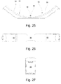
- the pads 53 and bridging support 54 may be manufactured as a one-piece unit. Figures 24 to 26 illustrate the support pads 53 and bridging support 54 when not mounted on the cradle 27.
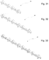
- a plurality of the cradles 27 can be linked together to form an array, on which a plurality of cylindrical containers can be stored. Links between the cradles 27 can comprise the linking regions referred to above. Alternatively, the cradles 27 can be linked together by creating multiple cradling regions 31 on a single, extended beam 28. Examples of this are illustrated in figures 28 to 33 . As described previously with respect to figure 13 , such arrays of cradles 27 can be connected together in two longitudinal arrangements. A first of the longitudinal arrangements 25 comprises a first plurality of cradles linked together end to end. A second of the longitudinal arrangements 26 comprises a second plurality of cradles linked together end to end.
- the two arrangements 25, 26 lie parallel to one another so that the cradles 1 in the first arrangement 25 support the first ends of a plurality of cylindrical storage containers and the cradles 1 in the second arrangement 26 support the second ends of the cylindrical storage containers (not shown).
- the longitudinal axes of the cylindrical storage containers are illustrated in figure 13 by dashed lines.
- the connected beams 2 of the cradles 1 in each arrangement 25, 26 run perpendicular to the longitudinal axes of the cylinders, both forward and aft of the cylinder bodies.
- the array allows for heavy cylindrical storage containers to be stacked in a close packed arrangement in long rows, for example mounted on concrete rafts.
- the design is such that it evenly distributes the weight of the cylinders directly into the ground for seismic and static load conditions.
- the welded stiffeners 37 in the beam 28 of each cradle 27 make use of standard plate construction that allows the load to be distributed to the ground in a manner that reduces the amount of bearing stress.
- Each cradle 27, as part of the array can accommodate the seismic and static loads produced by stacking a plurality of tiers of cylinders above, such as three tiers.
- the size of the array can easily be increased or reduced by linking more cradles 27 into the rows or by removing them using the readily accessible linking regions 42 previously described.
- the design of the linking regions 42 holds each cradle 27 in position and supports the horizontal loads that are imposed from having multiple levels of cylinders stacked on top of the cradles 27.
- the cradling system described above is capable of safely supporting cylindrical storage containers of material in three vertical tiers, as illustrated in figure 34 .
- a plurality of cylindrical storage containers C may be spaced apart by spacers S in a stacked vertical array.
- the spacers S may be formed of resilient plastics material and shaped to stably support the second and third tiers of containers C in the array.
- Each spacer C may, for example, comprise three concave surfaces as shown in figure 34 , the radii of which match the exterior radii of the longitudinal surfaces of the storage containers C.
- the mass of each cradle 1 may be relatively low, such as approximately 85kg, which makes for easier installation of the array 24. Once installed on concrete rafts, for example using conventional concrete anchors, the cradles 1 do not require maintenance over a twenty five year period.
- the system may be optimised and configured to store industry-standardised containers of uranium hexafluoride (UF6) in an indoor or outdoor environment.
- UF6 uranium hexafluoride
- Such containers are generally cylindrical in shape.
- Examples containers include the type 30B UF6 cylinder and the type 48Y UF6 cylinder.
Landscapes
- Engineering & Computer Science (AREA)
- Mechanical Engineering (AREA)
- Transportation (AREA)
- Pallets (AREA)
Abstract
A cradle (1, 27) for supporting a cylindrical storage container, comprising a longitudinal support member (2, 28) having at least one flange (4, 30), first and second angular supports (3, 29) forming a cradle region to support the container in a stable position above the at least one flange (4, 30), at least one first support pad (22, 53) located on a support surface (6, 32) of the first angular support; and at least one second support pad (22, 53) located on a support surface (6, 32) of the second angular support.
Description
- This specification relates to cradles for supporting cylindrical objects such as cylindrical storage containers.
- This specification provides a cradle for supporting a cylindrical storage container, comprising a longitudinal support member having at least one flange, first and second angular supports forming a cradle region to support the container in a stable position above the at least one flange, at least one first support pad located on a support surface of the first angular support and at least one second support pad located on a support surface of the second angular support.
- The at least one flange may comprise an upper flange and the support member may further comprise a lower flange.
- The support member may further comprise a web between the upper and lower flanges.
- The upper and lower flanges may be parallel to one another and may be perpendicular to the web.
- The support member may further comprise at least one web stiffener connected to the upper and lower flanges and the web.
- The at least one web stiffener may be welded to the upper and lower flanges and the web.
- The support member may comprise an I-beam.
- The support member may have an open section.
- The planes of the support surfaces of the first and second angular supports may diverge from one another with increasing perpendicular distance from the at least one flange.
- The first and second angular supports may be connected to an upper surface of the at least one flange.
- The first and second angular supports may be welded to an upper surface of the at least one flange.
- The first and second angular supports may each comprise a planar container support element and a planar bridging element connected between an underside of the container support element and the at least one flange.
- The planar bridging element may be welded between the underside of the container support element and the at least one flange.
- The support surface of the first angular support may be a surface of the planar support element of the first angular support; and the support surface of the second angular support may be a surface of the planar support element of the second angular support.
- The cradle may comprise a linking region for linking the cradle to a corresponding linking region of a neighbouring cradle.
- The linking region may comprise a planar linking element having at least one aperture for accommodating a linking pin.
- The linking pin may comprise a shear pin.
- The plane of the linking element may be perpendicular to the plane of the at least one flange.
- The linking region may comprise at least one linking plate for attaching the planar linking element to a planar linking element of a neighbouring cradle.
- The at least one linking plate may comprise at least one aperture for accommodating the linking pin so that the linking pin can be inserted through the at least one linking plate and the linking element to attach the at least one linking plate to the linking element.
- The cradle may comprise at least two of the at least one linking plates.
- A first of the linking plates may be attached to a first face of the linking element and a second of the linking plates may be attached to a second face of the linking element through the apertures in the linking plates and linking element.
- The first of the linking plates may be further attached to a first face of a linking element of a neighbouring cradle through a further aperture in the first linking plate and an aperture in the linking element of the neighbouring cradle.
- The second of the linking plates may be further attached to a second face of the linking element of the neighbouring cradle through a further aperture in the second linking plate and the aperture in the linking element of the neighbouring cradle.
- The linking plates may be attached to the linking element of the neighbouring cradle by inserting a further linking pin through the apertures.
- The further linking pin may comprise a shear pin.
- The first and second angular supports may be separated by a region of the longitudinal support member.
- The support member may be formed from a metallic material.
- The angular supports may be formed from a metallic material.
- The metallic material may be Standard Steel Grade S355.
- The at least one first support pad may be separated by a gap from the at least one second support pad.
- The at least one first support pad may be separate from the at least one second support pad.
- The cradle may further comprise a bridging support located between the at least one first support pad and the at least one second support pad.
- The at least one first support pad may be joined to the at least one second support pad by the bridging support.
- The bridging support may comprise a concave support surface for supporting a circumferential surface of a cylindrical storage container.
- The bridging support may be formed from a resilient and/or compliant plastics material.
- The at least one first support pad may comprise a concave support surface for supporting a circumferential surface of a cylindrical storage container.
- The at least one second support pad may comprise a concave support surface for supporting a circumferential surface of a cylindrical storage container.
- The at least one first and/or the at least one second support pad may comprise a concave support surface for supporting a non-conforming circumferential surface of a cylindrical storage container.
- The at least one first and second support pads may be formed from a resilient and/or compliant plastics material.
- This specification also provides a system for supporting a plurality of cylindrical storage containers, comprising a plurality of the cradles linked together to form at least two rows of cradling regions to support the forward and aft ends of the plurality of containers.
- For the purposes of example only, embodiments are described below with reference to the accompanying figures.
-
-
Figure 1 is a perspective view of a cradle for supporting a cylindrical storage container; -
figure 1A is a perspective view of a linking plate of a linking region of a cradle for supporting a cylindrical storage container; -
figure 2 is a side-on view of a cradle for supporting a cylindrical storage container; -
figure 3 is a top-down view of a cradle for supporting a cylindrical storage container; -
figure 4 is an end-on view of a cradle for supporting a cylindrical storage container; -
figure 5 is a perspective view of a cradle for supporting a cylindrical storage container, including a pair of container support pads; -
figure 6 is a side-on view of a cradle for supporting a cylindrical storage container, including a pair of container support pads; -
figure 7 is a top-down view of a cradle for supporting a cylindrical storage container, including a pair of container support pads; -
figure 8 is an end-on view of a cradle for supporting a cylindrical storage container, including a pair of container support pads; -
figure 9 is a perspective view of a container support pad of a cradle for supporting a cylindrical storage container; -
figure 10 is a side-on view of a container support pad of a cradle for supporting a cylindrical storage container; -
figure 11 is a top-down view of a container support pad of a cradle for supporting a cylindrical storage container; -
figure 12 is a front-on view of a container support pad of a cradle for supporting a cylindrical storage container; -
figure 13 is an illustration of a pair of rows of linked cradles for supporting a plurality of cylindrical storage containers; -
figure 14 illustrates specific example dimensions and geometries for a cradle for supporting a cylindrical storage container; and -
figure 15 illustrates specific example dimensions and geometries for an angular support and support pad of a cradle for supporting a cylindrical storage container; -
figure 16 is a perspective view of a cradle for supporting a cylindrical storage container; -
figure 16A is a perspective view of a linking plate of a linking region of a cradle for supporting a cylindrical storage container; -
figure 16B is a perspective view of a pin for securing at least one linking plate to at least one cradle for supporting a cylindrical storage container; -
figure 16C is a perspective view of a locking pin for securing a pin such as that shown in -
figure 16B in a linking region of at least one cradle for supporting a cylindrical storage container; -
figure 17 is a side-on view of a cradle for supporting a cylindrical storage container; -
figure 18 is a top-down view of a cradle for supporting a cylindrical storage container; -
figure 19 is an end-on view of a cradle for supporting a cylindrical storage container; -
figure 20 is a perspective view of a cradle for supporting a cylindrical storage container, including a container support pad; -
figure 21 is a side-on view of a cradle for supporting a cylindrical storage container, including a container support pad; -
figure 22 is a top-down view of a cradle for supporting a cylindrical storage container, including a container support pad; -
figure 23 is an end-on view of a cradle for supporting a cylindrical storage container, including a container support pad; -
figure 24 is a perspective view of a container support pad of a cradle for supporting a cylindrical storage container; -
figure 25 is a side-on view of a container support pad of a cradle for supporting a cylindrical storage container; -
figure 26 is an underside view of a container support pad of a cradle for supporting a cylindrical storage container; -
figure 27 is a rear-on view of a container support pad of a cradle for supporting a cylindrical storage container; -
figure 28 is an illustration of two joined cradles for supporting two cylindrical storage containers; -
figure 29 is an illustration of three joined cradles for supporting three cylindrical storage containers; -
figure 30 is an illustration of four joined cradles for supporting four cylindrical storage containers; -
figure 31 is an illustration of two joined cradles for supporting two cylindrical storage containers, each cradle including a container support pad; -
figure 32 is an illustration of three joined cradles for supporting three cylindrical storage containers, each cradle including a container support pad; and -
figure 33 is an illustration of four joined cradles for supporting four cylindrical storage containers, each cradle including a container support pad -
figure 34 illustrates a cradling system supporting cylindrical storage containers in three vertical tiers. - A cradle for supporting a generally cylindrical container of material in a stable position is described below. The
cradle 1 may be used as part of an array of cradles for supporting a large number of containers in a close packed configuration. - Referring to
figure 1 , thecradle 1 comprises a support member in the form of abeam 2 and twoangular supports 3 for supporting a cylindrical storage container above thebeam 2. The angular supports 3 are located in a spaced-apart arrangement on anupper surface 4 of thebeam 2. The region between theangular supports 3 is acradling region 5, in which a container of material can be safely accommodated for short, medium and long term storage. - In use, the direction of the
beam 2 is perpendicular to the longitudinal axis of the container so that thebeam 2 passes underneath the container in a transverse direction to support the container against gravity. In addition to supporting the container against gravity, thecradling region 5 is arranged to prevent the container from rolling or otherwise moving in a lateral direction relative to thebeam 2. - As shown in
figure 1 , theangular supports 3 of thecradling region 5 each comprises asupport face 6 which is non-perpendicular to theupper surface 4 of thebeam 2. The support faces 6 diverge from one another with increasing height above thebeam 2, so that with increasing vertical distance from theupper surface 4 of thebeam 2 the distance between the support faces 6 increases. The angles of the support faces 6 relative to theupper surface 4 of thebeam 2 form a well between theangular supports 3, the geometry of which is appropriate for stably supporting the cylindrical container. - A more detailed discussion of the individual elements of the
cradle 1 and its construction is provided below. - As best illustrated in
figures 1 and4 , thebeam 2 comprises three principal elements: A planar upper element, a planar lower element and a planar bridging element which connects the upper and lower elements together. The upper element is referred to below as anupper flange 7 and the lower element is referred to below as alower flange 8. The bridging element is referred to as aweb 9. The upper andlower flanges web 9 is perpendicular to theflanges flanges web 9 is such that thebeam 2 has an I-shaped cross-section when viewed end-on, and may be referred to as an I-beam. - In addition to its three
principal elements beam 2 may comprise one or more further structural supports which bridge between the upper andlower flanges more web stiffeners 10 of the type illustrated infigures 1 and 2 . For example, thebeam 2 illustrated infigures 1 and 2 comprises twelvesuch web stiffeners 10 connected between the upper andlower flanges web 9. Sixstiffeners 10 are provided on each side of theweb 9. - The
web stiffeners 10 are planar elements that are perpendicular to the planes of both the upper andlower flanges web 9. As shown infigures 1 and3 , one or more of theweb stiffeners 10 may project outwards beyond the longitudinal edges of the upper andlower flanges cradle 1 is viewed from above. These projectingweb stiffeners 10 may each be associated with afurther element 11 for securing thebeam 2 to a floor, such as a concrete raft. - As shown in
figure 1 , theelements 11 for securing thecradle 1 to the floor may each comprise a plate or otherwise planar element which lies parallel to the floor and which can be fixed thereto. The plane of the securingelements 11 is parallel to the planes of the upper andlower flanges web 9 andweb stiffeners 10. As best shown infigures 1 and4 , the upper faces 12 of the securingelements 11 may be fixed to thelower edges 13 of the projectingweb stiffeners 10 so that each projectingweb stiffener 10 extends across the approximate centre of its associated securingelement 11. Each securingelement 11 may comprise one or more fixings by which theelement 11 can be affixed to the floor. For example, the securingelements 11 illustrated infigures 1 and3 each comprise twoapertures 14 through which theelements 11 can be bolted or otherwise fixed into mountings located on the floor. - The
beam 2 also comprises a linkingregion 15 for linking thebeam 2 to the beam of an adjacent cradle. The linkingregion 15 may be provided at one or both ends of thebeam 2 so that a plurality ofcradles 1 can be linked together in a row. An example of alinking region 15 is illustrated infigures 1 to 4 . Thecradle 1 shown in these figures comprises a linkingregion 15 at each end of thebeam 2. The linkingregion 15 comprises aplanar linking element 16 which projects perpendicularly outwards from aweb stiffener 10 at the end of thebeam 2. The linkingelement 16 may be attached to thisweb stiffener 10 or may alternatively be attached to anextended region 17 of thelower flange 8. As a further alternative, the linkingelement 16 may be attached to both theweb stiffener 10 and theextended region 17 of thelower flange 8, as best shown infigure 1 . The plane of the linkingelement 16 may be parallel to the plane of theweb 9 previously described. Indeed, as shown infigure 1 , the plane of the linkingelement 16 may be the same as the plane of theweb 9. - The linking
element 16 comprises one or more fixings by which theelement 16 can be affixed to a corresponding linking element of a neighbouring cradle. For example, as illustrated infigures 1 and 2 , the linkingelement 16 may comprise anaperture 18 to which a linkage, shown infigure 1A , can be attached to link thecradle 1 to the linking element of the neighbouring cradle. A suitable linkage comprises one ormore linkage plates 16A fabricated from a suitable material such as structural steel. Thelinkage plates 16A are pinned, for example using shear pins, through theapertures 18 of the twoadjacent linking elements 16. Alinkage plate 16A may be provided on both sides of the linkingelements 16 in order to reinforce the link between the neighbouringcradles 1. In this configuration, the shear pins pin thelinkage plates 16 together, sandwiching the linkingelements 16 between them. The configuration of thelinkage region 16 is advantageous because it distributes the load into thebeam 2 and through thecradles 1 in an effective manner. - It will be appreciated that the nature of the linking
region 15 is such that it is easily accessible from the top and sides of thecradle 1 and therefore can be used to attach cradles together quickly and without the need for complex equipment. This is advantageous at least because it allows a large array of the cradles to be assembled in an efficient and responsive manner when further container storage capacity is required. - Referring back to
figure 1 , theangular supports 3 each comprise acontainer support element 19, which includes thesupport face 6 referred to previously, and one or more further support elements connected between thecontainer support element 19 and theupper surface 4 of theupper flange 7 of thebeam 2. As best shown infigures 1 and 2 , thecontainer support element 19 is planar and extends from theupper surface 4 of theupper flange 7 at an angle to define a triangular region between its underside and theupper flange 7. In this triangular region, a first of the further support elements comprises aplanar bridging element 20 connected between the underside of thecontainer support element 19 and theupper surface 4 of theupper flange 7. The bridgingelement 20 has a triangular shape so as to fit within the triangular region. The plane of the bridgingelement 20 is parallel to the plane of theweb 9 and perpendicular to the plane of theupper flange 7. Indeed, the plane of the bridgingelement 20 may the same as the plane of theweb 9 previously discussed. The bridgingelement 20 at least partly bears the load of the container by bracing thecontainer support element 19 against the force exerted by the container. - The angular supports 3 may also comprise one or more further bracing supports 21. These bracing supports 21 act to further brace the angled
container support element 19 against the load exerted by the container in thecradling region 5. Examples of the further bracing supports 21 are illustrated infigures 1 and 2 as planar elements connected between theupper surface 4 of theupper flange 7 and the underside of thecontainer support element 19. For example, referring tofigure 1 , eachangular support 3 may comprise two such further bracingsupports 21 extending perpendicularly from the underside of thecontainer support element 19 to theupper surface 4 of theupper flange 7 on either side of thetriangular bridging support 20 described above. The planes of the further bracingsupports 21 of eachangular support 3 are approximately parallel to one another and approximately perpendicular to the plane of thecontainer support element 19. - The elements of the
cradle 1 described above, including elements of thebeam 2,angular supports 3 and linkingregions 15, are formed from a metallic material such as steel. An example of a suitable steel is Standard Steel Grade S355. Unless otherwise described, the points of contact between the individual elements of thecradle 1 may comprise permanent welds to form a strong and resilient cradle structure. The welds may be made using an autonomous manufacturing technique such as robotic manufacture. The relatively small number of elements means that the amount of welding required to assemble thecradle 1 is small and can be carried out relatively quickly. This is aided by the open section nature of thecradle 1, which makes for excellent accessibility to the welding points. - As will be appreciated from
figures 1 to 4 and the description above, thecradle 1 has minimal locations in which debris and/or water could accumulate. This is advantageous because it allows thecradle 1 to be installed in an outside location and to be exposed to all weather conditions without significant concern for the effects that the accumulation of environmental debris such as dead leaves or litter may have on the structure. - Referring to
figures 5 to 8 , thecradle 1 may further comprise asupport pad 22 located against thesupport face 6 of eachangular support 3. Thesupport pads 22 substantially cover the support faces 6 of theangular supports 3 and are the regions of thecradle 1 which contact the peripheral walls of the container to support it in thecradling region 5. In addition to being located against the support surfaces 6 of theangular supports 3, thepads 22 may also be located against a partial region of theupper face 4 of theupper flange 7 between the twoangular supports 3. Thesupport pads 22 can be fixed to theangular supports 3 using any suitable method, such as pinning thepads 22 directly into thecontainer support elements 19. Thesupport pads 22 may also be fixed to theupper flange 7 in a similar manner. - As best illustrated in
figures 5 and 6 , thesupport pads 22 may comprise aconcave support surface 23 against which the circumferential wall of a container lies when located in thecradle 1. The degree of curvature in theconcave surface 23 may be selected so as to match the radius of curvature of the container to be supported. - A function of the
support pads 22 is to aid even distribution of the load of the container into thecradle 1. Another function of thesupport pads 22 is to allow for increased installation tolerances, for example when thecradles 1 are mounted to a floor. These functions may be aided by a degree of flexibility in the structure and/or material of thepads 22. An example of a suitable material for thepads 22 is a resilient and/or compliant plastics material. Thepads 22 may be solid or may be to some extent hollow.Figures 9 to 12 illustrate thesupport pads 22 when not mounted on thecradle 1. - As outlined briefly above, a plurality of the
cradles 1 can be linked together to form an array, on which a plurality of cylindrical containers can be stored. A section of such anarray 24 is illustrated schematically infigure 13 , which shows a plurality ofcradles 1 connected together in two longitudinal arrangements. A first of thelongitudinal arrangements 25 comprises a first plurality ofcradles 1 linked together end to end. A second of thelongitudinal arrangements 26 comprises a second plurality ofcradles 1 linked together end to end. The twoarrangements cradles 1 in thefirst arrangement 25 support the first ends of a plurality of cylindrical storage containers and thecradles 1 in thesecond arrangement 26 support the second ends of the cylindrical storage containers (not shown). The longitudinal axes of the cylindrical storage containers are illustrated infigure 13 by dashed lines. Theconnected beams 2 of thecradles 1 in eacharrangement - The
array 24 allows for heavy cylindrical storage containers to be stacked in a close packed arrangement in long rows, for example mounted on concrete rafts. The design is such that it evenly distributes the weight of the cylinders directly into the ground for seismic and static load conditions. The weldedstiffeners 10 in thebeam 2 of eachcradle 1 make use of standard plate construction that allows the load to be distributed to the ground in a manner that reduces the amount of bearing stress. Eachcradle 1, as part of thearray 24, can accommodate the seismic and static loads produced by stacking a plurality of tiers of cylinders above, such as three tiers. It will be appreciated that the size of thearray 24 can easily be increased or reduced by linkingmore cradles 1 into the rows or by removing them using the readilyaccessible linking regions 15 previously described. The design of the linkingregions 15 holds eachcradle 1 in position and supports the horizontal loads that are imposed from having multiple levels of cylinders stacked on top of thecradles 1. -
Figures 14 and15 illustrate specific example dimensions and geometries for thebeam 2,angular supports 3 andsupport pads 22.
Further examples cradles for supporting a generally cylindrical container of material in a stable position are described below. As with thecradles 1 described with respect tofigures 1 to 15 , the cradles described below may be used as part of an array of cradles for supporting a large number of containers in a close packed configuration. Many aspects of the cradles described below are interchangeable with corresponding aspects of thecradles 1 described with respect tofigures 1 to 15 , as will be implicitly evident to the skilled person and explicitly evident from the following description. - Referring to
figure 16 , a further example of acradle 27 comprises a support member in the form of abeam 28 and twoangular supports 29 for supporting a cylindrical storage container above thebeam 28. As with thecradle 1 illustrated in, for example,figure 1 the angular supports 29 are located in a spaced-apart arrangement on anupper surface 30 of thebeam 28. The region between theangular supports 29 is acradling region 31, in which a container of material can be safely accommodated for short, medium and long term storage. - As with the cradles previously described, in use the direction of the
beam 28 is perpendicular to the longitudinal axis of the container so that thebeam 28 passes underneath the container in a transverse direction to support the container against gravity. In addition to supporting the container against gravity, thecradling region 31 is arranged to prevent the container from rolling or otherwise moving in a lateral direction relative to thebeam 28. - The angular supports 29 of the
cradling region 31 each comprises asupport face 32 which is non-perpendicular to theupper surface 30 of thebeam 28. The support faces 32 diverge from one another in the manner described above in relation to the support faces 6 shown infigure 1 , so that the support faces 32 form a well between the angular supports 29. The geometry of this well is appropriate for stably supporting the cylindrical container. The support faces 32 shown infigure 16 differ from those described with respect tofigure 1 by a plurality ofrecesses 33 in the periphery of eachsupport face 32. Therecesses 33 may, for example, each comprise an approximately rectangular cut-out in the edge of thesupport face 32, as exemplified by the fiverectangular recesses 33 illustrated infigure 16 . - The
beam 28 substantially corresponds to thebeam 2 described previously with respect tofigure 1 . Thebeam 28 includes a planar upper element, a planar lower element and a planar bridging element in the form of anupper flange 34, alower flange 35 and aweb 36. The geometrical relationships between theseelements flanges web 9 previously described, such that thebeam 28 may be referred to as an I-beam. - As with the
beam 2 described previously, thebeam 28 may also comprise one or more further structural supports in the form ofweb stiffeners 37 which bridge between the upper andlower flanges beam 28 illustrated infigures 16 and17 comprises 16such web stiffeners 37, with eightstiffeners 36 being provided on each side of theweb 36. - The
web stiffeners 37 correspond to theweb stiffeners 10 previously described. As in thecradles 1 described above, one or more of theweb stiffeners 37 project outwards beyond the longitudinal edges of the upper andlower flanges cradle 1 is viewed from above. As shown infigure 16 , these projectingweb stiffeners 37 may each be associated with afurther element 38 for securing thebeam 28 to a floor, such as a concrete raft. Thefurther elements 38 substantially correspond to thefurther elements 11 described above with respect tofigure 1 . Eachelement 38 may includeapertures 39 through which theelements 38 can be bolted or otherwise fixed into mountings located on the floor. - Additionally, unlike the projecting
web stiffeners 10 shown infigure 1 , the projectingweb stiffeners 37 of this example may each comprise anupper flange 40. Theupper flange 40 of each projectingweb stiffener 37 is substantially co-planar with theupper flange 34 of thebeam 28 and parallel with thefurther element 38 for securing thebeam 28 to the floor. - Referring again to
figure 16 , a linkingregion 41 at one or both ends of thebeam 28 is similar to the linkingregions 15 discussed previously in relation tofigures 1 to 4 . As with the previously described examples, the linkingregion 15 comprises aplanar linking element 42 which projects perpendicularly outwards from aweb stiffener 37 at the end of thebeam 2. As shown infigure 16 , the linkingelement 42 is attached to at least one of theweb stiffener 37, anextended region 43 of thelower flange 35 of thebeam 28 and anextended region 44 of theupper flange 34 of thebeam 28. The linkingelement 42 may be attached to any combination of these threeelements beam 28, for example by suitable welds. Alternatively, linkingelement 42 may be of one-piece construction (e.g. a one-piece casting) with the extensions of the upper andlower flanges figure 16 . The plane of the linkingelement 42 may be parallel to, or the same as, the plane of theweb 36 of thebeam 28. - The linking
element 42 comprises one or more fixings by which theelement 42 can be affixed to a corresponding linking element of a neighbouring cradle. For example, as illustrated infigures 16 and17 , the linkingelement 42 may comprise anaperture 45 to which a linkage can be attached to link thecradle 27 to the linking element of the neighbouring cradle. Theaperture 45 and the linkage may substantially correspond to theaperture 18 described previously with respect tofigure 1 and the linkage described previously with respect tofigure 1A . For example, a suitable linkage comprises one ormore linkage plates 46 fabricated from a suitable material such as structural steel. Thelinkage plates 46 are pinned, for example using shear pins, through theapertures 45 of the twoadjacent linking elements 42. Alinkage plate 46 may be provided on both sides of the linkingelements 42 in order to reinforce the link between the neighbouringcradles 27. In this configuration, thepins 47 pin thelinkage plates 46 together, sandwiching the linkingelements 42 between them. As with the linkingregion 16 described previously with respect tofigure 1 , the configuration of the linkingregion 41 is advantageous because it distributes the load into thebeam 2 and through thecradles 27 in an effective manner. An example of thelinkage plate 46 is shown infigure 16A and an example of apin 47 for attaching theplate 46 to the linkingelement 42 is shown infigure 16B . Thispin 47 may be a shear pin.Figure 16C illustrates an example of a lockingpin 48 which can be passed diametrically throughdiametric bores 49 at either end of thepin 47 to ensure that thepin 47 remains in place in the linkingregion 42. The lockingpin 48 comprises a right-angled bend to prevent it from falling out of thebore 49 accidentally. - As with the linking
region 15 described previously, the nature of the linkingregion 42 is such that it is easily accessible from the top and sides of thecradle 27 and therefore can be used to attach cradles together quickly and without the need for complex equipment. - Referring back to
figure 16 , the angular supports 29 each comprise acontainer support element 50 which substantially corresponds to thecontainer support elements 19 discussed with respect to previous examples of thecradle 1. Thecontainer support elements 50 include the container support faces 32 referred to previously. Similarly, as with previous examples, the angular supports 29 also include one or morefurther support elements container support element 50 and theupper surface 30 of theupper flange 34 of thebeam 28. - As best shown in
figures 16 and17 , thecontainer support element 50 is planar and extends from theupper surface 30 of theupper flange 34 at an angle to define a triangular region between its underside and theupper flange 34. In this triangular region, a first of the further support elements comprises aplanar bridging element 51 connected between the underside of thecontainer support element 50 and theupper surface 30 of theupper flange 34. The bridgingelement 51 corresponds to the bridgingelement 20 previously discussed in relation tofigure 2 . As previously described, the bridgingelement 51 at least partly bears the load of the container by bracing thecontainer support element 50 against the force exerted by the container. - The angular supports 29 may also comprise one or more further bracing supports 52. As with the further bracing supports 21 described previously, these bracing
supports 52 act to further brace the angledcontainer support element 50 against the load exerted by the container in thecradling region 31. Examples of the further bracing supports 52 are illustrated infigures 16 and17 as planar elements connected between theupper surface 30 of theupper flange 34 of thebeam 28 and the underside of thecontainer support element 50. For example, referring tofigure 16 , eachangular support 29 may comprise two such further bracingsupports 52 extending perpendicularly from the underside of thecontainer support element 50 to theupper surface 30 of theupper flange 34 of thebeam 28 on either side of thetriangular bridging element 51 referred to above. As with previously described examples, the planes of the further bracingsupports 52 of eachangular support 29 are approximately parallel to one another and approximately perpendicular to the plane of theplanar bridging element 51. - As best shown in
figure 16 , unlike the further bracingsupports 21 illustrated infigure 1 , one or more of the further bracingsupports 52 in this example of thecradle 27 may extend beyond the longitudinal peripheries of thecontainer support element 50 andupper flange 34 of thebeam 28. In so doing, the bottom edge of this further bracingsupport 52 may extend onto theupper flange 40 of the projectingweb stiffeners 37 described above, on both sides of thebeam 28, thereby further distributing the load exerted on theangular support 29 by the container in thecradling region 31. - As with the element of the
cradle 1 already discussed, the elements of thecradle 27, including elements of thebeam 28,angular supports 29 and linkingregions 41, are formed from a metallic material such as steel. An example of a suitable steel is Standard Steel Grade S355. Unless otherwise described, the points of contact between the individual elements of thecradle 27 may comprise permanent welds to form a strong and resilient cradle structure. The welds may be made using an autonomous manufacturing technique such as robotic manufacture. The relatively small number of elements means that the amount of welding required to assemble thecradle 1 is small and can be carried out relatively quickly. This is aided by the open section nature of thecradle 27, which makes for excellent accessibility to the welding points. - As will be appreciated from, for example,
figures 16 to 20 and the description above, thecradle 27 has minimal locations in which debris and/or water could accumulate. This provides at least the advantages previously discussed. - Referring to
figures 20 to 27 , thecradle 1 may further comprise first andsecond support pads 53 respectively located against the support faces 32 of theangular support 29. Thesupport pads 53 substantially cover the support faces 32 of the angular supports 29 and are the region of thecradle 27 which contact the peripheral walls of the container to support it in thecradling region 31. Thesupport pads 53 perform a corresponding function to thesupport pads 22 described above with respect to previous examples. - The
support pads 53 are joined together by a bridgingsupport 54, which spans the region of thecradle 27 in between the angular supports 29. The bridgingsupport 54 is located against the section of theupper face 30 of theupper flange 34 of thebeam 28 in between the twoangular supports 29. As best shown infigures 20 and22 , the first andsecond pads 53 and the bridgingsupport 54 may together substantially cover theupper face 30 of theupper flange 34 of thebeam 28 in the region between the twoangular supports 29. - As shown in
figures 20, 21 ,24 and25 , and as with the examples discussed previously, thesupport pads 53 may each comprise aconcave support surface 55 against which the circumferential wall of a container lies when located in thecradle 27. The degree of curvature in theconcave surface 55 may be selected so as to match the radius of curvature of the container to be supported. Similarly, bridgingsupport 54 may also comprise aconcave support surface 56 having a radius of curvature selected to match the radius of curvature of the container to be supported. As illustrated infigure 25 , the shape of thesupport surface 56 of the bridgingsupport 54 may be an approximate arc and the radius of curvature of this arc may be substantially equal to the radius of the container. - In this configuration, the support surfaces 55, 56 of the
support pads 53 and the bridgingsupport 54 may together provide a contiguous and substantially unbroken support surface that matches and continuously follows the shape of the container when the container sits in thecradling region 31. - As with the
pads 22 previously discussed, thesupport pads 53 can be fixed to the angular supports 29 using any suitable method, such as by clipping or pinning thepads 53 directly to thecontainer support elements 50. The bridgingsupport 54 may also be fixed to theupper flange 34 in a similar manner. - As with the examples previously described, a function of the
support pads 53 is to aid even distribution of the load of the container into thecradle 27. The bridgingsupport 54 may further aid this load distribution into thecradle 27. Another function of thesupport pads 53 and bridgingsupport 54 is to allow for increased installation tolerances, for example when thecradles 27 are mounted to a floor. These functions may be aided by a degree of flexibility in the structure and/or material of thepads 53 and the bridgingsupport 54. An example of a suitable material for thepads 53 and bridgingsupport 54 is a resilient and/or compliant plastics material. Thepads 53 and bridgingsupport 54 may be solid or may be to some extent hollow. Thepads 53 and bridgingsupport 54 may be manufactured as a one-piece unit.Figures 24 to 26 illustrate thesupport pads 53 and bridgingsupport 54 when not mounted on thecradle 27. - As already outlined above with respect to the previous examples, a plurality of the
cradles 27 can be linked together to form an array, on which a plurality of cylindrical containers can be stored. Links between thecradles 27 can comprise the linking regions referred to above. Alternatively, thecradles 27 can be linked together by creatingmultiple cradling regions 31 on a single, extendedbeam 28. Examples of this are illustrated infigures 28 to 33 . As described previously with respect tofigure 13 , such arrays ofcradles 27 can be connected together in two longitudinal arrangements. A first of thelongitudinal arrangements 25 comprises a first plurality of cradles linked together end to end. A second of thelongitudinal arrangements 26 comprises a second plurality of cradles linked together end to end. The twoarrangements cradles 1 in thefirst arrangement 25 support the first ends of a plurality of cylindrical storage containers and thecradles 1 in thesecond arrangement 26 support the second ends of the cylindrical storage containers (not shown). The longitudinal axes of the cylindrical storage containers are illustrated infigure 13 by dashed lines. Theconnected beams 2 of thecradles 1 in eacharrangement - As previously described, the array allows for heavy cylindrical storage containers to be stacked in a close packed arrangement in long rows, for example mounted on concrete rafts. The design is such that it evenly distributes the weight of the cylinders directly into the ground for seismic and static load conditions. The welded
stiffeners 37 in thebeam 28 of eachcradle 27 make use of standard plate construction that allows the load to be distributed to the ground in a manner that reduces the amount of bearing stress. Eachcradle 27, as part of the array, can accommodate the seismic and static loads produced by stacking a plurality of tiers of cylinders above, such as three tiers. It will be appreciated that the size of the array can easily be increased or reduced by linking more cradles 27 into the rows or by removing them using the readilyaccessible linking regions 42 previously described. The design of the linkingregions 42 holds eachcradle 27 in position and supports the horizontal loads that are imposed from having multiple levels of cylinders stacked on top of thecradles 27. - The cradling system described above is capable of safely supporting cylindrical storage containers of material in three vertical tiers, as illustrated in
figure 34 . As shown infigure 34 , a plurality of cylindrical storage containers C may be spaced apart by spacers S in a stacked vertical array. The spacers S may be formed of resilient plastics material and shaped to stably support the second and third tiers of containers C in the array. Each spacer C may, for example, comprise three concave surfaces as shown infigure 34 , the radii of which match the exterior radii of the longitudinal surfaces of the storage containers C. The mass of eachcradle 1 may be relatively low, such as approximately 85kg, which makes for easier installation of thearray 24. Once installed on concrete rafts, for example using conventional concrete anchors, thecradles 1 do not require maintenance over a twenty five year period. - The system may be optimised and configured to store industry-standardised containers of uranium hexafluoride (UF6) in an indoor or outdoor environment. Such containers are generally cylindrical in shape. Examples containers include the type 30B UF6 cylinder and the type 48Y UF6 cylinder.
- The alternatives described above can be used singly or in combination.
Claims (15)
- A cradle for supporting a cylindrical storage container, comprising:a longitudinal support member having at least one flange;first and second angular supports forming a cradle region to support the container in a stable position above the at least one flange;at least one first support pad located on a support surface of the first angular support; andat least one second support pad located on a support surface of the second angular support.
- A cradle according to claim 1, wherein the at least one flange comprises an upper flange and the support member further comprises a lower flange.
- A cradle according to claim 2, wherein the support member further comprises a web between the upper and lower flanges.
- A cradle according to any preceding claim, wherein the planes of the support surfaces of the first and second angular supports diverge from one another with increasing perpendicular distance from the at least one flange.
- A cradle according to any preceding claim, wherein the first and second angular supports each comprises a planar container support element and a planar bridging element welded between an underside of the container support element and the at least one flange.
- A cradle according to any preceding claim, comprising a linking region for linking the cradle to a corresponding linking region of a neighbouring cradle.
- A cradle according to any preceding claim, wherein the first and second angular supports are separated by a region of the longitudinal support member.
- A cradle according to any preceding claim, wherein the at least one first support pad is separated by a gap from the at least one second support pad.
- A cradle according to any preceding claim, wherein the first support pad is separate from the second support pad.
- A cradle according to any of claims 1 to 7, further comprising a bridging support located between the at least one first support pad and the at least one second support pad.
- A cradle according to claim 10, wherein the at least one first support pad is joined to the at least one second support pad by the bridging support.
- A cradle according to claim 10 or 11, wherein the bridging support comprises a concave support surface for supporting a circumferential surface of a cylindrical storage container.
- A cradle according to any preceding claim, wherein the at least one first support pad comprises a concave support surface for supporting a circumferential surface of a cylindrical uranium storage container.
- A cradle according to any preceding claim, wherein the at least one second support pad comprises a concave support surface for supporting a circumferential surface of a cylindrical uranium storage container.
- A system for supporting a plurality of cylindrical storage containers, comprising a plurality of cradles as claimed in any preceding claim linked together to form at least two rows of cradling regions to support the forward and aft ends of the plurality of containers.
Applications Claiming Priority (1)
| Application Number | Priority Date | Filing Date | Title |
|---|---|---|---|
| GB1503599.1A GB2536013A (en) | 2015-03-03 | 2015-03-03 | Cradling cylindrical objects |
Publications (1)
| Publication Number | Publication Date |
|---|---|
| EP3064451A1 true EP3064451A1 (en) | 2016-09-07 |
Family
ID=52876448
Family Applications (1)
| Application Number | Title | Priority Date | Filing Date |
|---|---|---|---|
| EP16158427.1A Withdrawn EP3064451A1 (en) | 2015-03-03 | 2016-03-03 | Cradle for cylindrical objects and system therewith |
Country Status (2)
| Country | Link |
|---|---|
| EP (1) | EP3064451A1 (en) |
| GB (1) | GB2536013A (en) |
Cited By (7)
| Publication number | Priority date | Publication date | Assignee | Title |
|---|---|---|---|---|
| CN108177588A (en) * | 2017-12-28 | 2018-06-19 | 浙江双友物流器械股份有限公司 | A steel coil positioning bracket |
| CN110734012A (en) * | 2019-10-18 | 2020-01-31 | 中船澄西船舶修造有限公司 | A forklift transport anti-skid tooling for forklift cable transporter |
| CN112644884A (en) * | 2020-12-05 | 2021-04-13 | 安徽坤源铝业有限公司 | Anti-rolling supporting and storing device for aluminum coil |
| US20220082212A1 (en) * | 2020-09-15 | 2022-03-17 | Hyundai Mobis Co., Ltd. | Apparatus for fixing pressure vessel |
| KR20220036463A (en) * | 2020-09-15 | 2022-03-23 | 현대모비스 주식회사 | Apparatus for fixating pressure vessel |
| EP4206461A1 (en) * | 2021-12-30 | 2023-07-05 | Nordex Energy Spain, S.A.U. | Support element for a segment of wind turbine towers, support system comprising at least a support element and method of supporting at least a segment of wind turbine towers |
| CN117622703A (en) * | 2023-11-16 | 2024-03-01 | 北京航星机器制造有限公司 | A multi-support quick-locking upper loading platform |
Families Citing this family (4)
| Publication number | Priority date | Publication date | Assignee | Title |
|---|---|---|---|---|
| CA2999028A1 (en) * | 2016-11-14 | 2018-05-14 | Robin WILKERSON | Transportation load securing system |
| CN106494752A (en) * | 2016-12-29 | 2017-03-15 | 泰州前进科技有限公司 | A kind of support tank frame |
| CN109717677A (en) * | 2017-10-30 | 2019-05-07 | 江苏中天华宇智能科技有限公司 | Tranquilizer |
| CN108950163B (en) * | 2018-09-18 | 2024-06-04 | 张化机(苏州)重装有限公司 | Adjustable support for supporting cylinder |
Citations (6)
| Publication number | Priority date | Publication date | Assignee | Title |
|---|---|---|---|---|
| GB1225817A (en) * | 1968-05-22 | 1971-03-24 | ||
| CN1640787A (en) * | 2004-01-09 | 2005-07-20 | 神原汽船株式会社 | Heavy goods carrying table and method for using same |
| US20090226275A1 (en) * | 2008-03-07 | 2009-09-10 | Hae Su Jung | Metal conduit inserted monomer cast nylon support block producing method and monomer cast nylon support block producing thereof |
| DE202011003305U1 (en) * | 2011-02-28 | 2011-09-01 | Ren An Technology Material Ind Co., Ltd. | Roll-off protection for steel rollers |
| DE202011106828U1 (en) * | 2010-10-27 | 2012-02-17 | Fritz Schäfer GmbH | Shelf for holding barrels, especially wooden barrels |
| JP5030032B1 (en) * | 2012-02-18 | 2012-09-19 | 株式会社ロジカル | Drum rail |
Family Cites Families (4)
| Publication number | Priority date | Publication date | Assignee | Title |
|---|---|---|---|---|
| US5370245A (en) * | 1992-04-03 | 1994-12-06 | The Bottle Buddy, Inc. | Water cooler bottle storage stand and system |
| US7306415B2 (en) * | 2003-05-19 | 2007-12-11 | Ttx Company | Clamping system and method for securing freight |
| US8231027B2 (en) * | 2007-11-09 | 2012-07-31 | Jui Te Wang | Vacuum container having air release valve cover |
| US20150097098A1 (en) * | 2013-10-03 | 2015-04-09 | Jimmy Chi | Steel coil protection structure |
-
2015
- 2015-03-03 GB GB1503599.1A patent/GB2536013A/en not_active Withdrawn
-
2016
- 2016-03-03 EP EP16158427.1A patent/EP3064451A1/en not_active Withdrawn
Patent Citations (6)
| Publication number | Priority date | Publication date | Assignee | Title |
|---|---|---|---|---|
| GB1225817A (en) * | 1968-05-22 | 1971-03-24 | ||
| CN1640787A (en) * | 2004-01-09 | 2005-07-20 | 神原汽船株式会社 | Heavy goods carrying table and method for using same |
| US20090226275A1 (en) * | 2008-03-07 | 2009-09-10 | Hae Su Jung | Metal conduit inserted monomer cast nylon support block producing method and monomer cast nylon support block producing thereof |
| DE202011106828U1 (en) * | 2010-10-27 | 2012-02-17 | Fritz Schäfer GmbH | Shelf for holding barrels, especially wooden barrels |
| DE202011003305U1 (en) * | 2011-02-28 | 2011-09-01 | Ren An Technology Material Ind Co., Ltd. | Roll-off protection for steel rollers |
| JP5030032B1 (en) * | 2012-02-18 | 2012-09-19 | 株式会社ロジカル | Drum rail |
Cited By (12)
| Publication number | Priority date | Publication date | Assignee | Title |
|---|---|---|---|---|
| CN108177588A (en) * | 2017-12-28 | 2018-06-19 | 浙江双友物流器械股份有限公司 | A steel coil positioning bracket |
| CN108177588B (en) * | 2017-12-28 | 2020-04-10 | 浙江双友物流器械股份有限公司 | Steel coil positioning support |
| CN110734012A (en) * | 2019-10-18 | 2020-01-31 | 中船澄西船舶修造有限公司 | A forklift transport anti-skid tooling for forklift cable transporter |
| US20220082212A1 (en) * | 2020-09-15 | 2022-03-17 | Hyundai Mobis Co., Ltd. | Apparatus for fixing pressure vessel |
| KR20220036463A (en) * | 2020-09-15 | 2022-03-23 | 현대모비스 주식회사 | Apparatus for fixating pressure vessel |
| US11959595B2 (en) * | 2020-09-15 | 2024-04-16 | Hyundai Mobis Co., Ltd. | Apparatus for fixing pressure vessel |
| CN112644884A (en) * | 2020-12-05 | 2021-04-13 | 安徽坤源铝业有限公司 | Anti-rolling supporting and storing device for aluminum coil |
| CN112644884B (en) * | 2020-12-05 | 2024-03-08 | 安徽坤源铝业有限公司 | Aluminum roll anti-rolling support storage device |
| EP4206461A1 (en) * | 2021-12-30 | 2023-07-05 | Nordex Energy Spain, S.A.U. | Support element for a segment of wind turbine towers, support system comprising at least a support element and method of supporting at least a segment of wind turbine towers |
| WO2023126122A1 (en) * | 2021-12-30 | 2023-07-06 | Nordex Energy Spain, S.A.U. | Support element for a segment of wind turbine towers, support system comprising at least a support element and method of supporting at least a segment of wind turbine towers |
| MA66482A1 (en) * | 2021-12-30 | 2024-10-31 | Nordex Energy Spain, S.A.U. | SUPPORT ELEMENT FOR A WIND TURBINE TOWER SEGMENT, SUPPORT SYSTEM COMPRISING AT LEAST ONE SUPPORT ELEMENT AND METHOD FOR SUPPORTING AT LEAST ONE WIND TURBINE TOWER SEGMENT |
| CN117622703A (en) * | 2023-11-16 | 2024-03-01 | 北京航星机器制造有限公司 | A multi-support quick-locking upper loading platform |
Also Published As
| Publication number | Publication date |
|---|---|
| GB201503599D0 (en) | 2015-04-15 |
| GB2536013A (en) | 2016-09-07 |
Similar Documents
| Publication | Publication Date | Title |
|---|---|---|
| EP3064451A1 (en) | Cradle for cylindrical objects and system therewith | |
| US4359088A (en) | Steam generator tube supports | |
| US20200141111A1 (en) | Connector for precast concrete structures | |
| US7575828B2 (en) | Modular rack assemblies for sealed lead acid batteries | |
| ES2746098T3 (en) | Modular installation and mounting kits for the construction of a modular installation | |
| US10854346B2 (en) | Fuel basket for spent nuclear fuel and container implementing the same | |
| EP0172230A4 (en) | Cellular module for retaining walls and the like. | |
| JP2023517865A (en) | Grid framework structure for storage system | |
| JP2023517864A (en) | Grid framework structure for storage system | |
| RU2357148C2 (en) | Support unit and system for semi-insulated reservoirs | |
| ES2326625T3 (en) | SEGMENTED FRAME OF CROSSED CELLULAR MATRIX TO STORE FUELS COMING FROM NUCLEAR REACTORS. | |
| KR100344326B1 (en) | 2-Post type storage rack with brace beam for vertical brace | |
| RU148483U1 (en) | ADAPTER FOR LATERAL REMOVAL OF USEFUL LOADS, POWER FARM AND SUPPORT UNIT FOR POWER FARM | |
| US9991010B2 (en) | System and method for minimizing movement of nuclear fuel racks during a seismic event | |
| RU2110640C1 (en) | Antiseismic construction system | |
| US20110038449A1 (en) | Suspension type high-density storage rack for nuclear fuel assemblies | |
| US3382633A (en) | Silos | |
| US20200001950A1 (en) | Design to connect float modules to each other and/or to an assembly and/or to a superstructure mounted onto them, for pontoons constructed of float modules | |
| KR101817146B1 (en) | Battery safety stand | |
| EP0081013B1 (en) | Tube support structures | |
| AU741860B2 (en) | A grid structure | |
| JPH06341238A (en) | Long size block and support structure thereof | |
| RU2194128C2 (en) | Structure space frame | |
| RU19379U1 (en) | TANK CONTAINER | |
| JPH11217836A (en) | Top type block aggregate for foundation |
Legal Events
| Date | Code | Title | Description |
|---|---|---|---|
| PUAI | Public reference made under article 153(3) epc to a published international application that has entered the european phase |
Free format text: ORIGINAL CODE: 0009012 |
|
| AK | Designated contracting states |
Kind code of ref document: A1 Designated state(s): AL AT BE BG CH CY CZ DE DK EE ES FI FR GB GR HR HU IE IS IT LI LT LU LV MC MK MT NL NO PL PT RO RS SE SI SK SM TR |
|
| AX | Request for extension of the european patent |
Extension state: BA ME |
|
| STAA | Information on the status of an ep patent application or granted ep patent |
Free format text: STATUS: THE APPLICATION HAS BEEN PUBLISHED |
|
| STAA | Information on the status of an ep patent application or granted ep patent |
Free format text: STATUS: THE APPLICATION IS DEEMED TO BE WITHDRAWN |
|
| 18D | Application deemed to be withdrawn |
Effective date: 20170308 |