EP3064430A1 - Extended rear pressure bulkhead - Google Patents
Extended rear pressure bulkhead Download PDFInfo
- Publication number
- EP3064430A1 EP3064430A1 EP15158047.9A EP15158047A EP3064430A1 EP 3064430 A1 EP3064430 A1 EP 3064430A1 EP 15158047 A EP15158047 A EP 15158047A EP 3064430 A1 EP3064430 A1 EP 3064430A1
- Authority
- EP
- European Patent Office
- Prior art keywords
- fuselage
- pressure bulkhead
- fuselage section
- line
- outer edge
- Prior art date
- Legal status (The legal status is an assumption and is not a legal conclusion. Google has not performed a legal analysis and makes no representation as to the accuracy of the status listed.)
- Granted
Links
Images
Classifications
-
- B—PERFORMING OPERATIONS; TRANSPORTING
- B64—AIRCRAFT; AVIATION; COSMONAUTICS
- B64C—AEROPLANES; HELICOPTERS
- B64C1/00—Fuselages; Constructional features common to fuselages, wings, stabilising surfaces or the like
- B64C1/06—Frames; Stringers; Longerons ; Fuselage sections
- B64C1/10—Bulkheads
Definitions
- the invention generally relates the manufacturing of fuselages for vehicles.
- the invention relates to a fuselage, an aircraft comprising a fuselage and a method for manufacturing a fuselage.
- pressurized cabin areas are separated from non-pressurized cabin areas by means of so-called pressure bulkheads.
- the pressure bulkhead comprises a spherical shape in order to effectively transmit pressure loads which are due to the pressure difference between the pressurized cabin area and the non-pressurized outer area of the aircraft.
- the integration of such a pressure bulkhead requires also an installation of several attachment parts by which the pressure bulkhead is attached to the fuselage of the aircraft. Therefore, several parts are required which are necessary to provide the required stability for transmitting the pressure loads into the primary structure of the aircraft, e.g. the fuselage.
- the fuselage section has a non-circular shape and the pressure bulkhead has a spherical shape
- the gap between the pressure bulkhead and the non-circular fuselage section has to be closed by special formed parts.
- US 8 596 578 B2 describes a pressure bulkhead for a fuselage of an aircraft which is configured for bounding a fuselage interior relative to an external environment.
- the pressure bulkhead includes a flat skin configured to span a cross-section of the fuselage and having a cavity disposed at a core region of the skin.
- the core region is radially bounded by a ring element.
- US 8 939 404 B2 describes a pressure fuselage of an aircraft, which fuselage in longitudinal direction comprises several fuselage sections, wherein at least one rear dome-shaped pressure bulkhead is provided to form an aircraft-internal pressurized region, with a ring-shaped frame element profile being provided for radially outward attachment of said dome-shaped pressure bulkhead to at least one fuselage section.
- a fuselage comprising a fuselage section with an inner surface having a non-circular contour and a pressure bulkhead, e.g. a spherical pressure bulkhead, with an outer edge.
- the outer edge of the spherical pressure bulkhead is attached to the inner surface of the fuselage section and extends along a line, which is non-circular.
- the line is a three-dimensional curve extending parallel to the inner surface of the fuselage section.
- the line may also be called non-circular line in the following.
- the outer edge may limit the (spherical) extension of the pressure bulkhead.
- the pressure bulkhead may have a completely spherical shape which is limited by the outer edge.
- the outer edge may be non-circular in a cross sectional view since the outer edge extends along the line which itself is non-circular.
- the line extends parallel to the outer edge of the pressure bulkhead.
- the line may also be a line defining the outer edge of the pressure bulkhead. Therefore, the line and/or the outer edge of the pressure bulkhead may extend at a constant distance to the inner surface of the fuselage section.
- the line may be parallel to a virtual intersection line which will be described in the following.
- the spherical pressure bulkhead is attached to the inner surface of the fuselage section along or parallel to the intersection line of a spherical surface having a region which corresponds to or lies in an inner surface of the spherical pressure bulkhead and a second surface having a region which corresponds to or lies in the inner surface of the fuselage section.
- the line along which the non-circular outer edge of the pressure bulkhead extends is the intersection line, in particular if there is no distance between the outer edge of the pressure bulkhead and the inner surface of the fuselage section.
- the pressure bulkhead can be adapted in its shape such that the pressure bulkhead fits into the fuselage section which, in a cross-sectional view, has a non-circular contour.
- the inner surface of the fuselage section has a non-circular contour in a cross-sectional view, e.g. when looking into a longitudinal direction of the fuselage or fuselage section.
- the pressure bulkhead may be in direct contact to the inner surface of the fuselage section.
- the pressure bulkhead is attached to the inner surface of the fuselage section while providing a certain distance between the inner surface of the fuselage section and an outer edge of the pressure bulkhead.
- the virtual intersection line may be defined as a line or curve which extends on the inner surface of the fuselage section and which is generated by intersecting an extended surface of the pressure bulkhead with the inner surface of the fuselage section.
- the intersection line is provided by an intersection of a spherical surface which may also be a virtual surface and the inner surface of the fuselage section.
- a part of this spherical surface may define an inner surface of the spherical pressure bulkhead.
- the part of the second surface may be defined by the inner surface of the fuselage section.
- the inner surface of the fuselage section may be an inner surface of a skin of the fuselage section, for example of an outer skin of an aircraft.
- the virtual intersection line may be imagined as a line which is generated by extending the inner surface of the spherical pressure bulkhead beyond an outer edge of the spherical pressure bulkhead such that the extension of the inner surface of the spherical pressure bulkhead intersects the inner surface of the fuselage section at the intersection line.
- both inner surface of the spherical pressure bulkhead and the extension of the inner surface of the pressure bulkhead may comprise a spherical form or shape.
- the intersection line as well as the spherical surface and the second surface may be virtual geometrical parts which help to describe the arrangement of the pressure bulkhead with respect to the fuselage section.
- the pressure bulkhead may be directly attached to the fuselage section at the intersection line.
- the pressure bulkhead may be attached to the fuselage section, e.g. to the inner surface of the fuselage section by means of an attachment unit.
- the attachment of the pressure bulkhead is located at the non-circular line or at the virtual intersection line, which itself is defined as an intersection line between the virtually extended inner surface of the spherical pressure bulkhead and the inner surface of the fuselage section.
- the pressure bulkhead which is attached to the inner surface of the fuselage section along the non-circular line or the virtual intersection line may have a completely spherical shape.
- the pressure bulkhead may have a non-circular outer edge which follows or extends parallel to the non-circular contour of the inner surface of the fuselage section. This aspect will be explained in more detail in the description of the figures.
- the fuselage may be a vehicle fuselage.
- the fuselage may be an aircraft fuselage, wherein the pressure bulkhead which is comprised by the fuselage may separate a cabin area of the aircraft from an outer area of the aircraft.
- the pressure bulkhead may be stiffened by stiffening units such that pressure loads acting on the pressure bulkhead can be transferred through the pressure bulkhead and then into the fuselage section.
- the pressure bulkhead may be adapted to transmit pressure loads acting on a surface of the pressure bulkhead into the fuselage structure.
- the spherical pressure bulkhead may extend to the inner surface of the fuselage section such that no additional parts are necessary to close a gap between the outer edge of the pressure bulkhead and the inner surface of the fuselage section.
- a small gap between the outer edge of the pressure bulkhead, e.g. the non-circular line, and the inner surface of the fuselage section occurs, wherein the gap extends along the intersection line and wherein the gap has a constant thickness.
- the gap may be defined by a distance between the outer edge of the pressure bulkhead or the non-circular line and the inner surface of the fuselage section, which distance is constant along the intersection line.
- the outer edge of the pressure bulkhead may be defined by the non-circular line which extends parallel to the virtual intersection line.
- the line defining the outer edge of the pressure bulkhead and the virtual intersection line are parallel lines or curves which may have a substantially constant offset.
- the intersection line may extend on the inner surface of the fuselage section and/or the outer edge of the pressure bulkhead may extend along the virtual intersection line at a predetermined offset which is constant along the intersection line.
- the non-circular line is a three-dimensional curve extending parallel to the inner surface of the fuselage section.
- the non-circular line representing the outer edge of the pressure bulkhead is a three-dimensional curve since the pressure bulkhead which may have a completely spherical shape extends to the outer edge which itself is non-circular.
- a spherical body which extends to its outer edge such that the outer edge is non-circular in a cross sectional view can only describe a line or curve which is three-dimensional. Hence, it is not possible that the non-circular line only extends in a virtual plane, like a two-dimensional line for example.
- the non-circular line is deflected from the virtual plane which is perpendicular to the longitudinal axis of the fuselage section.
- the non-circular line comprises a component which is deflected from the virtual plane into the longitudinal direction of the fuselage section.
- the non-circular line may extend parallel or on the inner surface of the fuselage section.
- the virtual intersection line may also be three-dimensional because it is defined by an intersection between a spherical element, e.g. the spherical pressure bulkhead, and a longitudinal fuselage section which may have an inner surface with a non-circular contour in a cross-sectional view.
- a spherical element e.g. the spherical pressure bulkhead
- a longitudinal fuselage section which may have an inner surface with a non-circular contour in a cross-sectional view.
- the fuselage section is a longitudinally extended body and the pressure bulkhead is a spherical body, both bodies being arranged such that the inner surface of the fuselage section and an extended virtual surface of the pressure bulkhead intersect at the intersection line. Therefore, the intersection line may be a three-dimensional line or curve.
- a distance between the outer edge of the pressure bulkhead and the inner surface of the fuselage section is constant.
- the non-circular outer edge e.g. the non-circular line
- the outer edge of the pressure bulkhead may therefore have a constant distance to the inner surface of the fuselage section wherein the constant distance may be measured between the virtual intersection line and the outer edge of the pressure bulkhead perpendicular to the longitudinal axis of the fuselage section.
- the outer edge of the pressure bulkhead may define a curve, e.g. the non-circular line which extends along the intersection line in a parallel manner.
- the line defining the outer edge of the pressure bulkhead and the intersection line are parallel curves having a substantially constant predetermined offset or distance.
- the virtual intersection line extends on the inner surface of the fuselage section.
- the outer edge of the pressure bulkhead e.g. the line defining the outer edge of the pressure bulkhead, is in direct contact to the inner surface of the fuselage section and/or the second non-circular edge.
- the pressure bulkhead may be manufactured as one piece.
- the line forms a closed curve which encloses a longitudinal axis of the fuselage section.
- the non-circular line may be three-dimensional curve which extends around the longitudinal axis of the fuselage section. Moreover, the non-circular line may extend on or parallel to the inner surface of the fuselage section.
- the inner surface of the fuselage section may be defined by an extruded curve wherein the curve may be extruded along the longitudinal axis of the fuselage section and wherein the extruded curve may provide a surface defining the inner surface of the fuselage section.
- the extruded curve may be a closed curve enclosing the longitudinal axis of the fuselage section, thereby forming a so called loft when the curve becomes extruded.
- the virtual intersection line which may be three-dimensional curve which extends around the longitudinal axis of the fuselage section. Moreover, the intersection line may extend on the inner surface of the fuselage section. However, the virtual intersection line may be generated by an intersection between a spherically curved surface, e.g. the virtually extended spherical inner surface of the pressure bulkhead and the inner surface of the fuselage section.
- the inner surface of the fuselage section may be defined by an extruded curve wherein the curve may be extruded along the longitudinal axis of the fuselage section and wherein the extruded curve may provide a surface defining the inner surface of the fuselage section.
- the extruded curve may be a closed curve enclosing the longitudinal axis of the fuselage section, thereby forming a so called loft when the curve becomes extruded.
- the pressure bulkhead forms a barrier between a pressurized cabin area and a non-pressurized outer area of the fuselage section.
- the pressure bulkhead may be a rear pressure bulkhead in a fuselage section of an aircraft which separates the pressurized cabin area and the non-pressurized outer area of the fuselage section, for example during flight. Therefore, it is possible that the pressure bulkhead is adapted to transmit pressure loads acting on the pressure bulkhead into the fuselage section and therefore into the fuselage, e.g. into a primary structure of an aircraft.
- the pressure bulkhead may comprise a pressure optimized spherical shape. However, it may be possible that the pressure loads are transferred into the fuselage section at the virtual intersection line which three-dimensionally extends on the inner surface of the fuselage section.
- the pressure bulkhead comprises a shell-like structure in the form of a spherical dome.
- the pressure bulkhead may have the shape of a spherical calotte or a spherical cap.
- the pressure bulkhead is adapted to effectively transmit pressure loads into the fuselage section.
- the pressure bulkhead may have a spherical shape, but a non-circular outer edge in a cross sectional view or in a front view.
- the fuselage further comprises an attachment unit for attaching the pressure bulkhead to the inner surface of the fuselage section.
- the attachment unit is located in a region of the outer edge of the pressure bulkhead.
- the attachment unit By means of the attachment unit, it is possible that the pressure loads acting on the pressure bulkhead, for example on a surface of the pressure bulkhead, can be effectively transmitted into the fuselage section.
- the pressure bulkhead may be attached to the inner surface of the fuselage section via the attachment unit such that the pressure bulkhead is not in direct contact the inner surface of the fuselage section.
- the attachment unit may fill or bridge the gap which is defined by the constant distance and therefore connects the pressure bulkhead to the inner surface of the fuselage section.
- the outer edge of the pressure bulkhead is in direct contact to the inner surface of the fuselage section while the attachment unit provides a fixation of the pressure bulkhead within the fuselage section.
- the non-circular line may lie in the virtual intersection line.
- the attachment unit comprises a profile, which extends along at least a part of a virtual intersection line and/or the non-circular line along which the outer edge of the spherical pressure bulkhead is attached to the inner surface of the fuselage section.
- the virtual intersection line may be the intersection line as described above, e.g, the intersection line generated by an intersection of an extended inner surface of the pressure bulkhead and the inner surface of the fuselage section.
- the profile may be an elongated profile which follows or extends parallel to the virtual intersection line and/or the non-circular line defining the outer edge of the pressure bulkhead, for example at a predetermined distance.
- the profile may be adapted to attach the pressure bulkhead to the inner surface of the fuselage section. The fact that the profile only extends along at least a part of the line and/or virtual intersection line, facilitates the integration or the attachment of the profile to the fuselage.
- the pressure bulkhead may be attached to the inner surface of the fuselage section step by step which means that a plurality of profiles may be attached one after another.
- the attachment unit comprises a profile in a cross-sectional view.
- the profile extends along at least a part of the line and/or virtual intersection line means that the cross section of the profile remains constant when extruding along or into the direction of the virtual intersection line or the non-circular line.
- the profile comprises a constant cross-section along the part of the virtual intersection line or the non-circular line describing the outer edge of the pressure bulkhead.
- the profile may also be a curved part because it extends along the three-dimensional intersection line.
- the profile has a constant width, a constant height, etc.
- the edges of the profile may have a constant distance from each other while the profile is extruded or extends along the part of the virtual intersection line.
- the profile comprises an outer surface and an inner surface.
- the outer surface of the profile is attached to the inner surface of the fuselage section and to an inner surface of the pressure bulkhead.
- the intersection line may be covered by the profile such that the person looking from inside the fuselage section only sees the inner surface of the profile. This is due to the fact that the outer surface is attached to the pressure bulkhead and to the inner surface of the fuselage section. This also provides an easier access within the fuselage section when attaching the pressure bulkhead to the fuselage section.
- the profile is attached to the pressure bulkhead and/or to the fuselage section by means of screws, bolts or rivets.
- the profile comprises a first region and a second region adjacent to the first region both forming an obtuse angle ⁇ .
- the first region is attached to the pressure bulkhead and the second region is attached to the inner surface of the fuselage section.
- the profile comprises the form of an L-profile, wherein the flanges of the L-profile enclose an obtuse angle.
- the first region may be defined by the first flange and the second region may be defined by the second flange of the L-profile such that the first flange of the L-profile is attached to the pressure bulkhead and the second flange of the L-profile is attached to the inner surface of the fuselage section.
- This L-profile may extend along or parallel to the intersection line.
- the obtuse angle is a result of the fact that the spherical pressure bulkhead ends on the inner surface of the fuselage section under the obtuse angle ⁇ which requires the integration of the profile in the form of a connection angle connecting the pressure bulkhead to the inner surface of the fuselage section.
- the fuselage further comprises a plurality of profiles, wherein each of the profiles extends along at least a part of the virtual intersection line or the non-circular line such that the plurality of profiles together form a frame which is aligned with the virtual intersection line.
- the pressure bulkhead may be attached to the inner surface of the fuselage section along the whole intersection line and therefore along the whole inner surface of the fuselage section, thus providing an effective means for transmitting the loads acting on the pressure bulkhead into the fuselage section.
- a frame is provided around the longitudinal axis of the fuselage section or the fuselage.
- the frame may be an extruded profile along and/or parallel to the intersection line and therefore also along and/or parallel to the inner surface of the fuselage section.
- the frame may further provide a stiffening of the fuselage section in a region of the intersection line.
- the plurality of profiles may be integrated into the fuselage section step by step, in order to provide an attachment means for attaching the pressure bulkhead to the inner surface of the fuselage section.
- the plurality of profiles may therefore be attached to the pressure bulkhead in a region of the outer edge or the non circular line of the pressure bulkhead.
- the pressure bulkhead is manufactured of a material selected from a group, the group comprising a composite material, a fiber composite material and a carbon fiber reinforced plastic.
- the pressure bulkhead may be stiffened by stiffening units which may also be manufactured from a material selected from the group comprising a composite material, a fiber composite material and a carbon fiber-reinforced plastic.
- the pressure bulkhead which may be a rear pressure bulkhead of an aircraft, is manufactured from one piece.
- the pressure bulkhead comprises a spherical shape.
- the pressure bulkhead may comprise a completely spherical shape. In this manner, pressure loads acting on the pressure bulkhead can be effectively transmitted into the fuselage structure, for example into the fuselage structure of an aircraft.
- an aircraft comprising a fuselage.
- the fuselage may comprise the features as described above.
- the pressure bulkhead of the fuselage may be a rear pressure bulkhead of the aircraft which separates the pressurized cabin area and the non-pressurized outer area of the aircraft, e.g. of the fuselage of the aircraft.
- a method for manufacturing a fuselage is provided.
- a fuselage section with an inner surface having a non-circular contour is provided.
- a spherical pressure bulkhead with an outer edge is provided. The outer edge of the spherical pressure bulkhead is attached to the inner surface of the fuselage section and extends along a line, which is non-circular.
- the line is a three-dimensional curve extending parallel to the inner surface of the fuselage section.
- the method may comprise further steps, for example the step of providing a constant distance between an outer edge of the pressure bulkhead and the inner surface of the fuselage section.
- the pressure bulkhead may be attached to the inner surface of the fuselage section by means of an attachment unit which attachment unit comprises a profile extending along the outer edge or the virtual intersection line.
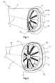
- Fig. 1 shows a fuselage 10 comprising a fuselage section 11 with an inner surface 12 having a non-circular contour with respect to a cross-sectional view of the fuselage section 11.
- the cross-sectional view may be based on a viewing direction which is parallel to a longitudinal axis 15 of the fuselage 10 or of the fuselage section 11.
- the fuselage 10 further comprises a pressure bulkhead 13 which may be a rear pressure bulkhead of an aircraft.
- the pressure bulkhead 13 may comprise an inner surface 31.
- the pressure bulkhead 13 may be integrated into the fuselage section 11 such that a virtual intersection line between a spherical surface 30 of the pressure bulkhead 13 and the inner surface 12 of the fuselage section is provided.
- the spherical surface 30 may be a virtual extension 32 of the inner surface 31 of the pressure bulkhead 13 which intersects the inner surface 12 of the fuselage section 11 and in this manner forms an intersection line 14 between the extended spherical surface 30 and the inner surface 12 of the fuselage section 11.
- the spherical surface 30 which extends the inner surface 31 of the pressure bulkhead may be a virtual spherical surface which corresponds to or lies in the inner surface 31 of the spherical pressure bulkhead.
- the intersection line 14 may be a closed curve which is arranged around the longitudinal axis 15 of the fuselage section 11.
- the virtual intersection line 14 may be a three-dimensional curve extending on the inner surface 12 of the fuselage section 11.
- the pressure bulkhead 13 may extend to the intersection line 14 such that the pressure bulkhead 13 is in contact with the inner surface 12 of the fuselage section 11.
- the pressure bulkhead 13 may also extend to the intersection line 14 such that the pressure bulkhead 13 is not in direct contact to the inner surface 12 of the fuselage section 11.
- a gap between an outer edge of the pressure bulkhead 13 and the inner surface 12 of the fuselage section 11 is provided, wherein the gap comprises a constant distance and extends along the intersection line 14.
- the outer edge of the pressure bulkhead 13 and the virtual intersection line 14 are parallel curves with a predetermined offset which offset may be defined as the distance or gap between the outer edge of the pressure bulkhead 13 and the inner surface 12 of the fuselage section 11.
- Fig. 2 shows a perspective view of a fuselage section 11 and an integrated pressure bulkhead 13 which is attached to an inner surface 12 of the fuselage section 11.
- the pressure bulkhead 13 may be attached to the inner surface 12 by means of an attachment unit 20, which attachment unit 20 may comprise a profile 21 and/or other profiles 25.
- the profile 21 attaches the pressure bulkhead 13 to the inner surface 12 of the fuselage section 11 along the intersection line 14, which intersection line 14 is a virtual three-dimensional curve which is provided by an intersection between an extended inner surface 30 of the pressure bulkhead 13 and the inner surface 12 of the fuselage section 11 as shown in Fig. 1 . Since the profile 21 extends along the intersection line 14, the profile 21 also extends on the inner surface 12 of the fuselage section 11.
- the profile 21, attaches the pressure bulkhead 13 to the inner surface 12 of the fuselage section 11 such that a pressure equalization between the pressurized cabin area and a non-pressurized outer area of the fuselage section 11 is not possible.
- the pressure bulkhead 13 is adapted to separate the pressurized cabin area from the non-pressurized outer area of the fuselage section 11. Therefore, the pressure bulkhead 13 is adapted to transmit pressure loads acting on an outer surface of the pressure bulkhead 13, which is not shown in Fig. 2 , into the fuselage section 11.
- the pressure bulkhead 13 may therefore comprise stiffening units 19 having elongated shapes.
- the elongated stiffening units 19 may be radially arranged around the longitudinal axis 15 of the fuselage section 11.
- the pressure bulkhead 13 may thus be a shell-like structural component with an inner surface 31 on which the stiffening units 19 are located.
- the pressure bulkhead 13 is manufactured from one piece which extends to the inner surface 12 of the fuselage section 11 such that no additional parts are necessary to fill a gap between an outer edge of the pressure bulkhead 11 and the inner surface 12 of the fuselage section 11.
- a small gap with a constant thickness is located between the outer edge of the pressure bulkhead 13 and the inner surface 12 of the fuselage section 11. This gap is defined by a constant thickness which is measured perpendicularly to the inner surface 12 of the fuselage section 11 and indicates the distance between the outer edge of the pressure bulkhead 13 and the inner surface 12 of the fuselage section 11.
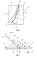
- FIG. 3 shows a detailed view of an attachment unit 20 for attaching the pressure bulkhead 13 to the inner surface 12 of the fuselage section 11.
- the attachment unit 20 comprises a profile 21 which extends along the intersection line 14, which intersection line is a three-dimensional curve.
- the profile 21 comprises a first region 22 and a second region 23, wherein the first region 22 is attached to the inner surface 31 of the pressure bulkhead 13.
- the second region 23 of the profile 21 is attached to the inner surface 12 of the fuselage section 11.
- the profile 21 extends at least along a part of the intersection line 14.
- the attachment unit 20 may further comprise a second profile 25 which also extends along the intersection line 14 and/or the profile 21.
- Fig. 4 shows a cross-sectional view of the profile 21 and a part of the pressure bulkhead 13 as well as a part of the fuselage section 11.
- the first region 22 of the profile 21 is attached via an outer surface 21 a of the profile 21 to the inner surface 31 of the pressure bulkhead 13.
- the profile 21 may further be attached to the fuselage section 11, in particular to the inner surface 12 of the fuselage section 11 by means of the outer surface 12a of the second region 23 of the profile 21.
- the profile 21 may be an L-profile, which L-profile comprises a first flange and a second flange wherein the first region 22 represents the first flange and the second region 23 represents the second flange. Both flanges of the profile 21 enclose an angle ⁇ .
- the angle ⁇ is substantially the angle under which the extended spherical surface 30 of the pressure bulkhead 13 intersects the inner surface 12 of the fuselage section 11.
- the extended spherical inner surface 30 of the pressure bulkhead 13, in particular the inner surface 31 of the pressure bulkhead 13, is indicated by a dashed line in Fig. 4 .
- a non-circular line 17 along which the outer edge 16 of the pressure bulkhead 13 extends or is attached to the inner surface 12 of the fuselage section may have a constant distance to the intersection line 14. However, both lines 14, 17 may extend parallel to each other around the longitudinal axis 15 of the fuselage section 11.
- the profile 12 may comprise an inner surface 21b such that for a person looking from inside the pressurized cabin area, the intersection line 14 is covered by the profile 21.
- an outer edge 16 of the pressure bulkhead 13 may have the distance 18 to the intersection line 14 which is constant along the intersection line 14 when extending along the inner surface 12 of the fuselage section 11.
- the intersection line 14 may be a three-dimensional line which extends around the longitudinal axis 15 of the fuselage section on the inner surface 12 of the fuselage section 11.
- the profile 21 may be attached to the fuselage section 11 by means of the second region 23 and by providing rivets, bolts or screw joints.
- the second region 22 of the profile 21 may be attached to the pressure bulkhead 13 by means of rivets, bolts or screw joints.
- the connecting means like for example rivets, screws or bolts are not shown in Fig. 4 .
- the outer edge 16 of the pressure bulkhead 13 may describe a line or curve which extends along the intersection line 14 at the predetermined distance 18 and therefore is a parallel curve to the intersection line 14.
- the offset between the line or curve describing the outer edge 16 of the pressure bulkhead 13 may be an offset curve with respect to the intersection line 14 extending along the outer edge 16 of the pressure bulkhead 13.
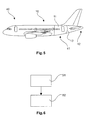
- Fig. 5 shows an aircraft 40 with a fuselage 10, wherein the fuselage 10 comprises a fuselage section 11 and the pressure bulkhead 13.
- the pressure bulkhead 13 is adapted to separate a pressurized cabin area 41 and a non-pressurized outer area 42 of the aircraft 40. Therefore, the pressure bulkhead 13 and/or the attachment unit 20 may further comprise sealings such that a pressure equalization between the pressurized area 41 and the non-pressurized area 42 through the pressure bulkhead can be prevented.
- Fig. 6 shows a flow diagram of a method for manufacturing a fuselage.
- a fuselage section 11 with an inner surface 12 having a non-circular contour is provided in a step S1 of the method.
- a spherical pressure bulkhead 13 with an outer edge 16 is provided in another step S2.
- the outer edge 16 of the spherical pressure bulkhead 13 is attached to the inner surface 12 of the fuselage section 11 and extends along a line, which is non-circular.
- the line 17 is a three-dimensional curve extending parallel to the inner surface 12 of the fuselage section 11.
Landscapes
- Engineering & Computer Science (AREA)
- Mechanical Engineering (AREA)
- Aviation & Aerospace Engineering (AREA)
- Filling Or Discharging Of Gas Storage Vessels (AREA)
Abstract
Description
- The invention generally relates the manufacturing of fuselages for vehicles. In particular, the invention relates to a fuselage, an aircraft comprising a fuselage and a method for manufacturing a fuselage.
- In modem aircraft, pressurized cabin areas are separated from non-pressurized cabin areas by means of so-called pressure bulkheads. The pressure bulkhead comprises a spherical shape in order to effectively transmit pressure loads which are due to the pressure difference between the pressurized cabin area and the non-pressurized outer area of the aircraft. The integration of such a pressure bulkhead requires also an installation of several attachment parts by which the pressure bulkhead is attached to the fuselage of the aircraft. Therefore, several parts are required which are necessary to provide the required stability for transmitting the pressure loads into the primary structure of the aircraft, e.g. the fuselage. Furthermore, since the fuselage section has a non-circular shape and the pressure bulkhead has a spherical shape, the gap between the pressure bulkhead and the non-circular fuselage section has to be closed by special formed parts.
-
US 8 596 578 B2 describes a pressure bulkhead for a fuselage of an aircraft which is configured for bounding a fuselage interior relative to an external environment. The pressure bulkhead includes a flat skin configured to span a cross-section of the fuselage and having a cavity disposed at a core region of the skin. The core region is radially bounded by a ring element. -
US 8 939 404 B2 describes a pressure fuselage of an aircraft, which fuselage in longitudinal direction comprises several fuselage sections, wherein at least one rear dome-shaped pressure bulkhead is provided to form an aircraft-internal pressurized region, with a ring-shaped frame element profile being provided for radially outward attachment of said dome-shaped pressure bulkhead to at least one fuselage section. - It is an object of the present invention to reduce the number of required parts for manufacturing a fuselage section.
- This object can be achieved by the subject-matter of the independent claims. Further exemplary embodiments are evident from the dependent claims and the following description.
- According to an aspect of the present invention, a fuselage is provided. The fuselage comprises a fuselage section with an inner surface having a non-circular contour and a pressure bulkhead, e.g. a spherical pressure bulkhead, with an outer edge. The outer edge of the spherical pressure bulkhead is attached to the inner surface of the fuselage section and extends along a line, which is non-circular. The line is a three-dimensional curve extending parallel to the inner surface of the fuselage section. The line may also be called non-circular line in the following.
- The outer edge may limit the (spherical) extension of the pressure bulkhead. In other words, the pressure bulkhead may have a completely spherical shape which is limited by the outer edge. Therein, the outer edge may be non-circular in a cross sectional view since the outer edge extends along the line which itself is non-circular. For example, the line extends parallel to the outer edge of the pressure bulkhead. However, the line may also be a line defining the outer edge of the pressure bulkhead. Therefore, the line and/or the outer edge of the pressure bulkhead may extend at a constant distance to the inner surface of the fuselage section. The line may be parallel to a virtual intersection line which will be described in the following.
- In other words, the spherical pressure bulkhead is attached to the inner surface of the fuselage section along or parallel to the intersection line of a spherical surface having a region which corresponds to or lies in an inner surface of the spherical pressure bulkhead and a second surface having a region which corresponds to or lies in the inner surface of the fuselage section. It is possible that the line along which the non-circular outer edge of the pressure bulkhead extends is the intersection line, in particular if there is no distance between the outer edge of the pressure bulkhead and the inner surface of the fuselage section. However, there may be a constant distance between the outer edge of the pressure bulkhead and the inner surface of the fuselage section and therefore also between the non-circular line and the virtual intersection line.
- In this manner, the pressure bulkhead can be adapted in its shape such that the pressure bulkhead fits into the fuselage section which, in a cross-sectional view, has a non-circular contour. In particular, the inner surface of the fuselage section has a non-circular contour in a cross-sectional view, e.g. when looking into a longitudinal direction of the fuselage or fuselage section. The pressure bulkhead may be in direct contact to the inner surface of the fuselage section. However, it may also be possible that the pressure bulkhead is attached to the inner surface of the fuselage section while providing a certain distance between the inner surface of the fuselage section and an outer edge of the pressure bulkhead. The virtual intersection line may be defined as a line or curve which extends on the inner surface of the fuselage section and which is generated by intersecting an extended surface of the pressure bulkhead with the inner surface of the fuselage section. In other words, the intersection line is provided by an intersection of a spherical surface which may also be a virtual surface and the inner surface of the fuselage section. A part of this spherical surface may define an inner surface of the spherical pressure bulkhead. Analogously, the part of the second surface may be defined by the inner surface of the fuselage section. The inner surface of the fuselage section may be an inner surface of a skin of the fuselage section, for example of an outer skin of an aircraft.
- The virtual intersection line may be imagined as a line which is generated by extending the inner surface of the spherical pressure bulkhead beyond an outer edge of the spherical pressure bulkhead such that the extension of the inner surface of the spherical pressure bulkhead intersects the inner surface of the fuselage section at the intersection line. Therein, both inner surface of the spherical pressure bulkhead and the extension of the inner surface of the pressure bulkhead may comprise a spherical form or shape. The intersection line as well as the spherical surface and the second surface may be virtual geometrical parts which help to describe the arrangement of the pressure bulkhead with respect to the fuselage section. The pressure bulkhead may be directly attached to the fuselage section at the intersection line. It may also be possible that the pressure bulkhead may be attached to the fuselage section, e.g. to the inner surface of the fuselage section by means of an attachment unit. However, the attachment of the pressure bulkhead is located at the non-circular line or at the virtual intersection line, which itself is defined as an intersection line between the virtually extended inner surface of the spherical pressure bulkhead and the inner surface of the fuselage section. The pressure bulkhead which is attached to the inner surface of the fuselage section along the non-circular line or the virtual intersection line may have a completely spherical shape. However, in a cross-sectional view or in a front view of the fuselage section, the pressure bulkhead may have a non-circular outer edge which follows or extends parallel to the non-circular contour of the inner surface of the fuselage section. This aspect will be explained in more detail in the description of the figures.
- The fuselage may be a vehicle fuselage. In particular, the fuselage may be an aircraft fuselage, wherein the pressure bulkhead which is comprised by the fuselage may separate a cabin area of the aircraft from an outer area of the aircraft. The pressure bulkhead may be stiffened by stiffening units such that pressure loads acting on the pressure bulkhead can be transferred through the pressure bulkhead and then into the fuselage section. The pressure bulkhead may be adapted to transmit pressure loads acting on a surface of the pressure bulkhead into the fuselage structure.
- The spherical pressure bulkhead may extend to the inner surface of the fuselage section such that no additional parts are necessary to close a gap between the outer edge of the pressure bulkhead and the inner surface of the fuselage section. However, it may also be possible that a small gap between the outer edge of the pressure bulkhead, e.g. the non-circular line, and the inner surface of the fuselage section occurs, wherein the gap extends along the intersection line and wherein the gap has a constant thickness. In other words, the gap may be defined by a distance between the outer edge of the pressure bulkhead or the non-circular line and the inner surface of the fuselage section, which distance is constant along the intersection line. The distance may be measured in a perpendicular direction to the inner surface of the fuselage section or to a longitudinal axis of the fuselage section. Therefore, the outer edge of the pressure bulkhead may be defined by the non-circular line which extends parallel to the virtual intersection line. This means that the line defining the outer edge of the pressure bulkhead and the virtual intersection line are parallel lines or curves which may have a substantially constant offset. However, the intersection line may extend on the inner surface of the fuselage section and/or the outer edge of the pressure bulkhead may extend along the virtual intersection line at a predetermined offset which is constant along the intersection line.
- Furthermore, the non-circular line is a three-dimensional curve extending parallel to the inner surface of the fuselage section. The non-circular line representing the outer edge of the pressure bulkhead is a three-dimensional curve since the pressure bulkhead which may have a completely spherical shape extends to the outer edge which itself is non-circular. A spherical body which extends to its outer edge such that the outer edge is non-circular in a cross sectional view can only describe a line or curve which is three-dimensional. Hence, it is not possible that the non-circular line only extends in a virtual plane, like a two-dimensional line for example. This means that at certain locations the non-circular line is deflected from the virtual plane which is perpendicular to the longitudinal axis of the fuselage section. In other words, the non-circular line comprises a component which is deflected from the virtual plane into the longitudinal direction of the fuselage section. The non-circular line may extend parallel or on the inner surface of the fuselage section.
- Moreover, the virtual intersection line may also be three-dimensional because it is defined by an intersection between a spherical element, e.g. the spherical pressure bulkhead, and a longitudinal fuselage section which may have an inner surface with a non-circular contour in a cross-sectional view. For example, the fuselage section is a longitudinally extended body and the pressure bulkhead is a spherical body, both bodies being arranged such that the inner surface of the fuselage section and an extended virtual surface of the pressure bulkhead intersect at the intersection line. Therefore, the intersection line may be a three-dimensional line or curve.
- According to another embodiment of the invention, a distance between the outer edge of the pressure bulkhead and the inner surface of the fuselage section is constant.
- In other words, the non-circular outer edge, e.g. the non-circular line, is aligned with the non-circular contour of the inner surface of the fuselage section and/or the virtual intersection line. The outer edge of the pressure bulkhead may therefore have a constant distance to the inner surface of the fuselage section wherein the constant distance may be measured between the virtual intersection line and the outer edge of the pressure bulkhead perpendicular to the longitudinal axis of the fuselage section. The outer edge of the pressure bulkhead may define a curve, e.g. the non-circular line which extends along the intersection line in a parallel manner. In other words, the line defining the outer edge of the pressure bulkhead and the intersection line are parallel curves having a substantially constant predetermined offset or distance. Therein, the virtual intersection line extends on the inner surface of the fuselage section. However, it may also be possible that the outer edge of the pressure bulkhead, e.g. the line defining the outer edge of the pressure bulkhead, is in direct contact to the inner surface of the fuselage section and/or the second non-circular edge. It should be mentioned that the pressure bulkhead may be manufactured as one piece.
- According to another embodiment of the invention, the line forms a closed curve which encloses a longitudinal axis of the fuselage section.
- In other words, the non-circular line may be three-dimensional curve which extends around the longitudinal axis of the fuselage section. Moreover, the non-circular line may extend on or parallel to the inner surface of the fuselage section. The inner surface of the fuselage section may be defined by an extruded curve wherein the curve may be extruded along the longitudinal axis of the fuselage section and wherein the extruded curve may provide a surface defining the inner surface of the fuselage section. The extruded curve may be a closed curve enclosing the longitudinal axis of the fuselage section, thereby forming a so called loft when the curve becomes extruded.
- Furthermore, the virtual intersection line which may be three-dimensional curve which extends around the longitudinal axis of the fuselage section. Moreover, the intersection line may extend on the inner surface of the fuselage section. However, the virtual intersection line may be generated by an intersection between a spherically curved surface, e.g. the virtually extended spherical inner surface of the pressure bulkhead and the inner surface of the fuselage section. The inner surface of the fuselage section may be defined by an extruded curve wherein the curve may be extruded along the longitudinal axis of the fuselage section and wherein the extruded curve may provide a surface defining the inner surface of the fuselage section. The extruded curve may be a closed curve enclosing the longitudinal axis of the fuselage section, thereby forming a so called loft when the curve becomes extruded.
- According to another embodiment of the invention, the pressure bulkhead forms a barrier between a pressurized cabin area and a non-pressurized outer area of the fuselage section.
- In particular, the pressure bulkhead may be a rear pressure bulkhead in a fuselage section of an aircraft which separates the pressurized cabin area and the non-pressurized outer area of the fuselage section, for example during flight. Therefore, it is possible that the pressure bulkhead is adapted to transmit pressure loads acting on the pressure bulkhead into the fuselage section and therefore into the fuselage, e.g. into a primary structure of an aircraft. The pressure bulkhead may comprise a pressure optimized spherical shape. However, it may be possible that the pressure loads are transferred into the fuselage section at the virtual intersection line which three-dimensionally extends on the inner surface of the fuselage section.
- According to another embodiment of the invention, the pressure bulkhead comprises a shell-like structure in the form of a spherical dome.
- In other words, the pressure bulkhead may have the shape of a spherical calotte or a spherical cap. However, the pressure bulkhead is adapted to effectively transmit pressure loads into the fuselage section. The pressure bulkhead may have a spherical shape, but a non-circular outer edge in a cross sectional view or in a front view.
- According to yet another embodiment of the invention, the fuselage further comprises an attachment unit for attaching the pressure bulkhead to the inner surface of the fuselage section. Therein, the attachment unit is located in a region of the outer edge of the pressure bulkhead.
- By means of the attachment unit, it is possible that the pressure loads acting on the pressure bulkhead, for example on a surface of the pressure bulkhead, can be effectively transmitted into the fuselage section. The pressure bulkhead may be attached to the inner surface of the fuselage section via the attachment unit such that the pressure bulkhead is not in direct contact the inner surface of the fuselage section. In particular, there may be a constant distance between the non-circular outer edge of the pressure bulkhead and the inner surface of the fuselage section along the intersection line or along the non-circular line. The distance therefore generates a gap between the outer edge of the pressure bulkhead and the inner surface of the fuselage section, which gap can be closed by at least a part of the attachment unit. In other words, the attachment unit may fill or bridge the gap which is defined by the constant distance and therefore connects the pressure bulkhead to the inner surface of the fuselage section. However, it is also possible that the outer edge of the pressure bulkhead is in direct contact to the inner surface of the fuselage section while the attachment unit provides a fixation of the pressure bulkhead within the fuselage section. In this case, the non-circular line may lie in the virtual intersection line.
- According to another embodiment of the invention, the attachment unit comprises a profile, which extends along at least a part of a virtual intersection line and/or the non-circular line along which the outer edge of the spherical pressure bulkhead is attached to the inner surface of the fuselage section.
- The virtual intersection line may be the intersection line as described above, e.g, the intersection line generated by an intersection of an extended inner surface of the pressure bulkhead and the inner surface of the fuselage section. The profile may be an elongated profile which follows or extends parallel to the virtual intersection line and/or the non-circular line defining the outer edge of the pressure bulkhead, for example at a predetermined distance. The profile may be adapted to attach the pressure bulkhead to the inner surface of the fuselage section. The fact that the profile only extends along at least a part of the line and/or virtual intersection line, facilitates the integration or the attachment of the profile to the fuselage. In other words, the pressure bulkhead may be attached to the inner surface of the fuselage section step by step which means that a plurality of profiles may be attached one after another. It should be mentioned that the attachment unit comprises a profile in a cross-sectional view. The profile extends along at least a part of the line and/or virtual intersection line means that the cross section of the profile remains constant when extruding along or into the direction of the virtual intersection line or the non-circular line.
- According to another embodiment of the invention, the profile comprises a constant cross-section along the part of the virtual intersection line or the non-circular line describing the outer edge of the pressure bulkhead. The profile may also be a curved part because it extends along the three-dimensional intersection line.
- For example, the profile has a constant width, a constant height, etc. In other words, the edges of the profile may have a constant distance from each other while the profile is extruded or extends along the part of the virtual intersection line.
- According to another embodiment of the invention, the profile comprises an outer surface and an inner surface. The outer surface of the profile is attached to the inner surface of the fuselage section and to an inner surface of the pressure bulkhead.
- For a person looking from inside the fuselage section, the intersection line may be covered by the profile such that the person looking from inside the fuselage section only sees the inner surface of the profile. This is due to the fact that the outer surface is attached to the pressure bulkhead and to the inner surface of the fuselage section. This also provides an easier access within the fuselage section when attaching the pressure bulkhead to the fuselage section. For example, the profile is attached to the pressure bulkhead and/or to the fuselage section by means of screws, bolts or rivets.
- According to yet another embodiment of the invention, the profile comprises a first region and a second region adjacent to the first region both forming an obtuse angle α. Therein, the first region is attached to the pressure bulkhead and the second region is attached to the inner surface of the fuselage section.
- For example, the profile comprises the form of an L-profile, wherein the flanges of the L-profile enclose an obtuse angle. The first region may be defined by the first flange and the second region may be defined by the second flange of the L-profile such that the first flange of the L-profile is attached to the pressure bulkhead and the second flange of the L-profile is attached to the inner surface of the fuselage section. This L-profile may extend along or parallel to the intersection line. The obtuse angle is a result of the fact that the spherical pressure bulkhead ends on the inner surface of the fuselage section under the obtuse angle α which requires the integration of the profile in the form of a connection angle connecting the pressure bulkhead to the inner surface of the fuselage section.
- According to another embodiment of the invention, the fuselage further comprises a plurality of profiles, wherein each of the profiles extends along at least a part of the virtual intersection line or the non-circular line such that the plurality of profiles together form a frame which is aligned with the virtual intersection line.
- In this manner, the pressure bulkhead may be attached to the inner surface of the fuselage section along the whole intersection line and therefore along the whole inner surface of the fuselage section, thus providing an effective means for transmitting the loads acting on the pressure bulkhead into the fuselage section. In other words, a frame is provided around the longitudinal axis of the fuselage section or the fuselage. The frame may be an extruded profile along and/or parallel to the intersection line and therefore also along and/or parallel to the inner surface of the fuselage section. The frame may further provide a stiffening of the fuselage section in a region of the intersection line. The usage of the plurality of profiles provides an easier integration of the attachment unit, e.g. the plurality of profiles may be integrated into the fuselage section step by step, in order to provide an attachment means for attaching the pressure bulkhead to the inner surface of the fuselage section. The plurality of profiles may therefore be attached to the pressure bulkhead in a region of the outer edge or the non circular line of the pressure bulkhead.
- According to another embodiment of the invention, the pressure bulkhead is manufactured of a material selected from a group, the group comprising a composite material, a fiber composite material and a carbon fiber reinforced plastic.
- Using composite materials, provides the opportunity to reduce weight of the pressure bulkhead which is important when using the pressure bulkhead for aircraft applications. The pressure bulkhead may be stiffened by stiffening units which may also be manufactured from a material selected from the group comprising a composite material, a fiber composite material and a carbon fiber-reinforced plastic. The pressure bulkhead, which may be a rear pressure bulkhead of an aircraft, is manufactured from one piece.
- According to another embodiment of the invention, the pressure bulkhead comprises a spherical shape.
- In particular, the pressure bulkhead may comprise a completely spherical shape. In this manner, pressure loads acting on the pressure bulkhead can be effectively transmitted into the fuselage structure, for example into the fuselage structure of an aircraft.
- According to an aspect of the present invention, an aircraft comprising a fuselage is provided. The fuselage may comprise the features as described above.
- For example, the pressure bulkhead of the fuselage may be a rear pressure bulkhead of the aircraft which separates the pressurized cabin area and the non-pressurized outer area of the aircraft, e.g. of the fuselage of the aircraft.
- According to another aspect of the present invention, a method for manufacturing a fuselage is provided. In a step of the method, a fuselage section with an inner surface having a non-circular contour is provided. In another step of the method, a spherical pressure bulkhead with an outer edge is provided. The outer edge of the spherical pressure bulkhead is attached to the inner surface of the fuselage section and extends along a line, which is non-circular. The line is a three-dimensional curve extending parallel to the inner surface of the fuselage section. The steps may comprise the features as described with reference to the fuselage above.
- The method may comprise further steps, for example the step of providing a constant distance between an outer edge of the pressure bulkhead and the inner surface of the fuselage section. In another step, the pressure bulkhead may be attached to the inner surface of the fuselage section by means of an attachment unit which attachment unit comprises a profile extending along the outer edge or the virtual intersection line.
-
- Fig. 1
- shows a perspective view of an intersection of an inner surface of the fuselage section and a surface of a pressure bulkhead according to an embodiment of the invention.
- Fig. 2
- shows a perspective view of a pressure bulkhead which is attached to an inner surface of the fuselage section by means of an attachment unit according to an embodiment of the invention.
- Fig. 3
- shows a detailed view of an attachment unit for attaching a pressure bulkhead to an inner surface of a fuselage section according to an embodiment of the invention.
- Fig. 4
- shows a cross-sectional view of an attachment unit comprising a profile for attaching a pressure bulkhead to an inner surface of a fuselage section according to an embodiment of the invention.
- Fig. 5
- shows an aircraft with a fuselage section and a pressure bulkhead according to an embodiment of the invention.
- Fig. 6
- shows a flow diagram of a method for manufacturing a fuselage according to an embodiment of the invention.
- The items shown in the figures are not drawn to scale.
-
Fig. 1 shows afuselage 10 comprising afuselage section 11 with aninner surface 12 having a non-circular contour with respect to a cross-sectional view of thefuselage section 11. The cross-sectional view may be based on a viewing direction which is parallel to alongitudinal axis 15 of thefuselage 10 or of thefuselage section 11. Thefuselage 10 further comprises apressure bulkhead 13 which may be a rear pressure bulkhead of an aircraft. Thepressure bulkhead 13 may comprise aninner surface 31. Thepressure bulkhead 13 may be integrated into thefuselage section 11 such that a virtual intersection line between aspherical surface 30 of thepressure bulkhead 13 and theinner surface 12 of the fuselage section is provided. Thespherical surface 30 may be avirtual extension 32 of theinner surface 31 of thepressure bulkhead 13 which intersects theinner surface 12 of thefuselage section 11 and in this manner forms anintersection line 14 between the extendedspherical surface 30 and theinner surface 12 of thefuselage section 11. Thespherical surface 30 which extends theinner surface 31 of the pressure bulkhead may be a virtual spherical surface which corresponds to or lies in theinner surface 31 of the spherical pressure bulkhead. This virtualspherical surface 30, which is an extension of theinner surface 31 of thepressure bulkhead 13, intersects theinner surface 12 of thefuselage section 11 at theintersection line 14. Theintersection line 14 may be a closed curve which is arranged around thelongitudinal axis 15 of thefuselage section 11. Thevirtual intersection line 14 may be a three-dimensional curve extending on theinner surface 12 of thefuselage section 11. However, thepressure bulkhead 13 may extend to theintersection line 14 such that thepressure bulkhead 13 is in contact with theinner surface 12 of thefuselage section 11. However, thepressure bulkhead 13 may also extend to theintersection line 14 such that thepressure bulkhead 13 is not in direct contact to theinner surface 12 of thefuselage section 11. In particular, a gap between an outer edge of thepressure bulkhead 13 and theinner surface 12 of thefuselage section 11 is provided, wherein the gap comprises a constant distance and extends along theintersection line 14. In other words, the outer edge of thepressure bulkhead 13 and thevirtual intersection line 14 are parallel curves with a predetermined offset which offset may be defined as the distance or gap between the outer edge of thepressure bulkhead 13 and theinner surface 12 of thefuselage section 11. -
Fig. 2 shows a perspective view of afuselage section 11 and anintegrated pressure bulkhead 13 which is attached to aninner surface 12 of thefuselage section 11. Thepressure bulkhead 13 may be attached to theinner surface 12 by means of anattachment unit 20, whichattachment unit 20 may comprise aprofile 21 and/orother profiles 25. Theprofile 21 attaches thepressure bulkhead 13 to theinner surface 12 of thefuselage section 11 along theintersection line 14, whichintersection line 14 is a virtual three-dimensional curve which is provided by an intersection between an extendedinner surface 30 of thepressure bulkhead 13 and theinner surface 12 of thefuselage section 11 as shown inFig. 1 . Since theprofile 21 extends along theintersection line 14, theprofile 21 also extends on theinner surface 12 of thefuselage section 11. Theattachment unit 20, e.g. theprofile 21, attaches thepressure bulkhead 13 to theinner surface 12 of thefuselage section 11 such that a pressure equalization between the pressurized cabin area and a non-pressurized outer area of thefuselage section 11 is not possible. This is advantageous because thepressure bulkhead 13 is adapted to separate the pressurized cabin area from the non-pressurized outer area of thefuselage section 11. Therefore, thepressure bulkhead 13 is adapted to transmit pressure loads acting on an outer surface of thepressure bulkhead 13, which is not shown inFig. 2 , into thefuselage section 11. Thepressure bulkhead 13 may therefore comprise stiffeningunits 19 having elongated shapes. Theelongated stiffening units 19 may be radially arranged around thelongitudinal axis 15 of thefuselage section 11. Thepressure bulkhead 13 may thus be a shell-like structural component with aninner surface 31 on which thestiffening units 19 are located. For example, thepressure bulkhead 13 is manufactured from one piece which extends to theinner surface 12 of thefuselage section 11 such that no additional parts are necessary to fill a gap between an outer edge of thepressure bulkhead 11 and theinner surface 12 of thefuselage section 11. However, it is possible that a small gap with a constant thickness is located between the outer edge of thepressure bulkhead 13 and theinner surface 12 of thefuselage section 11. This gap is defined by a constant thickness which is measured perpendicularly to theinner surface 12 of thefuselage section 11 and indicates the distance between the outer edge of thepressure bulkhead 13 and theinner surface 12 of thefuselage section 11. This distance may be constant along the outer edge of thepressure bulkhead 13 and/or along theintersection line 14 which extends on theinner surface 12 of thefuselage section 11.Fig. 3 shows a detailed view of anattachment unit 20 for attaching thepressure bulkhead 13 to theinner surface 12 of thefuselage section 11. Theattachment unit 20 comprises aprofile 21 which extends along theintersection line 14, which intersection line is a three-dimensional curve. Theprofile 21 comprises afirst region 22 and asecond region 23, wherein thefirst region 22 is attached to theinner surface 31 of thepressure bulkhead 13. Thesecond region 23 of theprofile 21 is attached to theinner surface 12 of thefuselage section 11. Theprofile 21 extends at least along a part of theintersection line 14. Theattachment unit 20 may further comprise asecond profile 25 which also extends along theintersection line 14 and/or theprofile 21. -
Fig. 4 shows a cross-sectional view of theprofile 21 and a part of thepressure bulkhead 13 as well as a part of thefuselage section 11. Thefirst region 22 of theprofile 21 is attached via anouter surface 21 a of theprofile 21 to theinner surface 31 of thepressure bulkhead 13. Theprofile 21 may further be attached to thefuselage section 11, in particular to theinner surface 12 of thefuselage section 11 by means of the outer surface 12a of thesecond region 23 of theprofile 21. Theprofile 21 may be an L-profile, which L-profile comprises a first flange and a second flange wherein thefirst region 22 represents the first flange and thesecond region 23 represents the second flange. Both flanges of theprofile 21 enclose an angle α. The angle α is substantially the angle under which the extendedspherical surface 30 of thepressure bulkhead 13 intersects theinner surface 12 of thefuselage section 11. The extended sphericalinner surface 30 of thepressure bulkhead 13, in particular theinner surface 31 of thepressure bulkhead 13, is indicated by a dashed line inFig. 4 . Theintersection line 14 between the extended sphericalinner surface 30 of thepressure bulkhead 13, which extended sphericalinner surface 30 may be a virtual surface, and theinner surface 12 of thefuselage section 11 may be located on theinner surface 21 of thefuselage section 11. Anon-circular line 17 along which theouter edge 16 of thepressure bulkhead 13 extends or is attached to theinner surface 12 of the fuselage section may have a constant distance to theintersection line 14. However, bothlines longitudinal axis 15 of thefuselage section 11. - The
profile 12 may comprise aninner surface 21b such that for a person looking from inside the pressurized cabin area, theintersection line 14 is covered by theprofile 21. However, anouter edge 16 of thepressure bulkhead 13 may have thedistance 18 to theintersection line 14 which is constant along theintersection line 14 when extending along theinner surface 12 of thefuselage section 11. Theintersection line 14 may be a three-dimensional line which extends around thelongitudinal axis 15 of the fuselage section on theinner surface 12 of thefuselage section 11. Theprofile 21 may be attached to thefuselage section 11 by means of thesecond region 23 and by providing rivets, bolts or screw joints. Analogously, thesecond region 22 of theprofile 21 may be attached to thepressure bulkhead 13 by means of rivets, bolts or screw joints. The connecting means like for example rivets, screws or bolts are not shown inFig. 4 . Theouter edge 16 of thepressure bulkhead 13 may describe a line or curve which extends along theintersection line 14 at thepredetermined distance 18 and therefore is a parallel curve to theintersection line 14. The offset between the line or curve describing theouter edge 16 of thepressure bulkhead 13 may be an offset curve with respect to theintersection line 14 extending along theouter edge 16 of thepressure bulkhead 13. -
Fig. 5 shows anaircraft 40 with afuselage 10, wherein thefuselage 10 comprises afuselage section 11 and thepressure bulkhead 13. Thepressure bulkhead 13 is adapted to separate apressurized cabin area 41 and a non-pressurizedouter area 42 of theaircraft 40. Therefore, thepressure bulkhead 13 and/or theattachment unit 20 may further comprise sealings such that a pressure equalization between thepressurized area 41 and thenon-pressurized area 42 through the pressure bulkhead can be prevented. -
Fig. 6 shows a flow diagram of a method for manufacturing a fuselage. In a step S1 of the method, afuselage section 11 with aninner surface 12 having a non-circular contour is provided. In another step S2, aspherical pressure bulkhead 13 with anouter edge 16 is provided. Theouter edge 16 of thespherical pressure bulkhead 13 is attached to theinner surface 12 of thefuselage section 11 and extends along a line, which is non-circular. Theline 17 is a three-dimensional curve extending parallel to theinner surface 12 of thefuselage section 11. - While the invention has been illustrated and described in detail in the drawings and the foregoing description, such illustration and description are to be considered illustrative and exemplary and not restrictive; the invention is not limited to the disclosed embodiments. Other variations to the disclosed embodiments can be understood and effected by those skilled in the art and practicing the claimed invention, from a study of the drawings, the disclosure, and the appended clams. In the claims the term "comprising" does not exclude other elements, and the indefinite article "a" or "an" does not exclude a plurality. The mere fact that certain measures are recited in mutually different dependant claims does not indicate that a combination of these measures cannot be used to advantage. Any reference signs in the claims should not be construed as limiting the scope of protection.
Claims (15)
- Fuselage (10), comprising:a fuselage section (11) with an inner surface (12) having a non-circular contour;a pressure bulkhead (13) with an outer edge (16);wherein the outer edge (16) of the pressure bulkhead (13) is attached to the inner surface (12) of the fuselage section (11) and extends along a line (17), which is non-circular; andwherein the line (17) is a three-dimensional curve extending parallel to the inner surface (12) of the fuselage section (11).
- Fuselage (10) according to claim 1,
wherein a distance between the outer edge (16) of the pressure bulkhead (13) and the inner surface (12) of the fuselage section (11) is constant. - Fuselage (10) according to one of the preceding claims,
wherein the line (17) forms a closed curve which encloses a longitudinal axis (15) of the fuselage section (11). - Fuselage (10) according to one of the preceding claims,
wherein the pressure bulkhead (13) forms a barrier between a pressurized cabin area and a non-pressurized outer area of the fuselage section (11). - Fuselage (10) according to one of the preceding claims,
wherein the pressure bulkhead (13) comprises a shell-like structure in the form of a dome. - Fuselage (10) according to one of the preceding claims, further comprising:an attachment unit (20) for attaching the pressure bulkhead (13) to the inner surface (12) of the fuselage section (11);wherein the attachment unit (20) is located in a region of the outer edge (16) of the pressure bulkhead (13).
- Fuselage (10) according to claim 6,
wherein the attachment unit (20) comprises a profile (21), which extends along at least a part of a virtual intersection line (14) and/or the non-circular line (17) along which the outer edge (16) of the pressure bulkhead (13) is attached to the inner surface (12) of the fuselage section. - Fuselage (10) according to claim 7,
wherein the profile (21) comprises a constant cross section along the part of the virtual intersection line (14) and or the non-circular line (17). - Fuselage (10) according to one of claims 7 or 8,
wherein the profile (21) comprises an outer surface (21a) and an inner surface (21b),
wherein the outer surface (21a) of the profile (21) is attached to the inner surface (12) of the fuselage section (12) and to an inner surface (31) of the pressure bulkhead (13). - Fuselage (10) according to one of claims 7 to 9,
wherein the profile (21) comprises a first region (22) and a second region (23) adjacent to the first region (22), both forming an obtuse angle α,
wherein the first region (22) is attached to the pressure bulkhead (13) and the second region (23) is attached to the inner surface (12) of the fuselage section. - Fuselage (10) according to one of claims 7 to 10, further comprising:plurality of profiles (21),wherein each of the profiles (21) extends along a part of the virtual intersection line (14) and/or the non-circular line (17) such that the plurality of profiles (21) together forms a frame which is aligned with the virtual intersection line (14) and/or the non-circular line.
- Fuselage (10) according to one of the preceding claims,
wherein the pressure bulkhead (13) is manufactured of a material selected from a group, the group comprising a composite material, a fiber composite material and a carbon fiber-reinforced plastic. - Fuselage (10) according to one of the preceding claims,
wherein the pressure bulkhead (13) comprises a spherical shape. - Aircraft (40), comprising a fuselage (10) according to one of the preceding claims.
- Method for manufacturing a fuselage (10), comprising:providing a fuselage section (11) with an inner surface (12) having a non-circular contour (S1);providing a pressure bulkhead (13) with an outer edge (S2);wherein the outer edge (16) of the pressure bulkhead (13) is attached to the inner surface (12) of the fuselage section (11) and extends along a line (17), which is non-circular; andwherein the line (17) is a three-dimensional curve extending parallel to the inner surface (12) of the fuselage section (11).
Priority Applications (3)
| Application Number | Priority Date | Filing Date | Title |
|---|---|---|---|
| ES15158047T ES2709346T3 (en) | 2015-03-06 | 2015-03-06 | Back pressure bulkhead extended |
| EP15158047.9A EP3064430B1 (en) | 2015-03-06 | 2015-03-06 | Extended rear pressure bulkhead |
| US15/058,524 US10689088B2 (en) | 2015-03-06 | 2016-03-02 | Extended rear pressure bulkhead |
Applications Claiming Priority (1)
| Application Number | Priority Date | Filing Date | Title |
|---|---|---|---|
| EP15158047.9A EP3064430B1 (en) | 2015-03-06 | 2015-03-06 | Extended rear pressure bulkhead |
Publications (2)
| Publication Number | Publication Date |
|---|---|
| EP3064430A1 true EP3064430A1 (en) | 2016-09-07 |
| EP3064430B1 EP3064430B1 (en) | 2018-11-14 |
Family
ID=52629444
Family Applications (1)
| Application Number | Title | Priority Date | Filing Date |
|---|---|---|---|
| EP15158047.9A Not-in-force EP3064430B1 (en) | 2015-03-06 | 2015-03-06 | Extended rear pressure bulkhead |
Country Status (3)
| Country | Link |
|---|---|
| US (1) | US10689088B2 (en) |
| EP (1) | EP3064430B1 (en) |
| ES (1) | ES2709346T3 (en) |
Cited By (2)
| Publication number | Priority date | Publication date | Assignee | Title |
|---|---|---|---|---|
| FR3068002A1 (en) * | 2017-06-23 | 2018-12-28 | Airbus Operations (S.A.S.) | REAR SEALED BOTTOM COMPRISING A COMPOUND GEOMETRY MEMBRANE |
| DE102017219073A1 (en) | 2017-10-25 | 2019-04-25 | Airbus Operations Gmbh | Hull structure for an aircraft and aircraft |
Families Citing this family (3)
| Publication number | Priority date | Publication date | Assignee | Title |
|---|---|---|---|---|
| DE102016002844B3 (en) * | 2016-03-10 | 2017-08-10 | Premium Aerotec Gmbh | Structural component, method for producing a structural component, pressure hull for a vehicle with structural component |
| ES2946516T3 (en) * | 2018-03-02 | 2023-07-20 | Premium Aerotec Gmbh | Pressure bulkhead for an aircraft |
| ES3032500T3 (en) * | 2022-07-13 | 2025-07-21 | Airbus Operations Slu | Pressure bulkhead attachment |
Citations (7)
| Publication number | Priority date | Publication date | Assignee | Title |
|---|---|---|---|---|
| US4712751A (en) * | 1985-07-24 | 1987-12-15 | Messerschmitt-Boelkow-Blohm Gesellschaft Mit Beschraenkter Haftung | Tail end structure for an aircraft fuselage |
| US5062589A (en) * | 1989-02-28 | 1991-11-05 | Dornier Luftfahrt Gmbh | Fiber reinforced pressure bulkhead with integrated frame |
| US5934616A (en) * | 1996-12-14 | 1999-08-10 | Daimlerchrysler Aerospace Airbus Gmbh | Aircraft pressure bulkhead |
| US20090137196A1 (en) * | 2007-11-13 | 2009-05-28 | Eads Deutschland Gmbh | Pressure bulkhead for an aircraft |
| US20130099053A1 (en) * | 2011-10-19 | 2013-04-25 | The Boeing Company | Mid-Wing Multi-Deck Airplane |
| US8596578B2 (en) | 2010-04-30 | 2013-12-03 | Airbus Operations Gmbh | Pressure bulkhead for purposes of arrangement in an aircraft fuselage |
| US8939404B2 (en) | 2009-10-09 | 2015-01-27 | Airbus Operations Gmbh | Pressure fuselage of an aircraft with dome-shaped pressure bulkhead |
Family Cites Families (13)
| Publication number | Priority date | Publication date | Assignee | Title |
|---|---|---|---|---|
| US5778813A (en) * | 1996-11-13 | 1998-07-14 | Fern Investments Limited | Composite steel structural plastic sandwich plate systems |
| AT405813B (en) * | 1997-11-10 | 1999-11-25 | Fischer Adv Components Gmbh | PRESSURE BOARD, IN PARTICULAR FOR AIRCRAFT |
| DE102006029231B4 (en) * | 2006-06-26 | 2013-09-26 | Airbus Operations Gmbh | Pressure bulkhead for a hull for the aerospace industry |
| US20080179459A1 (en) * | 2007-01-30 | 2008-07-31 | Airbus Espana, S.L. | Pressure bulkhead made of composite material for an aircraft |
| DE102007044388B4 (en) * | 2007-09-18 | 2012-08-02 | Airbus Operations Gmbh | Pressure bulkhead and method for dividing an aircraft or spacecraft |
| DE102007052140B4 (en) * | 2007-10-31 | 2012-10-25 | Airbus Operations Gmbh | Structure, in particular hull structure of an aircraft or spacecraft |
| DE102008040213B4 (en) * | 2008-07-07 | 2011-08-25 | Airbus Operations GmbH, 21129 | Method for mounting a dome-shaped pressure bulkhead in a tail section of an aircraft, and device for carrying out the method |
| ES2347122B1 (en) * | 2009-03-31 | 2011-08-11 | Airbus Operations, S.L. | ASSEMBLY STRUCTURE OF THE PRESSURE SOCKET OF AN AIRCRAFT. |
| ES2376098B1 (en) * | 2009-07-24 | 2013-02-04 | Airbus Operations S.L. | PROCESS OF ASSEMBLY OF FUSELAGE SECTIONS OF AN AIRCRAFT. |
| DE102012205633A1 (en) * | 2012-04-05 | 2013-10-10 | Airbus Operations Gmbh | Method and device for joining tolerance-related joining partners |
| DE102012016553A1 (en) * | 2012-08-22 | 2014-02-27 | Airbus Operations Gmbh | Pressure hull of an aircraft comprising a pressure bulkhead |
| US10189578B2 (en) * | 2013-06-12 | 2019-01-29 | The Boeing Company | Self-balancing pressure bulkhead |
| EP3064429A1 (en) * | 2015-03-06 | 2016-09-07 | Airbus Operations GmbH | Pressure bulkhead adapted to non-circular fuselage section |
-
2015
- 2015-03-06 EP EP15158047.9A patent/EP3064430B1/en not_active Not-in-force
- 2015-03-06 ES ES15158047T patent/ES2709346T3/en active Active
-
2016
- 2016-03-02 US US15/058,524 patent/US10689088B2/en active Active
Patent Citations (7)
| Publication number | Priority date | Publication date | Assignee | Title |
|---|---|---|---|---|
| US4712751A (en) * | 1985-07-24 | 1987-12-15 | Messerschmitt-Boelkow-Blohm Gesellschaft Mit Beschraenkter Haftung | Tail end structure for an aircraft fuselage |
| US5062589A (en) * | 1989-02-28 | 1991-11-05 | Dornier Luftfahrt Gmbh | Fiber reinforced pressure bulkhead with integrated frame |
| US5934616A (en) * | 1996-12-14 | 1999-08-10 | Daimlerchrysler Aerospace Airbus Gmbh | Aircraft pressure bulkhead |
| US20090137196A1 (en) * | 2007-11-13 | 2009-05-28 | Eads Deutschland Gmbh | Pressure bulkhead for an aircraft |
| US8939404B2 (en) | 2009-10-09 | 2015-01-27 | Airbus Operations Gmbh | Pressure fuselage of an aircraft with dome-shaped pressure bulkhead |
| US8596578B2 (en) | 2010-04-30 | 2013-12-03 | Airbus Operations Gmbh | Pressure bulkhead for purposes of arrangement in an aircraft fuselage |
| US20130099053A1 (en) * | 2011-10-19 | 2013-04-25 | The Boeing Company | Mid-Wing Multi-Deck Airplane |
Cited By (2)
| Publication number | Priority date | Publication date | Assignee | Title |
|---|---|---|---|---|
| FR3068002A1 (en) * | 2017-06-23 | 2018-12-28 | Airbus Operations (S.A.S.) | REAR SEALED BOTTOM COMPRISING A COMPOUND GEOMETRY MEMBRANE |
| DE102017219073A1 (en) | 2017-10-25 | 2019-04-25 | Airbus Operations Gmbh | Hull structure for an aircraft and aircraft |
Also Published As
| Publication number | Publication date |
|---|---|
| EP3064430B1 (en) | 2018-11-14 |
| ES2709346T3 (en) | 2019-04-16 |
| US10689088B2 (en) | 2020-06-23 |
| US20160257392A1 (en) | 2016-09-08 |
Similar Documents
| Publication | Publication Date | Title |
|---|---|---|
| US10689088B2 (en) | Extended rear pressure bulkhead | |
| JP5416410B2 (en) | Weight-optimized pressurizable aircraft fuselage structure with a near-elliptical cross section | |
| US10604225B2 (en) | Pressure bulkhead adapted to non-circular fuselage section | |
| EP2444315B1 (en) | Metal fittings for engaging the vertical tailplane of an aircraft | |
| US9227375B2 (en) | Process for bonding two parts subjected to tensile forces, bonded parts obtained | |
| EP3078586B1 (en) | Aircraft rear structure | |
| BR112013022591B1 (en) | AIRCRAFT FUSELING AND CUTTING FORMATION METHOD IN A SIDE REGION OF AN AIRCRAFT FUSELING | |
| US20180178895A1 (en) | Aircraft with a drag neutral vehicle window | |
| CN106167085B (en) | For airframe pressure bulkhead and include the aircraft of this pressure bulkhead | |
| US20160185451A1 (en) | Landing gear well roof | |
| BRPI0806718A2 (en) | cladding element as part of an aircraft fuselage | |
| CN102806989A (en) | Integrally stiffened panel | |
| AU2012226306A1 (en) | Diamond shaped window for a composite and/or metallic airframe | |
| JP2017516703A (en) | Pressure barrier for aircraft fuselage | |
| US8702038B2 (en) | Pressure fuselage of an aircraft or spacecraft with pressure calotte | |
| EP3243740B1 (en) | Pressure bulkhead system | |
| US10086921B2 (en) | Aircraft having a forward-facing section that deflects elastically under impact loads | |
| EP2700573B1 (en) | A pressurized airplane fuselage, comprising a pressure bulkhead | |
| CN102481972A (en) | A shell segment for the purpose of manufacturing a fuselage compartment part of an aircraft fuselage compartment | |
| US8205824B2 (en) | Aircraft fuselage structure | |
| US20190210706A1 (en) | Pressure bulkhead for an aircraft | |
| US20160185438A1 (en) | Joint assembly and method connecting an aircraft belly fairing to the fuselage provided with a particularly positioned stringer | |
| EP1608553A1 (en) | Integral frame member for an aircraft | |
| US20080169382A1 (en) | Sealing system for the gap existing between the fuselage and the elevator of an aircraft with orientable horizontal stabiliser | |
| WO2003024792A1 (en) | A cargo barrier |
Legal Events
| Date | Code | Title | Description |
|---|---|---|---|
| PUAI | Public reference made under article 153(3) epc to a published international application that has entered the european phase |
Free format text: ORIGINAL CODE: 0009012 |
|
| AK | Designated contracting states |
Kind code of ref document: A1 Designated state(s): AL AT BE BG CH CY CZ DE DK EE ES FI FR GB GR HR HU IE IS IT LI LT LU LV MC MK MT NL NO PL PT RO RS SE SI SK SM TR |
|
| AX | Request for extension of the european patent |
Extension state: BA ME |
|
| STAA | Information on the status of an ep patent application or granted ep patent |
Free format text: STATUS: REQUEST FOR EXAMINATION WAS MADE |
|
| 17P | Request for examination filed |
Effective date: 20170224 |
|
| RBV | Designated contracting states (corrected) |
Designated state(s): AL AT BE BG CH CY CZ DE DK EE ES FI FR GB GR HR HU IE IS IT LI LT LU LV MC MK MT NL NO PL PT RO RS SE SI SK SM TR |
|
| GRAP | Despatch of communication of intention to grant a patent |
Free format text: ORIGINAL CODE: EPIDOSNIGR1 |
|
| STAA | Information on the status of an ep patent application or granted ep patent |
Free format text: STATUS: GRANT OF PATENT IS INTENDED |
|
| INTG | Intention to grant announced |
Effective date: 20180727 |
|
| GRAS | Grant fee paid |
Free format text: ORIGINAL CODE: EPIDOSNIGR3 |
|
| GRAA | (expected) grant |
Free format text: ORIGINAL CODE: 0009210 |
|
| STAA | Information on the status of an ep patent application or granted ep patent |
Free format text: STATUS: THE PATENT HAS BEEN GRANTED |
|
| AK | Designated contracting states |
Kind code of ref document: B1 Designated state(s): AL AT BE BG CH CY CZ DE DK EE ES FI FR GB GR HR HU IE IS IT LI LT LU LV MC MK MT NL NO PL PT RO RS SE SI SK SM TR |
|
| REG | Reference to a national code |
Ref country code: CH Ref legal event code: EP Ref country code: AT Ref legal event code: REF Ref document number: 1064476 Country of ref document: AT Kind code of ref document: T Effective date: 20181115 |
|
| REG | Reference to a national code |
Ref country code: DE Ref legal event code: R096 Ref document number: 602015019695 Country of ref document: DE |
|
| REG | Reference to a national code |
Ref country code: IE Ref legal event code: FG4D |
|
| REG | Reference to a national code |
Ref country code: NL Ref legal event code: MP Effective date: 20181114 |
|
| REG | Reference to a national code |
Ref country code: LT Ref legal event code: MG4D |
|
| REG | Reference to a national code |
Ref country code: AT Ref legal event code: MK05 Ref document number: 1064476 Country of ref document: AT Kind code of ref document: T Effective date: 20181114 |
|
| REG | Reference to a national code |
Ref country code: ES Ref legal event code: FG2A Ref document number: 2709346 Country of ref document: ES Kind code of ref document: T3 Effective date: 20190416 |
|
| PG25 | Lapsed in a contracting state [announced via postgrant information from national office to epo] |
Ref country code: FI Free format text: LAPSE BECAUSE OF FAILURE TO SUBMIT A TRANSLATION OF THE DESCRIPTION OR TO PAY THE FEE WITHIN THE PRESCRIBED TIME-LIMIT Effective date: 20181114 Ref country code: LV Free format text: LAPSE BECAUSE OF FAILURE TO SUBMIT A TRANSLATION OF THE DESCRIPTION OR TO PAY THE FEE WITHIN THE PRESCRIBED TIME-LIMIT Effective date: 20181114 Ref country code: HR Free format text: LAPSE BECAUSE OF FAILURE TO SUBMIT A TRANSLATION OF THE DESCRIPTION OR TO PAY THE FEE WITHIN THE PRESCRIBED TIME-LIMIT Effective date: 20181114 Ref country code: NO Free format text: LAPSE BECAUSE OF FAILURE TO SUBMIT A TRANSLATION OF THE DESCRIPTION OR TO PAY THE FEE WITHIN THE PRESCRIBED TIME-LIMIT Effective date: 20190214 Ref country code: BG Free format text: LAPSE BECAUSE OF FAILURE TO SUBMIT A TRANSLATION OF THE DESCRIPTION OR TO PAY THE FEE WITHIN THE PRESCRIBED TIME-LIMIT Effective date: 20190214 Ref country code: LT Free format text: LAPSE BECAUSE OF FAILURE TO SUBMIT A TRANSLATION OF THE DESCRIPTION OR TO PAY THE FEE WITHIN THE PRESCRIBED TIME-LIMIT Effective date: 20181114 Ref country code: IS Free format text: LAPSE BECAUSE OF FAILURE TO SUBMIT A TRANSLATION OF THE DESCRIPTION OR TO PAY THE FEE WITHIN THE PRESCRIBED TIME-LIMIT Effective date: 20190314 Ref country code: AT Free format text: LAPSE BECAUSE OF FAILURE TO SUBMIT A TRANSLATION OF THE DESCRIPTION OR TO PAY THE FEE WITHIN THE PRESCRIBED TIME-LIMIT Effective date: 20181114 |
|
| PG25 | Lapsed in a contracting state [announced via postgrant information from national office to epo] |
Ref country code: AL Free format text: LAPSE BECAUSE OF FAILURE TO SUBMIT A TRANSLATION OF THE DESCRIPTION OR TO PAY THE FEE WITHIN THE PRESCRIBED TIME-LIMIT Effective date: 20181114 Ref country code: NL Free format text: LAPSE BECAUSE OF FAILURE TO SUBMIT A TRANSLATION OF THE DESCRIPTION OR TO PAY THE FEE WITHIN THE PRESCRIBED TIME-LIMIT Effective date: 20181114 Ref country code: RS Free format text: LAPSE BECAUSE OF FAILURE TO SUBMIT A TRANSLATION OF THE DESCRIPTION OR TO PAY THE FEE WITHIN THE PRESCRIBED TIME-LIMIT Effective date: 20181114 Ref country code: PT Free format text: LAPSE BECAUSE OF FAILURE TO SUBMIT A TRANSLATION OF THE DESCRIPTION OR TO PAY THE FEE WITHIN THE PRESCRIBED TIME-LIMIT Effective date: 20190314 Ref country code: GR Free format text: LAPSE BECAUSE OF FAILURE TO SUBMIT A TRANSLATION OF THE DESCRIPTION OR TO PAY THE FEE WITHIN THE PRESCRIBED TIME-LIMIT Effective date: 20190215 Ref country code: SE Free format text: LAPSE BECAUSE OF FAILURE TO SUBMIT A TRANSLATION OF THE DESCRIPTION OR TO PAY THE FEE WITHIN THE PRESCRIBED TIME-LIMIT Effective date: 20181114 |
|
| PG25 | Lapsed in a contracting state [announced via postgrant information from national office to epo] |
Ref country code: CZ Free format text: LAPSE BECAUSE OF FAILURE TO SUBMIT A TRANSLATION OF THE DESCRIPTION OR TO PAY THE FEE WITHIN THE PRESCRIBED TIME-LIMIT Effective date: 20181114 Ref country code: IT Free format text: LAPSE BECAUSE OF FAILURE TO SUBMIT A TRANSLATION OF THE DESCRIPTION OR TO PAY THE FEE WITHIN THE PRESCRIBED TIME-LIMIT Effective date: 20181114 Ref country code: PL Free format text: LAPSE BECAUSE OF FAILURE TO SUBMIT A TRANSLATION OF THE DESCRIPTION OR TO PAY THE FEE WITHIN THE PRESCRIBED TIME-LIMIT Effective date: 20181114 Ref country code: DK Free format text: LAPSE BECAUSE OF FAILURE TO SUBMIT A TRANSLATION OF THE DESCRIPTION OR TO PAY THE FEE WITHIN THE PRESCRIBED TIME-LIMIT Effective date: 20181114 |
|
| REG | Reference to a national code |
Ref country code: DE Ref legal event code: R097 Ref document number: 602015019695 Country of ref document: DE |
|
| PG25 | Lapsed in a contracting state [announced via postgrant information from national office to epo] |
Ref country code: EE Free format text: LAPSE BECAUSE OF FAILURE TO SUBMIT A TRANSLATION OF THE DESCRIPTION OR TO PAY THE FEE WITHIN THE PRESCRIBED TIME-LIMIT Effective date: 20181114 Ref country code: SM Free format text: LAPSE BECAUSE OF FAILURE TO SUBMIT A TRANSLATION OF THE DESCRIPTION OR TO PAY THE FEE WITHIN THE PRESCRIBED TIME-LIMIT Effective date: 20181114 Ref country code: SK Free format text: LAPSE BECAUSE OF FAILURE TO SUBMIT A TRANSLATION OF THE DESCRIPTION OR TO PAY THE FEE WITHIN THE PRESCRIBED TIME-LIMIT Effective date: 20181114 Ref country code: RO Free format text: LAPSE BECAUSE OF FAILURE TO SUBMIT A TRANSLATION OF THE DESCRIPTION OR TO PAY THE FEE WITHIN THE PRESCRIBED TIME-LIMIT Effective date: 20181114 |
|
| PLBE | No opposition filed within time limit |
Free format text: ORIGINAL CODE: 0009261 |
|
| STAA | Information on the status of an ep patent application or granted ep patent |
Free format text: STATUS: NO OPPOSITION FILED WITHIN TIME LIMIT |
|
| 26N | No opposition filed |
Effective date: 20190815 |
|
| PG25 | Lapsed in a contracting state [announced via postgrant information from national office to epo] |
Ref country code: SI Free format text: LAPSE BECAUSE OF FAILURE TO SUBMIT A TRANSLATION OF THE DESCRIPTION OR TO PAY THE FEE WITHIN THE PRESCRIBED TIME-LIMIT Effective date: 20181114 Ref country code: MC Free format text: LAPSE BECAUSE OF FAILURE TO SUBMIT A TRANSLATION OF THE DESCRIPTION OR TO PAY THE FEE WITHIN THE PRESCRIBED TIME-LIMIT Effective date: 20181114 |
|
| REG | Reference to a national code |
Ref country code: CH Ref legal event code: PL |
|
| GBPC | Gb: european patent ceased through non-payment of renewal fee |
Effective date: 20190306 |
|
| PG25 | Lapsed in a contracting state [announced via postgrant information from national office to epo] |
Ref country code: LU Free format text: LAPSE BECAUSE OF NON-PAYMENT OF DUE FEES Effective date: 20190306 |
|
| REG | Reference to a national code |
Ref country code: BE Ref legal event code: MM Effective date: 20190331 |
|
| PG25 | Lapsed in a contracting state [announced via postgrant information from national office to epo] |
Ref country code: CH Free format text: LAPSE BECAUSE OF NON-PAYMENT OF DUE FEES Effective date: 20190331 Ref country code: LI Free format text: LAPSE BECAUSE OF NON-PAYMENT OF DUE FEES Effective date: 20190331 Ref country code: IE Free format text: LAPSE BECAUSE OF NON-PAYMENT OF DUE FEES Effective date: 20190306 Ref country code: GB Free format text: LAPSE BECAUSE OF NON-PAYMENT OF DUE FEES Effective date: 20190306 |
|
| PG25 | Lapsed in a contracting state [announced via postgrant information from national office to epo] |
Ref country code: BE Free format text: LAPSE BECAUSE OF NON-PAYMENT OF DUE FEES Effective date: 20190331 Ref country code: FR Free format text: LAPSE BECAUSE OF NON-PAYMENT OF DUE FEES Effective date: 20190331 |
|
| PG25 | Lapsed in a contracting state [announced via postgrant information from national office to epo] |
Ref country code: TR Free format text: LAPSE BECAUSE OF FAILURE TO SUBMIT A TRANSLATION OF THE DESCRIPTION OR TO PAY THE FEE WITHIN THE PRESCRIBED TIME-LIMIT Effective date: 20181114 |
|
| PGFP | Annual fee paid to national office [announced via postgrant information from national office to epo] |
Ref country code: DE Payment date: 20200320 Year of fee payment: 6 |
|
| PG25 | Lapsed in a contracting state [announced via postgrant information from national office to epo] |
Ref country code: MT Free format text: LAPSE BECAUSE OF NON-PAYMENT OF DUE FEES Effective date: 20190306 |
|
| PGFP | Annual fee paid to national office [announced via postgrant information from national office to epo] |
Ref country code: ES Payment date: 20200522 Year of fee payment: 6 |
|
| PG25 | Lapsed in a contracting state [announced via postgrant information from national office to epo] |
Ref country code: CY Free format text: LAPSE BECAUSE OF FAILURE TO SUBMIT A TRANSLATION OF THE DESCRIPTION OR TO PAY THE FEE WITHIN THE PRESCRIBED TIME-LIMIT Effective date: 20181114 |
|
| PG25 | Lapsed in a contracting state [announced via postgrant information from national office to epo] |
Ref country code: HU Free format text: LAPSE BECAUSE OF FAILURE TO SUBMIT A TRANSLATION OF THE DESCRIPTION OR TO PAY THE FEE WITHIN THE PRESCRIBED TIME-LIMIT; INVALID AB INITIO Effective date: 20150306 |
|
| REG | Reference to a national code |
Ref country code: DE Ref legal event code: R119 Ref document number: 602015019695 Country of ref document: DE |
|
| PG25 | Lapsed in a contracting state [announced via postgrant information from national office to epo] |
Ref country code: DE Free format text: LAPSE BECAUSE OF NON-PAYMENT OF DUE FEES Effective date: 20211001 |
|
| REG | Reference to a national code |
Ref country code: ES Ref legal event code: FD2A Effective date: 20220523 |
|
| PG25 | Lapsed in a contracting state [announced via postgrant information from national office to epo] |
Ref country code: MK Free format text: LAPSE BECAUSE OF FAILURE TO SUBMIT A TRANSLATION OF THE DESCRIPTION OR TO PAY THE FEE WITHIN THE PRESCRIBED TIME-LIMIT Effective date: 20181114 |
|
| PG25 | Lapsed in a contracting state [announced via postgrant information from national office to epo] |
Ref country code: ES Free format text: LAPSE BECAUSE OF NON-PAYMENT OF DUE FEES Effective date: 20210307 |