EP3064343A1 - A folding apparatus for folding sheet packaging elements - Google Patents
A folding apparatus for folding sheet packaging elements Download PDFInfo
- Publication number
- EP3064343A1 EP3064343A1 EP15157205.4A EP15157205A EP3064343A1 EP 3064343 A1 EP3064343 A1 EP 3064343A1 EP 15157205 A EP15157205 A EP 15157205A EP 3064343 A1 EP3064343 A1 EP 3064343A1
- Authority
- EP
- European Patent Office
- Prior art keywords
- folding
- path
- packaging
- packaging element
- forming
- Prior art date
- Legal status (The legal status is an assumption and is not a legal conclusion. Google has not performed a legal analysis and makes no representation as to the accuracy of the status listed.)
- Granted
Links
Images



Classifications
-
- B—PERFORMING OPERATIONS; TRANSPORTING
- B31—MAKING ARTICLES OF PAPER, CARDBOARD OR MATERIAL WORKED IN A MANNER ANALOGOUS TO PAPER; WORKING PAPER, CARDBOARD OR MATERIAL WORKED IN A MANNER ANALOGOUS TO PAPER
- B31B—MAKING CONTAINERS OF PAPER, CARDBOARD OR MATERIAL WORKED IN A MANNER ANALOGOUS TO PAPER
- B31B50/00—Making rigid or semi-rigid containers, e.g. boxes or cartons
- B31B50/26—Folding sheets, blanks or webs
- B31B50/36—Folding sheets, blanks or webs by continuously feeding the sheets, blanks or webs to stationary members, e.g. plates, ploughs or cores
-
- B—PERFORMING OPERATIONS; TRANSPORTING
- B31—MAKING ARTICLES OF PAPER, CARDBOARD OR MATERIAL WORKED IN A MANNER ANALOGOUS TO PAPER; WORKING PAPER, CARDBOARD OR MATERIAL WORKED IN A MANNER ANALOGOUS TO PAPER
- B31B—MAKING CONTAINERS OF PAPER, CARDBOARD OR MATERIAL WORKED IN A MANNER ANALOGOUS TO PAPER
- B31B50/00—Making rigid or semi-rigid containers, e.g. boxes or cartons
- B31B50/02—Feeding or positioning sheets, blanks or webs
- B31B50/04—Feeding sheets or blanks
- B31B50/07—Feeding sheets or blanks by air pressure or suction
-
- B—PERFORMING OPERATIONS; TRANSPORTING
- B31—MAKING ARTICLES OF PAPER, CARDBOARD OR MATERIAL WORKED IN A MANNER ANALOGOUS TO PAPER; WORKING PAPER, CARDBOARD OR MATERIAL WORKED IN A MANNER ANALOGOUS TO PAPER
- B31B—MAKING CONTAINERS OF PAPER, CARDBOARD OR MATERIAL WORKED IN A MANNER ANALOGOUS TO PAPER
- B31B50/00—Making rigid or semi-rigid containers, e.g. boxes or cartons
- B31B50/26—Folding sheets, blanks or webs
- B31B50/262—Folding sheets, blanks or webs involving folding, leading, or trailing flaps of blanks
-
- B—PERFORMING OPERATIONS; TRANSPORTING
- B31—MAKING ARTICLES OF PAPER, CARDBOARD OR MATERIAL WORKED IN A MANNER ANALOGOUS TO PAPER; WORKING PAPER, CARDBOARD OR MATERIAL WORKED IN A MANNER ANALOGOUS TO PAPER
- B31B—MAKING CONTAINERS OF PAPER, CARDBOARD OR MATERIAL WORKED IN A MANNER ANALOGOUS TO PAPER
- B31B50/00—Making rigid or semi-rigid containers, e.g. boxes or cartons
- B31B50/26—Folding sheets, blanks or webs
- B31B50/58—Folding sheets, blanks or webs by moving endless belts or chains
-
- B—PERFORMING OPERATIONS; TRANSPORTING
- B31—MAKING ARTICLES OF PAPER, CARDBOARD OR MATERIAL WORKED IN A MANNER ANALOGOUS TO PAPER; WORKING PAPER, CARDBOARD OR MATERIAL WORKED IN A MANNER ANALOGOUS TO PAPER
- B31B—MAKING CONTAINERS OF PAPER, CARDBOARD OR MATERIAL WORKED IN A MANNER ANALOGOUS TO PAPER
- B31B2100/00—Rigid or semi-rigid containers made by folding single-piece sheets, blanks or webs
- B31B2100/002—Rigid or semi-rigid containers made by folding single-piece sheets, blanks or webs characterised by the shape of the blank from which they are formed
-
- B—PERFORMING OPERATIONS; TRANSPORTING
- B31—MAKING ARTICLES OF PAPER, CARDBOARD OR MATERIAL WORKED IN A MANNER ANALOGOUS TO PAPER; WORKING PAPER, CARDBOARD OR MATERIAL WORKED IN A MANNER ANALOGOUS TO PAPER
- B31B—MAKING CONTAINERS OF PAPER, CARDBOARD OR MATERIAL WORKED IN A MANNER ANALOGOUS TO PAPER
- B31B2100/00—Rigid or semi-rigid containers made by folding single-piece sheets, blanks or webs
- B31B2100/002—Rigid or semi-rigid containers made by folding single-piece sheets, blanks or webs characterised by the shape of the blank from which they are formed
- B31B2100/0028—Rigid or semi-rigid containers made by folding single-piece sheets, blanks or webs characterised by the shape of the blank from which they are formed made by first folding a sheet to a U-shape, constituting the bottom and two first side walls, after which the two other side walls are formed from these first side walls
-
- B—PERFORMING OPERATIONS; TRANSPORTING
- B31—MAKING ARTICLES OF PAPER, CARDBOARD OR MATERIAL WORKED IN A MANNER ANALOGOUS TO PAPER; WORKING PAPER, CARDBOARD OR MATERIAL WORKED IN A MANNER ANALOGOUS TO PAPER
- B31B—MAKING CONTAINERS OF PAPER, CARDBOARD OR MATERIAL WORKED IN A MANNER ANALOGOUS TO PAPER
- B31B50/00—Making rigid or semi-rigid containers, e.g. boxes or cartons
- B31B50/02—Feeding or positioning sheets, blanks or webs
- B31B50/04—Feeding sheets or blanks
- B31B50/06—Feeding sheets or blanks from stacks
- B31B50/062—Feeding sheets or blanks from stacks from the underside of a magazine
Definitions
- the present invention relates to a folding apparatus for folding sheet packaging elements, in particular cardboard blanks designed to be transformed into packaging boxes housing multiple packages or containers and adapted to be delivered to sales outlets.
- the present invention may be advantageously but not exclusively used in plants for packaging pourable food products, such as beverages, milk, wine, tomato sauce, etc., in sealed packages, containers or the like, which are then packed in groups into the above-mentioned packaging boxes.
- pourable food products such as beverages, milk, wine, tomato sauce, etc.
- the said sealed packages or containers are formed, filled and closed in a machine or a combination of machines and are then conveyed to an end packaging station, in which the sealed packages or containers are packaged in groups into packaging boxes.
- packaging boxes are formed from respective sheet packaging elements, which are stored in a magazine and picked up from the latter to be then subjected to folding operations in the end packaging station.
- Packaging elements are typically defined by plane, rectangular or square blanks, which, in some cases, may also be provided with handles to ease transportation of the resulting packaging boxes.
- Each handle is in general applied to one of the opposite faces of a relative packaging element so as to protrude from the latter.
- Each packaging element is first folded to achieve a U-shaped configuration with a horizontal base portion and two vertical facing portions, extending orthogonally from opposite end edges of the base portion.
- One of the facing portions may be conveniently higher than the other so as to be then folded towards the latter; in practice, the protruding end of the higher facing portion is made horizontal so as to define a cover portion parallel to the base portion and connected to the other facing portion to define a quadrangular box.
- the group of packages or containers is housed in use within the so formed box; in particular, the packages or containers rest on the base portion, are surrounded by the facing portions and are covered on top by the cover portion.
- All portions of the so formed packaging box are provided with lateral flaps that are then folded to become vertical in order to block laterally the packages or containers housed within the packaging box itself.
- a need particularly felt within the industry is to perform the above-described operations, and especially the ones for producing the U-shaped configuration of the packaging elements, at high speed and possibly in a continuous manner.
- Another need particularly felt within the industry is to obtain the U-shaped configuration of each packaging element without using the packages or containers as a reference for the folding operations in such a way that these latter operations are not affected by the weight or format of the packages or containers destined to be housed in the final packaging box.
- a further need particularly felt within the industry is to perform the above-described folding operations, and especially the ones for producing the U-shaped configuration of the packaging elements, irrespective of the sizes, material and thickness of the packaging elements to be folded.
- a folding apparatus for folding sheet packaging elements as claimed in claim 1.
- Number 1 in Figures 1 and 4 indicates as a whole a folding apparatus for folding sheet packaging elements 2, in particular cardboard blanks designed to be transformed into packaging boxes (known per se and not shown) housing multiple packages or containers (known per se and not shown).
- each packaging element 2 is fed to folding apparatus 1 in a vertical configuration, in which it extends along a vertical plane and presents a substantially rectangular profile.
- each packaging element 2 in its vertical configuration, is delimited by two opposite longitudinal sides 3a, 3b (see in particular Figure 2 ) and by two opposite transversal sides 4a, 4b, each one joining corresponding ends of longitudinal sides 3a, 3b. More specifically, in the vertical configuration, transversal side 4a is arranged at an upper position than transversal side 4b.
- Each packaging element 2 is also provided with a plurality of lateral flaps 5 protruding from sides 3a, 3b and 4b and destined to be folded towards these latter sides to form the final packaging box.
- Each packaging element 2 is also provided with three pairs of lateral cuts or recesses 6, which are formed on opposite sides 3a, 3b.
- Each packaging element 2 may further comprise two or more transversal crease lines, in the present case three transversal crease lines referenced as 7a, 7b, 7c, along which the packaging element 2 is destined to be folded to form the final packaging box.
- Transversal crease lines 7a, 7b, 7c extend parallel to sides 4a, 4b and at different distances therefrom; in particular, crease line 7a is adjacent to side 4a, crease line 7b is adjacent to side 4b and crease line 7c is located at an intermediate position between crease lines 7a and 7b.
- Folding apparatus 1 is in particular adapted to fold each packaging element 2 along crease lines 7b, 7c to define a sort of U-shaped configuration (see in particular Figures 1 , 3 and 9 ), with an intermediate horizontal portion 8 delimited by the crease lines 7b, 7c themselves and two opposite vertical facing portions 9, 10 extending orthogonally from intermediate portion 8 and having different heights therefrom ( Figures 1 and 3 ).
- portion 9, delimited by transverse side 4a is taller than portion 10 in the U-shaped configuration.
- portion 9 is located at an upper position than portion 8, which is in turn at an upper position than portion 10.
- folding apparatus 1 may also produce the U-shaped configuration without providing any crease line on the relative packaging element 2.
- folding apparatus 1 comprises:
- support structure 11 basically comprises a horizontal base frame 20 and a tower frame 21, which protrudes upwards from a head portion 22 of base frame 20 and defines an inlet section 23 of folding apparatus 1.
- base frame 20 rests on the floor through a plurality of height-adjustable feet 24 and comprises two longitudinal supporting beams 25 and a plurality of transverse supporting beams 26, three in the example shown.
- longitudinal supporting beams 25 extend parallel to path A
- transverse supporting beams 26 extend orthogonally to path A and to the longitudinal supporting beams 25.
- Tower frame 21 comprises four struts 27, vertically extending upwards in pairs from respective head portions of longitudinal supporting beams 25; struts 27 are connected in pairs, in proximity of their tops, by respective transverse bars 28 parallel to transverse supporting beams 26; struts 27 are also connected in pairs, in proximity of their tops, by respective side rails 30 extending parallel to longitudinal supporting beams 25.
- Support structure 11 further comprises a horizontal intermediate frame 31 arranged above and at a distance from base frame 20 and supported by struts 27 of tower frame 21 and by end struts 32, extending vertically upwards from respective longitudinal supporting beams 25 at an outlet section 33 of folding apparatus 1 and having smaller heights than those of struts 27.
- Intermediate frame 31 has a structure similar to that of base frame 20 and is not further described.
- Main conveying unit 12 is supported by base frame 20 and intermediate frame 31 as well as by bottom portions of struts 27 and by end struts 32; main conveying unit 12 is located, for the most part, in the space delimited by base frame 20 intermediate frame 31, struts 27 and end struts 32.
- Auxiliary conveying unit 16 is instead entirely supported by tower frame 21 and is arranged, for the most part, in the space delimited by the struts 27.
- Feeding station 13 comprises a pair of lateral retainers 35 ( Figures 5 to 9 ) carried by struts 27 of tower frame 21 at inlet section 23 and adapted to temporarily stop packaging elements 2 arriving in their vertical configurations from an upstream processing apparatus or from an upstream magazine (not shown).
- packaging elements 2 are accumulated against each other and against lateral retainers 35 so as to be compacted into a batch 36 of adjacent packaging elements 2. More specifically, at feeding station 13, packaging elements 2 are supported in their vertical configurations by lateral horizontal flaps (known per se and not shown) engaging respective opposite and aligned recesses 6.
- main conveying unit 12 comprises a linear horizontal transport branch 40, defining path A and along which forming means 15 and packaging elements 2 are conveyed towards outlet section 33.
- each packaging element 2 passes from the vertical configuration to a configuration in which it lies, at least partially, with its face 2a on transport branch 40. The way in which packaging elements 2 are transferred from feeding station 13 to main conveying unit 12 will be explained in detail later on.
- Auxiliary conveying unit 16 is arranged between feeding station 13 and main conveying unit 12 as well as at an upper position than that of main conveying unit 12.
- forming means 15 comprise a plurality of first forming elements 41 adapted to cooperate with crease lines 7b of packaging elements 2, and a plurality of second forming elements 42 alternate to first forming elements 41 and adapted to cooperate with crease lines 7c of packaging elements 2.
- each packaging element 2 is arranged between one first forming element 41 and one second forming element 42; more specifically, the first forming element 41 is arranged on the back of the packaging element 2 and pushes it along path A, whilst the second forming element 42 is placed in front of the packaging element 2 itself.
- Main conveying unit 12 comprises a first conveying device 43, carrying first forming elements 41, and a second conveying device 44, carrying second forming elements 42; conveying devices 43, 44 have respective operative branches 43a, 44a parallel to one another, defining transport branch 40 and lying on a common horizontal plane.
- conveying device 43 comprises two parallel conveyors 45, to which first forming elements 41 are rigidly secured and which define an endless path P for the first forming elements 41 themselves.
- conveyors 45 comprise respective parallel endless chains 46 passing round a plurality of pairs of interconnected toothed wheels 48, four pairs in the example shown.
- One pair of toothed wheels 48 is motorized to impart motion to respective chains 46.
- First forming elements 41 are secured to respective chains 46 and are uniformly distributed along the chains 46 themselves.
- each first forming element 41 projects from the respective chain 46 and has a shape resembling a set square, with a profile of a right-angled triangle.
- each first forming element 41 is delimited by a base surface 49 attached to the respective chain 46, a forming surface 50 orthogonal to chain 46 as well as to base surface 49 and adapted to cooperate in use with a relative packaging element 2, and a slanted surface 51 connecting base surface 49 and forming surfaces 50.
- Forming surface 50 of each first forming element 41 extends orthogonally to the transport branch 40 of main conveying unit 12 when such first forming element 41 is advanced along path A.
- Each chain 46 preferably lies on a substantially vertical plane and has a profile shaped like an isosceles trapezium.
- Each chain 46 comprises:
- connection portion 54 is adjacent to inlet section 23 of folding apparatus 1, whilst connection portion 55 is adjacent to outlet section 33 of the folding apparatus 1 itself.
- conveying device 44 is arranged between conveyors 45 and has a structure very similar to that of conveying device 43.
- conveying device 44 comprises two parallel conveyors 56, to which second forming elements 42 are rigidly secured and which define an endless path R - for the most part parallel to path P - for the second forming elements 42 themselves.
- conveyors 56 comprise respective parallel endless chains 57 passing round a plurality of pairs of interconnected toothed wheels 58, four pairs in this case.
- One pair of toothed wheels 58 is motorized to impart motion to respective chains 57.
- Chains 57 are internally adjacent to respective chains 46 and define therebetween a gap 47, whose function will be clarified later on.
- Second forming elements 42 are secured to respective chains 57 and are uniformly distributed along the chains 57 themselves.
- each second forming element 42 projects from the respective chain 57 and has a shape resembling a set square, with a profile of a right-angled triangle.
- each second forming element 42 is delimited by a base surface 59 attached to the respective chain 57, a forming surface 60 orthogonal to chain 57 as well as to base surface 59 and adapted to cooperate in use with a relative packaging element 2, and a slanted surface 61 connecting base surface 59 and forming surface 60.
- Forming surface 60 of each second forming element 42 extends orthogonally to the transport branch 40 of main conveying unit 12 when such second forming element 42 is advanced along path A.
- Forming surface 60 of each second forming element 42 faces forming surface 50 of the first forming element 41 cooperating in use with the same packaging element 2 and define, with the portion of the transport branch 40 comprised therebetween, a U-shaped profile forming a seat 62, within which the packaging element 2 itself is correspondingly folded by interaction with folding means 18.
- each chain 57 preferably lies on a substantially vertical plane and has a profile shaped like a trapezium.
- Each chain 57 comprises:
- connection portion 65 is adjacent to inlet section 23 of folding apparatus 1, whilst connection portion 66 is adjacent to outlet section 33 of the folding apparatus 1 itself.
- chains 57 are parallel to chains 46 except at connection portions 55, 66 adjacent to outlet section 33; as a matter of fact, transport portions 52 of chains 46 are longer than transport portions 63 of chains 57 at outlet section 33 to allow a completion of the pushing action on packaging elements 2 by first forming elements 41 at the exit of folding apparatus 1.
- folding means 18 are carried by auxiliary conveying unit 16 and comprise a plurality of first folding bars 71 adapted to fold packaging elements 2 along crease lines 7c and against respective second forming elements 42, and a plurality of second folding bars 72 alternate to folding bars 71 and adapted to fold packaging elements 2 along crease lines 7b and against respective first forming elements 41.
- auxiliary conveying unit 16 comprises a first conveying device 73, carrying first folding bars 71, and a second conveying device 74, carrying second folding bars 72; first conveying device 73 and second conveying device 74 have respective folding branches 73a, 74a parallel to one another and lying, with operative branches 43a, 44a of main conveying unit 12, on a common horizontal plane.
- first conveying device 73 comprises two parallel conveyors 75, to which first folding bars 71 are rigidly secured.
- conveyors 75 comprise respective parallel endless chains 76 passing round a plurality of pairs of interconnected toothed wheels 78.
- One pair of toothed wheels 78 is motorized to impart motion to respective chains 76.
- First folding bars 71 extend transversally to chains 76 and interconnect them; more specifically, first folding bars 71 are secured at their opposite ends to respective chains 76 and are uniformly distributed along the chains 76 themselves.
- Each chain 76 preferably lies on a substantially vertical plane and comprises, by proceeding along path Q:
- second conveying device 74 is arranged between conveyors 75 and has a structure very similar to that of first conveying device 73.
- second conveying device 74 comprises two parallel conveyors 87, to which second folding bars 72 are rigidly secured.
- conveyors 87 comprise respective parallel endless chains 88 passing round a plurality of pairs of interconnected toothed wheels 89.
- One pair of toothed wheels 89 is motorized to impart motion to respective chains 88.
- Chains 88 are internally adjacent to respective chains 76 and are interconnected by second folding bars 72; more specifically, second folding bars 72 are secured at their opposite ends to respective chains 88 and are uniformly distributed along the chains 88 themselves.
- Chains 88 exactly have the same configurations as chains 76; therefore, the component parts of chains 88 will be indicated in the following description and drawings with the same references as those used for chains 76.
- Ramp-shaped portions 83, 86, return portions 84 and transfer portions 85 of chains 76, 88 define portion Q1 of path Q, distinct from path A; folding portions 82 of chains 76, 88 define portion Q2 of path Q, in common with path A.
- Transfer portions 85 of chains 76, 88 advantageously define an operative part Q1A of portion Q1 of path Q, along which folding bars 71, 72 interact in use with each packaging element 2 to transfer it from feeding station 13 to main conveying unit 12.
- folding apparatus 1 further comprises a suction head 90 for separating one end packaging element 2 from the rest of the batch 36 so as to allow insertion of first folding bars 71 and second folding bars 72 between the separated end packaging element 2 and the batch 36.
- suction head 90 is only used to separate the end packaging element 2 from the rest of the batch 36, whilst the first folding bars 71 and the second folding bars 72, moving along part Q1A of path Q, act on the separated end packaging element 2 to transfer it from feeding station 13 to main conveying unit 12.
- Suction head 90 is suspended, through an articulated parallelogram 91, to tower frame 21 in a position facing feeding station 13 and is movable towards and away from the batch 36 between a rest position ( Figure 9 ), in which the suction head 90 is separated from the batch 36, and an operative position ( Figure 5 ), in which the suction head 90 is adjacent to the batch 36 to pick up the end packaging element 2 thereof.
- suction head 90 faces portion 9 of the packaging element 2 to be separated from the rest of the batch 36; in the operative position, suction head 90 contacts portion 9 of the packaging element 2 to be separated from the batch 36 and suction is active.
- Suction head 90 moves substantially parallel to path A; in this way, during its movement from the operative position to the rest position, suction head 90 separates the end packaging element 2 from the batch 36 by disengaging such packaging element 2 from the flaps on which it is suspended and by inclining it forward, towards main conveying unit 12.
- the separated packaging element 2 rests with its flap 5 of side 4b on a fixed bottom plate 92 carried by support structure 11.
- Suction head 90 is advantageously moved between a pair of stop rails 93 adapted to define an abutment for the portion 9 of the separated packaging element 2.
- stop rails 93 are arranged between the rest and operative position of suction head 90, so as to allow disengagement of the suction head 90 from the packaging element 2 prior to reaching the rest position.
- part Q1A of path Q advantageously extends between the rest position and the operative position of suction head 90, so as to allow interaction of first folding bars 71 and second folding bars 72 with the separated packaging elements 2 to transfer the latter to main conveying unit 12.
- part Q1A of path Q extends between the rest position of suction head 90 and stop rails 93; in this way, the separated packaging element 2 extends transversally to part Q1A of path Q and can be intercepted by first folding bars 71 and second folding bars 72.
- folding apparatus 1 Operation of folding apparatus 1 will be described with reference to the folding of one packaging element 2 and as of an initial condition ( Figure 5 ), in which:
- Suction head 90 is moved towards its rest position and retains, by suction, portion 9 of the packaging element 9, which therefore moves together with the suction head 90 itself and separates from the batch 36.
- the packaging element 2 disengages from the flaps on which it is suspended and, thanks to its deformability, also disengages from lateral retainers 35.
- the packaging element 2 leans forward, towards main conveying unit 12, and rests with its flap 5 of side 4b on bottom plate 92 ( Figure 7 ).
- the movement of the packaging element 2 ends against stop rails 93, at which suction head 90 separates from the packaging element 2 and reaches its rest position ( Figure 7 ).
- the packaging element 2 extends obliquely with respect to part Q1A of path Q and transversally to portions 85 and 86 of chains 76, 88; in this way, the packaging element 2 can be intercepted firstly by the first folding bar 71 and then by the second folding bar 72.
- the first folding bar 71 by moving along portions 85 and 86 of chains 76, bends portions 9 and 8 of the packaging element 2 onto transport branch 40 of main conveying unit 12.
- the first folding bar 71 comprises, at opposite ends thereof, protruding elements 100 that folds downwards the lateral flaps 5a interposed between the transversal crease lines 7b and 7c. In this way, the lateral flaps 5a do not interfere with the packages when the packages are inserted into the folded packaging element 2 in a direction perpendicular to path A.
- the first folding bar 71 releases the packaging element 2.
- first forming element 41 intercepts the portion 10 of the packaging element 2 while the second folding bar 72, moving along portions 86 of chains 88, precedes the first forming element 41 along path A.
- first forming elements 41 and the first folding bar 72 cooperate with the respective opposite faces 2b, 2a of the packaging element 2 to fold it along crease line 7b ( Figure 9 ).
- the packaging element 2 is therefore folded in the U-shaped configuration, in which it is housed within seat 62, delimited by the second forming elements 42 on the front side, with respect to path A, and by the first forming elements 41 on the back side.
- the second forming elements 42 move away from the packaging element 2 by deviating along connection portions 66 of chains 57; the packaging element 2 is therefore pushed to outlet section 33 by first forming elements 41 only, prosecuting along the end part of transport portions 52 of chains 46.
- the described solution with folding means 18 acting continuously on the packaging elements 2 to fold them against forming means 15 while being advanced along path A, allows to reach very high processing speeds as well as an improved reliability with respect to known solutions.
- suction is limited to separate the packaging element 2 to be folded from the blank 36, while the transfer of such packaging element 2 to main conveying unit 12 is performed by the same folding means 18 used for folding the packaging elements 2. This also contributes to increase the processing speed, as it is not necessary to wait for the suction head 90 to perform the entire transfer.
- conveying devices 43, 44, 73 and 74 allow to easily vary the spacing between adjacent first forming elements 41 and second forming elements 42 as well as between first folding bars 71 and second forming bars 72 to adapt to different formats of packaging elements 2 to be folded or different distances between the crease lines of such packaging elements 2.
- chains 46, 57, 76, 88 may be replaced by other types of endless transport elements, such as belts.
- each pair of folding bars 71, 72 may be replaced by one folding plate, whose front and rear edges perform the same functions as the replaced folding bars 71, 72.
Landscapes
- Supplying Of Containers To The Packaging Station (AREA)
- Making Paper Articles (AREA)
- Auxiliary Devices For And Details Of Packaging Control (AREA)
Abstract
Description
- The present invention relates to a folding apparatus for folding sheet packaging elements, in particular cardboard blanks designed to be transformed into packaging boxes housing multiple packages or containers and adapted to be delivered to sales outlets.
- The present invention may be advantageously but not exclusively used in plants for packaging pourable food products, such as beverages, milk, wine, tomato sauce, etc., in sealed packages, containers or the like, which are then packed in groups into the above-mentioned packaging boxes.
- The present description refers to this specific field, although this is in no way intended to limit the scope of protection as defined by the accompanying claims.
- As known, the said sealed packages or containers are formed, filled and closed in a machine or a combination of machines and are then conveyed to an end packaging station, in which the sealed packages or containers are packaged in groups into packaging boxes.
- Conveniently, packaging boxes are formed from respective sheet packaging elements, which are stored in a magazine and picked up from the latter to be then subjected to folding operations in the end packaging station.
- Packaging elements are typically defined by plane, rectangular or square blanks, which, in some cases, may also be provided with handles to ease transportation of the resulting packaging boxes. Each handle is in general applied to one of the opposite faces of a relative packaging element so as to protrude from the latter.
- Each packaging element is first folded to achieve a U-shaped configuration with a horizontal base portion and two vertical facing portions, extending orthogonally from opposite end edges of the base portion. One of the facing portions may be conveniently higher than the other so as to be then folded towards the latter; in practice, the protruding end of the higher facing portion is made horizontal so as to define a cover portion parallel to the base portion and connected to the other facing portion to define a quadrangular box.
- The group of packages or containers is housed in use within the so formed box; in particular, the packages or containers rest on the base portion, are surrounded by the facing portions and are covered on top by the cover portion.
- All portions of the so formed packaging box are provided with lateral flaps that are then folded to become vertical in order to block laterally the packages or containers housed within the packaging box itself.
- A need particularly felt within the industry is to perform the above-described operations, and especially the ones for producing the U-shaped configuration of the packaging elements, at high speed and possibly in a continuous manner.
- Another need particularly felt within the industry is to obtain the U-shaped configuration of each packaging element without using the packages or containers as a reference for the folding operations in such a way that these latter operations are not affected by the weight or format of the packages or containers destined to be housed in the final packaging box.
- A further need particularly felt within the industry is to perform the above-described folding operations, and especially the ones for producing the U-shaped configuration of the packaging elements, irrespective of the sizes, material and thickness of the packaging elements to be folded.
- It is therefore an object of the present invention to provide a folding apparatus for folding sheet packaging elements, which allows satisfying at least one of the aforementioned needs.
- According to the present invention, there is provided a folding apparatus for folding sheet packaging elements, as claimed in
claim 1. - A preferred, non-limiting embodiment of the present invention will be described by way of example with reference to the accompanying drawings, in which:
-
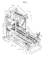
Figure 1 shows a perspective view of a folding apparatus according to the present invention for folding sheet packaging elements, with parts removed for clarity; -
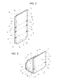
Figure 2 shows a larger-scale perspective view of a packaging element in the condition in which it is fed to the apparatus ofFigure 1 ; -
Figure 3 shows a perspective view of the packaging element ofFigure 2 in the condition in which it is released by the apparatus ofFigure 1 ; -
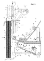
Figure 4 shows a larger-scale side view of the apparatus ofFigure 1 , with parts removed for clarity; and -
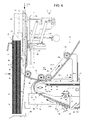
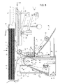
Figures 5 to 9 show larger-scale side views of a portion of the apparatus ofFigure 4 , in different operative conditions and with parts removed for clarity. -
Number 1 inFigures 1 and4 indicates as a whole a folding apparatus for foldingsheet packaging elements 2, in particular cardboard blanks designed to be transformed into packaging boxes (known per se and not shown) housing multiple packages or containers (known per se and not shown). - As shown in detail in
Figures 2 and4 to 9 , eachpackaging element 2 is fed to foldingapparatus 1 in a vertical configuration, in which it extends along a vertical plane and presents a substantially rectangular profile. In particular, in its vertical configuration, eachpackaging element 2 is delimited by two oppositelongitudinal sides Figure 2 ) and by two oppositetransversal sides longitudinal sides transversal side 4a is arranged at an upper position thantransversal side 4b. - Each
packaging element 2 is also provided with a plurality oflateral flaps 5 protruding fromsides - Each
packaging element 2 is also provided with three pairs of lateral cuts orrecesses 6, which are formed onopposite sides - Each
packaging element 2 may further comprise two or more transversal crease lines, in the present case three transversal crease lines referenced as 7a, 7b, 7c, along which thepackaging element 2 is destined to be folded to form the final packaging box. -
Transversal crease lines sides crease line 7a is adjacent toside 4a,crease line 7b is adjacent toside 4b andcrease line 7c is located at an intermediate position betweencrease lines -
Folding apparatus 1 is in particular adapted to fold eachpackaging element 2 alongcrease lines Figures 1 ,3 and9 ), with an intermediatehorizontal portion 8 delimited by thecrease lines portions intermediate portion 8 and having different heights therefrom (Figures 1 and3 ). In the present case,portion 9, delimited bytransverse side 4a, is taller thanportion 10 in the U-shaped configuration. - In the vertical configuration of each
packaging element 2,portion 9 is located at an upper position thanportion 8, which is in turn at an upper position thanportion 10. - According to a possible alternative not shown,
folding apparatus 1 may also produce the U-shaped configuration without providing any crease line on therelative packaging element 2. - With reference to
Figures 1 and4 to 9 ,folding apparatus 1 comprises: - a
support structure 11; - a
main conveying unit 12 mounted onsupport structure 11 and configured to sequentially receivepackaging elements 2 from afeeding station 13 and to continuously advance eachpackaging element 2 along a given path A, in the example shown defined by a horizontal direction; - forming
means 15 carried bymain conveying unit 12 and configured to cooperate in use with afirst face 2a of eachpackaging element 2 while the latter is advanced along path A; - an
auxiliary conveying unit 16 mounted onsupport structure 11 in a position partially facingmain conveying unit 12; and - folding means 18 advanced continuously by
auxiliary conveying unit 16 along an endless path Q, having a first portion Q1, distinct from path A, and a second portion Q2, which is in common, or aligned, with path A itself and along which the folding means 18 cooperate with asecond face 2b,opposite face 2a, of eachpackaging element 2 to fold the latter against formingmeans 15. - With reference to
Figures 1 and4 ,support structure 11 basically comprises ahorizontal base frame 20 and atower frame 21, which protrudes upwards from ahead portion 22 ofbase frame 20 and defines aninlet section 23 offolding apparatus 1. - In particular,
base frame 20 rests on the floor through a plurality of height-adjustable feet 24 and comprises two longitudinal supportingbeams 25 and a plurality of transverse supportingbeams 26, three in the example shown. In particular, longitudinal supportingbeams 25 extend parallel to path A, whilst transverse supportingbeams 26 extend orthogonally to path A and to the longitudinal supportingbeams 25. -
Tower frame 21 comprises fourstruts 27, vertically extending upwards in pairs from respective head portions of longitudinal supportingbeams 25;struts 27 are connected in pairs, in proximity of their tops, by respectivetransverse bars 28 parallel to transverse supportingbeams 26;struts 27 are also connected in pairs, in proximity of their tops, byrespective side rails 30 extending parallel to longitudinal supportingbeams 25. -
Support structure 11 further comprises a horizontalintermediate frame 31 arranged above and at a distance frombase frame 20 and supported bystruts 27 oftower frame 21 and byend struts 32, extending vertically upwards from respective longitudinal supportingbeams 25 at anoutlet section 33 offolding apparatus 1 and having smaller heights than those ofstruts 27.Intermediate frame 31 has a structure similar to that ofbase frame 20 and is not further described. -
Main conveying unit 12 is supported bybase frame 20 andintermediate frame 31 as well as by bottom portions ofstruts 27 and byend struts 32;main conveying unit 12 is located, for the most part, in the space delimited bybase frame 20intermediate frame 31,struts 27 andend struts 32. -
Auxiliary conveying unit 16 is instead entirely supported bytower frame 21 and is arranged, for the most part, in the space delimited by thestruts 27. -
Feeding station 13 comprises a pair of lateral retainers 35 (Figures 5 to 9 ) carried bystruts 27 oftower frame 21 atinlet section 23 and adapted to temporarily stoppackaging elements 2 arriving in their vertical configurations from an upstream processing apparatus or from an upstream magazine (not shown). - In particular, at
feeding station 13,packaging elements 2 are accumulated against each other and againstlateral retainers 35 so as to be compacted into abatch 36 ofadjacent packaging elements 2. More specifically, atfeeding station 13,packaging elements 2 are supported in their vertical configurations by lateral horizontal flaps (known per se and not shown) engaging respective opposite and alignedrecesses 6. - As visible in particular in
Figures 1 and4 ,main conveying unit 12 comprises a linearhorizontal transport branch 40, defining path A and along which formingmeans 15 andpackaging elements 2 are conveyed towardsoutlet section 33. In particular, during transfer fromfeeding station 13 tomain conveying unit 12, eachpackaging element 2 passes from the vertical configuration to a configuration in which it lies, at least partially, with itsface 2a ontransport branch 40. The way in whichpackaging elements 2 are transferred fromfeeding station 13 tomain conveying unit 12 will be explained in detail later on. -
Auxiliary conveying unit 16 is arranged betweenfeeding station 13 andmain conveying unit 12 as well as at an upper position than that ofmain conveying unit 12. - With reference to
Figures 1 , and4 to 9 , formingmeans 15 comprise a plurality of first formingelements 41 adapted to cooperate withcrease lines 7b ofpackaging elements 2, and a plurality of second formingelements 42 alternate to first formingelements 41 and adapted to cooperate withcrease lines 7c ofpackaging elements 2. - In practice, during advancement along path A, each
packaging element 2 is arranged between one first formingelement 41 and onesecond forming element 42; more specifically, the first formingelement 41 is arranged on the back of thepackaging element 2 and pushes it along path A, whilst the second formingelement 42 is placed in front of thepackaging element 2 itself. -
Main conveying unit 12 comprises afirst conveying device 43, carrying first formingelements 41, and asecond conveying device 44, carrying second formingelements 42;conveying devices operative branches transport branch 40 and lying on a common horizontal plane. - In particular,
conveying device 43 comprises twoparallel conveyors 45, to which first formingelements 41 are rigidly secured and which define an endless path P for the first formingelements 41 themselves. - In the example shown,
conveyors 45 comprise respective parallelendless chains 46 passing round a plurality of pairs of interconnectedtoothed wheels 48, four pairs in the example shown. One pair oftoothed wheels 48 is motorized to impart motion torespective chains 46. - First forming
elements 41 are secured torespective chains 46 and are uniformly distributed along thechains 46 themselves. - In particular, each first forming
element 41 projects from therespective chain 46 and has a shape resembling a set square, with a profile of a right-angled triangle. In particular, each first formingelement 41 is delimited by abase surface 49 attached to therespective chain 46, a formingsurface 50 orthogonal tochain 46 as well as tobase surface 49 and adapted to cooperate in use with arelative packaging element 2, and aslanted surface 51 connectingbase surface 49 and formingsurfaces 50. Formingsurface 50 of each first formingelement 41 extends orthogonally to thetransport branch 40 ofmain conveying unit 12 when such first formingelement 41 is advanced along path A. - Each
chain 46 preferably lies on a substantially vertical plane and has a profile shaped like an isosceles trapezium. - Each
chain 46 comprises: - a
horizontal transport portion 52 parallel to path A and defining, together withtransport portion 52 of theother chain 46,operative branch 43a; - a horizontal return portion 53, which is parallel to transport
portion 52, is shorter thantransport portion 52 and is arranged beneathtransport portion 52; and - slanted
connection portions transport portion 52 to corresponding end portions of return portion 53. - In particular,
connection portion 54 is adjacent toinlet section 23 offolding apparatus 1, whilstconnection portion 55 is adjacent tooutlet section 33 of thefolding apparatus 1 itself. - As visible in
Figure 1 , conveyingdevice 44 is arranged betweenconveyors 45 and has a structure very similar to that of conveyingdevice 43. - In particular, even in this case, conveying
device 44 comprises twoparallel conveyors 56, to which second formingelements 42 are rigidly secured and which define an endless path R - for the most part parallel to path P - for the second formingelements 42 themselves. - In the example shown,
conveyors 56 comprise respective parallelendless chains 57 passing round a plurality of pairs of interconnectedtoothed wheels 58, four pairs in this case. One pair oftoothed wheels 58 is motorized to impart motion torespective chains 57. -
Chains 57 are internally adjacent torespective chains 46 and define therebetween agap 47, whose function will be clarified later on. - Second forming
elements 42 are secured torespective chains 57 and are uniformly distributed along thechains 57 themselves. - In particular, each second forming
element 42 projects from therespective chain 57 and has a shape resembling a set square, with a profile of a right-angled triangle. In particular, each second formingelement 42 is delimited by abase surface 59 attached to therespective chain 57, a formingsurface 60 orthogonal tochain 57 as well as tobase surface 59 and adapted to cooperate in use with arelative packaging element 2, and aslanted surface 61 connectingbase surface 59 and formingsurface 60. - Forming
surface 60 of each second formingelement 42 extends orthogonally to thetransport branch 40 of main conveyingunit 12 when such second formingelement 42 is advanced along pathA. Forming surface 60 of each second formingelement 42faces forming surface 50 of the first formingelement 41 cooperating in use with thesame packaging element 2 and define, with the portion of thetransport branch 40 comprised therebetween, a U-shaped profile forming aseat 62, within which thepackaging element 2 itself is correspondingly folded by interaction with folding means 18. - Even in this case, each
chain 57 preferably lies on a substantially vertical plane and has a profile shaped like a trapezium. - Each
chain 57 comprises: - a
horizontal transport portion 63 coplanar with path A andtransport portion 52 ofchains 46 and defining, together withtransport portion 63 of theother chain 57,operative branch 44a; - a
horizontal return portion 64, which is parallel to transportportion 63, is shorter thantransport portion 63 and is arranged beneath the latter; and - slanted
connection portions transport portion 63 to corresponding end portions of thereturn portion 64. - In particular,
connection portion 65 is adjacent toinlet section 23 offolding apparatus 1, whilstconnection portion 66 is adjacent tooutlet section 33 of thefolding apparatus 1 itself. - As clearly shown in
Figures 1 and4 ,chains 57 are parallel tochains 46 except atconnection portions outlet section 33; as a matter of fact,transport portions 52 ofchains 46 are longer thantransport portions 63 ofchains 57 atoutlet section 33 to allow a completion of the pushing action onpackaging elements 2 by first formingelements 41 at the exit offolding apparatus 1. - With reference to
Figures 1 and4 to 9 , folding means 18 are carried by auxiliary conveyingunit 16 and comprise a plurality of first folding bars 71 adapted to foldpackaging elements 2 alongcrease lines 7c and against respective second formingelements 42, and a plurality of second folding bars 72 alternate tofolding bars 71 and adapted to foldpackaging elements 2 alongcrease lines 7b and against respective first formingelements 41. - In a manner analogous to main conveying
unit 12,auxiliary conveying unit 16 comprises a first conveyingdevice 73, carrying first folding bars 71, and a second conveyingdevice 74, carrying second folding bars 72; first conveyingdevice 73 and second conveyingdevice 74 haverespective folding branches operative branches unit 12, on a common horizontal plane. - In particular, first conveying
device 73 comprises twoparallel conveyors 75, to which first folding bars 71 are rigidly secured. - In the example shown,
conveyors 75 comprise respective parallelendless chains 76 passing round a plurality of pairs of interconnectedtoothed wheels 78. One pair oftoothed wheels 78 is motorized to impart motion torespective chains 76. - First folding bars 71 extend transversally to
chains 76 and interconnect them; more specifically, first folding bars 71 are secured at their opposite ends torespective chains 76 and are uniformly distributed along thechains 76 themselves. - Each
chain 76 preferably lies on a substantially vertical plane and comprises, by proceeding along path Q: - a
horizontal folding portion 82 extending in use within thegap 47 betweenchains 57 and coplanar withtransport portions chains portion 82 of theother chain 76; - an ascending ramp-shaped
portion 83, slantingly extending upwards from foldingportion 82; - a
return portion 84 facing foldingportion 82; - a
vertical transfer portion 85 facing feedingstation 13 and extending, in use, parallel to thepackaging elements 2 forming thebatch 36 at the feedingstation 13 itself; and - a descending ramp-shaped
portion 86 connectingtransfer portion 85 to foldingportion 82. - As visible in
Figure 1 , second conveyingdevice 74 is arranged betweenconveyors 75 and has a structure very similar to that of first conveyingdevice 73. - In particular, even in this case, second conveying
device 74 comprises twoparallel conveyors 87, to which second folding bars 72 are rigidly secured. - In the example shown,
conveyors 87 comprise respective parallelendless chains 88 passing round a plurality of pairs of interconnectedtoothed wheels 89. One pair oftoothed wheels 89 is motorized to impart motion torespective chains 88. -
Chains 88 are internally adjacent torespective chains 76 and are interconnected by second folding bars 72; more specifically, second folding bars 72 are secured at their opposite ends torespective chains 88 and are uniformly distributed along thechains 88 themselves. -
Chains 88 exactly have the same configurations aschains 76; therefore, the component parts ofchains 88 will be indicated in the following description and drawings with the same references as those used forchains 76. - Ramp-shaped
portions portions 84 andtransfer portions 85 ofchains folding portions 82 ofchains -
Transfer portions 85 ofchains packaging element 2 to transfer it from feedingstation 13 to main conveyingunit 12. - In particular,
folding apparatus 1 further comprises asuction head 90 for separating oneend packaging element 2 from the rest of thebatch 36 so as to allow insertion of first folding bars 71 and second folding bars 72 between the separatedend packaging element 2 and thebatch 36. - In practice,
suction head 90 is only used to separate theend packaging element 2 from the rest of thebatch 36, whilst the first folding bars 71 and the second folding bars 72, moving along part Q1A of path Q, act on the separatedend packaging element 2 to transfer it from feedingstation 13 to main conveyingunit 12. -
Suction head 90 is suspended, through an articulatedparallelogram 91, to towerframe 21 in a position facing feedingstation 13 and is movable towards and away from thebatch 36 between a rest position (Figure 9 ), in which thesuction head 90 is separated from thebatch 36, and an operative position (Figure 5 ), in which thesuction head 90 is adjacent to thebatch 36 to pick up theend packaging element 2 thereof. - In particular, in the rest position,
suction head 90 facesportion 9 of thepackaging element 2 to be separated from the rest of thebatch 36; in the operative position,suction head 90contacts portion 9 of thepackaging element 2 to be separated from thebatch 36 and suction is active. -
Suction head 90 moves substantially parallel to path A; in this way, during its movement from the operative position to the rest position,suction head 90 separates theend packaging element 2 from thebatch 36 by disengagingsuch packaging element 2 from the flaps on which it is suspended and by inclining it forward, towards main conveyingunit 12. - During this step, the separated
packaging element 2 rests with itsflap 5 ofside 4b on a fixedbottom plate 92 carried bysupport structure 11. -
Suction head 90 is advantageously moved between a pair of stop rails 93 adapted to define an abutment for theportion 9 of the separatedpackaging element 2. - By considering the movement of forward inclination of the separated
packaging element 2 towards main conveyingunit 12, stop rails 93 are arranged between the rest and operative position ofsuction head 90, so as to allow disengagement of thesuction head 90 from thepackaging element 2 prior to reaching the rest position. - As visible in
Figures 5 and7 , part Q1A of path Q advantageously extends between the rest position and the operative position ofsuction head 90, so as to allow interaction of first folding bars 71 and second folding bars 72 with the separatedpackaging elements 2 to transfer the latter to main conveyingunit 12. In addition, part Q1A of path Q extends between the rest position ofsuction head 90 and stoprails 93; in this way, the separatedpackaging element 2 extends transversally to part Q1A of path Q and can be intercepted by first folding bars 71 and second folding bars 72. - Operation of
folding apparatus 1 will be described with reference to the folding of onepackaging element 2 and as of an initial condition (Figure 5 ), in which: -
such packaging element 2 is in its vertical configuration againstlateral retainers 35 and cooperates withsuction head 90 is in its operative position; - the
first folding bar 71 andsecond folding bar 72 destined to cooperate with saidpackaging element 2 are moving along operative part Q1A of path Q towards feedingstation 13; and - the first forming
element 41 and the second formingelement 42, also destined to interact with the mentionedpackaging element 2, are moving alongportions 53, 64 ofrespective chains -
Suction head 90 is moved towards its rest position and retains, by suction,portion 9 of thepackaging element 9, which therefore moves together with thesuction head 90 itself and separates from thebatch 36. During this movement, thepackaging element 2 disengages from the flaps on which it is suspended and, thanks to its deformability, also disengages fromlateral retainers 35. In practice, thepackaging element 2 leans forward, towards main conveyingunit 12, and rests with itsflap 5 ofside 4b on bottom plate 92 (Figure 7 ). - The movement of the
packaging element 2 ends against stop rails 93, at whichsuction head 90 separates from thepackaging element 2 and reaches its rest position (Figure 7 ). In this condition, thepackaging element 2 extends obliquely with respect to part Q1A of path Q and transversally toportions chains packaging element 2 can be intercepted firstly by thefirst folding bar 71 and then by thesecond folding bar 72. - As shown in
Figure 8 , thefirst folding bar 71, by moving alongportions chains 76, bendsportions packaging element 2 ontotransport branch 40 of main conveyingunit 12. - In the meantime, the second forming
element 42 destined to cooperate withcrease line 7c of thepackaging element 2 precede thepackaging element 2 and thefirst folding bar 71 along path A; in this way, during advancement along portion Q2 of path Q, thefirst folding bar 71 folds thepackaging element 2 alongcrease line 7c and against formingsurfaces 60 of the second formingelements 42; at the end of this step, theportion 9 of thepackaging element 2 extends orthogonally to theportion 8 and is advanced along path A in abutment against formingsurfaces 60 of the second formingelements 42. - The
first folding bar 71 comprises, at opposite ends thereof, protrudingelements 100 that folds downwards the lateral flaps 5a interposed between thetransversal crease lines packaging element 2 in a direction perpendicular to path A. - Along the
subsequent portions 83 ofchains 76, thefirst folding bar 71 releases thepackaging element 2. - In the meantime, first forming
element 41 intercepts theportion 10 of thepackaging element 2 while thesecond folding bar 72, moving alongportions 86 ofchains 88, precedes the first formingelement 41 along path A. - Along
portions 82 ofchains 88 and alongportions 52 ofchains 46 in common with theportions 82, the first formingelements 41 and thefirst folding bar 72 cooperate with the respective opposite faces 2b, 2a of thepackaging element 2 to fold it alongcrease line 7b (Figure 9 ). - At the end of this step, the
packaging element 2 is therefore folded in the U-shaped configuration, in which it is housed withinseat 62, delimited by the second formingelements 42 on the front side, with respect to path A, and by the first formingelements 41 on the back side. - Along the
portions 83 ofchains 88, even thefolding bar 72 releases thepackaging element 2, which is therefore advanced towardsoutlet section 33 by the first formingelements 41 and the second formingelements 42. - In particular, in the proximity of
outlet section 33, the second formingelements 42 move away from thepackaging element 2 by deviating alongconnection portions 66 ofchains 57; thepackaging element 2 is therefore pushed tooutlet section 33 by first formingelements 41 only, prosecuting along the end part oftransport portions 52 ofchains 46. - The advantages of
folding apparatus 1 according to the present invention will be clear from the foregoing description. - In particular, the described solution, with folding means 18 acting continuously on the
packaging elements 2 to fold them against formingmeans 15 while being advanced along path A, allows to reach very high processing speeds as well as an improved reliability with respect to known solutions. - In addition, by folding the
packaging elements 2 onto continuously-moving mechanical reference elements defined by formingmeans 15, instead of onto the packages or containers to be housed in the final packaging boxes, makes this operation independent from the weight or format of such packages or containers as well as from the material and/or format and/or thickness of thepackaging elements 2. - In addition, the use of suction is limited to separate the
packaging element 2 to be folded from the blank 36, while the transfer ofsuch packaging element 2 to main conveyingunit 12 is performed by the same folding means 18 used for folding thepackaging elements 2. This also contributes to increase the processing speed, as it is not necessary to wait for thesuction head 90 to perform the entire transfer. - Furthermore, the structures of conveying
devices elements 41 and second formingelements 42 as well as between first folding bars 71 and second formingbars 72 to adapt to different formats ofpackaging elements 2 to be folded or different distances between the crease lines ofsuch packaging elements 2. - Clearly, changes may be made to
folding apparatus 1 as described herein without, however, departing from the scope of protection as defined in the accompanying claims. - In particular,
chains - In addition, each pair of folding bars 71, 72 may be replaced by one folding plate, whose front and rear edges perform the same functions as the replaced folding bars 71, 72.
Claims (16)
- A folding apparatus (1) for folding sheet packaging elements (2), characterized by comprising:- main conveying means (12) configured to sequentially receive said packaging elements (2) from a feeding station (13) and to advance each packaging element (2) along a first path (A);- forming means (15) carried by said main conveying means (12) and configured to cooperate in use with a first face (2b) of each packaging element (2) while said packaging element (2) is advanced along said first path (A); and- folding means (18) advanced by auxiliary conveying means (16) along a second path (Q), having a first portion (Q1) distinct from said first path (A) and a second portion (Q2) that is in common with said first path (A) and along which said folding means (18) cooperate with a second face (2a), opposite the first face (2b), of each packaging element (2) to fold the packaging element (2) against said forming means (15).
- The apparatus as claimed in claim 1, wherein said forming means (15) and said folding means (18) are continuously advanced along said first and second path (A, Q) by said main conveying means (12) and auxiliary conveying means (16).
- The apparatus as claimed in claim 1, or 2, wherein said forming means (15) are rigidly secured to said main conveying means (12).
- The apparatus as claimed in any one of the foregoing claims, wherein said main conveying means (12) comprise a linear transport branch (40) defining said first path (A).
- The apparatus as claimed in claim 4, wherein said forming means (15) comprise at least a first forming surface (50) transversal to said transport branch (40) and at least a second forming surface (60) facing said first forming surface (50) and also transversal to said transport branch (40); and wherein said first forming surface (50) and said second forming surface (60) define, with a portion of said transport branch (40) comprised therebetween, a U-shaped profile forming seat (62), within which a respective packaging element (2) is correspondingly folded in use by interaction with said folding means (18).
- The apparatus as claimed in any one of the foregoing claims, wherein said feeding station (13) is configured to receive said packaging elements (2) extending transversally to said first path (A); and wherein said first portion (Q1) of said second path (Q) has an operative part (Q1A) extending adjacent to said feeding station (13) and along which said folding means (18) interact in use with each packaging element (2) to transfer said packaging element (2) from said feeding station (13) to said main conveying means (12).
- The apparatus as claimed in claim 6, wherein said feeding station (13) is configured to receive said packaging elements (2) compacted into a batch (36); and wherein said apparatus (1) further comprises a suction head (90) for separating one packaging element (2) from the rest of the batch (36) so as to allow insertion of said folding means (18) between said separated packaging element (2) and said batch (36).
- The apparatus as claimed in claim 7, wherein said suction head (90) is movable towards and away from said batch (36) between a rest position, in which said suction head (90) is separated from said batch (36), and an operative position, in which said suction head (90) is adjacent to said batch (36) to pick up said packaging element (2); and wherein said operative part (Q1A) of said first portion (Q1) of said second path (Q) extends between said rest position and said operative position of said suction head (90).
- The apparatus as claimed in claim 8, and further comprising stop means (93) configured to define an abutment for the separated packaging element (2) before said suction head (90) reaches said rest position while moving from said operative position, so as to allow release of the separated packaging element (2) from said suction head (90).
- The apparatus as claimed in any one of claims 6 to 9, wherein said transport branch (40) of said main conveying means (12) extends horizontally; and wherein said operative part (Q1A) of said first portion (Q1) of said second path (Q) extends vertically and parallel in use to said packaging elements (2) at said feeding station (13).
- The apparatus as claimed in any one of the foregoing claims, wherein said auxiliary conveying means (16) are arranged between said feeding station (13) and said main conveying means (12) as well as above said main conveying means (12).
- The apparatus as claimed in any one of claims 5 to 11, wherein said main conveying means (12) comprise a first conveying device (43), carrying said first forming surface (50), and a second conveying device (44), carrying said second forming surface (60); and wherein said first conveying device (43) and said second conveying device (44) have respective operative branches (43a, 44a) parallel to one another and defining said transport branch (40).
- The apparatus as claimed in claim 12, wherein said first conveying device (43) comprises two parallel first conveyors (45); and wherein said second conveying device (44) is arranged between said first conveyors (45).
- The apparatus as claimed in any one of claims 5 to 13, wherein said folding means (18) comprise at least one first folding bar (71) and at least one second folding bar (72) spaced from said first folding bar (71) along said second path (Q), said first folding bar (71) and said second forming bar (72) being adapted to cooperate with said first forming surface (50) and said second forming surface (50, 60) to fold said packaging elements (2).
- The apparatus as claimed in claim 14, wherein said auxiliary conveying means (16) comprise a third conveying device (73), carrying said first folding bar (71), and a fourth conveying device (74), carrying said second folding bar (72); and wherein said third conveying device (73) and said fourth conveying device (74) have respective folding branches (73a, 74a) parallel to one another and lying on a common plane with said transport branch (40).
- The apparatus as claimed in claim 15, wherein said third conveying device (73) comprises two parallel second conveyors (75); and wherein said fourth conveying device (74) is arranged between said second conveyors (75).
Priority Applications (5)
| Application Number | Priority Date | Filing Date | Title |
|---|---|---|---|
| EP15157205.4A EP3064343B1 (en) | 2015-03-02 | 2015-03-02 | A folding apparatus for folding sheet packaging elements |
| JP2017544343A JP6778204B2 (en) | 2015-03-02 | 2016-02-26 | Folding device for folding seat package parts |
| PCT/EP2016/054067 WO2016139138A1 (en) | 2015-03-02 | 2016-02-26 | A folding apparatus for folding sheet packaging elements |
| CN201680011211.2A CN107249870B (en) | 2015-03-02 | 2016-02-26 | Folding equipment for folding sheet packaging elements |
| US15/552,313 US11040511B2 (en) | 2015-03-02 | 2016-02-26 | Folding apparatus for folding sheet packaging elements |
Applications Claiming Priority (1)
| Application Number | Priority Date | Filing Date | Title |
|---|---|---|---|
| EP15157205.4A EP3064343B1 (en) | 2015-03-02 | 2015-03-02 | A folding apparatus for folding sheet packaging elements |
Publications (2)
| Publication Number | Publication Date |
|---|---|
| EP3064343A1 true EP3064343A1 (en) | 2016-09-07 |
| EP3064343B1 EP3064343B1 (en) | 2019-01-30 |
Family
ID=52595192
Family Applications (1)
| Application Number | Title | Priority Date | Filing Date |
|---|---|---|---|
| EP15157205.4A Active EP3064343B1 (en) | 2015-03-02 | 2015-03-02 | A folding apparatus for folding sheet packaging elements |
Country Status (5)
| Country | Link |
|---|---|
| US (1) | US11040511B2 (en) |
| EP (1) | EP3064343B1 (en) |
| JP (1) | JP6778204B2 (en) |
| CN (1) | CN107249870B (en) |
| WO (1) | WO2016139138A1 (en) |
Cited By (1)
| Publication number | Priority date | Publication date | Assignee | Title |
|---|---|---|---|---|
| CN108859243A (en) * | 2018-08-27 | 2018-11-23 | 唐山新联印刷机械集团有限公司 | A kind of automatic feeding of packing case and wear handle method and apparatus |
Families Citing this family (2)
| Publication number | Priority date | Publication date | Assignee | Title |
|---|---|---|---|---|
| EP3064343B1 (en) * | 2015-03-02 | 2019-01-30 | Tetra Laval Holdings & Finance S.A. | A folding apparatus for folding sheet packaging elements |
| KR102108108B1 (en) * | 2018-09-12 | 2020-05-11 | 한국철도기술연구원 | Apparatus for folding and unfolding foldable container and automatic folding system having the same |
Citations (6)
| Publication number | Priority date | Publication date | Assignee | Title |
|---|---|---|---|---|
| US3325977A (en) * | 1962-11-23 | 1967-06-20 | Kirsten Rolf | Packing machine |
| DE1611610A1 (en) * | 1968-02-13 | 1971-01-14 | Siefvert U Fornander Ab | Device for producing open boxes from cardboard or the like. |
| US3716962A (en) * | 1970-12-18 | 1973-02-20 | American Can Co | Carton flap folding mechanism |
| WO2004073964A2 (en) * | 2003-02-19 | 2004-09-02 | Meadwestvaco Packaging Systems Llc | Box forming mechanism & method |
| US20100064633A1 (en) * | 2008-08-07 | 2010-03-18 | R.A. Jones & Co. Inc. | Short depth carton feed drive |
| US20150031519A1 (en) * | 2013-07-23 | 2015-01-29 | G.D Societa’ Per Azioni | Packing unit and method for folding a blank on a packing machine |
Family Cites Families (17)
| Publication number | Priority date | Publication date | Assignee | Title |
|---|---|---|---|---|
| US3461642A (en) * | 1966-10-21 | 1969-08-19 | American Can Co | Method and machine for forming and sealing a carton |
| US3401609A (en) * | 1966-11-14 | 1968-09-17 | Hoerner Waldorf Corp | Package forming apparatus |
| SE369870B (en) * | 1972-12-21 | 1974-09-23 | Sprinter Pack Ab | |
| US4429864A (en) * | 1981-06-22 | 1984-02-07 | R. A. Jones & Co. Inc. | High speed carton feeder |
| JPS59190105A (en) * | 1983-04-13 | 1984-10-27 | Toppan Printing Co Ltd | Article interval changing device of article transporter |
| US4571236A (en) * | 1983-12-05 | 1986-02-18 | R. A. Jones & Co. Inc. | Carton squaring mechanism |
| US4917663A (en) * | 1988-05-24 | 1990-04-17 | Apv Douglas Machine Corporation | Packaging machine with direct blank setup |
| JPH06270952A (en) * | 1993-03-15 | 1994-09-27 | Calpis Food Ind Co Ltd:The | Device for drawing out sheet in caser |
| US5531661A (en) * | 1994-10-03 | 1996-07-02 | Riverwood International Corporation | Carrier sleeve erecting apparatus and method |
| CH687818A5 (en) * | 1994-11-08 | 1997-02-28 | Involdes Ag | Means for feeding a packaging machine. |
| EP0883565B1 (en) * | 1996-02-23 | 2000-07-19 | Böwe Systec Ag | Conveyor and gathering system |
| AU740746B2 (en) * | 1998-03-09 | 2001-11-15 | Mondi Technology Investments S.A. | Apparatus and method for scoring and folding sheet material |
| US20060084560A1 (en) * | 2003-02-19 | 2006-04-20 | Pascal Martini | Box forming mechanism & method |
| US7163502B2 (en) * | 2005-02-14 | 2007-01-16 | Thiele Technologies, Inc. | Carton erecting apparatus |
| EP2284084B1 (en) * | 2009-08-11 | 2012-07-25 | Tetra Laval Holdings & Finance S.A. | Folding unit for pourable food product packaging machines |
| ES2535810T3 (en) * | 2011-10-31 | 2015-05-18 | Tetra Laval Holdings & Finance S.A. | Folding unit and method to produce containers of food products that can be poured |
| EP3064343B1 (en) * | 2015-03-02 | 2019-01-30 | Tetra Laval Holdings & Finance S.A. | A folding apparatus for folding sheet packaging elements |
-
2015
- 2015-03-02 EP EP15157205.4A patent/EP3064343B1/en active Active
-
2016
- 2016-02-26 JP JP2017544343A patent/JP6778204B2/en active Active
- 2016-02-26 US US15/552,313 patent/US11040511B2/en active Active
- 2016-02-26 CN CN201680011211.2A patent/CN107249870B/en active Active
- 2016-02-26 WO PCT/EP2016/054067 patent/WO2016139138A1/en not_active Ceased
Patent Citations (6)
| Publication number | Priority date | Publication date | Assignee | Title |
|---|---|---|---|---|
| US3325977A (en) * | 1962-11-23 | 1967-06-20 | Kirsten Rolf | Packing machine |
| DE1611610A1 (en) * | 1968-02-13 | 1971-01-14 | Siefvert U Fornander Ab | Device for producing open boxes from cardboard or the like. |
| US3716962A (en) * | 1970-12-18 | 1973-02-20 | American Can Co | Carton flap folding mechanism |
| WO2004073964A2 (en) * | 2003-02-19 | 2004-09-02 | Meadwestvaco Packaging Systems Llc | Box forming mechanism & method |
| US20100064633A1 (en) * | 2008-08-07 | 2010-03-18 | R.A. Jones & Co. Inc. | Short depth carton feed drive |
| US20150031519A1 (en) * | 2013-07-23 | 2015-01-29 | G.D Societa’ Per Azioni | Packing unit and method for folding a blank on a packing machine |
Cited By (2)
| Publication number | Priority date | Publication date | Assignee | Title |
|---|---|---|---|---|
| CN108859243A (en) * | 2018-08-27 | 2018-11-23 | 唐山新联印刷机械集团有限公司 | A kind of automatic feeding of packing case and wear handle method and apparatus |
| CN108859243B (en) * | 2018-08-27 | 2023-04-11 | 唐山新联印刷机械集团有限公司 | Automatic paper feeding and handle penetrating method and device for packing box |
Also Published As
| Publication number | Publication date |
|---|---|
| JP6778204B2 (en) | 2020-10-28 |
| US20180036986A1 (en) | 2018-02-08 |
| CN107249870B (en) | 2019-10-25 |
| JP2018507124A (en) | 2018-03-15 |
| WO2016139138A1 (en) | 2016-09-09 |
| US11040511B2 (en) | 2021-06-22 |
| CN107249870A (en) | 2017-10-13 |
| EP3064343B1 (en) | 2019-01-30 |
Similar Documents
| Publication | Publication Date | Title |
|---|---|---|
| US4424658A (en) | Method and apparatus for the production of a double package | |
| EP3566981B1 (en) | Outfeed device for a packaging assembly and packaging assembly comprising an outfeed device | |
| JPH11503096A (en) | Multi-pack packaging equipment | |
| EP2392451A2 (en) | Transfer apparatus for a line end of a folder-gluer | |
| CN104271477A (en) | Apparatus for orderly supply of a group of trays to a sealing machine of said trays, with application of a covering film | |
| HU220152B (en) | Method and apparatus for packaging series of touching or overlapping arranged articles | |
| US11040511B2 (en) | Folding apparatus for folding sheet packaging elements | |
| CN108528820B (en) | Device for treating objects and method for exchanging at least one transport module and at least one work module of a device | |
| CN104334480A (en) | Method and apparatus for horizontally transferring layers of articles between adjacent modules | |
| US20030051438A1 (en) | Apparatus and process for packaging piece goods | |
| CN103231821B (en) | Wrapping forming method of chip box blanks | |
| KR101603419B1 (en) | Three-sided wrapped food accumulator | |
| EP2616340B1 (en) | A device and a method for packaging substantially flat products in a box | |
| CN109533482A (en) | A kind of side-pressing device of the manufacture vanning integration apparatus of pop can packing case | |
| EP0439438A2 (en) | Device for forming vertical piles of items | |
| JP2023534019A (en) | Carton stack feeder | |
| JP6121372B2 (en) | Accessories supply device for horizontal bag making and filling machine | |
| JP6381923B2 (en) | Accumulator | |
| CN107257767B (en) | Magazines for sheet packaging elements | |
| EP3326923A1 (en) | A folding apparatus for folding sheet packaging elements | |
| JP6547475B2 (en) | Article stacking device | |
| KR101502229B1 (en) | Method and device for accumulating articles to be accumulated | |
| JP6300151B2 (en) | Boxing method and boxing device for flat article | |
| JP2019156442A (en) | Packaging device | |
| JP2004299709A (en) | Packaging apparatus |
Legal Events
| Date | Code | Title | Description |
|---|---|---|---|
| PUAI | Public reference made under article 153(3) epc to a published international application that has entered the european phase |
Free format text: ORIGINAL CODE: 0009012 |
|
| AK | Designated contracting states |
Kind code of ref document: A1 Designated state(s): AL AT BE BG CH CY CZ DE DK EE ES FI FR GB GR HR HU IE IS IT LI LT LU LV MC MK MT NL NO PL PT RO RS SE SI SK SM TR |
|
| AX | Request for extension of the european patent |
Extension state: BA ME |
|
| STAA | Information on the status of an ep patent application or granted ep patent |
Free format text: STATUS: REQUEST FOR EXAMINATION WAS MADE |
|
| 17P | Request for examination filed |
Effective date: 20170307 |
|
| RBV | Designated contracting states (corrected) |
Designated state(s): AL AT BE BG CH CY CZ DE DK EE ES FI FR GB GR HR HU IE IS IT LI LT LU LV MC MK MT NL NO PL PT RO RS SE SI SK SM TR |
|
| GRAP | Despatch of communication of intention to grant a patent |
Free format text: ORIGINAL CODE: EPIDOSNIGR1 |
|
| STAA | Information on the status of an ep patent application or granted ep patent |
Free format text: STATUS: GRANT OF PATENT IS INTENDED |
|
| RIC1 | Information provided on ipc code assigned before grant |
Ipc: B31B 50/58 20170101ALI20180731BHEP Ipc: B31B 50/36 20170101ALI20180731BHEP Ipc: B31B 110/35 20170101ALN20180731BHEP Ipc: B31B 50/07 20170101AFI20180731BHEP Ipc: B31B 100/00 20170101ALN20180731BHEP |
|
| INTG | Intention to grant announced |
Effective date: 20180905 |
|
| GRAJ | Information related to disapproval of communication of intention to grant by the applicant or resumption of examination proceedings by the epo deleted |
Free format text: ORIGINAL CODE: EPIDOSDIGR1 |
|
| STAA | Information on the status of an ep patent application or granted ep patent |
Free format text: STATUS: REQUEST FOR EXAMINATION WAS MADE |
|
| REG | Reference to a national code |
Ref country code: DE Ref legal event code: R079 Ref document number: 602015023860 Country of ref document: DE Free format text: PREVIOUS MAIN CLASS: B31B0001060000 Ipc: B31B0050070000 |
|
| GRAP | Despatch of communication of intention to grant a patent |
Free format text: ORIGINAL CODE: EPIDOSNIGR1 |
|
| STAA | Information on the status of an ep patent application or granted ep patent |
Free format text: STATUS: GRANT OF PATENT IS INTENDED |
|
| GRAS | Grant fee paid |
Free format text: ORIGINAL CODE: EPIDOSNIGR3 |
|
| INTC | Intention to grant announced (deleted) | ||
| RIC1 | Information provided on ipc code assigned before grant |
Ipc: B31B 50/36 20170101ALI20181113BHEP Ipc: B31B 50/58 20170101ALI20181113BHEP Ipc: B31B 110/35 20170101ALN20181113BHEP Ipc: B31B 100/00 20170101ALN20181113BHEP Ipc: B31B 50/07 20170101AFI20181113BHEP |
|
| INTG | Intention to grant announced |
Effective date: 20181129 |
|
| GRAA | (expected) grant |
Free format text: ORIGINAL CODE: 0009210 |
|
| STAA | Information on the status of an ep patent application or granted ep patent |
Free format text: STATUS: THE PATENT HAS BEEN GRANTED |
|
| AK | Designated contracting states |
Kind code of ref document: B1 Designated state(s): AL AT BE BG CH CY CZ DE DK EE ES FI FR GB GR HR HU IE IS IT LI LT LU LV MC MK MT NL NO PL PT RO RS SE SI SK SM TR |
|
| REG | Reference to a national code |
Ref country code: GB Ref legal event code: FG4D |
|
| REG | Reference to a national code |
Ref country code: CH Ref legal event code: EP |
|
| RIC2 | Information provided on ipc code assigned after grant |
Ipc: B31B 110/35 20170101ALN20181113BHEP Ipc: B31B 50/07 20170101AFI20181113BHEP Ipc: B31B 50/36 20170101ALI20181113BHEP Ipc: B31B 100/00 20170101ALN20181113BHEP Ipc: B31B 50/58 20170101ALI20181113BHEP |
|
| REG | Reference to a national code |
Ref country code: AT Ref legal event code: REF Ref document number: 1092906 Country of ref document: AT Kind code of ref document: T Effective date: 20190215 |
|
| REG | Reference to a national code |
Ref country code: IE Ref legal event code: FG4D |
|
| REG | Reference to a national code |
Ref country code: DE Ref legal event code: R096 Ref document number: 602015023860 Country of ref document: DE |
|
| REG | Reference to a national code |
Ref country code: LT Ref legal event code: MG4D |
|
| REG | Reference to a national code |
Ref country code: NL Ref legal event code: MP Effective date: 20190130 |
|
| PG25 | Lapsed in a contracting state [announced via postgrant information from national office to epo] |
Ref country code: LT Free format text: LAPSE BECAUSE OF FAILURE TO SUBMIT A TRANSLATION OF THE DESCRIPTION OR TO PAY THE FEE WITHIN THE PRESCRIBED TIME-LIMIT Effective date: 20190130 Ref country code: ES Free format text: LAPSE BECAUSE OF FAILURE TO SUBMIT A TRANSLATION OF THE DESCRIPTION OR TO PAY THE FEE WITHIN THE PRESCRIBED TIME-LIMIT Effective date: 20190130 Ref country code: NL Free format text: LAPSE BECAUSE OF FAILURE TO SUBMIT A TRANSLATION OF THE DESCRIPTION OR TO PAY THE FEE WITHIN THE PRESCRIBED TIME-LIMIT Effective date: 20190130 Ref country code: SE Free format text: LAPSE BECAUSE OF FAILURE TO SUBMIT A TRANSLATION OF THE DESCRIPTION OR TO PAY THE FEE WITHIN THE PRESCRIBED TIME-LIMIT Effective date: 20190130 Ref country code: PL Free format text: LAPSE BECAUSE OF FAILURE TO SUBMIT A TRANSLATION OF THE DESCRIPTION OR TO PAY THE FEE WITHIN THE PRESCRIBED TIME-LIMIT Effective date: 20190130 Ref country code: NO Free format text: LAPSE BECAUSE OF FAILURE TO SUBMIT A TRANSLATION OF THE DESCRIPTION OR TO PAY THE FEE WITHIN THE PRESCRIBED TIME-LIMIT Effective date: 20190430 Ref country code: PT Free format text: LAPSE BECAUSE OF FAILURE TO SUBMIT A TRANSLATION OF THE DESCRIPTION OR TO PAY THE FEE WITHIN THE PRESCRIBED TIME-LIMIT Effective date: 20190530 Ref country code: FI Free format text: LAPSE BECAUSE OF FAILURE TO SUBMIT A TRANSLATION OF THE DESCRIPTION OR TO PAY THE FEE WITHIN THE PRESCRIBED TIME-LIMIT Effective date: 20190130 |
|
| REG | Reference to a national code |
Ref country code: AT Ref legal event code: MK05 Ref document number: 1092906 Country of ref document: AT Kind code of ref document: T Effective date: 20190130 |
|
| PG25 | Lapsed in a contracting state [announced via postgrant information from national office to epo] |
Ref country code: HR Free format text: LAPSE BECAUSE OF FAILURE TO SUBMIT A TRANSLATION OF THE DESCRIPTION OR TO PAY THE FEE WITHIN THE PRESCRIBED TIME-LIMIT Effective date: 20190130 Ref country code: RS Free format text: LAPSE BECAUSE OF FAILURE TO SUBMIT A TRANSLATION OF THE DESCRIPTION OR TO PAY THE FEE WITHIN THE PRESCRIBED TIME-LIMIT Effective date: 20190130 Ref country code: LV Free format text: LAPSE BECAUSE OF FAILURE TO SUBMIT A TRANSLATION OF THE DESCRIPTION OR TO PAY THE FEE WITHIN THE PRESCRIBED TIME-LIMIT Effective date: 20190130 Ref country code: BG Free format text: LAPSE BECAUSE OF FAILURE TO SUBMIT A TRANSLATION OF THE DESCRIPTION OR TO PAY THE FEE WITHIN THE PRESCRIBED TIME-LIMIT Effective date: 20190430 Ref country code: IS Free format text: LAPSE BECAUSE OF FAILURE TO SUBMIT A TRANSLATION OF THE DESCRIPTION OR TO PAY THE FEE WITHIN THE PRESCRIBED TIME-LIMIT Effective date: 20190530 Ref country code: GR Free format text: LAPSE BECAUSE OF FAILURE TO SUBMIT A TRANSLATION OF THE DESCRIPTION OR TO PAY THE FEE WITHIN THE PRESCRIBED TIME-LIMIT Effective date: 20190501 |
|
| PG25 | Lapsed in a contracting state [announced via postgrant information from national office to epo] |
Ref country code: SK Free format text: LAPSE BECAUSE OF FAILURE TO SUBMIT A TRANSLATION OF THE DESCRIPTION OR TO PAY THE FEE WITHIN THE PRESCRIBED TIME-LIMIT Effective date: 20190130 Ref country code: MC Free format text: LAPSE BECAUSE OF FAILURE TO SUBMIT A TRANSLATION OF THE DESCRIPTION OR TO PAY THE FEE WITHIN THE PRESCRIBED TIME-LIMIT Effective date: 20190130 Ref country code: AL Free format text: LAPSE BECAUSE OF FAILURE TO SUBMIT A TRANSLATION OF THE DESCRIPTION OR TO PAY THE FEE WITHIN THE PRESCRIBED TIME-LIMIT Effective date: 20190130 Ref country code: CZ Free format text: LAPSE BECAUSE OF FAILURE TO SUBMIT A TRANSLATION OF THE DESCRIPTION OR TO PAY THE FEE WITHIN THE PRESCRIBED TIME-LIMIT Effective date: 20190130 Ref country code: RO Free format text: LAPSE BECAUSE OF FAILURE TO SUBMIT A TRANSLATION OF THE DESCRIPTION OR TO PAY THE FEE WITHIN THE PRESCRIBED TIME-LIMIT Effective date: 20190130 Ref country code: DK Free format text: LAPSE BECAUSE OF FAILURE TO SUBMIT A TRANSLATION OF THE DESCRIPTION OR TO PAY THE FEE WITHIN THE PRESCRIBED TIME-LIMIT Effective date: 20190130 Ref country code: EE Free format text: LAPSE BECAUSE OF FAILURE TO SUBMIT A TRANSLATION OF THE DESCRIPTION OR TO PAY THE FEE WITHIN THE PRESCRIBED TIME-LIMIT Effective date: 20190130 |
|
| REG | Reference to a national code |
Ref country code: CH Ref legal event code: PL Ref country code: DE Ref legal event code: R097 Ref document number: 602015023860 Country of ref document: DE |
|
| PG25 | Lapsed in a contracting state [announced via postgrant information from national office to epo] |
Ref country code: SM Free format text: LAPSE BECAUSE OF FAILURE TO SUBMIT A TRANSLATION OF THE DESCRIPTION OR TO PAY THE FEE WITHIN THE PRESCRIBED TIME-LIMIT Effective date: 20190130 Ref country code: LU Free format text: LAPSE BECAUSE OF NON-PAYMENT OF DUE FEES Effective date: 20190302 |
|
| REG | Reference to a national code |
Ref country code: BE Ref legal event code: MM Effective date: 20190331 |
|
| PLBE | No opposition filed within time limit |
Free format text: ORIGINAL CODE: 0009261 |
|
| STAA | Information on the status of an ep patent application or granted ep patent |
Free format text: STATUS: NO OPPOSITION FILED WITHIN TIME LIMIT |
|
| GBPC | Gb: european patent ceased through non-payment of renewal fee |
Effective date: 20190430 |
|
| PG25 | Lapsed in a contracting state [announced via postgrant information from national office to epo] |
Ref country code: AT Free format text: LAPSE BECAUSE OF FAILURE TO SUBMIT A TRANSLATION OF THE DESCRIPTION OR TO PAY THE FEE WITHIN THE PRESCRIBED TIME-LIMIT Effective date: 20190130 |
|
| 26N | No opposition filed |
Effective date: 20191031 |
|
| PG25 | Lapsed in a contracting state [announced via postgrant information from national office to epo] |
Ref country code: LI Free format text: LAPSE BECAUSE OF NON-PAYMENT OF DUE FEES Effective date: 20190331 Ref country code: CH Free format text: LAPSE BECAUSE OF NON-PAYMENT OF DUE FEES Effective date: 20190331 Ref country code: IE Free format text: LAPSE BECAUSE OF NON-PAYMENT OF DUE FEES Effective date: 20190302 Ref country code: GB Free format text: LAPSE BECAUSE OF NON-PAYMENT OF DUE FEES Effective date: 20190430 |
|
| PG25 | Lapsed in a contracting state [announced via postgrant information from national office to epo] |
Ref country code: BE Free format text: LAPSE BECAUSE OF NON-PAYMENT OF DUE FEES Effective date: 20190331 Ref country code: SI Free format text: LAPSE BECAUSE OF FAILURE TO SUBMIT A TRANSLATION OF THE DESCRIPTION OR TO PAY THE FEE WITHIN THE PRESCRIBED TIME-LIMIT Effective date: 20190130 Ref country code: FR Free format text: LAPSE BECAUSE OF NON-PAYMENT OF DUE FEES Effective date: 20190330 |
|
| PG25 | Lapsed in a contracting state [announced via postgrant information from national office to epo] |
Ref country code: TR Free format text: LAPSE BECAUSE OF FAILURE TO SUBMIT A TRANSLATION OF THE DESCRIPTION OR TO PAY THE FEE WITHIN THE PRESCRIBED TIME-LIMIT Effective date: 20190130 |
|
| PG25 | Lapsed in a contracting state [announced via postgrant information from national office to epo] |
Ref country code: MT Free format text: LAPSE BECAUSE OF NON-PAYMENT OF DUE FEES Effective date: 20190302 |
|
| PG25 | Lapsed in a contracting state [announced via postgrant information from national office to epo] |
Ref country code: CY Free format text: LAPSE BECAUSE OF FAILURE TO SUBMIT A TRANSLATION OF THE DESCRIPTION OR TO PAY THE FEE WITHIN THE PRESCRIBED TIME-LIMIT Effective date: 20190130 |
|
| PG25 | Lapsed in a contracting state [announced via postgrant information from national office to epo] |
Ref country code: HU Free format text: LAPSE BECAUSE OF FAILURE TO SUBMIT A TRANSLATION OF THE DESCRIPTION OR TO PAY THE FEE WITHIN THE PRESCRIBED TIME-LIMIT; INVALID AB INITIO Effective date: 20150302 |
|
| PG25 | Lapsed in a contracting state [announced via postgrant information from national office to epo] |
Ref country code: MK Free format text: LAPSE BECAUSE OF FAILURE TO SUBMIT A TRANSLATION OF THE DESCRIPTION OR TO PAY THE FEE WITHIN THE PRESCRIBED TIME-LIMIT Effective date: 20190130 |
|
| P01 | Opt-out of the competence of the unified patent court (upc) registered |
Effective date: 20230426 |
|
| PGFP | Annual fee paid to national office [announced via postgrant information from national office to epo] |
Ref country code: DE Payment date: 20260320 Year of fee payment: 12 |
|
| PGFP | Annual fee paid to national office [announced via postgrant information from national office to epo] |
Ref country code: IT Payment date: 20260320 Year of fee payment: 12 |