EP3064315A1 - A tool for machining an object - Google Patents
A tool for machining an object Download PDFInfo
- Publication number
- EP3064315A1 EP3064315A1 EP16156884.5A EP16156884A EP3064315A1 EP 3064315 A1 EP3064315 A1 EP 3064315A1 EP 16156884 A EP16156884 A EP 16156884A EP 3064315 A1 EP3064315 A1 EP 3064315A1
- Authority
- EP
- European Patent Office
- Prior art keywords
- tool
- controller
- machining
- control
- sensor
- Prior art date
- Legal status (The legal status is an assumption and is not a legal conclusion. Google has not performed a legal analysis and makes no representation as to the accuracy of the status listed.)
- Granted
Links
Images





Classifications
-
- G—PHYSICS
- G05—CONTROLLING; REGULATING
- G05B—CONTROL OR REGULATING SYSTEMS IN GENERAL; FUNCTIONAL ELEMENTS OF SUCH SYSTEMS; MONITORING OR TESTING ARRANGEMENTS FOR SUCH SYSTEMS OR ELEMENTS
- G05B19/00—Program-control systems
- G05B19/02—Program-control systems electric
- G05B19/18—Numerical control [NC], i.e. automatically operating machines, in particular machine tools, e.g. in a manufacturing environment, so as to execute positioning, movement or co-ordinated operations by means of program data in numerical form
- G05B19/19—Numerical control [NC], i.e. automatically operating machines, in particular machine tools, e.g. in a manufacturing environment, so as to execute positioning, movement or co-ordinated operations by means of program data in numerical form characterised by positioning or contouring control systems, e.g. to control position from one programmed point to another or to control movement along a programmed continuous path
-
- B—PERFORMING OPERATIONS; TRANSPORTING
- B23—MACHINE TOOLS; METAL-WORKING NOT OTHERWISE PROVIDED FOR
- B23B—TURNING; BORING
- B23B45/00—Hand-held or like portable drilling machines, e.g. drill guns; Equipment therefor
- B23B45/003—Attachments
- B23B45/005—Flexible shafts
-
- B—PERFORMING OPERATIONS; TRANSPORTING
- B23—MACHINE TOOLS; METAL-WORKING NOT OTHERWISE PROVIDED FOR
- B23P—METAL-WORKING NOT OTHERWISE PROVIDED FOR; COMBINED OPERATIONS; UNIVERSAL MACHINE TOOLS
- B23P6/00—Restoring or reconditioning objects
- B23P6/04—Repairing fractures or cracked metal parts or products, e.g. castings
- B23P6/045—Repairing fractures or cracked metal parts or products, e.g. castings of turbine components, e.g. moving or stationary blades, rotors, etc.
-
- B—PERFORMING OPERATIONS; TRANSPORTING
- B23—MACHINE TOOLS; METAL-WORKING NOT OTHERWISE PROVIDED FOR
- B23Q—DETAILS, COMPONENTS, OR ACCESSORIES FOR MACHINE TOOLS, e.g. ARRANGEMENTS FOR COPYING OR CONTROLLING; MACHINE TOOLS IN GENERAL CHARACTERISED BY THE CONSTRUCTION OF PARTICULAR DETAILS OR COMPONENTS; COMBINATIONS OR ASSOCIATIONS OF METAL-WORKING MACHINES, NOT DIRECTED TO A PARTICULAR RESULT
- B23Q1/00—Members which are comprised in the general build-up of a form of machine, particularly relatively large fixed members
- B23Q1/25—Movable or adjustable work or tool supports
- B23Q1/44—Movable or adjustable work or tool supports using particular mechanisms
- B23Q1/50—Movable or adjustable work or tool supports using particular mechanisms with rotating pairs only, the rotating pairs being the first two elements of the mechanism
-
- B—PERFORMING OPERATIONS; TRANSPORTING
- B23—MACHINE TOOLS; METAL-WORKING NOT OTHERWISE PROVIDED FOR
- B23Q—DETAILS, COMPONENTS, OR ACCESSORIES FOR MACHINE TOOLS, e.g. ARRANGEMENTS FOR COPYING OR CONTROLLING; MACHINE TOOLS IN GENERAL CHARACTERISED BY THE CONSTRUCTION OF PARTICULAR DETAILS OR COMPONENTS; COMBINATIONS OR ASSOCIATIONS OF METAL-WORKING MACHINES, NOT DIRECTED TO A PARTICULAR RESULT
- B23Q15/00—Automatic control or regulation of feed movement, cutting velocity or position of tool or work
- B23Q15/007—Automatic control or regulation of feed movement, cutting velocity or position of tool or work while the tool acts upon the workpiece
- B23Q15/013—Control or regulation of feed movement
- B23Q15/02—Control or regulation of feed movement according to the instantaneous size and the required size of the workpiece acted upon
-
- B—PERFORMING OPERATIONS; TRANSPORTING
- B23—MACHINE TOOLS; METAL-WORKING NOT OTHERWISE PROVIDED FOR
- B23Q—DETAILS, COMPONENTS, OR ACCESSORIES FOR MACHINE TOOLS, e.g. ARRANGEMENTS FOR COPYING OR CONTROLLING; MACHINE TOOLS IN GENERAL CHARACTERISED BY THE CONSTRUCTION OF PARTICULAR DETAILS OR COMPONENTS; COMBINATIONS OR ASSOCIATIONS OF METAL-WORKING MACHINES, NOT DIRECTED TO A PARTICULAR RESULT
- B23Q17/00—Arrangements for observing, indicating or measuring on machine tools
- B23Q17/22—Arrangements for observing, indicating or measuring on machine tools for indicating or measuring existing or desired position of tool or work
- B23Q17/2233—Arrangements for observing, indicating or measuring on machine tools for indicating or measuring existing or desired position of tool or work for adjusting the tool relative to the workpiece
-
- B—PERFORMING OPERATIONS; TRANSPORTING
- B23—MACHINE TOOLS; METAL-WORKING NOT OTHERWISE PROVIDED FOR
- B23Q—DETAILS, COMPONENTS, OR ACCESSORIES FOR MACHINE TOOLS, e.g. ARRANGEMENTS FOR COPYING OR CONTROLLING; MACHINE TOOLS IN GENERAL CHARACTERISED BY THE CONSTRUCTION OF PARTICULAR DETAILS OR COMPONENTS; COMBINATIONS OR ASSOCIATIONS OF METAL-WORKING MACHINES, NOT DIRECTED TO A PARTICULAR RESULT
- B23Q17/00—Arrangements for observing, indicating or measuring on machine tools
- B23Q17/24—Arrangements for observing, indicating or measuring on machine tools using optics or electromagnetic waves
- B23Q17/2452—Arrangements for observing, indicating or measuring on machine tools using optics or electromagnetic waves for measuring features or for detecting a condition of machine parts, tools or workpieces
- B23Q17/2471—Arrangements for observing, indicating or measuring on machine tools using optics or electromagnetic waves for measuring features or for detecting a condition of machine parts, tools or workpieces of workpieces
-
- B—PERFORMING OPERATIONS; TRANSPORTING
- B24—GRINDING; POLISHING
- B24B—MACHINES, DEVICES, OR PROCESSES FOR GRINDING OR POLISHING; DRESSING OR CONDITIONING OF ABRADING SURFACES; FEEDING OF GRINDING, POLISHING, OR LAPPING AGENTS
- B24B27/00—Other grinding machines or devices
- B24B27/027—Other grinding machines or devices having a flexible shaft
-
- F—MECHANICAL ENGINEERING; LIGHTING; HEATING; WEAPONS; BLASTING
- F01—MACHINES OR ENGINES IN GENERAL; ENGINE PLANTS IN GENERAL; STEAM ENGINES
- F01D—NON-POSITIVE DISPLACEMENT MACHINES OR ENGINES, e.g. STEAM TURBINES
- F01D15/00—Adaptations of machines or engines for special use; Combinations of engines with devices driven thereby
- F01D15/06—Adaptations for driving, or combinations with, hand-held tools or the like control thereof
-
- F—MECHANICAL ENGINEERING; LIGHTING; HEATING; WEAPONS; BLASTING
- F01—MACHINES OR ENGINES IN GENERAL; ENGINE PLANTS IN GENERAL; STEAM ENGINES
- F01D—NON-POSITIVE DISPLACEMENT MACHINES OR ENGINES, e.g. STEAM TURBINES
- F01D5/00—Blades; Blade-carrying members; Heating, heat-insulating, cooling or antivibration means on the blades or the members
- F01D5/005—Repairing methods or devices
-
- B—PERFORMING OPERATIONS; TRANSPORTING
- B23—MACHINE TOOLS; METAL-WORKING NOT OTHERWISE PROVIDED FOR
- B23B—TURNING; BORING
- B23B2215/00—Details of workpieces
- B23B2215/76—Components for turbines
- B23B2215/81—Turbine blades
-
- B—PERFORMING OPERATIONS; TRANSPORTING
- B23—MACHINE TOOLS; METAL-WORKING NOT OTHERWISE PROVIDED FOR
- B23P—METAL-WORKING NOT OTHERWISE PROVIDED FOR; COMBINED OPERATIONS; UNIVERSAL MACHINE TOOLS
- B23P6/00—Restoring or reconditioning objects
- B23P6/002—Repairing turbine components, e.g. moving or stationary blades, rotors
-
- G—PHYSICS
- G05—CONTROLLING; REGULATING
- G05B—CONTROL OR REGULATING SYSTEMS IN GENERAL; FUNCTIONAL ELEMENTS OF SUCH SYSTEMS; MONITORING OR TESTING ARRANGEMENTS FOR SUCH SYSTEMS OR ELEMENTS
- G05B2219/00—Program-control systems
- G05B2219/30—Nc systems
- G05B2219/36—Nc in input of data, input key till input tape
- G05B2219/36281—Machining parameter is technology: surface roughness, corner, contour tolerance
-
- G—PHYSICS
- G05—CONTROLLING; REGULATING
- G05B—CONTROL OR REGULATING SYSTEMS IN GENERAL; FUNCTIONAL ELEMENTS OF SUCH SYSTEMS; MONITORING OR TESTING ARRANGEMENTS FOR SUCH SYSTEMS OR ELEMENTS
- G05B2219/00—Program-control systems
- G05B2219/30—Nc systems
- G05B2219/36—Nc in input of data, input key till input tape
- G05B2219/36342—Tool path processing, sequence to cut paths
-
- G—PHYSICS
- G05—CONTROLLING; REGULATING
- G05B—CONTROL OR REGULATING SYSTEMS IN GENERAL; FUNCTIONAL ELEMENTS OF SUCH SYSTEMS; MONITORING OR TESTING ARRANGEMENTS FOR SUCH SYSTEMS OR ELEMENTS
- G05B2219/00—Program-control systems
- G05B2219/30—Nc systems
- G05B2219/37—Measurements
- G05B2219/37205—Compare measured, vision data with computer model, cad data
-
- G—PHYSICS
- G05—CONTROLLING; REGULATING
- G05B—CONTROL OR REGULATING SYSTEMS IN GENERAL; FUNCTIONAL ELEMENTS OF SUCH SYSTEMS; MONITORING OR TESTING ARRANGEMENTS FOR SUCH SYSTEMS OR ELEMENTS
- G05B2219/00—Program-control systems
- G05B2219/30—Nc systems
- G05B2219/50—Machine tool, machine tool null till machine tool work handling
- G05B2219/50351—Rotate cutting tool to vary cutting tool geometry
Definitions
- the present disclosure concerns a tool for machining an object.
- Gas turbine engines may be used, for example, to propel aircraft and/or to generate electrical energy.
- Fig. 1 illustrates an example of a gas turbine engine 10 having a principal and rotational axis 11.
- the engine 10 comprises, in axial flow series, an air intake 12, a propulsive fan 13, an intermediate pressure compressor 14, a high-pressure compressor 15, combustion equipment 16, a high-pressure turbine 17, and intermediate pressure turbine 18, a low-pressure turbine 19 and an exhaust nozzle 20.
- a nacelle 21 generally surrounds the engine 10 and defines both the intake 12 and the exhaust nozzle 20.
- the gas turbine engine 10 works in the conventional manner so that air entering the intake 12 is accelerated by the fan 13 to produce two air flows: a first air flow into the intermediate pressure compressor 14 and a second air flow which passes through a bypass duct 22 to provide propulsive thrust.
- the intermediate pressure compressor 14 compresses the air flow directed into it before delivering that air to the high pressure compressor 15 where further compression takes place.
- the compressed air exhausted from the high-pressure compressor 15 is directed into the combustion equipment 16 where it is mixed with fuel and the mixture combusted.
- the resultant hot combustion products then expand through, and thereby drive the high, intermediate and low-pressure turbines 17, 18, 19 before being exhausted through the nozzle 20 to provide additional propulsive thrust.
- the high 17, intermediate 18 and low 19 pressure turbines drive respectively the high pressure compressor 15, intermediate pressure compressor 14 and fan 13, each by suitable interconnecting shaft.
- Gas turbine engines may require maintenance and repair during their operational life. For example, a fan blade or a compressor blade of a gas turbine engine may become damaged during operation (for example, the fan or compressor blade may become chipped) and such damage may impair the performance of the gas turbine engine. A highly skilled engineer may be required to perform the repair. However, such repair may be costly and/or may not be performed in a timely manner where the gas turbine engine is located remote from a repair centre.
- a tool for machining an object comprising: a first part including a rotatable member, the rotatable member being rotatable to cause rotation of a machine tool; a second part; a joint coupling the first part and the second part to enable relative movement between the first part and the second part; and a sensor to sense an object to be machined.
- the sensor may be configured to provide image data and/or measurement data of the object to be machined.
- the second part may comprise the sensor.
- the second part may comprise a cover defining an aperture.
- the sensor may be positioned within the cover and adjacent to the aperture.
- the energy transmission member may comprise a conduit to provide fluid to the rotatable member.
- the energy transmission member may comprise an electrical cable to provide electrical energy to the rotatable member.
- the joint may comprise one or more cables coupled to the first part.
- the one or more cables may be moveable relative to the second part to enable the first part to be moved relative to the second part.
- the tool may further comprise a machine tool coupled to the rotatable member to receive torque from the rotatable member.
- the machine tool may comprise a blending tool.
- apparatus comprising: a controller to: receive data from the sensor of a tool; determine control of the tool using the received data; and provide a control signal to cause control of the tool.
- the tool may be structured as described in any of the preceding paragraphs.
- the tool may have an alternative structure and may be an inspection apparatus and include, for example, a Raman spectrometer, an imaging device (such as a camera) or an Ultraviolet (UV) inspection device.
- the controller may be to determine whether relative movement between the tool and the object is required to enable machining of the object by the tool.
- the controller may be to determine control of the tool by: determining whether the object has a shape that differs from a predetermined shape above a threshold level; and determining a machining path for the tool to bring the shape of the object at least towards conformity with the predetermined shape.
- the controller may be to determine whether the object has a shape after machining that differs from the predetermined shape above a threshold level; and determining a further machining path for the tool to bring the shape of the object further towards conformity with the predetermined shape.
- the controller may be configured to operate without user intervention.
- the controller may comprise a first controller and a second controller.
- the first controller may be to determine the control of the tool.
- the second controller may be to provide the control signal to the tool to control the apparatus.
- the first controller may communicate with multiple second controllers at a time in a multi-device configuration.
- the second controller may be located in closer proximity to the tool than the first controller.
- the first controller may be configured to receive data from the sensor.
- the first controller may be configured to provide the data to the second controller.
- the second controller may be configured to determine a machining path for the tool.
- the second controller may be to receive the machining path from the first controller.
- the second controller may be to convert the machining path into control signals to control the tool.
- the apparatus may further comprise an actuator to receive the control signals from the controller and to control the tool using the control signals.
- a method comprising: receiving data from the sensor of the tool as described in any of the preceding paragraphs; determining control of the tool using the received data; and providing a control signal to cause control of the tool.
- the method may further comprise determining whether relative movement between the tool and the object is required to enable machining of the object by the tool.
- Determining control of the tool may include determining whether the object has a shape that differs from a predetermined shape; and determining a machining path for the tool to bring the shape of the object at least towards conformity with the predetermined shape where it is determined that the shape of the object differs from the predetermined shape.
- the method may further comprise determining whether the object has a shape after machining that differs from the predetermined shape; and determining a further machining path for the tool to bring the shape of the object further towards conformity with the predetermined shape where it is determined that the machined shape of the object differs from the predetermined shape.
- the method may be performed without user intervention.
- a non-transitory computer readable storage medium comprising computer readable instructions that, when read by a computer, causes performance of the method as described in any of the preceding paragraphs.
- Fig. 2 illustrates a schematic diagram of a tool 24 for machining an object 26.
- the tool 24 may be any suitable apparatus or device for machining the object 26.
- the tool 24 may be any suitable rotary machine tool, and may be, for example, a blending tool, a grinding tool, or a drilling tool.
- the tool 24 includes a first part 28, a second part 30, a joint 32, an (optional) energy transmission member 34, a sensor 36, and a rotatable member 38 to cause rotation of a machine tool.
- the object 26 may be any object to be machined.
- the object 26 may be a component of a gas turbine engine, and may be a blade or a vane of a gas turbine engine.
- the second part 30 may include a second cover 42 for at least partially covering one or more components of the tool 24.
- the second cover 42 may have any suitable shape and define a cavity for receiving the one or more components therein.
- the second cover 42 may have a circular cross sectional shape, an elliptical cross sectional shape, a square cross sectional shape, or a rectangular cross sectional shape.
- the joint 32 is arranged to couple the first part 28 and the second part 30 to enable relative movement between the first part 28 and the second part 30.
- the joint 32 may comprise any suitable structure and may comprise, for example, a pivot joint, a hinge, or a resilient material interconnecting the first part 28 and the second part 30.
- the joint 32 may comprise a plurality of joints that may have the same structure or a different structure to one another.
- the rotatable member 38 may be any suitable apparatus or device to cause rotation of a machine tool (such as a blending tool).
- the rotatable member 38 may include a turbine or an electrical motor.
- the rotatable member 38 may include, or be coupled to, a chuck for receiving a machine tool to provide torque to the machine tool.
- the energy transmission member 34 extends between the first part 28 and the second part 30 and across the joint 32.
- the energy transmission member 34 is arranged to provide energy to the rotatable member 38 to cause rotation of the rotatable member 38.
- the energy transmission member 34 may comprise a conduit to provide fluid to the turbine 38 to cause rotation of the rotatable member 38.
- the energy transmission member 34 may comprise one or more electrical cables to provide electrical energy to the electrical motor 38.
- the sensor 36 may comprise any suitable sensor, or plurality of sensors, to sense the object 26 to be machined.
- the sensor 36 may comprise one or more sensors (such as one or more of, or any combination of: tachometers, inertial measurement units (IMU), inertial navigation systems (INS), encoders, torque meters, shape sensors, accelerometers) to sense one or more states of the tool 24, such as orientation, position, shape, velocity, acceleration, torque, and so on.
- the sensor 36 may additionally or alternatively comprise one or more sensors (such as one or more of, or any combination of: force sensors, strain gauges, pressure sensors, bending sensors, proximity sensors, imaging sensors, temperature sensors, humidity sensors, radiation detection sensors and so on) to sense one or more states external to the tool 24, such as force, strain, pressure, bend temperature, humidity, radiation, distance to an external object, size of an external object, material of an external object, and shape and orientation of an external object.
- sensors such as one or more of, or any combination of: force sensors, strain gauges, pressure sensors, bending sensors, proximity sensors, imaging sensors, temperature sensors, humidity sensors, radiation detection sensors and so on
- the senor 36 may be at least partially positioned within the second cover 42 of the second part 30.
- the second cover 42 may define an aperture and the sensor 36 may be positioned adjacent the aperture to enable the sensor 36 to sense one or more states external to the tool 24.
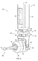
- Figs. 3 and 4 illustrate perspective views of another tool 241 according to various examples.
- the tool 241 is similar to the tool 24 and where the features are similar, the same reference numerals are used. Consequently, the tool 241 includes a first part 28, a second part 30, a joint 32, a conduit 34, a sensor 36, and a rotatable member 38.
- the first part 28 has a first longitudinal axis 43 that extends along the length of the first part 28, and the second part 30 has a second longitudinal axis 45 that extends along the length of the second part 30.
- the second cover 42 has a cylindrical shape and defines an aperture 52 there through (which may also be referred to as a 'window').
- the sensor 36 is positioned within the second cover 42 and adjacent to the aperture 52 to enable the sensor 36 to sense one or more states external to the tool 241.
- the second cover 42 also defines a fluid flow passage 53 there within that extends along the length of the second cover 42 and is arranged to receive fluid (such as air) from a source and to provide the fluid to the conduit 34.
- the second cover 42 defines one or more holes 55 that extend along the length of the second cover 42 and are arranged to receive one or more cables 54 there within.
- the fluid flow passage 53 and the one or more holes 55 are positioned around the perimeter of the second cover 42 which advantageously provides sufficient space within the second cover 42 for the sensor 36.
- the first joint 48 comprises one or more cables 54, a plurality of discs 56 and a plurality of flexible interconnectors 58.
- the one or more cables 54 are coupled to the first part 28 and are moveable relative to the second part 30 to enable the first part 28 to be moved relative to the second part 30.
- the plurality of flexible interconnectors 58 interconnect the discs 56 and enable the discs to pivot relative to one another so that the first part 28 may extend radially outwards from the longitudinal axis 43.
- the plurality of discs 56 define one or more holes that extend through the discs 56 and are arranged to receive the one or more cables 54 there within.
- the one or more cables 54 are slidable within the one or more holes of the second cover 42 and the plurality of discs 56 respectively. In some examples, one or more of the cables 54 may not be directly connected to the first part 28 and may instead be connected to one or more of the discs 56.
- the second joint 50 (not illustrated in Fig. 3 to maintain the clarity of the figure) is a pivot joint and includes a pair of arms 60 that extend towards the first part 28 from the disc 56 that is adjacent to the first part 28.
- the arms 60 are pivotally coupled to the first part 28 via pins 62.
- the first part 28 may be pivoted relative to the second part 30 at the second joint 50 via actuation of the one or more cables 54 so that the first longitudinal axis 43 of the first part 28 extends radially outwards from the longitudinal axis 43 (as illustrated in Fig. 4 ).
- the first cover 40 of the first part 28 has a cylindrical shape and houses the rotatable member 38 that is coupled to the blending tool 46 via the chuck 44.
- the rotatable member 38 includes fluid guide channels 64 and a turbine 66 that is coupled to the chuck 44.
- the fluid guide channels 64 are fixed in position relative to the first cover 40 (that is, the fluid guide channels 64 are a static part within the first cover 40) and are arranged to receive fluid from the conduit 34.
- the turbine 66 is arranged to receive fluid from the fluid guide channels 64 and to rotate about the first longitudinal axis 43 relative to the first cover 40.
- the fluid flow passage in the second cover 42 receives fluid (such as air) from a source (such as a pressurized air container).
- the fluid then flows to the turbine 66 via the conduit 34 and the fluid guide channels 64.
- the flow of fluid through the turbine 66 causes the turbine 66 to rotate about the first longitudinal axis 43 and thus drive the chuck 44 and the machine tool 46 to rotate about the first longitudinal axis 43.
- the tool 24, 241 may provide several advantages.
- the rotatable member 38 may be arranged to rotate at relatively high speed and the tool 24, 241 may consequently require a lower force to machine the object 26.
- the rotatable member 38 includes a turbine (such as the turbine 66)
- the turbine may rotate at 200,000 to 400,000 RPM.
- the inclusion of the sensor 36 may enable an operator of the tool 24, 241 to inspect and measure the object 26 during machining. This may significantly reduce the time required to machine the object 26 relative to the use of a machining tool and separate sensing device.
- the object 26 is a blade within a gas turbine engine and the tool 24, 241 is a blending tool
- use of the tool 24, 241 may reduce the time required to blend the blade by up to fifty times.
- the positioning of the fluid flow passage 53 and the holes 55 may advantageously enable sufficient fluid to be provided to the turbine 66 and enable the sensor 36 to be positioned within the second cover 42. This may advantageously reduce the size of the tool 24, 241 and enable the tool 24, 241 to be inserted into relatively narrow spaces within a mechanical system.
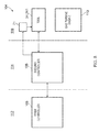
- Fig. 6 illustrates a schematic diagram of apparatus 68 for controlling machining according to various examples.
- the apparatus 68 includes a controller 70, an actuator 71, a user input device 72, an output device 73, and the tool 24, 241.
- the apparatus 68 may be a single, unitary device where the controller 70, the actuator 71, the user input device 72, the output device 73, and the tool 24, 241 are physically coupled together.
- the apparatus 68 may be an apparatus that is distributed across a plurality of different locations (for example, the apparatus 68 may be distributed across different cities, different counties or different countries).
- the apparatus 68 may be a module.
- the wording 'module' refers to a device or apparatus where one or more features are included at a later time, and possibly, by another manufacturer or by an end user.
- the apparatus 68 may only include the controller 70, and the remaining features may be added by another manufacturer, or by an end user.
- the controller 70 may comprise any suitable circuitry to cause performance of the methods described herein and as illustrated in Figs. 7 & 9 .
- the controller 70 may comprise any of, or combination of: application specific integrated circuits (ASIC); field programmable gate arrays (FPGA); single or multi-processor architectures; sequential (Von Neumann)/parallel architectures; programmable logic controllers (PLCs); microprocessors; and microcontrollers, to perform the methods.
- ASIC application specific integrated circuits
- FPGA field programmable gate arrays
- PLCs programmable logic controllers
- microprocessors and microcontrollers, to perform the methods.
- the controller 70 may comprise at least one processor 74 and at least one memory 76.
- the memory 76 stores a computer program 78 comprising computer readable instructions that, when read by the processor 74, causes performance of the methods described herein, and as illustrated in Figs. 7 & 9 .
- the computer program 78 may be software or firmware, or may be a combination of software and firmware.
- the processor 74 may be located on the tool 24, 241, or may be located remote from the tool 24, 241, or may be distributed between the tool 24, 241 and a location remote from the tool 24, 241.
- the processor 74 may include at least one microprocessor and may comprise a single core processor, or may comprise multiple processor cores (such as a dual core processor or a quad core processor).
- the memory 76 may be located on the tool 24, 241, or may be located remote from the tool 24, 241, or may be distributed between the tool 24, 241 and a location remote from the tool 24, 241.
- the memory 76 may be any suitable non-transitory computer readable storage medium, data storage device or devices, and may comprise a hard disk and/or solid state memory (such as flash memory).
- the memory 76 may be permanent non-removable memory, or may be removable memory (such as a universal serial bus (USB) flash drive).
- the computer program 78 may be stored on a non-transitory computer readable storage medium 80.
- the computer program 78 may be transferred from the non-transitory computer readable storage medium 80 to the memory 76.
- the non-transitory computer readable storage medium 80 may be, for example, a USB flash drive, a compact disc (CD), a digital versatile disc (DVD) or a Blu-ray disc.
- the computer program 78 may be transferred to the memory 76 via a wireless signal 82 or via a wired signal 82.
- the actuator 71 may comprise any suitable device or devices for controlling the tool 24, 241.
- the actuator 71 may comprise one or more servomotors that are coupled to the one or more cables 54 of the tool 241 to move the first part 28 relative to the second part 30.
- the actuator 71 may also comprise a fluid source (such as a compressed air container) that is arranged to provide fluid to the fluid flow passages of the second cover 42.
- the controller 70 is configured to provide control signals to the actuator 71 to control the operation of the actuator 71.
- the sensor 36 of the tool 24, 241 is arranged to receive control signals from the controller 70 that control the operation of the sensor 36.
- the controller 70 may be configured to control the optical zoom and/or focal point of the imaging device.
- the sensor 36 is arranged to provide signals to the controller 70 for the sensed state of the tool 24, 241 and/or for the sensed external state of the tool 24, 241.
- the user input device 72 may be any suitable device, or devices, for enabling a user to control the apparatus 68.
- the user input device 72 may comprise one or more of, or any combination of: a keyboard, a keypad, a touchscreen display, a computer mouse, and a touchpad.
- the controller 70 is configured to receive user input control signals from the user input device 72.
- the output device 73 may be any suitable device for presenting information to a user of the apparatus 68.
- the output device 73 may comprise a display (such as a liquid crystal display (LCD), a light emitting diode (LED) display, or a thin film transistor (TFT) display for example).
- the controller 70 may be configured to cause control of the display to display images.
- the controller 70 may receive image data from the sensor 36 of the tool 24, 241 and then cause control of the display of the output device 73 to display an image using the received image data.
- the output device 73 may additionally or alternatively comprise a loudspeaker to provide acoustic waves to the user of the apparatus 68 and the controller 70 may be configured to cause control of the loudspeaker to provide acoustic waves.
- the output device 73 may include an actuator that may be used to rotate a rotor of a gas turbine engine to position the object 26.
- the method starts and a user may mount at least the tool 24, 241 on a mechanical system such as a gas turbine engine.
- the user may initialise the apparatus 68 by operating the user input device 72.
- the user input device 72 includes a power switch
- the user may initialise the apparatus 68 by pressing the power switch to supply electrical energy to the apparatus 68.
- the user may initialise the apparatus 68 by interacting with a graphical user interface displayed on a display of the output device 73 using the user input device 72 to execute the computer program 78.
- the method includes receiving data from the sensor 36 of the tool 24, 241.
- the data may include image data from the sensor 36 for the view out of the aperture 52.
- the controller 70 may receive the data from the sensor 36 and cause control of the output device 73 to present information to the user using the received data.
- the controller 70 may cause control of a display of the output 73 to display the image in the image data.
- the method includes determining whether relative movement between the tool 24, 241 and the object 26 is required to enable machining of the object 26 by the tool 24, 241.
- the controller 70 may analyse image data received in block 86 to determine whether the object 26 to be machined is positioned at a predetermined position and/or orientation relative to the tool 24, 241.
- the controller 70 may analyse data from the ultrasonic sensor to determine whether the object 26 to be machined is positioned at a predetermined position and/or orientation relative to the tool 24, 241.
- the controller 70 determines that the object 26 is not positioned at the predetermined position and/or orientation, the controller 70 determines that relative movement between the tool 24, 241 and the object 26 is required to enable machining of the object 26.
- the controller 70 may then cause control of the output device 73 to present information to the user of the apparatus 68 to inform the user to move the object 26 and/or the tool 24, 241.
- the controller 70 may cause control of the output device 73 to present information to the user to inform the user to move the fan blade or compressor by a certain angle in either the clockwise or anticlockwise direction.
- the controller 70 may provide a control signal to the tool 24, 241 and/or the object 26 to cause the tool 24, 241 and/or the object 26 to move relative to one another (for example, the tool 24, 241 may include robotics that enable the tool 24, 241 to move relative to the object 26 to the predetermined position).
- Block 88 may then be repeated until the controller 70 determines that the object 26 is positioned at the predetermined position and/or orientation relative to the tool 24, 241. Where the controller 70 determines that the object 26 is positioned at the predetermined position and/or orientation relative to the tool 24, 241, the method moves to block 90.
- the method includes determining whether the object 26 has a shape that differs from a predetermined shape to determine whether the object 26 is damaged.
- the memory 76 may store predetermined shapes for one or more different objects.
- the controller 70 may compare the similarity of the sensed shape of the object 26 with the predetermined shape of the object stored in the memory 76 to determine whether the similarity is below a threshold similarity value.
- the controller 70 may compare the differences between the sensed shape of the object 26 and the predetermined shape of the object stored in the memory 76 to determine whether the difference is above a threshold difference value.
- a predetermined shape of the compressor blade may be stored in the memory 76.
- the controller 70 may compare the similarity of the sensed shape of the compressor blade with the predetermined shape of the compressor blade stored in the memory 76 to determine whether the similarity is below a threshold similarity value.
- the method may return to block 86 for another different object. Where no further objects are to be machined, the method moves to block 102 and is ended. Where the controller 70 determines that the shape of the object 26 differs from (or is not similar to) the predetermined shape of the object 26, the method moves to block 92.
- This tool path is then broken into a number of steps to provide an iterative formation of the shape.
- a collision check is then performed using the inverse kinematics of the controller 70 to ascertain if the tool 24, 241 will collide with anything, and if not, the method moves to block 94.
- the controller 70 may store the generated machining path in the memory 76.
- the method includes providing a control signal to cause control of the tool 24, 241.
- the controller 70 may use the machining path generated at block 92 to cause control of the tool 24, 241 to machine the object 26.
- the controller 70 may convert the machining path into a control signal to cause control of the tool 24, 241.
- the controller 70 may directly control the tool 24, 241 to machine the object 26.
- the controller 70 may indirectly control the tool 24, 241 by sending a control signal to one or more other controllers that then directly control the tool 24, 241 (in other words, there may be one or more other controllers in the control path between the controller 70 and the tool 24, 241).
- the method includes determining whether the object 26 has a shape after machining that differs from the predetermined shape.
- the controller 70 may receive data from the sensor 36 of the tool 24, 241 for the machined object 26 and then use that data to determine whether the shape of the object 26 is below a threshold similarity value when compared with the predetermined shape, or may use that data to determine whether the shape of the object 26 is above a threshold difference value when compared with the predetermined shape.
- the method may return to block 86 for another different object. Where no further objects are to be machined, the method moves to block 102 and is ended. Where the controller 70 determines that the shape of the machined object 26 differs from (or is not similar to) the predetermined shape of the object 26, the method moves to block 98.
- the method includes determining a further machining path for the tool 24, 241 to bring the shape of the object 26 further towards conformity with the predetermined shape.
- the method includes providing a control signal to cause control of the tool 24, 241.
- the controller 70 may use the machining path generated at block 98 to cause control of the tool 24, 241 to further machine the object 26.
- the controller 70 may directly control the tool 24, 241 to machine the object 26.
- the controller 70 may indirectly control the tool 24, 241 by sending a control signal to one or more other controllers that then directly control the tool 24, 241.
- the method then returns to block 96 to determine whether the object 26 has a shape after machining that differs from the predetermined shape. Where the controller 70 determines that the shape of the machined object 26 does not differ from (or is similar to) the predetermined shape of the object 26, the method may return to block 86 for another, different object. Where no further objects are to be machined, the method moves to block 102 and is ended. Where the controller 70 determines that the shape of the machined object 26 differs from (or is not similar to) the predetermined shape of the object 26, the method moves to block 98.
- the apparatus 68 may provide several advantages.
- the apparatus 68 may enable a machining operation (such as blending for example) to be performed automatically by the controller 70 and without human intervention. This may enable repair quality to be standardised.
- the output device 73 may advantageously enable an operator to visually inspect the damaged component of the mechanical system during and after machining.
- the second controller 108 may be referred to as a 'low level controller (LLC)' and may comprise a structure as described in the preceding paragraphs for the controller 70.
- the controller 108 may include a tool controller, a graphical user interface (GUI), and a low level control communicator (LLCC) that includes a secure protocol engine and command processor.
- the second controller 108 is located in a second zone 114 and may also be connected to a user input device 72 and an output device 73 as illustrated in Fig. 6 .
- the actuator 71, tool 24, 241 and the mechanical system 110 are located in a third zone 116.
- the mechanical system 110 is a gas turbine engine and may be structured as illustrated in Fig. 1 (in other words, the gas turbine engine may be a three shaft gas turbine engine 10 as illustrated in Fig. 1 ).
- the first zone 112, the second zone 114, and the third zone 116 may represent different locations.
- the first zone 112, the second zone 114, and the third zone 116 may represent different countries, states, counties, or cities.
- the first zone 112 may represent a control centre in a first country
- the second zone 114 may represent a control centre in a second country
- the third zone 116 may represent an aircraft maintenance hangar in the second country.
- the second zone 114 and the third zone 116 may be the same location and consequently, the second controller 108 may be located in closer proximity to the tool 24, 241 than the first controller 106.
- the first zone 112 may represent a control centre in a first country
- the second and third zones 114, 116 may represent an aircraft maintenance hangar in a second country.
- the method includes installation of the tool 24, 241 (referred to as the blending instrument/robot in Fig. 9 ) on the mechanical system 110 by the local operator.
- the tool 24, 241 referred to as the blending instrument/robot in Fig. 9
- the method includes establishing a data connection between the first controller 106 and the second controller 108.
- the method includes calibrating the tool 24, 241.
- the second controller 108 may calibrate the tool 24, 241 using data stored at the second controller 108.
- the method includes obtaining measurements of an object 26 of the mechanical system 110.
- block 124 may include obtaining measurements of a damaged turbine blade of a gas turbine engine.
- Block 124 may be performed by the second controller 108.
- the method includes providing a definition of the desired blend specifications, which may be performed by the first controller 106.
- the method includes generating a blending path, which may be performed by the first controller 106.
- the first controller 106 may receive the measurements from the second controller 108 and then use the received measurements and the blend specification provided in block 126 to generate a blending path.
- the method includes conversion of the blending path to tool motion control signals, which may be performed by the second controller 108.
- the second controller 108 may receive the generated blending path from the first controller 106 and then convert the blending path to tool motion control signals.
- the method includes performing the defined blending operation, which may be performed by the second controller 108, the actuator 71, and the tool 24, 241.
- the second controller 108 may provide the tool motion control signals to the actuator 71 and to the tool 24, 241 to control blending of the damaged turbine blade.
- the method includes measuring the performed blend, which may be performed by the second controller 108.
- the second controller 108 may receive data from the sensor 36 of the tool 24, 241 and use the received data to measure the blend.
- the method includes comparing the performed blend and the desired blend.
- the first controller 106 may receive measurement data from the second controller 108 (determined in block 134) and use the received measurement data to compare the performed blend and the desired blend. Where the performed blend does not match the desired blend, the method returns to block 128 and the first controller 106 generates a new blending path. Where the performed blend matches the desired blend and another object requires blending, the method returns to block 124. Where the performed blend matches the desired blend and no further objects require blending, the method moves to block 138.
- the method includes terminating the connection between the first controller 106 and the second controller 108.
- the method includes uninstalling the tool 24, 241 from the mechanical system 110 by the local operator.
- the apparatus 104 may provide several advantages. For example, there are typically few operators who are sufficiently skilled and experienced to perform blending on internal components of a gas turbine engine.
- the apparatus 104 may advantageously enable such operators to monitor and/or control blending remotely (for example, through interaction with the first controller 106) and without being required to travel to the gas turbine engine.
- the operator may remain in the first zone 112 and monitor and/or control blending of damaged gas turbine engine components in other zones (such as the third zone 116). This may advantageously enable the operator to repair a greater number of components and may also advantageously reduce the cost of blending operations (since the operator may spend less time and money on travelling).
- the tool 24, 241 may not include a rotatable member and machine head and may instead include one or more of: a laser head, an imaging sensor (for example, a charge coupled device camera), a Raman spectrometer, a fluorescent penetrant applicator, and an ultraviolet (UV) inspection device.
- a laser head for example, a charge coupled device camera
- a Raman spectrometer for example, a Raman spectrometer
- a fluorescent penetrant applicator for example, a fluorescent penetrant applicator
- UV ultraviolet
Landscapes
- Engineering & Computer Science (AREA)
- Mechanical Engineering (AREA)
- Physics & Mathematics (AREA)
- General Engineering & Computer Science (AREA)
- Human Computer Interaction (AREA)
- Manufacturing & Machinery (AREA)
- General Physics & Mathematics (AREA)
- Automation & Control Theory (AREA)
- Optics & Photonics (AREA)
- Numerical Control (AREA)
- Grinding And Polishing Of Tertiary Curved Surfaces And Surfaces With Complex Shapes (AREA)
Abstract
Description
- The present disclosure concerns a tool for machining an object.
- Gas turbine engines may be used, for example, to propel aircraft and/or to generate electrical energy.
Fig. 1 illustrates an example of agas turbine engine 10 having a principal androtational axis 11. Theengine 10 comprises, in axial flow series, anair intake 12, apropulsive fan 13, anintermediate pressure compressor 14, a high-pressure compressor 15,combustion equipment 16, a high-pressure turbine 17, andintermediate pressure turbine 18, a low-pressure turbine 19 and anexhaust nozzle 20. Anacelle 21 generally surrounds theengine 10 and defines both theintake 12 and theexhaust nozzle 20. - The
gas turbine engine 10 works in the conventional manner so that air entering theintake 12 is accelerated by thefan 13 to produce two air flows: a first air flow into theintermediate pressure compressor 14 and a second air flow which passes through abypass duct 22 to provide propulsive thrust. Theintermediate pressure compressor 14 compresses the air flow directed into it before delivering that air to thehigh pressure compressor 15 where further compression takes place. - The compressed air exhausted from the high-
pressure compressor 15 is directed into thecombustion equipment 16 where it is mixed with fuel and the mixture combusted. The resultant hot combustion products then expand through, and thereby drive the high, intermediate and low-pressure turbines nozzle 20 to provide additional propulsive thrust. The high 17, intermediate 18 and low 19 pressure turbines drive respectively thehigh pressure compressor 15,intermediate pressure compressor 14 andfan 13, each by suitable interconnecting shaft. - Gas turbine engines may require maintenance and repair during their operational life. For example, a fan blade or a compressor blade of a gas turbine engine may become damaged during operation (for example, the fan or compressor blade may become chipped) and such damage may impair the performance of the gas turbine engine. A highly skilled engineer may be required to perform the repair. However, such repair may be costly and/or may not be performed in a timely manner where the gas turbine engine is located remote from a repair centre.
- According to various, but not necessarily all, embodiments of the invention there is provided a tool for machining an object, the tool comprising: a first part including a rotatable member, the rotatable member being rotatable to cause rotation of a machine tool; a second part; a joint coupling the first part and the second part to enable relative movement between the first part and the second part; and a sensor to sense an object to be machined.
- The sensor may be configured to provide image data and/or measurement data of the object to be machined.
- The second part may comprise the sensor.
- The second part may comprise a cover defining an aperture. The sensor may be positioned within the cover and adjacent to the aperture.
- The tool may further comprise an energy transmission member extending between the first part and the second part and across the joint. The energy transmission member may be arranged to provide energy to the rotatable member to cause rotation of the rotatable member.
- The energy transmission member may comprise a conduit to provide fluid to the rotatable member.
- The energy transmission member may comprise an electrical cable to provide electrical energy to the rotatable member.
- The rotatable member may comprise a turbine.
- The rotatable member may comprise an electrical motor.
- The joint may comprise one or more cables coupled to the first part. The one or more cables may be moveable relative to the second part to enable the first part to be moved relative to the second part.
- The tool may further comprise a machine tool coupled to the rotatable member to receive torque from the rotatable member.
- The machine tool may comprise a blending tool.
- According to various, but not necessarily all, embodiments of the invention there is provided apparatus comprising: a controller to: receive data from the sensor of a tool; determine control of the tool using the received data; and provide a control signal to cause control of the tool. In some embodiments, the tool may be structured as described in any of the preceding paragraphs. In other embodiments, the tool may have an alternative structure and may be an inspection apparatus and include, for example, a Raman spectrometer, an imaging device (such as a camera) or an Ultraviolet (UV) inspection device.
- The controller may be to determine whether relative movement between the tool and the object is required to enable machining of the object by the tool.
- The controller may be to determine control of the tool by: determining whether the object has a shape that differs from a predetermined shape above a threshold level; and determining a machining path for the tool to bring the shape of the object at least towards conformity with the predetermined shape.
- The controller may be to determine whether the object has a shape after machining that differs from the predetermined shape above a threshold level; and determining a further machining path for the tool to bring the shape of the object further towards conformity with the predetermined shape.
- The controller may be configured to operate without user intervention.
- The controller may comprise a first controller and a second controller. The first controller may be to determine the control of the tool. The second controller may be to provide the control signal to the tool to control the apparatus. The first controller may communicate with multiple second controllers at a time in a multi-device configuration.
- The second controller may be located in closer proximity to the tool than the first controller.
- The first controller may be configured to receive data from the sensor. The first controller may be configured to provide the data to the second controller. The second controller may be configured to determine a machining path for the tool.
- The second controller may be to receive the machining path from the first controller. The second controller may be to convert the machining path into control signals to control the tool.
- The apparatus may further comprise an actuator to receive the control signals from the controller and to control the tool using the control signals.
- According to various, but not necessarily all, embodiments of the invention there is provided a method comprising: receiving data from the sensor of the tool as described in any of the preceding paragraphs; determining control of the tool using the received data; and providing a control signal to cause control of the tool.
- The method may further comprise determining whether relative movement between the tool and the object is required to enable machining of the object by the tool.
- Determining control of the tool may include determining whether the object has a shape that differs from a predetermined shape; and determining a machining path for the tool to bring the shape of the object at least towards conformity with the predetermined shape where it is determined that the shape of the object differs from the predetermined shape.
- The method may further comprise determining whether the object has a shape after machining that differs from the predetermined shape; and determining a further machining path for the tool to bring the shape of the object further towards conformity with the predetermined shape where it is determined that the machined shape of the object differs from the predetermined shape.
- The method may be performed without user intervention.
- According to various, but not necessarily all, embodiments of the invention, there is provided a computer program that, when read by a computer, causes performance of the method as described in any of the preceding paragraphs.
- According to various, but not necessarily all, embodiments of the invention there is provided a non-transitory computer readable storage medium comprising computer readable instructions that, when read by a computer, causes performance of the method as described in any of the preceding paragraphs.
- The skilled person will appreciate that except where mutually exclusive, a feature described in relation to any one of the above aspects may be applied mutatis mutandis to any other aspect.
- Examples will now be described with reference to the Figures, in which:
-
Fig. 1 illustrates a cross sectional side view of a gas turbine engine; -
Fig. 2 illustrates a schematic diagram of a tool according to various examples; -
Fig. 3 illustrates a sectional perspective view of a tool according to various examples; -
Fig. 4 illustrates a perspective view of the exterior of the tool illustrated inFig. 3 ; -
Fig. 5 illustrates a perspective view of second part of the tool illustrated inFigs. 3 and4 ; -
Fig. 6 illustrates a schematic diagram of apparatus for controlling machining according to various examples; -
Fig. 7 illustrates a flow diagram of a method of controlling machining according to various examples; -
Fig. 8 illustrates a schematic diagram of another apparatus for controlling machining according to various examples; and -
Fig. 9 illustrates a flow diagram of another method of controlling machining according to various examples. - In the following description, the terms 'connected' and 'coupled' mean operationally connected and coupled. It should be appreciated that there may be any number of intervening components between the mentioned features, including no intervening components.
-
Fig. 2 illustrates a schematic diagram of atool 24 for machining anobject 26. Thetool 24 may be any suitable apparatus or device for machining theobject 26. For example, thetool 24 may be any suitable rotary machine tool, and may be, for example, a blending tool, a grinding tool, or a drilling tool. Thetool 24 includes afirst part 28, asecond part 30, a joint 32, an (optional)energy transmission member 34, asensor 36, and arotatable member 38 to cause rotation of a machine tool. Theobject 26 may be any object to be machined. For example, theobject 26 may be a component of a gas turbine engine, and may be a blade or a vane of a gas turbine engine. - The
first part 28 includes therotatable member 38 and may include afirst cover 40 for at least partially covering therotatable member 38. Thefirst cover 40 may have any suitable shape and define a cavity for receiving therotatable member 38 therein. For example, thefirst cover 40 may have a circular cross sectional shape, an elliptical cross sectional shape, a square cross sectional shape or a rectangular cross sectional shape. - The
second part 30 may include asecond cover 42 for at least partially covering one or more components of thetool 24. Thesecond cover 42 may have any suitable shape and define a cavity for receiving the one or more components therein. For example, thesecond cover 42 may have a circular cross sectional shape, an elliptical cross sectional shape, a square cross sectional shape, or a rectangular cross sectional shape. - The joint 32 is arranged to couple the
first part 28 and thesecond part 30 to enable relative movement between thefirst part 28 and thesecond part 30. The joint 32 may comprise any suitable structure and may comprise, for example, a pivot joint, a hinge, or a resilient material interconnecting thefirst part 28 and thesecond part 30. In some examples, the joint 32 may comprise a plurality of joints that may have the same structure or a different structure to one another. - The
rotatable member 38 may be any suitable apparatus or device to cause rotation of a machine tool (such as a blending tool). For example, therotatable member 38 may include a turbine or an electrical motor. Therotatable member 38 may include, or be coupled to, a chuck for receiving a machine tool to provide torque to the machine tool. - The
energy transmission member 34 extends between thefirst part 28 and thesecond part 30 and across the joint 32. Theenergy transmission member 34 is arranged to provide energy to therotatable member 38 to cause rotation of therotatable member 38. For example, where therotatable member 38 comprises a turbine, theenergy transmission member 34 may comprise a conduit to provide fluid to theturbine 38 to cause rotation of therotatable member 38. By way of another example, where therotatable member 38 is an electrical motor, theenergy transmission member 34 may comprise one or more electrical cables to provide electrical energy to theelectrical motor 38. - The
sensor 36 may comprise any suitable sensor, or plurality of sensors, to sense theobject 26 to be machined. Thesensor 36 may comprise one or more sensors (such as one or more of, or any combination of: tachometers, inertial measurement units (IMU), inertial navigation systems (INS), encoders, torque meters, shape sensors, accelerometers) to sense one or more states of thetool 24, such as orientation, position, shape, velocity, acceleration, torque, and so on. Thesensor 36 may additionally or alternatively comprise one or more sensors (such as one or more of, or any combination of: force sensors, strain gauges, pressure sensors, bending sensors, proximity sensors, imaging sensors, temperature sensors, humidity sensors, radiation detection sensors and so on) to sense one or more states external to thetool 24, such as force, strain, pressure, bend temperature, humidity, radiation, distance to an external object, size of an external object, material of an external object, and shape and orientation of an external object. - In some examples, the
sensor 36 may be at least partially positioned within thesecond cover 42 of thesecond part 30. In such examples, thesecond cover 42 may define an aperture and thesensor 36 may be positioned adjacent the aperture to enable thesensor 36 to sense one or more states external to thetool 24. -
Figs. 3 and4 illustrate perspective views of anothertool 241 according to various examples. Thetool 241 is similar to thetool 24 and where the features are similar, the same reference numerals are used. Consequently, thetool 241 includes afirst part 28, asecond part 30, a joint 32, aconduit 34, asensor 36, and arotatable member 38. Thefirst part 28 has a firstlongitudinal axis 43 that extends along the length of thefirst part 28, and thesecond part 30 has a secondlongitudinal axis 45 that extends along the length of thesecond part 30. - The
tool 241 differs from thetool 24 in that thefirst part 40 further comprises achuck 44 and ablending tool 46. Additionally, the joint 32 includes a first joint 48 (a cable pull joint in this example) and a second joint 50 (a pivot joint in this example). - The
second cover 42 has a cylindrical shape and defines anaperture 52 there through (which may also be referred to as a 'window'). Thesensor 36 is positioned within thesecond cover 42 and adjacent to theaperture 52 to enable thesensor 36 to sense one or more states external to thetool 241. As illustrated inFig. 5 , thesecond cover 42 also defines afluid flow passage 53 there within that extends along the length of thesecond cover 42 and is arranged to receive fluid (such as air) from a source and to provide the fluid to theconduit 34. Additionally, thesecond cover 42 defines one ormore holes 55 that extend along the length of thesecond cover 42 and are arranged to receive one ormore cables 54 there within. Thefluid flow passage 53 and the one ormore holes 55 are positioned around the perimeter of thesecond cover 42 which advantageously provides sufficient space within thesecond cover 42 for thesensor 36. - The first joint 48 comprises one or
more cables 54, a plurality ofdiscs 56 and a plurality offlexible interconnectors 58. The one ormore cables 54 are coupled to thefirst part 28 and are moveable relative to thesecond part 30 to enable thefirst part 28 to be moved relative to thesecond part 30. The plurality offlexible interconnectors 58 interconnect thediscs 56 and enable the discs to pivot relative to one another so that thefirst part 28 may extend radially outwards from thelongitudinal axis 43. The plurality ofdiscs 56 define one or more holes that extend through thediscs 56 and are arranged to receive the one ormore cables 54 there within. The one ormore cables 54 are slidable within the one or more holes of thesecond cover 42 and the plurality ofdiscs 56 respectively. In some examples, one or more of thecables 54 may not be directly connected to thefirst part 28 and may instead be connected to one or more of thediscs 56. - The second joint 50 (not illustrated in
Fig. 3 to maintain the clarity of the figure) is a pivot joint and includes a pair ofarms 60 that extend towards thefirst part 28 from thedisc 56 that is adjacent to thefirst part 28. Thearms 60 are pivotally coupled to thefirst part 28 via pins 62. Thefirst part 28 may be pivoted relative to thesecond part 30 at the second joint 50 via actuation of the one ormore cables 54 so that the firstlongitudinal axis 43 of thefirst part 28 extends radially outwards from the longitudinal axis 43 (as illustrated inFig. 4 ). - The
first cover 40 of thefirst part 28 has a cylindrical shape and houses therotatable member 38 that is coupled to theblending tool 46 via thechuck 44. Therotatable member 38 includesfluid guide channels 64 and aturbine 66 that is coupled to thechuck 44. Thefluid guide channels 64 are fixed in position relative to the first cover 40 (that is, thefluid guide channels 64 are a static part within the first cover 40) and are arranged to receive fluid from theconduit 34. Theturbine 66 is arranged to receive fluid from thefluid guide channels 64 and to rotate about the firstlongitudinal axis 43 relative to thefirst cover 40. - In operation, the fluid flow passage in the
second cover 42 receives fluid (such as air) from a source (such as a pressurized air container). The fluid then flows to theturbine 66 via theconduit 34 and thefluid guide channels 64. The flow of fluid through theturbine 66 causes theturbine 66 to rotate about the firstlongitudinal axis 43 and thus drive thechuck 44 and themachine tool 46 to rotate about the firstlongitudinal axis 43. - The
tool rotatable member 38 may be arranged to rotate at relatively high speed and thetool object 26. For example, where therotatable member 38 includes a turbine (such as the turbine 66), the turbine may rotate at 200,000 to 400,000 RPM. Second, the inclusion of thesensor 36 may enable an operator of thetool object 26 during machining. This may significantly reduce the time required to machine theobject 26 relative to the use of a machining tool and separate sensing device. For example, where theobject 26 is a blade within a gas turbine engine and thetool tool fluid flow passage 53 and theholes 55 may advantageously enable sufficient fluid to be provided to theturbine 66 and enable thesensor 36 to be positioned within thesecond cover 42. This may advantageously reduce the size of thetool tool -
Fig. 6 illustrates a schematic diagram ofapparatus 68 for controlling machining according to various examples. Theapparatus 68 includes acontroller 70, anactuator 71, auser input device 72, anoutput device 73, and thetool apparatus 68 may be a single, unitary device where thecontroller 70, theactuator 71, theuser input device 72, theoutput device 73, and thetool apparatus 68 may be an apparatus that is distributed across a plurality of different locations (for example, theapparatus 68 may be distributed across different cities, different counties or different countries). - In some examples, the
apparatus 68 may be a module. As used herein, the wording 'module' refers to a device or apparatus where one or more features are included at a later time, and possibly, by another manufacturer or by an end user. For example, where theapparatus 68 is a module, theapparatus 68 may only include thecontroller 70, and the remaining features may be added by another manufacturer, or by an end user. - The
controller 70 may comprise any suitable circuitry to cause performance of the methods described herein and as illustrated inFigs. 7 &9 . Thecontroller 70 may comprise any of, or combination of: application specific integrated circuits (ASIC); field programmable gate arrays (FPGA); single or multi-processor architectures; sequential (Von Neumann)/parallel architectures; programmable logic controllers (PLCs); microprocessors; and microcontrollers, to perform the methods. - By way of an example, the
controller 70 may comprise at least oneprocessor 74 and at least onememory 76. Thememory 76 stores acomputer program 78 comprising computer readable instructions that, when read by theprocessor 74, causes performance of the methods described herein, and as illustrated inFigs. 7 &9 . Thecomputer program 78 may be software or firmware, or may be a combination of software and firmware. - The
processor 74 may be located on thetool tool tool tool processor 74 may include at least one microprocessor and may comprise a single core processor, or may comprise multiple processor cores (such as a dual core processor or a quad core processor). - The
memory 76 may be located on thetool tool tool tool memory 76 may be any suitable non-transitory computer readable storage medium, data storage device or devices, and may comprise a hard disk and/or solid state memory (such as flash memory). Thememory 76 may be permanent non-removable memory, or may be removable memory (such as a universal serial bus (USB) flash drive). - The
computer program 78 may be stored on a non-transitory computerreadable storage medium 80. Thecomputer program 78 may be transferred from the non-transitory computerreadable storage medium 80 to thememory 76. The non-transitory computerreadable storage medium 80 may be, for example, a USB flash drive, a compact disc (CD), a digital versatile disc (DVD) or a Blu-ray disc. In some examples, thecomputer program 78 may be transferred to thememory 76 via awireless signal 82 or via awired signal 82. - The
actuator 71 may comprise any suitable device or devices for controlling thetool actuator 71 may comprise one or more servomotors that are coupled to the one ormore cables 54 of thetool 241 to move thefirst part 28 relative to thesecond part 30. Theactuator 71 may also comprise a fluid source (such as a compressed air container) that is arranged to provide fluid to the fluid flow passages of thesecond cover 42. Thecontroller 70 is configured to provide control signals to theactuator 71 to control the operation of theactuator 71. - The
sensor 36 of thetool controller 70 that control the operation of thesensor 36. For example, where thesensor 36 includes an imaging device (such as a CCD or CMOS camera), thecontroller 70 may be configured to control the optical zoom and/or focal point of the imaging device. Thesensor 36 is arranged to provide signals to thecontroller 70 for the sensed state of thetool tool - The
user input device 72 may be any suitable device, or devices, for enabling a user to control theapparatus 68. For example, theuser input device 72 may comprise one or more of, or any combination of: a keyboard, a keypad, a touchscreen display, a computer mouse, and a touchpad. Thecontroller 70 is configured to receive user input control signals from theuser input device 72. - The
output device 73 may be any suitable device for presenting information to a user of theapparatus 68. Theoutput device 73 may comprise a display (such as a liquid crystal display (LCD), a light emitting diode (LED) display, or a thin film transistor (TFT) display for example). Thecontroller 70 may be configured to cause control of the display to display images. For example, thecontroller 70 may receive image data from thesensor 36 of thetool output device 73 to display an image using the received image data. Theoutput device 73 may additionally or alternatively comprise a loudspeaker to provide acoustic waves to the user of theapparatus 68 and thecontroller 70 may be configured to cause control of the loudspeaker to provide acoustic waves. In some examples, theoutput device 73 may include an actuator that may be used to rotate a rotor of a gas turbine engine to position theobject 26. - The operation of the
apparatus 68 is described in the following paragraphs with reference toFig. 7 . - At
block 84, the method starts and a user may mount at least thetool apparatus 68 by operating theuser input device 72. For example, where theuser input device 72 includes a power switch, the user may initialise theapparatus 68 by pressing the power switch to supply electrical energy to theapparatus 68. By way of another example, the user may initialise theapparatus 68 by interacting with a graphical user interface displayed on a display of theoutput device 73 using theuser input device 72 to execute thecomputer program 78. - At
block 86, the method includes receiving data from thesensor 36 of thetool sensor 36 for the view out of theaperture 52. Thecontroller 70 may receive the data from thesensor 36 and cause control of theoutput device 73 to present information to the user using the received data. For example, where thecontroller 70 receives image data from thesensor 36, thecontroller 70 may cause control of a display of theoutput 73 to display the image in the image data. - At
block 88, the method includes determining whether relative movement between thetool object 26 is required to enable machining of theobject 26 by thetool controller 70 may analyse image data received inblock 86 to determine whether theobject 26 to be machined is positioned at a predetermined position and/or orientation relative to thetool sensor 36 includes an ultrasonic sensor for transmitting and sensing ultrasonic acoustic waves, thecontroller 70 may analyse data from the ultrasonic sensor to determine whether theobject 26 to be machined is positioned at a predetermined position and/or orientation relative to thetool - Where the
controller 70 determines that theobject 26 is not positioned at the predetermined position and/or orientation, thecontroller 70 determines that relative movement between thetool object 26 is required to enable machining of theobject 26. Thecontroller 70 may then cause control of theoutput device 73 to present information to the user of theapparatus 68 to inform the user to move theobject 26 and/or thetool object 26 is a fan blade or a compressor blade, thecontroller 70 may cause control of theoutput device 73 to present information to the user to inform the user to move the fan blade or compressor by a certain angle in either the clockwise or anticlockwise direction. In some examples, thecontroller 70 may provide a control signal to thetool object 26 to cause thetool object 26 to move relative to one another (for example, thetool tool object 26 to the predetermined position). -
Block 88 may then be repeated until thecontroller 70 determines that theobject 26 is positioned at the predetermined position and/or orientation relative to thetool controller 70 determines that theobject 26 is positioned at the predetermined position and/or orientation relative to thetool - At
block 90, the method includes determining whether theobject 26 has a shape that differs from a predetermined shape to determine whether theobject 26 is damaged. Thememory 76 may store predetermined shapes for one or more different objects. In some examples, thecontroller 70 may compare the similarity of the sensed shape of theobject 26 with the predetermined shape of the object stored in thememory 76 to determine whether the similarity is below a threshold similarity value. By way of another example, thecontroller 70 may compare the differences between the sensed shape of theobject 26 and the predetermined shape of the object stored in thememory 76 to determine whether the difference is above a threshold difference value. - For example, a predetermined shape of the compressor blade may be stored in the
memory 76. Thecontroller 70 may compare the similarity of the sensed shape of the compressor blade with the predetermined shape of the compressor blade stored in thememory 76 to determine whether the similarity is below a threshold similarity value. - Where the
controller 70 determines that the shape of theobject 26 does not differ from (or is similar to) the predetermined shape of theobject 26, the method may return to block 86 for another different object. Where no further objects are to be machined, the method moves to block 102 and is ended. Where thecontroller 70 determines that the shape of theobject 26 differs from (or is not similar to) the predetermined shape of theobject 26, the method moves to block 92. - At
block 92, the method includes determining a machining path for thetool object 26 at least towards conformity with the predetermined shape. In some examples, the determined machining path for thetool object 26 into full conformity with the predetermined shape (that is, so that they have the same shape after machining). According to various examples, a machining path may be determined by generating a surface from the damaged site using the sensor 36 (for example, by creating a mesh from point cloud data). Then, using a preset scallop geometry (one of either a tip blend, or a normal scallop blend), a tool path is matched to the size required by the user. This tool path is then broken into a number of steps to provide an iterative formation of the shape. A collision check is then performed using the inverse kinematics of thecontroller 70 to ascertain if thetool controller 70 may store the generated machining path in thememory 76. - At
block 94, the method includes providing a control signal to cause control of thetool controller 70 may use the machining path generated atblock 92 to cause control of thetool object 26. For example, thecontroller 70 may convert the machining path into a control signal to cause control of thetool controller 70 may directly control thetool object 26. In other examples, thecontroller 70 may indirectly control thetool tool 24, 241 (in other words, there may be one or more other controllers in the control path between thecontroller 70 and thetool 24, 241). - At
block 96, the method includes determining whether theobject 26 has a shape after machining that differs from the predetermined shape. For example, thecontroller 70 may receive data from thesensor 36 of thetool object 26 and then use that data to determine whether the shape of theobject 26 is below a threshold similarity value when compared with the predetermined shape, or may use that data to determine whether the shape of theobject 26 is above a threshold difference value when compared with the predetermined shape. - Where the
controller 70 determines that the shape of the machinedobject 26 does not differ from (or is similar to) the predetermined shape of theobject 26, the method may return to block 86 for another different object. Where no further objects are to be machined, the method moves to block 102 and is ended. Where thecontroller 70 determines that the shape of the machinedobject 26 differs from (or is not similar to) the predetermined shape of theobject 26, the method moves to block 98. - At
block 98, the method includes determining a further machining path for thetool object 26 further towards conformity with the predetermined shape. - At
block 100, the method includes providing a control signal to cause control of thetool controller 70 may use the machining path generated atblock 98 to cause control of thetool object 26. In some examples, thecontroller 70 may directly control thetool object 26. In other examples, thecontroller 70 may indirectly control thetool tool - The method then returns to block 96 to determine whether the
object 26 has a shape after machining that differs from the predetermined shape. Where thecontroller 70 determines that the shape of the machinedobject 26 does not differ from (or is similar to) the predetermined shape of theobject 26, the method may return to block 86 for another, different object. Where no further objects are to be machined, the method moves to block 102 and is ended. Where thecontroller 70 determines that the shape of the machinedobject 26 differs from (or is not similar to) the predetermined shape of theobject 26, the method moves to block 98. - The
apparatus 68 may provide several advantages. For example, theapparatus 68 may enable a machining operation (such as blending for example) to be performed automatically by thecontroller 70 and without human intervention. This may enable repair quality to be standardised. Additionally, theoutput device 73 may advantageously enable an operator to visually inspect the damaged component of the mechanical system during and after machining. -
Fig. 8 illustrates a schematic diagram of anotherapparatus 104 for controlling machining according to various examples. Theapparatus 104 includes afirst controller 106, asecond controller 108, theactuator 71, thetool mechanical system 110. Theapparatus 104 is similar to theapparatus 68 illustrated inFig. 6 and where the features are similar, the same reference numerals are used. - The
first controller 106 may be referred to as a 'high level controller (HLC)' and may comprise a structure as described in the preceding paragraphs for thecontroller 70. Thecontroller 106 may include a virtual reality simulator (VRS), a graphical user interface (GUI), a database, and a high level control communicator (HLCC) that includes a secure protocol engine and command processor. Thefirst controller 106 is located in afirst zone 112 and may also be connected to auser input device 72 and anoutput device 73 as illustrated inFig. 6 . - The
second controller 108 may be referred to as a 'low level controller (LLC)' and may comprise a structure as described in the preceding paragraphs for thecontroller 70. Thecontroller 108 may include a tool controller, a graphical user interface (GUI), and a low level control communicator (LLCC) that includes a secure protocol engine and command processor. Thesecond controller 108 is located in asecond zone 114 and may also be connected to auser input device 72 and anoutput device 73 as illustrated inFig. 6 . - The
actuator 71,tool mechanical system 110 are located in athird zone 116. In some examples, themechanical system 110 is a gas turbine engine and may be structured as illustrated inFig. 1 (in other words, the gas turbine engine may be a three shaftgas turbine engine 10 as illustrated inFig. 1 ). - The
first controller 106, thesecond controller 108, theactuator 71 and thetool first controller 106 and thesecond controller 108 may be coupled to one another via a wired connection (for example, via intercontinental data cables) or via a wireless connection (for example, via a satellite connection). By way of another example, thesecond controller 108 and thetool - The
first zone 112, thesecond zone 114, and thethird zone 116 may represent different locations. For example, thefirst zone 112, thesecond zone 114, and thethird zone 116 may represent different countries, states, counties, or cities. By way of an example, thefirst zone 112 may represent a control centre in a first country, thesecond zone 114 may represent a control centre in a second country, and thethird zone 116 may represent an aircraft maintenance hangar in the second country. In some examples, thesecond zone 114 and thethird zone 116 may be the same location and consequently, thesecond controller 108 may be located in closer proximity to thetool first controller 106. For example, thefirst zone 112 may represent a control centre in a first country, and the second andthird zones - The operation of the
apparatus 104 is described in the following paragraphs with reference toFig. 9 . - At block 118, the method includes installation of the
tool 24, 241 (referred to as the blending instrument/robot inFig. 9 ) on themechanical system 110 by the local operator. - At
block 120, the method includes establishing a data connection between thefirst controller 106 and thesecond controller 108. - At
block 122, the method includes calibrating thetool second controller 108 may calibrate thetool second controller 108. - At
block 124, the method includes obtaining measurements of anobject 26 of themechanical system 110. For example, block 124 may include obtaining measurements of a damaged turbine blade of a gas turbine engine.Block 124 may be performed by thesecond controller 108. - At
block 126, the method includes providing a definition of the desired blend specifications, which may be performed by thefirst controller 106. - At
block 128, the method includes generating a blending path, which may be performed by thefirst controller 106. For example, thefirst controller 106 may receive the measurements from thesecond controller 108 and then use the received measurements and the blend specification provided inblock 126 to generate a blending path. - At
block 130, the method includes conversion of the blending path to tool motion control signals, which may be performed by thesecond controller 108. For example, thesecond controller 108 may receive the generated blending path from thefirst controller 106 and then convert the blending path to tool motion control signals. - At
block 132, the method includes performing the defined blending operation, which may be performed by thesecond controller 108, theactuator 71, and thetool second controller 108 may provide the tool motion control signals to theactuator 71 and to thetool - At
block 134, the method includes measuring the performed blend, which may be performed by thesecond controller 108. For example, thesecond controller 108 may receive data from thesensor 36 of thetool - At
block 136, the method includes comparing the performed blend and the desired blend. For example, thefirst controller 106 may receive measurement data from the second controller 108 (determined in block 134) and use the received measurement data to compare the performed blend and the desired blend. Where the performed blend does not match the desired blend, the method returns to block 128 and thefirst controller 106 generates a new blending path. Where the performed blend matches the desired blend and another object requires blending, the method returns to block 124. Where the performed blend matches the desired blend and no further objects require blending, the method moves to block 138. - At
block 138, the method includes terminating the connection between thefirst controller 106 and thesecond controller 108. - At
block 140, the method includes uninstalling thetool mechanical system 110 by the local operator. - The
apparatus 104 may provide several advantages. For example, there are typically few operators who are sufficiently skilled and experienced to perform blending on internal components of a gas turbine engine. Theapparatus 104 may advantageously enable such operators to monitor and/or control blending remotely (for example, through interaction with the first controller 106) and without being required to travel to the gas turbine engine. In other words, the operator may remain in thefirst zone 112 and monitor and/or control blending of damaged gas turbine engine components in other zones (such as the third zone 116). This may advantageously enable the operator to repair a greater number of components and may also advantageously reduce the cost of blending operations (since the operator may spend less time and money on travelling). - It will be understood that the invention is not limited to the embodiments above-described and various modifications and improvements can be made without departing from the concepts described herein. For example, the
tool - Except where mutually exclusive, any of the features may be employed separately or in combination with any other features and the disclosure extends to and includes all combinations and sub-combinations of one or more features described herein.
Claims (15)
- A tool for machining an object, the tool comprising:a first part including a rotatable member, the rotatable member being rotatable to cause rotation of a machine tool;a second part;a joint coupling the first part and the second part to enable relative movement between the first part and the second part; anda sensor to sense an object to be machined.
- A tool as claimed in claim 1, wherein the sensor is configured to provide image data and/or measurement data of the object to be machined.
- A tool as claimed in claim 1 or 2, wherein the second part comprises: the sensor and a cover defining an aperture, the sensor being positioned within the cover and adjacent to the aperture.
- A tool as claimed in any of the preceding claims, further comprising an energy transmission member extending between the first part and the second part and across the joint, the energy transmission member being arranged to provide energy to the rotatable member to cause rotation of the rotatable member.
- A tool as claimed in claim 4, wherein the rotatable member comprises a turbine and the energy transmission member comprises a conduit to provide fluid to the turbine.
- A tool as claimed in any of the preceding claims, wherein the joint comprises one or more cables coupled to the first part, the one or more cables being moveable relative to the second part to enable the first part to be moved relative to the second part.
- A tool as claimed in any of the preceding claims, further comprising a machine tool coupled to the rotatable member to receive torque from the rotatable member.
- Apparatus for controlling machining, the apparatus comprising:a controller to:receive data from the sensor of the tool as claimed in any of the preceding claims;determine control of the tool using the received data; andprovide a control signal to cause control of the tool.
- Apparatus as claimed in claim 8, wherein the controller is to determine whether relative movement between the tool and the object is required to enable machining of the object by the tool.
- Apparatus as claimed in claim 8 or 9, wherein the controller is to determine control of the tool by: determining whether the object has a shape that differs from a predetermined shape above a threshold level; and determining a machining path for the tool to bring the shape of the object at least towards conformity with the predetermined shape.
- Apparatus as claimed in claim 10, wherein the controller is to determine whether the object has a shape after machining that differs from the predetermined shape above a threshold level; and determining a further machining path for the tool to bring the shape of the object further towards conformity with the predetermined shape.
- Apparatus as claimed in any of claims 8 to 11, wherein the controller comprises a first controller and a second controller, the first controller is to determine the control of the tool, and the second controller is to provide the control signal to the tool to control the apparatus.
- Apparatus as claimed in claim 12, wherein the second controller is located in closer proximity to the tool than the first controller.
- Apparatus as claimed in claim 12 or 13, wherein the first controller is to receive data from the sensor and to provide the data to the second controller, the second controller to determine a machining path for the tool.
- Apparatus as claimed in claim 14, wherein the second controller is to receive the machining path from the first controller and to convert the machining path into control signals to control the tool.
Applications Claiming Priority (1)
| Application Number | Priority Date | Filing Date | Title |
|---|---|---|---|
| GB201503683A GB201503683D0 (en) | 2015-03-05 | 2015-03-05 | A tool for machining an object |
Publications (2)
| Publication Number | Publication Date |
|---|---|
| EP3064315A1 true EP3064315A1 (en) | 2016-09-07 |
| EP3064315B1 EP3064315B1 (en) | 2023-06-07 |
Family
ID=52998389
Family Applications (1)
| Application Number | Title | Priority Date | Filing Date |
|---|---|---|---|
| EP16156884.5A Active EP3064315B1 (en) | 2015-03-05 | 2016-02-23 | Tool for machining an object and apparatus for controlling machining |
Country Status (4)
| Country | Link |
|---|---|
| US (2) | US10345785B2 (en) |
| EP (1) | EP3064315B1 (en) |
| GB (2) | GB201503683D0 (en) |
| SG (1) | SG10201601483RA (en) |
Cited By (2)
| Publication number | Priority date | Publication date | Assignee | Title |
|---|---|---|---|---|
| GB2549308A (en) * | 2016-04-13 | 2017-10-18 | Rolls Royce Plc | Apparatus for machining components of gas turbine engines |
| EP3588218A1 (en) * | 2018-06-25 | 2020-01-01 | Siemens Aktiengesellschaft | Method for machining a workpiece for producing a hot gas part |
Families Citing this family (3)
| Publication number | Priority date | Publication date | Assignee | Title |
|---|---|---|---|---|
| US10589428B1 (en) * | 2015-10-01 | 2020-03-17 | Verily Life Sciences Llc | Automatic distribution of control functions between multiple knob controllers based on proximity and relative positioning of the knobs |
| KR20230132494A (en) * | 2021-01-22 | 2023-09-15 | 모딕 머신 툴스 에이비 | Machining device and method for machining workpieces |
| US12233500B2 (en) * | 2021-09-10 | 2025-02-25 | Qatar Foundation For Education, Science And Community Development | Fast-ejection safety systems for hotwire cutters |
Citations (4)
| Publication number | Priority date | Publication date | Assignee | Title |
|---|---|---|---|---|
| US3412976A (en) * | 1967-02-08 | 1968-11-26 | Professional Instr Co | Vacuum held hydrostatic rotor |
| US4864777A (en) * | 1987-04-13 | 1989-09-12 | General Electric Company | Method of automated grinding |
| US5077941A (en) * | 1990-05-15 | 1992-01-07 | Space Time Analyses, Ltd. | Automatic grinding method and system |
| US20050148287A1 (en) * | 2003-11-18 | 2005-07-07 | Dieter Moeller | Rotary grinding apparatus for blending defects on turbine blades and associated method of use |
Family Cites Families (21)
| Publication number | Priority date | Publication date | Assignee | Title |
|---|---|---|---|---|
| US4192551A (en) | 1978-10-10 | 1980-03-11 | Bethlehem Steel Corporation | Remote control system for mining machines |
| JPS63191569A (en) | 1987-01-31 | 1988-08-09 | Nippei Toyama Corp | Grinding device |
| FR2653361A1 (en) | 1989-10-25 | 1991-04-26 | Snecma | TOOL FOR RETOUCHING ROTOR BLADES OF A TURBOMACHINE AND RETOUCHING METHOD USING THE SAME. |
| US5349940A (en) * | 1991-01-10 | 1994-09-27 | Olympus Optical Co., Ltd. | Endoscope system with a rotating treatment adapter at the end |
| DE4241767C1 (en) * | 1992-12-11 | 1993-12-09 | Wolf Gmbh Richard | Machining and viewing unit for entry in inspection hole e.g. for turbine blade repair - has tool for machining and optic e.g. technoscope, with shaft for simultaneous viewing of machining place with head jointed at distal end and swivelable relative to unit longitudinal axis |
| US5644394A (en) | 1994-10-19 | 1997-07-01 | United Technologies Corporation | System for repairing damaged gas turbine engine airfoils |
| US6606541B2 (en) | 2001-04-30 | 2003-08-12 | United Technologies Corporation | Automated system for repairing components |
| US6915236B2 (en) | 2002-11-22 | 2005-07-05 | General Electric Company | Method and system for automated repair design of damaged blades of a compressor or turbine |
| US6839954B2 (en) | 2002-12-24 | 2005-01-11 | The Boeing Company | Remote controlled indexer system and method for machining a part surface |
| US6899593B1 (en) * | 2003-11-18 | 2005-05-31 | Dieter Moeller | Grinding apparatus for blending defects on turbine blades and associated method of use |
| FR2882673B1 (en) | 2005-03-07 | 2008-10-31 | Christian Diat | PNEUMATIC TOOL WITH SANDING EFFECT |
| JP2008225533A (en) * | 2007-03-08 | 2008-09-25 | Fanuc Ltd | Servo controller |
| DE102007029728A1 (en) * | 2007-06-27 | 2009-01-08 | Rolls-Royce Deutschland Ltd & Co Kg | Method and device for repairing blisks of gas turbines |
| JP5166589B1 (en) * | 2011-10-21 | 2013-03-21 | ファナック株式会社 | Control device for laser processing that controls approach action of processing head |
| US8726502B2 (en) | 2012-02-08 | 2014-05-20 | General Electric Company | Turbine servicing apparatus and methods |
| JP2013192414A (en) * | 2012-03-15 | 2013-09-26 | Omron Corp | Drive control device |
| US8901871B2 (en) * | 2012-10-26 | 2014-12-02 | Woodward Hrt, Inc. | Robust controller for electro-mechanical actuators employing sliding and second control modes |
| US9085060B2 (en) * | 2012-12-21 | 2015-07-21 | General Electric Company | Turbine servicing device |
| CN106457506A (en) * | 2014-05-27 | 2017-02-22 | 毛瑟-韦尔克奥伯恩多夫机械制造有限公司 | Fine machining method and machine tool unit |
| US9446455B2 (en) * | 2014-05-29 | 2016-09-20 | Sanexen Environmental Services Inc. | Drilling apparatus |
| JP2016068177A (en) * | 2014-09-29 | 2016-05-09 | 株式会社デンソー | Processing equipment |
-
2015
- 2015-03-05 GB GB201503683A patent/GB201503683D0/en not_active Ceased
-
2016
- 2016-02-23 GB GB1603071.0A patent/GB2536358B/en active Active
- 2016-02-23 EP EP16156884.5A patent/EP3064315B1/en active Active
- 2016-02-24 US US15/051,844 patent/US10345785B2/en active Active
- 2016-02-26 SG SG10201601483RA patent/SG10201601483RA/en unknown
-
2019
- 2019-05-13 US US16/410,207 patent/US11209791B2/en active Active
Patent Citations (4)
| Publication number | Priority date | Publication date | Assignee | Title |
|---|---|---|---|---|
| US3412976A (en) * | 1967-02-08 | 1968-11-26 | Professional Instr Co | Vacuum held hydrostatic rotor |
| US4864777A (en) * | 1987-04-13 | 1989-09-12 | General Electric Company | Method of automated grinding |
| US5077941A (en) * | 1990-05-15 | 1992-01-07 | Space Time Analyses, Ltd. | Automatic grinding method and system |
| US20050148287A1 (en) * | 2003-11-18 | 2005-07-07 | Dieter Moeller | Rotary grinding apparatus for blending defects on turbine blades and associated method of use |
Cited By (2)
| Publication number | Priority date | Publication date | Assignee | Title |
|---|---|---|---|---|
| GB2549308A (en) * | 2016-04-13 | 2017-10-18 | Rolls Royce Plc | Apparatus for machining components of gas turbine engines |
| EP3588218A1 (en) * | 2018-06-25 | 2020-01-01 | Siemens Aktiengesellschaft | Method for machining a workpiece for producing a hot gas part |
Also Published As
| Publication number | Publication date |
|---|---|
| US11209791B2 (en) | 2021-12-28 |
| SG10201601483RA (en) | 2016-10-28 |
| US10345785B2 (en) | 2019-07-09 |
| GB2536358A (en) | 2016-09-14 |
| GB201503683D0 (en) | 2015-04-22 |
| GB201603071D0 (en) | 2016-04-06 |
| EP3064315B1 (en) | 2023-06-07 |
| US20160256967A1 (en) | 2016-09-08 |
| GB2536358B (en) | 2017-09-13 |
| US20190265670A1 (en) | 2019-08-29 |
Similar Documents
| Publication | Publication Date | Title |
|---|---|---|
| US11209791B2 (en) | Tool having rotatable member for machining an object and sensor to sense object | |
| EP3179238B1 (en) | System and method for performing a visual inspection of a gas turbine engine | |
| EP3179237B1 (en) | System and method for locating a probe within a gas turbine engine | |
| CN111307464B (en) | Inspection system | |
| JP2015528909A (en) | Portable articulated arm coordinate measuring instrument with optical communication bus | |
| CN104220866A (en) | System and method for automated optical inspection of industrial gas turbines and other power generation machinery with multi-axis inspection scope | |
| WO2019212821A1 (en) | Techniques for control of non-destructive testing devices via a probe driver | |
| EP3836076A1 (en) | Methods and apparatus for inspecting an engine | |
| CN114813742A (en) | Inspection assistant to assist visual inspection of a gas turbine engine | |
| EP4124822B1 (en) | System and method of using a tool assembly | |
| US11364635B2 (en) | Controlling a robot in an environment | |
| JP7012748B2 (en) | Service equipment for use in rotary machines | |
| US20180058233A1 (en) | Apparatus for insertion into a cavity of an object | |
| US10196922B2 (en) | System and method for locating a probe within a gas turbine engine | |
| CN113052793B (en) | Methods and equipment for inspecting engines | |
| US9671792B2 (en) | Method for automatic positioning of a gas turbine rotor | |
| Sun et al. | Blades grinding technology in the installed state for aeroengine | |
| JP2025127907A (en) | Control systems, control methods, machine learning methods, and trained machine learning models | |
| Thomas et al. | Combined Cycle Engine Large-Scale Inlet for Mode Transition Experiments: System Identification Rack Hardware Design |
Legal Events
| Date | Code | Title | Description |
|---|---|---|---|
| PUAI | Public reference made under article 153(3) epc to a published international application that has entered the european phase |
Free format text: ORIGINAL CODE: 0009012 |
|
| AK | Designated contracting states |
Kind code of ref document: A1 Designated state(s): AL AT BE BG CH CY CZ DE DK EE ES FI FR GB GR HR HU IE IS IT LI LT LU LV MC MK MT NL NO PL PT RO RS SE SI SK SM TR |
|
| AX | Request for extension of the european patent |
Extension state: BA ME |
|
| STAA | Information on the status of an ep patent application or granted ep patent |
Free format text: STATUS: REQUEST FOR EXAMINATION WAS MADE |
|
| 17P | Request for examination filed |
Effective date: 20170201 |
|
| RBV | Designated contracting states (corrected) |
Designated state(s): AL AT BE BG CH CY CZ DE DK EE ES FI FR GB GR HR HU IE IS IT LI LT LU LV MC MK MT NL NO PL PT RO RS SE SI SK SM TR |
|
| RIN1 | Information on inventor provided before grant (corrected) |
Inventor name: COBOS-GUZMAN, SALVADOR Inventor name: NAGY, ADAM Inventor name: RABANI, AMIR Inventor name: RAFFLES, MARK Inventor name: NASSER, BILAL Inventor name: KELL, JAMES Inventor name: DANVERS, THOMAS Inventor name: AXINTE, DRAGOS |
|
| RAP1 | Party data changed (applicant data changed or rights of an application transferred) |
Owner name: ROLLS-ROYCE PLC |
|
| RIC1 | Information provided on ipc code assigned before grant |
Ipc: B23Q 17/22 20060101ALI20201130BHEP Ipc: B23Q 15/02 20060101AFI20201130BHEP Ipc: B23Q 17/24 20060101ALI20201130BHEP Ipc: B23P 6/00 20060101ALN20201130BHEP Ipc: B23Q 1/50 20060101ALI20201130BHEP Ipc: F01D 15/06 20060101ALI20201130BHEP Ipc: G05B 19/19 20060101ALI20201130BHEP |
|
| STAA | Information on the status of an ep patent application or granted ep patent |
Free format text: STATUS: EXAMINATION IS IN PROGRESS |
|
| 17Q | First examination report despatched |
Effective date: 20210318 |
|
| REG | Reference to a national code |
Ref country code: DE Ref legal event code: R079 Free format text: PREVIOUS MAIN CLASS: B24B0019140000 Ipc: B23Q0015020000 Ref document number: 602016079791 Country of ref document: DE |
|
| GRAP | Despatch of communication of intention to grant a patent |
Free format text: ORIGINAL CODE: EPIDOSNIGR1 |
|
| STAA | Information on the status of an ep patent application or granted ep patent |
Free format text: STATUS: GRANT OF PATENT IS INTENDED |
|
| RIC1 | Information provided on ipc code assigned before grant |
Ipc: B23P 6/00 20060101ALN20230224BHEP Ipc: G05B 19/19 20060101ALI20230224BHEP Ipc: F01D 15/06 20060101ALI20230224BHEP Ipc: B23Q 17/24 20060101ALI20230224BHEP Ipc: B23Q 17/22 20060101ALI20230224BHEP Ipc: B23Q 1/50 20060101ALI20230224BHEP Ipc: B23Q 15/02 20060101AFI20230224BHEP |
|
| INTG | Intention to grant announced |
Effective date: 20230316 |
|
| GRAS | Grant fee paid |
Free format text: ORIGINAL CODE: EPIDOSNIGR3 |
|
| GRAA | (expected) grant |
Free format text: ORIGINAL CODE: 0009210 |
|
| STAA | Information on the status of an ep patent application or granted ep patent |
Free format text: STATUS: THE PATENT HAS BEEN GRANTED |
|
| AK | Designated contracting states |
Kind code of ref document: B1 Designated state(s): AL AT BE BG CH CY CZ DE DK EE ES FI FR GB GR HR HU IE IS IT LI LT LU LV MC MK MT NL NO PL PT RO RS SE SI SK SM TR |
|
| REG | Reference to a national code |
Ref country code: GB Ref legal event code: FG4D |
|
| REG | Reference to a national code |
Ref country code: CH Ref legal event code: EP Ref country code: AT Ref legal event code: REF Ref document number: 1573546 Country of ref document: AT Kind code of ref document: T Effective date: 20230615 |
|
| REG | Reference to a national code |
Ref country code: DE Ref legal event code: R096 Ref document number: 602016079791 Country of ref document: DE |
|
| P01 | Opt-out of the competence of the unified patent court (upc) registered |
Effective date: 20230528 |
|
| REG | Reference to a national code |
Ref country code: LT Ref legal event code: MG9D |
|
| REG | Reference to a national code |
Ref country code: NL Ref legal event code: MP Effective date: 20230607 |
|
| PG25 | Lapsed in a contracting state [announced via postgrant information from national office to epo] |
Ref country code: SE Free format text: LAPSE BECAUSE OF FAILURE TO SUBMIT A TRANSLATION OF THE DESCRIPTION OR TO PAY THE FEE WITHIN THE PRESCRIBED TIME-LIMIT Effective date: 20230607 Ref country code: NO Free format text: LAPSE BECAUSE OF FAILURE TO SUBMIT A TRANSLATION OF THE DESCRIPTION OR TO PAY THE FEE WITHIN THE PRESCRIBED TIME-LIMIT Effective date: 20230907 Ref country code: ES Free format text: LAPSE BECAUSE OF FAILURE TO SUBMIT A TRANSLATION OF THE DESCRIPTION OR TO PAY THE FEE WITHIN THE PRESCRIBED TIME-LIMIT Effective date: 20230607 |
|
| REG | Reference to a national code |
Ref country code: AT Ref legal event code: MK05 Ref document number: 1573546 Country of ref document: AT Kind code of ref document: T Effective date: 20230607 |
|
| PG25 | Lapsed in a contracting state [announced via postgrant information from national office to epo] |
Ref country code: RS Free format text: LAPSE BECAUSE OF FAILURE TO SUBMIT A TRANSLATION OF THE DESCRIPTION OR TO PAY THE FEE WITHIN THE PRESCRIBED TIME-LIMIT Effective date: 20230607 Ref country code: NL Free format text: LAPSE BECAUSE OF FAILURE TO SUBMIT A TRANSLATION OF THE DESCRIPTION OR TO PAY THE FEE WITHIN THE PRESCRIBED TIME-LIMIT Effective date: 20230607 Ref country code: LV Free format text: LAPSE BECAUSE OF FAILURE TO SUBMIT A TRANSLATION OF THE DESCRIPTION OR TO PAY THE FEE WITHIN THE PRESCRIBED TIME-LIMIT Effective date: 20230607 Ref country code: LT Free format text: LAPSE BECAUSE OF FAILURE TO SUBMIT A TRANSLATION OF THE DESCRIPTION OR TO PAY THE FEE WITHIN THE PRESCRIBED TIME-LIMIT Effective date: 20230607 Ref country code: HR Free format text: LAPSE BECAUSE OF FAILURE TO SUBMIT A TRANSLATION OF THE DESCRIPTION OR TO PAY THE FEE WITHIN THE PRESCRIBED TIME-LIMIT Effective date: 20230607 Ref country code: GR Free format text: LAPSE BECAUSE OF FAILURE TO SUBMIT A TRANSLATION OF THE DESCRIPTION OR TO PAY THE FEE WITHIN THE PRESCRIBED TIME-LIMIT Effective date: 20230908 |
|
| PG25 | Lapsed in a contracting state [announced via postgrant information from national office to epo] |
Ref country code: FI Free format text: LAPSE BECAUSE OF FAILURE TO SUBMIT A TRANSLATION OF THE DESCRIPTION OR TO PAY THE FEE WITHIN THE PRESCRIBED TIME-LIMIT Effective date: 20230607 |
|
| PG25 | Lapsed in a contracting state [announced via postgrant information from national office to epo] |
Ref country code: SK Free format text: LAPSE BECAUSE OF FAILURE TO SUBMIT A TRANSLATION OF THE DESCRIPTION OR TO PAY THE FEE WITHIN THE PRESCRIBED TIME-LIMIT Effective date: 20230607 |
|
| PG25 | Lapsed in a contracting state [announced via postgrant information from national office to epo] |
Ref country code: IS Free format text: LAPSE BECAUSE OF FAILURE TO SUBMIT A TRANSLATION OF THE DESCRIPTION OR TO PAY THE FEE WITHIN THE PRESCRIBED TIME-LIMIT Effective date: 20231007 |
|
| PG25 | Lapsed in a contracting state [announced via postgrant information from national office to epo] |
Ref country code: SM Free format text: LAPSE BECAUSE OF FAILURE TO SUBMIT A TRANSLATION OF THE DESCRIPTION OR TO PAY THE FEE WITHIN THE PRESCRIBED TIME-LIMIT Effective date: 20230607 Ref country code: SK Free format text: LAPSE BECAUSE OF FAILURE TO SUBMIT A TRANSLATION OF THE DESCRIPTION OR TO PAY THE FEE WITHIN THE PRESCRIBED TIME-LIMIT Effective date: 20230607 Ref country code: RO Free format text: LAPSE BECAUSE OF FAILURE TO SUBMIT A TRANSLATION OF THE DESCRIPTION OR TO PAY THE FEE WITHIN THE PRESCRIBED TIME-LIMIT Effective date: 20230607 Ref country code: PT Free format text: LAPSE BECAUSE OF FAILURE TO SUBMIT A TRANSLATION OF THE DESCRIPTION OR TO PAY THE FEE WITHIN THE PRESCRIBED TIME-LIMIT Effective date: 20231009 Ref country code: IS Free format text: LAPSE BECAUSE OF FAILURE TO SUBMIT A TRANSLATION OF THE DESCRIPTION OR TO PAY THE FEE WITHIN THE PRESCRIBED TIME-LIMIT Effective date: 20231007 Ref country code: EE Free format text: LAPSE BECAUSE OF FAILURE TO SUBMIT A TRANSLATION OF THE DESCRIPTION OR TO PAY THE FEE WITHIN THE PRESCRIBED TIME-LIMIT Effective date: 20230607 Ref country code: CZ Free format text: LAPSE BECAUSE OF FAILURE TO SUBMIT A TRANSLATION OF THE DESCRIPTION OR TO PAY THE FEE WITHIN THE PRESCRIBED TIME-LIMIT Effective date: 20230607 Ref country code: AT Free format text: LAPSE BECAUSE OF FAILURE TO SUBMIT A TRANSLATION OF THE DESCRIPTION OR TO PAY THE FEE WITHIN THE PRESCRIBED TIME-LIMIT Effective date: 20230607 |
|
| PG25 | Lapsed in a contracting state [announced via postgrant information from national office to epo] |
Ref country code: PL Free format text: LAPSE BECAUSE OF FAILURE TO SUBMIT A TRANSLATION OF THE DESCRIPTION OR TO PAY THE FEE WITHIN THE PRESCRIBED TIME-LIMIT Effective date: 20230607 |
|
| REG | Reference to a national code |
Ref country code: DE Ref legal event code: R097 Ref document number: 602016079791 Country of ref document: DE |
|
| PLBE | No opposition filed within time limit |
Free format text: ORIGINAL CODE: 0009261 |
|
| STAA | Information on the status of an ep patent application or granted ep patent |
Free format text: STATUS: NO OPPOSITION FILED WITHIN TIME LIMIT |
|
| PG25 | Lapsed in a contracting state [announced via postgrant information from national office to epo] |
Ref country code: DK Free format text: LAPSE BECAUSE OF FAILURE TO SUBMIT A TRANSLATION OF THE DESCRIPTION OR TO PAY THE FEE WITHIN THE PRESCRIBED TIME-LIMIT Effective date: 20230607 |
|
| PG25 | Lapsed in a contracting state [announced via postgrant information from national office to epo] |
Ref country code: SI Free format text: LAPSE BECAUSE OF FAILURE TO SUBMIT A TRANSLATION OF THE DESCRIPTION OR TO PAY THE FEE WITHIN THE PRESCRIBED TIME-LIMIT Effective date: 20230607 |
|
| 26N | No opposition filed |
Effective date: 20240308 |
|
| PG25 | Lapsed in a contracting state [announced via postgrant information from national office to epo] |
Ref country code: SI Free format text: LAPSE BECAUSE OF FAILURE TO SUBMIT A TRANSLATION OF THE DESCRIPTION OR TO PAY THE FEE WITHIN THE PRESCRIBED TIME-LIMIT Effective date: 20230607 Ref country code: IT Free format text: LAPSE BECAUSE OF FAILURE TO SUBMIT A TRANSLATION OF THE DESCRIPTION OR TO PAY THE FEE WITHIN THE PRESCRIBED TIME-LIMIT Effective date: 20230607 |
|
| PG25 | Lapsed in a contracting state [announced via postgrant information from national office to epo] |
Ref country code: MC Free format text: LAPSE BECAUSE OF FAILURE TO SUBMIT A TRANSLATION OF THE DESCRIPTION OR TO PAY THE FEE WITHIN THE PRESCRIBED TIME-LIMIT Effective date: 20230607 |
|
| REG | Reference to a national code |
Ref country code: CH Ref legal event code: PL |
|
| PG25 | Lapsed in a contracting state [announced via postgrant information from national office to epo] |
Ref country code: LU Free format text: LAPSE BECAUSE OF NON-PAYMENT OF DUE FEES Effective date: 20240223 |
|
| PG25 | Lapsed in a contracting state [announced via postgrant information from national office to epo] |
Ref country code: CH Free format text: LAPSE BECAUSE OF NON-PAYMENT OF DUE FEES Effective date: 20240229 |
|
| PG25 | Lapsed in a contracting state [announced via postgrant information from national office to epo] |
Ref country code: LU Free format text: LAPSE BECAUSE OF NON-PAYMENT OF DUE FEES Effective date: 20240223 Ref country code: CH Free format text: LAPSE BECAUSE OF NON-PAYMENT OF DUE FEES Effective date: 20240229 |
|
| PG25 | Lapsed in a contracting state [announced via postgrant information from national office to epo] |
Ref country code: BG Free format text: LAPSE BECAUSE OF FAILURE TO SUBMIT A TRANSLATION OF THE DESCRIPTION OR TO PAY THE FEE WITHIN THE PRESCRIBED TIME-LIMIT Effective date: 20230607 |
|
| PG25 | Lapsed in a contracting state [announced via postgrant information from national office to epo] |
Ref country code: BG Free format text: LAPSE BECAUSE OF FAILURE TO SUBMIT A TRANSLATION OF THE DESCRIPTION OR TO PAY THE FEE WITHIN THE PRESCRIBED TIME-LIMIT Effective date: 20230607 |
|
| REG | Reference to a national code |
Ref country code: BE Ref legal event code: MM Effective date: 20240229 |
|
| PG25 | Lapsed in a contracting state [announced via postgrant information from national office to epo] |
Ref country code: BE Free format text: LAPSE BECAUSE OF NON-PAYMENT OF DUE FEES Effective date: 20240229 |
|
| PG25 | Lapsed in a contracting state [announced via postgrant information from national office to epo] |
Ref country code: IE Free format text: LAPSE BECAUSE OF NON-PAYMENT OF DUE FEES Effective date: 20240223 |
|
| PG25 | Lapsed in a contracting state [announced via postgrant information from national office to epo] |
Ref country code: IE Free format text: LAPSE BECAUSE OF NON-PAYMENT OF DUE FEES Effective date: 20240223 Ref country code: BE Free format text: LAPSE BECAUSE OF NON-PAYMENT OF DUE FEES Effective date: 20240229 |
|
| PG25 | Lapsed in a contracting state [announced via postgrant information from national office to epo] |
Ref country code: CY Free format text: LAPSE BECAUSE OF FAILURE TO SUBMIT A TRANSLATION OF THE DESCRIPTION OR TO PAY THE FEE WITHIN THE PRESCRIBED TIME-LIMIT; INVALID AB INITIO Effective date: 20160223 |
|
| PG25 | Lapsed in a contracting state [announced via postgrant information from national office to epo] |
Ref country code: HU Free format text: LAPSE BECAUSE OF FAILURE TO SUBMIT A TRANSLATION OF THE DESCRIPTION OR TO PAY THE FEE WITHIN THE PRESCRIBED TIME-LIMIT; INVALID AB INITIO Effective date: 20160223 |
|
| PG25 | Lapsed in a contracting state [announced via postgrant information from national office to epo] |
Ref country code: TR Free format text: LAPSE BECAUSE OF FAILURE TO SUBMIT A TRANSLATION OF THE DESCRIPTION OR TO PAY THE FEE WITHIN THE PRESCRIBED TIME-LIMIT Effective date: 20230607 |
|
| PGFP | Annual fee paid to national office [announced via postgrant information from national office to epo] |
Ref country code: GB Payment date: 20260223 Year of fee payment: 11 |
|
| PGFP | Annual fee paid to national office [announced via postgrant information from national office to epo] |
Ref country code: DE Payment date: 20260220 Year of fee payment: 11 |
|
| PGFP | Annual fee paid to national office [announced via postgrant information from national office to epo] |
Ref country code: FR Payment date: 20260224 Year of fee payment: 11 |