EP3064287A1 - Machine for pre-flanging, edging and flanging a section of pipe with an oblique end - Google Patents
Machine for pre-flanging, edging and flanging a section of pipe with an oblique end Download PDFInfo
- Publication number
- EP3064287A1 EP3064287A1 EP16000489.1A EP16000489A EP3064287A1 EP 3064287 A1 EP3064287 A1 EP 3064287A1 EP 16000489 A EP16000489 A EP 16000489A EP 3064287 A1 EP3064287 A1 EP 3064287A1
- Authority
- EP
- European Patent Office
- Prior art keywords
- flanging
- machine according
- pipe
- machine
- edging
- Prior art date
- Legal status (The legal status is an assumption and is not a legal conclusion. Google has not performed a legal analysis and makes no representation as to the accuracy of the status listed.)
- Granted
Links
- 238000007688 edging Methods 0.000 title claims abstract description 8
- CXOWYMLTGOFURZ-UHFFFAOYSA-N azanylidynechromium Chemical class [Cr]#N CXOWYMLTGOFURZ-UHFFFAOYSA-N 0.000 claims description 2
- 229910000831 Steel Inorganic materials 0.000 claims 1
- 239000010959 steel Substances 0.000 claims 1
- 238000003466 welding Methods 0.000 description 2
- RYGMFSIKBFXOCR-UHFFFAOYSA-N Copper Chemical compound [Cu] RYGMFSIKBFXOCR-UHFFFAOYSA-N 0.000 description 1
- 239000004411 aluminium Substances 0.000 description 1
- XAGFODPZIPBFFR-UHFFFAOYSA-N aluminium Chemical compound [Al] XAGFODPZIPBFFR-UHFFFAOYSA-N 0.000 description 1
- 229910052782 aluminium Inorganic materials 0.000 description 1
- 238000005452 bending Methods 0.000 description 1
- 239000010949 copper Substances 0.000 description 1
- 229910052802 copper Inorganic materials 0.000 description 1
- 238000005516 engineering process Methods 0.000 description 1
- 238000003754 machining Methods 0.000 description 1
- 238000000034 method Methods 0.000 description 1
- 230000002093 peripheral effect Effects 0.000 description 1
- 238000007493 shaping process Methods 0.000 description 1
- 229910001220 stainless steel Inorganic materials 0.000 description 1
- 239000010935 stainless steel Substances 0.000 description 1
Images

Classifications
-
- B—PERFORMING OPERATIONS; TRANSPORTING
- B21—MECHANICAL METAL-WORKING WITHOUT ESSENTIALLY REMOVING MATERIAL; PUNCHING METAL
- B21D—WORKING OR PROCESSING OF SHEET METAL OR METAL TUBES, RODS OR PROFILES WITHOUT ESSENTIALLY REMOVING MATERIAL; PUNCHING METAL
- B21D19/00—Flanging or other edge treatment, e.g. of tubes
- B21D19/02—Flanging or other edge treatment, e.g. of tubes by continuously-acting tools moving along the edge
- B21D19/04—Flanging or other edge treatment, e.g. of tubes by continuously-acting tools moving along the edge shaped as rollers
- B21D19/046—Flanging or other edge treatment, e.g. of tubes by continuously-acting tools moving along the edge shaped as rollers for flanging edges of tubular products
-
- B—PERFORMING OPERATIONS; TRANSPORTING
- B23—MACHINE TOOLS; METAL-WORKING NOT OTHERWISE PROVIDED FOR
- B23D—PLANING; SLOTTING; SHEARING; BROACHING; SAWING; FILING; SCRAPING; LIKE OPERATIONS FOR WORKING METAL BY REMOVING MATERIAL, NOT OTHERWISE PROVIDED FOR
- B23D21/00—Machines or devices for shearing or cutting tubes
- B23D21/006—Machines or devices for shearing or cutting tubes and sealing, crushing or chamfering the tubes
-
- B—PERFORMING OPERATIONS; TRANSPORTING
- B23—MACHINE TOOLS; METAL-WORKING NOT OTHERWISE PROVIDED FOR
- B23D—PLANING; SLOTTING; SHEARING; BROACHING; SAWING; FILING; SCRAPING; LIKE OPERATIONS FOR WORKING METAL BY REMOVING MATERIAL, NOT OTHERWISE PROVIDED FOR
- B23D21/00—Machines or devices for shearing or cutting tubes
- B23D21/02—Machines or devices for shearing or cutting tubes otherwise than in a plane perpendicular to the axis of the tube, e.g. for making mitred cuts, for making bicycle frames
-
- B—PERFORMING OPERATIONS; TRANSPORTING
- B21—MECHANICAL METAL-WORKING WITHOUT ESSENTIALLY REMOVING MATERIAL; PUNCHING METAL
- B21D—WORKING OR PROCESSING OF SHEET METAL OR METAL TUBES, RODS OR PROFILES WITHOUT ESSENTIALLY REMOVING MATERIAL; PUNCHING METAL
- B21D19/00—Flanging or other edge treatment, e.g. of tubes
- B21D19/005—Edge deburring or smoothing
Definitions
- the object of the present invention is a machine for performing pre-flanging, edging, and flanging operations on sections of pipe with a thickness ranging from 0.4 to 0.8 mm and having at least one oblique end.
- Sections of pipe having at least one oblique end are used as fittings to realize bends in pipings.
- Such sections of pipe shall be welded as much accurately as possible for integrity of piping.
- Such sections of pipe shall be pre-flanged, edged, and flanged with correct dimensions and angles.
- the known machines used to perform such pre-flanging, edging, and flanging operations have a drawback in that they profile and roll the edge of said sections of pipe with inaccurate and incorrect dimensions and angles.
- the machine according to the present invention solves the drawbacks of the known machines.
- the subject machine pre-flanges, edges, and flanges the subject sections of pipe having at least one oblique end and a thickness ranging from 0.4 to 0.8 mm.
- the first step performs a flanging suitable for shaping the end of the sector so as to create a band featuring a tilt constant all along its perimeter.
- the second step performs an edging cut of the end of the sector to properly prepare the point of welding to the corresponding sector.
- the third step shapes the end of the sector so as to make the two ends of the sectors to be welded, mate.
- the sector to be machined is loaded either manually or by using a robot onto a spindle featuring a tilt of 22° to 23°, preferably 22.5° to be able to form a finished bend at 45° or 90°, or a tilt of 15° to be able to form bends at 30° or 60°.
- Said spindle holds the sector by friction, in the first step by way of springs so as to allow a sliding hence a positioning of the sector with a reference by way of an external leveling plate.
- the workpiece is locked integrally with the spindle by way of a wedge expander.
- the generated scrap is held by a knurled rotary bush and by a sprung fork.
- the bush-fork assembly moves backward and lets said scrap fall onto a conveyor belt which evacuates it to outside the machine.
- Edging is performed by two rollers, one, having dimensions smaller than the other roller located inside the pipe, and the other, having greater dimensions, outside.
- the profile of the rollers has a tilt from 2° to 6° so as to guarantee a limited zone of contact of said rollers with that part of the section of pipe to be deformed, while minimizing the slipping due to the different peripheral speeds of said rollers.
- the machine according to the present invention is suitable for producing sections of pipe with at least one tilted end with a thickness from 0.4 mm to 0.8 mm made of stainless steel, copper, and aluminium perfectly weldable by using TIG, micro plasma, or laser technology.
- the lower roller profiles the section of pipe externally with a radius of 0.3 mm in order to guarantee a correct housing of the sectors being welded, and the combination of the tools from 2° to 6° guarantees a smooth process and prevents frictions from irreparably damaging the worked piece.
- the upper roller is made of HPS hardened to 63 HRC, lapped to a roughness Ra 0.2 ⁇ m, coated by modified chromium nitride CrN, with a radius of 1.5 mm. Said roller goes ahead along with the bending of the edge and profiles and rolls the edge of pipe while imparting the correct dimensions and angles thereto.
Landscapes
- Engineering & Computer Science (AREA)
- Mechanical Engineering (AREA)
- Butt Welding And Welding Of Specific Article (AREA)
Abstract
Description
- The object of the present invention is a machine for performing pre-flanging, edging, and flanging operations on sections of pipe with a thickness ranging from 0.4 to 0.8 mm and having at least one oblique end.
- Sections of pipe having at least one oblique end are used as fittings to realize bends in pipings. Such sections of pipe shall be welded as much accurately as possible for integrity of piping. In order to get an accurate welding, such sections of pipe shall be pre-flanged, edged, and flanged with correct dimensions and angles. The known machines used to perform such pre-flanging, edging, and flanging operations have a drawback in that they profile and roll the edge of said sections of pipe with inaccurate and incorrect dimensions and angles.
- The machine according to the present invention solves the drawbacks of the known machines. Specifically the subject machine pre-flanges, edges, and flanges the subject sections of pipe having at least one oblique end and a thickness ranging from 0.4 to 0.8 mm.
- In order to better understand the advantageous solution of a machine according to the present invention, the individual steps of the machining of the subject sections of pipe are illustrated.
- The first step performs a flanging suitable for shaping the end of the sector so as to create a band featuring a tilt constant all along its perimeter.
- The second step performs an edging cut of the end of the sector to properly prepare the point of welding to the corresponding sector.
- The third step shapes the end of the sector so as to make the two ends of the sectors to be welded, mate.
- The sector to be machined is loaded either manually or by using a robot onto a spindle featuring a tilt of 22° to 23°, preferably 22.5° to be able to form a finished bend at 45° or 90°, or a tilt of 15° to be able to form bends at 30° or 60°.
- Said spindle holds the sector by friction, in the first step by way of springs so as to allow a sliding hence a positioning of the sector with a reference by way of an external leveling plate. In the subsequent step the workpiece is locked integrally with the spindle by way of a wedge expander.
- During the cutting step, the generated scrap is held by a knurled rotary bush and by a sprung fork. Once the cutting step is over, the bush-fork assembly moves backward and lets said scrap fall onto a conveyor belt which evacuates it to outside the machine.
- Edging is performed by two rollers, one, having dimensions smaller than the other roller located inside the pipe, and the other, having greater dimensions, outside. In the horizontal edging zone, the profile of the rollers has a tilt from 2° to 6° so as to guarantee a limited zone of contact of said rollers with that part of the section of pipe to be deformed, while minimizing the slipping due to the different peripheral speeds of said rollers.
- The machine according to the present invention is suitable for producing sections of pipe with at least one tilted end with a thickness from 0.4 mm to 0.8 mm made of stainless steel, copper, and aluminium perfectly weldable by using TIG, micro plasma, or laser technology. The lower roller profiles the section of pipe externally with a radius of 0.3 mm in order to guarantee a correct housing of the sectors being welded, and the combination of the tools from 2° to 6° guarantees a smooth process and prevents frictions from irreparably damaging the worked piece. The upper roller is made of HPS hardened to 63 HRC, lapped to a roughness Ra 0.2 µm, coated by modified chromium nitride CrN, with a radius of 1.5 mm. Said roller goes ahead along with the bending of the edge and profiles and rolls the edge of pipe while imparting the correct dimensions and angles thereto.
-
-
Figure 1 shows a tridimensional view of a section of pipe to be pre-flanged, edged, and flanged. -
Figure 2 shows a tridimensional view of a machine according to the present invention wherein two spindles (2) and a leveling plate (4) are shown. Said spindles (2) have a tilt of 22° to 23° or alternatively 15° and not all of the different tilts are graphically shown.Figure 2 also shows a wedge expander (5) and a knurled rotary bush (6), a sprung fork (7), and two rollers (81, 82) of the machine according to the present invention. -
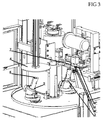
Figure 3 shows a tridimensional view of the machine according to the present invention wherein two spindles (2) and a leveling plate (4) are shown in a more detailed manner, as well as a wedge expander (5) and a knurled rotary bush (6), a sprung fork (7), and two rollers (81, 82) of the machine according to the present invention. -
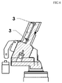
Figure 4 shows a bidimensional view of the spindle (2) wherein the position of two holding springs (3) is shown. -
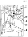
Figure 5 shows a tridimensional view of the machine according to the present invention wherein a spindle (2), a knurled rotary bush (6), a sprung fork (7), and two rollers (81, 82) tilted by 2° to 6° are shown in a more detailed manner.
Claims (8)
- A machine for pre-flanging, edging, and flanging a section of pipe (1) featuring at least one oblique end, characterized in that it comprises a spindle (2), at least one holding spring (3), a leveling plate (4), a wedge expander, a rotary bush (6), a sprung fork (7), and at least two rollers (81, 82).
- A machine according to claim 1, characterized in that the spindle (2) has a tilt from 22° to 23° or of 15° alternatively.
- A machine according to claim 1, characterized in that the rotary bush (6) is knurled.
- A machine according to claim 1, characterized in that the two rollers (81, 82) have different dimensions.
- A machine according to claim 4, characterized in that the two rollers (81, 82) have the upper or lower profile tilted by 2° to 6° alternatively.
- A machine according to claim 5, characterized in that either roller (81, 82) is made of a high performance steel (HPS) hardened to 63 HRC.
- A machine according to claim 5, characterized in that either roller (81, 82) is lapped to a roughness Ra 0.2 µm.
- A machine according to claim 5, characterized in that either roller (81, 82) is coated by modified chromium nitride CrN with a radius of 1.5 mm.
Applications Claiming Priority (1)
| Application Number | Priority Date | Filing Date | Title |
|---|---|---|---|
| ITMI20150310 | 2015-03-02 |
Publications (2)
| Publication Number | Publication Date |
|---|---|
| EP3064287A1 true EP3064287A1 (en) | 2016-09-07 |
| EP3064287B1 EP3064287B1 (en) | 2017-09-13 |
Family
ID=52815134
Family Applications (1)
| Application Number | Title | Priority Date | Filing Date |
|---|---|---|---|
| EP16000489.1A Not-in-force EP3064287B1 (en) | 2015-03-02 | 2016-03-01 | Machine for pre-flanging, edging and flanging a section of pipe with an oblique end |
Country Status (1)
| Country | Link |
|---|---|
| EP (1) | EP3064287B1 (en) |
Cited By (1)
| Publication number | Priority date | Publication date | Assignee | Title |
|---|---|---|---|---|
| CN107008791A (en) * | 2017-05-27 | 2017-08-04 | 青岛科创智能装备有限公司 | A kind of flanger |
Citations (2)
| Publication number | Priority date | Publication date | Assignee | Title |
|---|---|---|---|---|
| EP1341622B1 (en) * | 2000-12-15 | 2006-08-30 | Spiro S.A. | Folded-seam connection, method of producing it and device |
| WO2011141638A1 (en) * | 2010-05-12 | 2011-11-17 | T-Solutions Oy | Method and apparatus for making a collar to the end of a pipe |
-
2016
- 2016-03-01 EP EP16000489.1A patent/EP3064287B1/en not_active Not-in-force
Patent Citations (2)
| Publication number | Priority date | Publication date | Assignee | Title |
|---|---|---|---|---|
| EP1341622B1 (en) * | 2000-12-15 | 2006-08-30 | Spiro S.A. | Folded-seam connection, method of producing it and device |
| WO2011141638A1 (en) * | 2010-05-12 | 2011-11-17 | T-Solutions Oy | Method and apparatus for making a collar to the end of a pipe |
Cited By (1)
| Publication number | Priority date | Publication date | Assignee | Title |
|---|---|---|---|---|
| CN107008791A (en) * | 2017-05-27 | 2017-08-04 | 青岛科创智能装备有限公司 | A kind of flanger |
Also Published As
| Publication number | Publication date |
|---|---|
| EP3064287B1 (en) | 2017-09-13 |
Similar Documents
| Publication | Publication Date | Title |
|---|---|---|
| EP3067135B1 (en) | Portable pipe outer diameter-chamfering apparatus | |
| JP2015221443A (en) | Spinning device, method od manufacturing tank mirror portion, method of manufacturing tank body portion, method of manufacturing tank, and tank | |
| CN102821886B (en) | Method and apparatus for manufacturing uoe steel pipe | |
| CN103331493B (en) | A kind of technique that can improve carburizing and quenching gear internal tooth tooth Profile Machining precision | |
| EP3006128B1 (en) | Method of manufacturing a welded steel pipe | |
| US9643268B2 (en) | Device and method for partial decoating and/or machining of material from a workpiece | |
| JP2019141965A (en) | Cutting method, production method for bent article, processed plate, processing program, and creation program for processing program | |
| WO2016135005A9 (en) | Device, method, and cutting plate for machining a rotating workpiece | |
| MX2017016372A (en) | Manufacturing method for metal plate of different thickness and pressed component manufacturing method and processing machine. | |
| RU2628591C2 (en) | Device and method for edging using rollers | |
| US11607719B2 (en) | Method and apparatus for double-sided incremental flanging | |
| EP3064287B1 (en) | Machine for pre-flanging, edging and flanging a section of pipe with an oblique end | |
| JP2019209427A (en) | Processing device for edge face of steel pipe | |
| EP2018912B1 (en) | A protective tool for a bending tool | |
| KR101496228B1 (en) | Apparatus for reducing diameter of pipe and method for reducing diameter of pipe using the same | |
| Polyblank et al. | Support roller control and springback compensation in flexible spinning | |
| JP2019177395A (en) | Bending method and device of end of steel plate, manufacturing method of steel pipe, and equipment | |
| JP6407659B2 (en) | Seal strip processing method and seal strip processing apparatus | |
| EP4017675A1 (en) | Pre-weld modification technique for a custom welded blank | |
| JP6687316B2 (en) | Processing device and processing method for steel pipe end | |
| JP5831214B2 (en) | Pipe end cutting method for ERW steel pipe | |
| JP2016101610A (en) | Machining device | |
| EP3778051A1 (en) | Method and device for bending edge of steel plate, and steel pipe manufacturing method and equipment | |
| CN104439918A (en) | Rolling machining method of sealing tooth section of exhaust connecting pipe | |
| US20170252942A1 (en) | Machining device and method for producing a master-piece duplicating machine |
Legal Events
| Date | Code | Title | Description |
|---|---|---|---|
| PUAI | Public reference made under article 153(3) epc to a published international application that has entered the european phase |
Free format text: ORIGINAL CODE: 0009012 |
|
| 17P | Request for examination filed |
Effective date: 20160301 |
|
| AK | Designated contracting states |
Kind code of ref document: A1 Designated state(s): AL AT BE BG CH CY CZ DE DK EE ES FI FR GB GR HR HU IE IS IT LI LT LU LV MC MK MT NL NO PL PT RO RS SE SI SK SM TR |
|
| AX | Request for extension of the european patent |
Extension state: BA ME |
|
| GRAP | Despatch of communication of intention to grant a patent |
Free format text: ORIGINAL CODE: EPIDOSNIGR1 |
|
| STAA | Information on the status of an ep patent application or granted ep patent |
Free format text: STATUS: GRANT OF PATENT IS INTENDED |
|
| RIC1 | Information provided on ipc code assigned before grant |
Ipc: B26D 3/16 20060101ALI20170324BHEP Ipc: B21D 19/04 20060101AFI20170324BHEP Ipc: F16L 9/02 20060101ALI20170324BHEP |
|
| INTG | Intention to grant announced |
Effective date: 20170428 |
|
| GRAS | Grant fee paid |
Free format text: ORIGINAL CODE: EPIDOSNIGR3 |
|
| GRAA | (expected) grant |
Free format text: ORIGINAL CODE: 0009210 |
|
| STAA | Information on the status of an ep patent application or granted ep patent |
Free format text: STATUS: THE PATENT HAS BEEN GRANTED |
|
| AK | Designated contracting states |
Kind code of ref document: B1 Designated state(s): AL AT BE BG CH CY CZ DE DK EE ES FI FR GB GR HR HU IE IS IT LI LT LU LV MC MK MT NL NO PL PT RO RS SE SI SK SM TR |
|
| REG | Reference to a national code |
Ref country code: GB Ref legal event code: FG4D |
|
| REG | Reference to a national code |
Ref country code: CH Ref legal event code: EP |
|
| REG | Reference to a national code |
Ref country code: IE Ref legal event code: FG4D |
|
| REG | Reference to a national code |
Ref country code: AT Ref legal event code: REF Ref document number: 927625 Country of ref document: AT Kind code of ref document: T Effective date: 20171015 |
|
| REG | Reference to a national code |
Ref country code: DE Ref legal event code: R096 Ref document number: 602016000323 Country of ref document: DE |
|
| REG | Reference to a national code |
Ref country code: NL Ref legal event code: MP Effective date: 20170913 |
|
| REG | Reference to a national code |
Ref country code: LT Ref legal event code: MG4D |
|
| PG25 | Lapsed in a contracting state [announced via postgrant information from national office to epo] |
Ref country code: NO Free format text: LAPSE BECAUSE OF FAILURE TO SUBMIT A TRANSLATION OF THE DESCRIPTION OR TO PAY THE FEE WITHIN THE PRESCRIBED TIME-LIMIT Effective date: 20171213 Ref country code: LT Free format text: LAPSE BECAUSE OF FAILURE TO SUBMIT A TRANSLATION OF THE DESCRIPTION OR TO PAY THE FEE WITHIN THE PRESCRIBED TIME-LIMIT Effective date: 20170913 Ref country code: FI Free format text: LAPSE BECAUSE OF FAILURE TO SUBMIT A TRANSLATION OF THE DESCRIPTION OR TO PAY THE FEE WITHIN THE PRESCRIBED TIME-LIMIT Effective date: 20170913 Ref country code: SE Free format text: LAPSE BECAUSE OF FAILURE TO SUBMIT A TRANSLATION OF THE DESCRIPTION OR TO PAY THE FEE WITHIN THE PRESCRIBED TIME-LIMIT Effective date: 20170913 Ref country code: HR Free format text: LAPSE BECAUSE OF FAILURE TO SUBMIT A TRANSLATION OF THE DESCRIPTION OR TO PAY THE FEE WITHIN THE PRESCRIBED TIME-LIMIT Effective date: 20170913 |
|
| REG | Reference to a national code |
Ref country code: AT Ref legal event code: MK05 Ref document number: 927625 Country of ref document: AT Kind code of ref document: T Effective date: 20170913 |
|
| PG25 | Lapsed in a contracting state [announced via postgrant information from national office to epo] |
Ref country code: RS Free format text: LAPSE BECAUSE OF FAILURE TO SUBMIT A TRANSLATION OF THE DESCRIPTION OR TO PAY THE FEE WITHIN THE PRESCRIBED TIME-LIMIT Effective date: 20170913 Ref country code: BG Free format text: LAPSE BECAUSE OF FAILURE TO SUBMIT A TRANSLATION OF THE DESCRIPTION OR TO PAY THE FEE WITHIN THE PRESCRIBED TIME-LIMIT Effective date: 20171213 Ref country code: ES Free format text: LAPSE BECAUSE OF FAILURE TO SUBMIT A TRANSLATION OF THE DESCRIPTION OR TO PAY THE FEE WITHIN THE PRESCRIBED TIME-LIMIT Effective date: 20170913 Ref country code: GR Free format text: LAPSE BECAUSE OF FAILURE TO SUBMIT A TRANSLATION OF THE DESCRIPTION OR TO PAY THE FEE WITHIN THE PRESCRIBED TIME-LIMIT Effective date: 20171214 Ref country code: LV Free format text: LAPSE BECAUSE OF FAILURE TO SUBMIT A TRANSLATION OF THE DESCRIPTION OR TO PAY THE FEE WITHIN THE PRESCRIBED TIME-LIMIT Effective date: 20170913 |
|
| PG25 | Lapsed in a contracting state [announced via postgrant information from national office to epo] |
Ref country code: NL Free format text: LAPSE BECAUSE OF FAILURE TO SUBMIT A TRANSLATION OF THE DESCRIPTION OR TO PAY THE FEE WITHIN THE PRESCRIBED TIME-LIMIT Effective date: 20170913 |
|
| PG25 | Lapsed in a contracting state [announced via postgrant information from national office to epo] |
Ref country code: RO Free format text: LAPSE BECAUSE OF FAILURE TO SUBMIT A TRANSLATION OF THE DESCRIPTION OR TO PAY THE FEE WITHIN THE PRESCRIBED TIME-LIMIT Effective date: 20170913 Ref country code: CZ Free format text: LAPSE BECAUSE OF FAILURE TO SUBMIT A TRANSLATION OF THE DESCRIPTION OR TO PAY THE FEE WITHIN THE PRESCRIBED TIME-LIMIT Effective date: 20170913 Ref country code: PL Free format text: LAPSE BECAUSE OF FAILURE TO SUBMIT A TRANSLATION OF THE DESCRIPTION OR TO PAY THE FEE WITHIN THE PRESCRIBED TIME-LIMIT Effective date: 20170913 |
|
| PG25 | Lapsed in a contracting state [announced via postgrant information from national office to epo] |
Ref country code: IT Free format text: LAPSE BECAUSE OF FAILURE TO SUBMIT A TRANSLATION OF THE DESCRIPTION OR TO PAY THE FEE WITHIN THE PRESCRIBED TIME-LIMIT Effective date: 20170913 Ref country code: AT Free format text: LAPSE BECAUSE OF FAILURE TO SUBMIT A TRANSLATION OF THE DESCRIPTION OR TO PAY THE FEE WITHIN THE PRESCRIBED TIME-LIMIT Effective date: 20170913 Ref country code: IS Free format text: LAPSE BECAUSE OF FAILURE TO SUBMIT A TRANSLATION OF THE DESCRIPTION OR TO PAY THE FEE WITHIN THE PRESCRIBED TIME-LIMIT Effective date: 20180113 Ref country code: SM Free format text: LAPSE BECAUSE OF FAILURE TO SUBMIT A TRANSLATION OF THE DESCRIPTION OR TO PAY THE FEE WITHIN THE PRESCRIBED TIME-LIMIT Effective date: 20170913 Ref country code: SK Free format text: LAPSE BECAUSE OF FAILURE TO SUBMIT A TRANSLATION OF THE DESCRIPTION OR TO PAY THE FEE WITHIN THE PRESCRIBED TIME-LIMIT Effective date: 20170913 Ref country code: EE Free format text: LAPSE BECAUSE OF FAILURE TO SUBMIT A TRANSLATION OF THE DESCRIPTION OR TO PAY THE FEE WITHIN THE PRESCRIBED TIME-LIMIT Effective date: 20170913 |
|
| REG | Reference to a national code |
Ref country code: DE Ref legal event code: R026 Ref document number: 602016000323 Country of ref document: DE |
|
| PLBI | Opposition filed |
Free format text: ORIGINAL CODE: 0009260 |
|
| PLAX | Notice of opposition and request to file observation + time limit sent |
Free format text: ORIGINAL CODE: EPIDOSNOBS2 |
|
| 26 | Opposition filed |
Opponent name: NOVATEC ENGINEERING S.R.L. Effective date: 20180613 |
|
| PG25 | Lapsed in a contracting state [announced via postgrant information from national office to epo] |
Ref country code: DK Free format text: LAPSE BECAUSE OF FAILURE TO SUBMIT A TRANSLATION OF THE DESCRIPTION OR TO PAY THE FEE WITHIN THE PRESCRIBED TIME-LIMIT Effective date: 20170913 |
|
| REG | Reference to a national code |
Ref country code: DE Ref legal event code: R119 Ref document number: 602016000323 Country of ref document: DE |
|
| PG25 | Lapsed in a contracting state [announced via postgrant information from national office to epo] |
Ref country code: MC Free format text: LAPSE BECAUSE OF FAILURE TO SUBMIT A TRANSLATION OF THE DESCRIPTION OR TO PAY THE FEE WITHIN THE PRESCRIBED TIME-LIMIT Effective date: 20170913 Ref country code: SI Free format text: LAPSE BECAUSE OF FAILURE TO SUBMIT A TRANSLATION OF THE DESCRIPTION OR TO PAY THE FEE WITHIN THE PRESCRIBED TIME-LIMIT Effective date: 20170913 |
|
| PLBB | Reply of patent proprietor to notice(s) of opposition received |
Free format text: ORIGINAL CODE: EPIDOSNOBS3 |
|
| REG | Reference to a national code |
Ref country code: BE Ref legal event code: MM Effective date: 20180331 |
|
| REG | Reference to a national code |
Ref country code: IE Ref legal event code: MM4A |
|
| PG25 | Lapsed in a contracting state [announced via postgrant information from national office to epo] |
Ref country code: LU Free format text: LAPSE BECAUSE OF NON-PAYMENT OF DUE FEES Effective date: 20180301 |
|
| PG25 | Lapsed in a contracting state [announced via postgrant information from national office to epo] |
Ref country code: IE Free format text: LAPSE BECAUSE OF NON-PAYMENT OF DUE FEES Effective date: 20180301 Ref country code: DE Free format text: LAPSE BECAUSE OF NON-PAYMENT OF DUE FEES Effective date: 20181002 |
|
| PG25 | Lapsed in a contracting state [announced via postgrant information from national office to epo] |
Ref country code: BE Free format text: LAPSE BECAUSE OF NON-PAYMENT OF DUE FEES Effective date: 20180331 |
|
| PG25 | Lapsed in a contracting state [announced via postgrant information from national office to epo] |
Ref country code: FR Free format text: LAPSE BECAUSE OF NON-PAYMENT OF DUE FEES Effective date: 20180331 |
|
| REG | Reference to a national code |
Ref country code: CH Ref legal event code: PL |
|
| PG25 | Lapsed in a contracting state [announced via postgrant information from national office to epo] |
Ref country code: CH Free format text: LAPSE BECAUSE OF NON-PAYMENT OF DUE FEES Effective date: 20190331 Ref country code: LI Free format text: LAPSE BECAUSE OF NON-PAYMENT OF DUE FEES Effective date: 20190331 Ref country code: MT Free format text: LAPSE BECAUSE OF NON-PAYMENT OF DUE FEES Effective date: 20180301 |
|
| REG | Reference to a national code |
Ref country code: DE Ref legal event code: R100 Ref document number: 602016000323 Country of ref document: DE |
|
| PLCK | Communication despatched that opposition was rejected |
Free format text: ORIGINAL CODE: EPIDOSNREJ1 |
|
| PG25 | Lapsed in a contracting state [announced via postgrant information from national office to epo] |
Ref country code: TR Free format text: LAPSE BECAUSE OF FAILURE TO SUBMIT A TRANSLATION OF THE DESCRIPTION OR TO PAY THE FEE WITHIN THE PRESCRIBED TIME-LIMIT Effective date: 20170913 |
|
| PG25 | Lapsed in a contracting state [announced via postgrant information from national office to epo] |
Ref country code: PT Free format text: LAPSE BECAUSE OF FAILURE TO SUBMIT A TRANSLATION OF THE DESCRIPTION OR TO PAY THE FEE WITHIN THE PRESCRIBED TIME-LIMIT Effective date: 20170913 |
|
| PG25 | Lapsed in a contracting state [announced via postgrant information from national office to epo] |
Ref country code: MK Free format text: LAPSE BECAUSE OF NON-PAYMENT OF DUE FEES Effective date: 20170913 Ref country code: CY Free format text: LAPSE BECAUSE OF FAILURE TO SUBMIT A TRANSLATION OF THE DESCRIPTION OR TO PAY THE FEE WITHIN THE PRESCRIBED TIME-LIMIT Effective date: 20170913 Ref country code: HU Free format text: LAPSE BECAUSE OF FAILURE TO SUBMIT A TRANSLATION OF THE DESCRIPTION OR TO PAY THE FEE WITHIN THE PRESCRIBED TIME-LIMIT; INVALID AB INITIO Effective date: 20160301 |
|
| PLBN | Opposition rejected |
Free format text: ORIGINAL CODE: 0009273 |
|
| STAA | Information on the status of an ep patent application or granted ep patent |
Free format text: STATUS: OPPOSITION REJECTED |
|
| PG25 | Lapsed in a contracting state [announced via postgrant information from national office to epo] |
Ref country code: AL Free format text: LAPSE BECAUSE OF FAILURE TO SUBMIT A TRANSLATION OF THE DESCRIPTION OR TO PAY THE FEE WITHIN THE PRESCRIBED TIME-LIMIT Effective date: 20170913 |
|
| 27O | Opposition rejected |
Effective date: 20200203 |
|
| GBPC | Gb: european patent ceased through non-payment of renewal fee |
Effective date: 20200301 |
|
| PG25 | Lapsed in a contracting state [announced via postgrant information from national office to epo] |
Ref country code: GB Free format text: LAPSE BECAUSE OF NON-PAYMENT OF DUE FEES Effective date: 20200301 |