EP3063830B1 - Broad band radome for microwave antenna - Google Patents
Broad band radome for microwave antenna Download PDFInfo
- Publication number
- EP3063830B1 EP3063830B1 EP14857532.7A EP14857532A EP3063830B1 EP 3063830 B1 EP3063830 B1 EP 3063830B1 EP 14857532 A EP14857532 A EP 14857532A EP 3063830 B1 EP3063830 B1 EP 3063830B1
- Authority
- EP
- European Patent Office
- Prior art keywords
- radome
- structural layer
- antenna
- layer
- outer layer
- Prior art date
- Legal status (The legal status is an assumption and is not a legal conclusion. Google has not performed a legal analysis and makes no representation as to the accuracy of the status listed.)
- Not-in-force
Links
Images









Classifications
-
- H—ELECTRICITY
- H01—ELECTRIC ELEMENTS
- H01Q—ANTENNAS, i.e. RADIO AERIALS
- H01Q1/00—Details of, or arrangements associated with, antennas
- H01Q1/42—Housings not intimately mechanically associated with radiating elements, e.g. radome
-
- B—PERFORMING OPERATIONS; TRANSPORTING
- B29—WORKING OF PLASTICS; WORKING OF SUBSTANCES IN A PLASTIC STATE IN GENERAL
- B29C—SHAPING OR JOINING OF PLASTICS; SHAPING OF MATERIAL IN A PLASTIC STATE, NOT OTHERWISE PROVIDED FOR; AFTER-TREATMENT OF THE SHAPED PRODUCTS, e.g. REPAIRING
- B29C44/00—Shaping by internal pressure generated in the material, e.g. swelling or foaming ; Producing porous or cellular expanded plastics articles
- B29C44/02—Shaping by internal pressure generated in the material, e.g. swelling or foaming ; Producing porous or cellular expanded plastics articles for articles of definite length, i.e. discrete articles
- B29C44/12—Incorporating or moulding on preformed parts, e.g. inserts or reinforcements
- B29C44/1271—Incorporating or moulding on preformed parts, e.g. inserts or reinforcements the preformed parts being partially covered
-
- H—ELECTRICITY
- H01—ELECTRIC ELEMENTS
- H01Q—ANTENNAS, i.e. RADIO AERIALS
- H01Q1/00—Details of, or arrangements associated with, antennas
- H01Q1/42—Housings not intimately mechanically associated with radiating elements, e.g. radome
- H01Q1/422—Housings not intimately mechanically associated with radiating elements, e.g. radome comprising two or more layers of dielectric material
- H01Q1/424—Housings not intimately mechanically associated with radiating elements, e.g. radome comprising two or more layers of dielectric material comprising a layer of expanded material
-
- H—ELECTRICITY
- H01—ELECTRIC ELEMENTS
- H01Q—ANTENNAS, i.e. RADIO AERIALS
- H01Q15/00—Devices for reflection, refraction, diffraction or polarisation of waves radiated from an antenna, e.g. quasi-optical devices
- H01Q15/14—Reflecting surfaces; Equivalent structures
- H01Q15/16—Reflecting surfaces; Equivalent structures curved in two dimensions [2D], e.g. paraboloidal
-
- B—PERFORMING OPERATIONS; TRANSPORTING
- B29—WORKING OF PLASTICS; WORKING OF SUBSTANCES IN A PLASTIC STATE IN GENERAL
- B29K—INDEXING SCHEME ASSOCIATED WITH SUBCLASSES B29B, B29C OR B29D, RELATING TO MOULDING MATERIALS OR TO MATERIALS FOR MOULDS, REINFORCEMENTS, FILLERS OR PREFORMED PARTS, e.g. INSERTS
- B29K2101/00—Use of unspecified macromolecular compounds as moulding material
- B29K2101/12—Thermoplastic materials
-
- B—PERFORMING OPERATIONS; TRANSPORTING
- B29—WORKING OF PLASTICS; WORKING OF SUBSTANCES IN A PLASTIC STATE IN GENERAL
- B29K—INDEXING SCHEME ASSOCIATED WITH SUBCLASSES B29B, B29C OR B29D, RELATING TO MOULDING MATERIALS OR TO MATERIALS FOR MOULDS, REINFORCEMENTS, FILLERS OR PREFORMED PARTS, e.g. INSERTS
- B29K2105/00—Condition, form or state of moulded material or of the material to be shaped
- B29K2105/04—Condition, form or state of moulded material or of the material to be shaped cellular or porous
-
- B—PERFORMING OPERATIONS; TRANSPORTING
- B29—WORKING OF PLASTICS; WORKING OF SUBSTANCES IN A PLASTIC STATE IN GENERAL
- B29L—INDEXING SCHEME ASSOCIATED WITH SUBCLASS B29C, RELATING TO PARTICULAR ARTICLES
- B29L2031/00—Other particular articles
- B29L2031/34—Electrical apparatus, e.g. sparking plugs or parts thereof
- B29L2031/3456—Antennas, e.g. radomes
Definitions
- This invention relates to microwave reflector antennas. More particularly, the invention relates to a cost-efficient broad band radome for a microwave reflector antenna.
- the open end of a reflector antenna is typically enclosed by a radome coupled to the distal end (the open end) of the reflector dish.
- the radome provides environmental protection and improves wind load characteristics of the antenna. Because reflector antennas are often mounted in remote locations, such as high atop radio towers, a radome failure may incur significant repair/replacement expense.
- a radome may be tuned to optimize the electrical performance of a reflector antenna, for example by dimensioning the radome surfaces to re-direct RF reflections in a desired direction.
- the radome materials and/or their thickness may be applied to self-cancel reflections.
- these tuned radomes then become antenna and/or operating frequency specific, requiring design, manufacture and inventory of a large collection of different radomes.
- Radomes utilizing a foamed polymer material mated with at least one layer of woven (anisotropic) material providing additional strength are known, for example as missile or aircraft radomes.
- the resulting composite may be significantly stronger and/or more expensive to manufacture than required for a static earth station reflector antenna.
- Patent Document GB 2 225 902 A relates to a dish antenna comprising a reflector, a horn and a rigid, shaped convex cover, the cover enclosing the horn and being sealed to the periphery of the reflector.
- Patent Document US 2010/315307 A1 relates to an enclosure for the open end of a reflector antenna which includes a cylindrical shroud coupled to a distal end of the reflector antenna, the shroud generally coaxial with a longitudinal axis of the reflector antenna.
- a retaining band is coupled to an inner diameter of the shroud, proximate a distal end of the shroud.
- the retaining band is provided with a retaining groove open radially inward towards the longitudinal axis.
- the retaining groove provided with a bottom extending radially outward beyond an outer diameter of the shroud.
- a radome is seated within the retaining groove.
- Patent Document US 2005/190116 A1 relates to a radome adapted to reduce backlobes of an associated reflector antenna via application of a conductive ring with an inward facing edge about the periphery of the radome.
- Patent Document US 2013/002515 A1 relates to a band clamp for coupling a radome to a distal end of a reflector dish for improving the front to back ratio of a reflector antenna, provided with an inward projecting proximal lip and an inward projecting distal lip.
- the distal lip is dimensioned with an inner diameter equal to or less than a reflector aperture of the reflector dish.
- the proximal lip may be provided with an inward bias dimensioned to engage the reflector dish in an interference fit and/or turnback region dimensioned to engage an outer surface of a signal area of the reflector dish in an interference fit.
- a variety of different configurations of protruding portions extending from the band clamp may be applied to further improve electrical performance.
- the inventors have recognized that a composite of a moisture resistant isotropic film outer layer and a structural layer of low density foamed polymer material can result in a radome with adequate strength which is essentially RF transparent, enabling a single radome to be utilized with a broad range of microwave frequency bands.
- a radome 1 has an isotropic outer layer 3 coupled to a structural layer 5 of foam material that is retained on a reflector dish 7, enclosing an open end of the reflector antenna 9.
- An isotropic material as applied herein is one in which the material has a substantially homogeneous distribution. That is, the material is not a woven or fiber infused material, but a substantially uniformly distributed homogeneous material, such as a polymer film, coating or the like.
- the outer layer 3 may be, for example, a polymer and/or blend of polymers, such as, polycarbonate, Acrylonitrile Styrene Acrylate, Polyvinyl chloride, Polymethyl methacrylate, Thermoplastic polyolefin, Ethylene-Vinyl Acetate, Acrylonitrile Butadiene Styrene or the like.
- the outer layer 3 may be a film applied upon the structural layer 5 or a coating sprayed or painted upon the structural layer 5.
- the outer layer 3 may provide ultra-violet and/or impact protection for the structural layer 5 as well as a moisture barrier to inhibit moisture from being absorbed into the foam material of the structural layer 5 which could otherwise degrade the structural integrity and/or electrical performance of the radome 1. Any outer layer 3 with suitable moisture and ultra-violet radiation resistance characteristics may be applied.
- the outer layer 3 may include signage and/or graphics for aesthetics and/or marketing purposes. In a balance between moisture resistance and material cost, the outer layer 3 may be provided with a thickness of 0.5 millimeters or less.
- US Utility Patent No. 4896164 "Radar Transparent Window for Commercial Buildings", issued to Burke et al, January 23, 1990, describes a conventional tuned sandwich radome structure ( Figure 2 of US 4896164 ) with interior and exterior layers of polyester resin/E-glass (fiberglass) laminate provided on front and back sides of a rigid polyimide foam with a specific thickness selected with respect to conventional reflection cancellation.
- an exemplary embodiment of a 0.1mm thick outer layer 3 (2.8 dielectric constant) and 25 mm structural layer 5 (1.11 dielectric constant), with an uncovered signal transmission surface 11 of the inner side 13 has a significantly improved broadband characteristic with respect to insertion and return loss, as demonstrated in Figures 5 and 6 , respectively.
- the insertion loss of the exemplary embodiment composite radome is minimal over the 36 GHz range between 6 and 42 GHz, the prior tuned structure is effectively unusable outside of two narrow 4 GHz wide bands of 8-12 and 27-31 GHz.
- the outer layer 3 may extend proximate to an outer diameter 15 of the structural layer 5 ( Figure 4 ), to the outer diameter 15 of the structural layer 5 ( Figure 7 ) and/or around the outer diameter 15 to the inner side 13 of the structural layer 5, without extending radially inward to the signal transmission surface 11 of the inner side 13 ( Figure 8 ).
- the reflector dish 7 With the radome 1 seated upon the open end of the reflector dish 7, the reflector dish 7 provides the remainder of the moisture seal with respect to the cavity enclosed by the radome 1, so the inner side 13 of the structural layer 5, or just the signal transmission surface 11 of the inner side 13, may be uncovered.
- the structural layer 5 may be provided as a foamed polymer such as polystyrene, polyurethane, polyethylene, polypropylene or the like.
- the structural layer 5 may be provided with a thickness selected with respect to structural properties of the selected material and/or the necessary diameter of the radome to provide a structural strength to the resulting radome 1 which corresponds to a strength and/or rigidity required for the range of environmental conditions expected at the desired reflector antenna 9 installation(s).
- the structural layer 5 may be provided with a thickness from a distal end of the reflector dish 7 of at least 2 wavelengths of a minimum operating frequency, such that a conductive retaining element 23 or conductive edge 41 applied at the radome periphery is also operative as a shield portion inhibiting generation of backlobes in the signal pattern of the resulting antenna 9.
- the foamed polymer of the structural layer 5 may be cut to size or cost efficiently molded with a high level of precision, in any desired profile.
- the radome 1 may be provided with a profile configured to extend inwardly or outwardly to further reduce return loss, enhance wind loading, and/or improve the strength characteristics of the radome.
- a domed profile may be applied wherein the center of the radome arcs outwardly or inwardly from the periphery of the radome, for example as shown in Figures 9-12 .
- the inner side 13 of the radome 1 may be provided flat ( Figure 10 ) or with a corresponding outward or inward arc ( Figures 9 , 11 and 12 ).
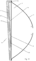
- the inward or outward extension of the radome 1 may be conical, for example as shown in Figure 13 , and/or the radome 1 may be provided with an angled face plane, for example as shown in Figure 14 , to improve both ice shedding and return loss characteristics of the reflector antenna 9.
- the inner side 13 of the structural layer 5 may be provided with one or more inward projections 19, dimensioned to extend inwardly from the distal end of the reflector dish 7, seating also along the inner signal surface 17 of the reflector dish 7, for example as shown in Figures 15 and 16 .
- the inward projections 19 of the structural layer 5 may be applied as reinforcing rings and/or ribs, for example as shown in Figure 16 , which extend inwardly of a plane of a retaining flange 29 of the reflector dish 9 of the antenna.
- the radome 1 may be coupled to the reflector dish 7 via fasteners 21 such as screws or the like which retain the radome directly upon the distal end of the reflector dish 7 and/or which secure a retaining element 23, such as a metal band, which may protect the periphery of the radome 1 and/or further secure the radome 1 in place.
- the fasteners 21 may extend through the retaining element 23 and into the structural layer 5 ( Figures 4 , 17 ) or fully through the structural layer 5 and two edges of the retaining element 23 ( Figure 18 ).
- the retaining element 23 may be applied with an outer edge 25 seated against an outer surface 27 of the retaining flange 29 of the reflector dish 7, for example as shown in Figure 4 .
- the retaining element 23 may seat against an inner seat surface 31 of the retaining flange 29 ( Figure 19 ), providing an overlapping mechanical interlock between the elements and extending the path required for signal leakage to occur therebetween.
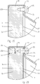
- the retaining flange 29 may be formed with a periphery portion 33 coaxial with a longitudinal axis of the reflector antenna 9, enabling the retaining element 23 to be provided with an "L” rather than "C” cross-section, the retaining element 23 retained by fasteners 21 extending radially inwardly through the periphery portion 33 into the retaining element 23 and further into the radome 1, as shown for example in Figure 17 .
- the retaining element 23 may also be utilized to retain an RF absorber 35 seated in a periphery shoulder 37 of the radome 1, for example as shown in Figure 20 .
- the retaining element 23 is further provided in a generally S-shaped cross-section, dimensioned to provide both an inward and an outward facing choke groove 39 for inhibiting back lobes in the resulting reflector antenna signal pattern, for example as shown in Figure 21 .
- this configuration also enables a fastener 21 (provided, for example, as a bolt and nut) to avoid penetrating the structural layer or a signal area of the radome 1, which may avoid secondary sealing issues created by multiple fasteners 21 penetrating through the retaining element 23 into the signal area of the radome 1 itself.
- a fastener 21 provided, for example, as a bolt and nut
- the radome 1 may also be retained on the distal end of the reflector dish, without an additional retaining element 23. Where the retaining element 23 is omitted, a conductive edge 41, formed for example via metalizing, electrodaging, overmolding, metallic paint, foil or the like, may be applied to assist with signal pattern backlobe cancellation either on top of or under the outer layer 3, for example as shown in Figures 22 and 23 .
- the bonding of the outer layer 3 to the structural layer 5 may be secured, for example by application of an adhesive therebetween and/or integrally with a molding/foaming process of the structural layer 5.
- an initial molding of the structural layer 5 may be performed and the mold opened for insertion of the outer layer 3.
- the outer layer 3 may be applied via spraying, either upon the mold or upon the structural layer 5. With the outer layer 3 in place, the mold may be closed again and final molding/foaming completed with an additional time period.
- the outer layer 3 may be inserted or sprayed into an empty mold and the structural layer 5 molded upon it. Thereby, the composite of the structural layer 5 and outer layer 3 may be formed without use of an additional adhesive.
- the mold may include vacuum-forming functionality to draw the outer layer 3 into the desired extent, either in a separate operation or via vacuum forming the thin film of the outer layer 3 in situ within the mold before the structural layer 5 is foamed on top of it.
- the outer layer 3 may be heat shrunk upon the structural layer 5.
- the ability to provide a single cost efficient radome 1, usable on a wide range of operating frequency bands, may enable significant reflector antenna manufacturing cost efficiencies.
- the self supporting characteristic of the structural layer enables simplified radome to reflector antenna attachment arrangements with electrical performance enhancing characteristics that may also be cost effective and/or easily adaptable to a wide range of different reflector dishes 7.
Landscapes
- Physics & Mathematics (AREA)
- Electromagnetism (AREA)
- Details Of Aerials (AREA)
- Aerials With Secondary Devices (AREA)
Description
- This invention relates to microwave reflector antennas. More particularly, the invention relates to a cost-efficient broad band radome for a microwave reflector antenna.
- The open end of a reflector antenna is typically enclosed by a radome coupled to the distal end (the open end) of the reflector dish. The radome provides environmental protection and improves wind load characteristics of the antenna. Because reflector antennas are often mounted in remote locations, such as high atop radio towers, a radome failure may incur significant repair/replacement expense.
- A radome may be tuned to optimize the electrical performance of a reflector antenna, for example by dimensioning the radome surfaces to re-direct RF reflections in a desired direction. The radome materials and/or their thickness may be applied to self-cancel reflections. However, these tuned radomes then become antenna and/or operating frequency specific, requiring design, manufacture and inventory of a large collection of different radomes.
- Radomes utilizing a foamed polymer material mated with at least one layer of woven (anisotropic) material providing additional strength are known, for example as missile or aircraft radomes. However, the resulting composite may be significantly stronger and/or more expensive to manufacture than required for a static earth station reflector antenna.
- Competition in the reflector antenna market has focused attention on improving electrical performance and minimization of overall manufacturing, inventory, distribution, installation and/or maintenance costs. Therefore, it is an object of the invention to provide a radome that overcomes deficiencies in the prior art.
-
Patent Document GB 2 225 902 A - Patent Document
US 2010/315307 A1 relates to an enclosure for the open end of a reflector antenna which includes a cylindrical shroud coupled to a distal end of the reflector antenna, the shroud generally coaxial with a longitudinal axis of the reflector antenna. A retaining band is coupled to an inner diameter of the shroud, proximate a distal end of the shroud. The retaining band is provided with a retaining groove open radially inward towards the longitudinal axis. The retaining groove provided with a bottom extending radially outward beyond an outer diameter of the shroud. A radome is seated within the retaining groove. - Patent Document
US 2005/190116 A1 relates to a radome adapted to reduce backlobes of an associated reflector antenna via application of a conductive ring with an inward facing edge about the periphery of the radome. - Patent Document
US 2013/002515 A1 relates to a band clamp for coupling a radome to a distal end of a reflector dish for improving the front to back ratio of a reflector antenna, provided with an inward projecting proximal lip and an inward projecting distal lip. The distal lip is dimensioned with an inner diameter equal to or less than a reflector aperture of the reflector dish. The proximal lip may be provided with an inward bias dimensioned to engage the reflector dish in an interference fit and/or turnback region dimensioned to engage an outer surface of a signal area of the reflector dish in an interference fit. A variety of different configurations of protruding portions extending from the band clamp may be applied to further improve electrical performance. - The accompanying drawings, which are incorporated in and constitute a part of this specification, illustrate an embodiment of the invention and examples useful for understanding the invention, where like reference numbers in the drawing figures refer to the same feature or element and may not be described in detail for every drawing figure in which they appear and, together with a general description of the invention given above, and the detailed description of the embodiment and examples given below, serve to explain the principles of the invention.
-
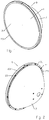
Figure 1 is a schematic isometric angled front view of an exemplary radome mounted on the reflector dish of a reflector antenna. -
Figure 2 is a schematic isometric angled back view of the reflector antenna ofFigure 1 , antenna hub and mounting assembly removed for clarity. -
Figure 3 is a schematic cut-away side view of the reflector antenna ofFigure 1 , with the feed assembly, antenna hub and mounting assembly removed for clarity. -
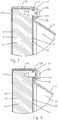
Figure 4 is a close-up view of area C ofFigure 3 . -
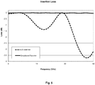
Figure 5 is a calculated insertion loss chart comparing an exemplary radome to a prior art radome. -
Figure 6 is a calculated return loss chart comparing an exemplary radome to a prior art radome. -
Figure 7 is a schematic close-up view of an alternative example useful for understanding the present invention of a radome coupled to a reflector dish, demonstrating the outer layer extending over the outer diameter of the structural layer. -
Figure 8 is a schematic close-up view of an alternative example useful for understanding the present invention of a radome coupled to a reflector dish, demonstrating the outer layer extending around the outer diameter to the inner side of the structural layer. -
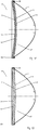
Figure 9 is a schematic cut-away side view of an alternative example useful for understanding the present invention of a radome coupled to a reflector antenna, demonstrating a domed antenna profile. The feed assembly, antenna hub and mounting assembly have been removed for clarity. -
Figure 10 is a schematic cut-away side view of an alternative example useful for understanding the present invention of a radome coupled to a reflector antenna, demonstrating a domed radome profile. The feed assembly, antenna hub and mounting assembly have been removed for clarity. -
Figure 11 is a schematic cut-away side view of an alternative example useful for understanding the present invention of a radome coupled to a reflector antenna, demonstrating a domed radome profile. The feed assembly, antenna hub and mounting assembly have been removed for clarity. -
Figure 12 is a schematic cut-away side view of an alternative example useful for understanding the present invention of a radome coupled to a reflector antenna, demonstrating an inwardly domed radome profile. The feed assembly, antenna hub and mounting assembly have been removed for clarity. -
Figure 13 is a schematic cut-away side view of an alternative example useful for understanding the present invention of a radome coupled to a reflector antenna, demonstrating an inwardly conical radome profile. The feed assembly, antenna hub and mounting assembly have been removed for clarity. -
Figure 14 is a schematic cut-away side view of an alternative example useful for understanding the present invention of a radome coupled to a reflector antenna, demonstrating an angled planar face radome profile. The feed assembly, antenna hub and mounting assembly have been removed for clarity. -
Figure 15 is a schematic cut-away side view of an alternative example useful for understanding the present invention of a radome coupled to a reflector antenna, demonstrating a structural layer projecting inwardly to the signal space of the reflector dish. The feed assembly, antenna hub and mounting assembly have been removed for clarity. -
Figure 16 is a schematic cut-away side view of an alternative example useful for understanding the present invention of a radome coupled to a reflector antenna, demonstrating a structural layer projecting inwardly to the signal space of the reflector dish. The feed assembly, antenna hub and mounting assembly have been removed for clarity. -
Figure 17 is a schematic close-up view of an alternative example useful for understanding the present invention of a radome coupled to a reflector dish, demonstrating a retaining flange with a periphery portion. -
Figure 18 is a schematic close-up view of an alternative example useful for understanding the present invention of a radome coupled to a reflector dish, demonstrating through fastening between the retaining flange and the retaining element. -
Figure 19 is a schematic close-up view of an alternative example useful for understanding the present invention of a radome coupled to a reflector dish, demonstrating overlapping of the retaining flange and the retaining element. -
Figure 20 is a schematic close-up view of an alternative example useful for understanding the present invention of a radome coupled to a reflector dish, demonstrating an RF absorber seated in a periphery shoulder of the structural layer. -
Figure 21 is a schematic close-up view of an embodiment according to the claimed invention of a radome coupled to a reflector dish, demonstrating a retaining element with an S-shaped cross- section with inner and outer choke grooves. -
Figure 22 is a schematic close-up view of an alternative example useful for understanding the present invention of a radome coupled to a reflector dish, demonstrating a radome coupled without a retaining element, with a conductive groove and the outer layer represented separate from the structural layer for clarity. -
Figure 23 is a schematic close-up view of an alternative example useful for understanding the present invention of a radome coupled to a reflector dish, demonstrating a radome coupled without a retaining element, with a conductive groove and the outer layer represented separate from the structural layer for clarity. - According to the invention, the problem is solved by the subject-matter outlined in the independent claims. Advantageous further developments of the invention are set forth in the dependent claims.
- The inventors have recognized that a composite of a moisture resistant isotropic film outer layer and a structural layer of low density foamed polymer material can result in a radome with adequate strength which is essentially RF transparent, enabling a single radome to be utilized with a broad range of microwave frequency bands.
- As shown for example in
Figures 1 -4 , aradome 1 has an isotropicouter layer 3 coupled to astructural layer 5 of foam material that is retained on areflector dish 7, enclosing an open end of thereflector antenna 9. An isotropic material as applied herein is one in which the material has a substantially homogeneous distribution. That is, the material is not a woven or fiber infused material, but a substantially uniformly distributed homogeneous material, such as a polymer film, coating or the like. Theouter layer 3 may be, for example, a polymer and/or blend of polymers, such as, polycarbonate, Acrylonitrile Styrene Acrylate, Polyvinyl chloride, Polymethyl methacrylate, Thermoplastic polyolefin, Ethylene-Vinyl Acetate, Acrylonitrile Butadiene Styrene or the like. - The
outer layer 3 may be a film applied upon thestructural layer 5 or a coating sprayed or painted upon thestructural layer 5. Theouter layer 3 may provide ultra-violet and/or impact protection for thestructural layer 5 as well as a moisture barrier to inhibit moisture from being absorbed into the foam material of thestructural layer 5 which could otherwise degrade the structural integrity and/or electrical performance of theradome 1. Anyouter layer 3 with suitable moisture and ultra-violet radiation resistance characteristics may be applied. Further, theouter layer 3 may include signage and/or graphics for aesthetics and/or marketing purposes. In a balance between moisture resistance and material cost, theouter layer 3 may be provided with a thickness of 0.5 millimeters or less. -
US Utility Patent No. 4896164 , "Radar Transparent Window for Commercial Buildings", issued to Burke et al, January 23, 1990, describes a conventional tuned sandwich radome structure (Figure 2 ofUS 4896164 ) with interior and exterior layers of polyester resin/E-glass (fiberglass) laminate provided on front and back sides of a rigid polyimide foam with a specific thickness selected with respect to conventional reflection cancellation. In contrast, an exemplary embodiment of a 0.1mm thick outer layer 3 (2.8 dielectric constant) and 25 mm structural layer 5 (1.11 dielectric constant), with an uncoveredsignal transmission surface 11 of theinner side 13 has a significantly improved broadband characteristic with respect to insertion and return loss, as demonstrated inFigures 5 and6 , respectively. Notably, while the insertion loss of the exemplary embodiment composite radome is minimal over the 36 GHz range between 6 and 42 GHz, the prior tuned structure is effectively unusable outside of two narrow 4 GHz wide bands of 8-12 and 27-31 GHz. - As best shown for example in
Figures 4 and7-8 , theouter layer 3 may extend proximate to anouter diameter 15 of the structural layer 5 (Figure 4 ), to theouter diameter 15 of the structural layer 5 (Figure 7 ) and/or around theouter diameter 15 to theinner side 13 of thestructural layer 5, without extending radially inward to thesignal transmission surface 11 of the inner side 13 (Figure 8 ). With theradome 1 seated upon the open end of thereflector dish 7, thereflector dish 7 provides the remainder of the moisture seal with respect to the cavity enclosed by theradome 1, so theinner side 13 of thestructural layer 5, or just thesignal transmission surface 11 of theinner side 13, may be uncovered. - The
structural layer 5 may be provided as a foamed polymer such as polystyrene, polyurethane, polyethylene, polypropylene or the like. Thestructural layer 5 may be provided with a thickness selected with respect to structural properties of the selected material and/or the necessary diameter of the radome to provide a structural strength to the resultingradome 1 which corresponds to a strength and/or rigidity required for the range of environmental conditions expected at the desiredreflector antenna 9 installation(s). - The
structural layer 5 may be provided with a thickness from a distal end of thereflector dish 7 of at least 2 wavelengths of a minimum operating frequency, such that aconductive retaining element 23 orconductive edge 41 applied at the radome periphery is also operative as a shield portion inhibiting generation of backlobes in the signal pattern of the resultingantenna 9. - The foamed polymer of the
structural layer 5 may be cut to size or cost efficiently molded with a high level of precision, in any desired profile. For example, theradome 1 may be provided with a profile configured to extend inwardly or outwardly to further reduce return loss, enhance wind loading, and/or improve the strength characteristics of the radome. A domed profile may be applied wherein the center of the radome arcs outwardly or inwardly from the periphery of the radome, for example as shown inFigures 9-12 . Theinner side 13 of theradome 1 may be provided flat (Figure 10 ) or with a corresponding outward or inward arc (Figures 9 ,11 and12 ). Alternatively, the inward or outward extension of theradome 1 may be conical, for example as shown inFigure 13 , and/or theradome 1 may be provided with an angled face plane, for example as shown inFigure 14 , to improve both ice shedding and return loss characteristics of thereflector antenna 9. - To enable an increased thickness of the
structural layer 5, for example for enhanced strength characteristics, without extending the outer dimensions of thereflector antenna 9, theinner side 13 of thestructural layer 5 may be provided with one or more inward projections 19, dimensioned to extend inwardly from the distal end of thereflector dish 7, seating also along theinner signal surface 17 of thereflector dish 7, for example as shown inFigures 15 and 16 . To minimize material requirements of the thickenedstructural layer 5, the inward projections 19 of thestructural layer 5 may be applied as reinforcing rings and/or ribs, for example as shown inFigure 16 , which extend inwardly of a plane of a retainingflange 29 of thereflector dish 9 of the antenna. - As shown for example in
Figure 4 , theradome 1 may be coupled to thereflector dish 7 viafasteners 21 such as screws or the like which retain the radome directly upon the distal end of thereflector dish 7 and/or which secure a retainingelement 23, such as a metal band, which may protect the periphery of theradome 1 and/or further secure theradome 1 in place. Thefasteners 21 may extend through the retainingelement 23 and into the structural layer 5 (Figures 4 ,17 ) or fully through thestructural layer 5 and two edges of the retaining element 23 (Figure 18 ). - The retaining
element 23 may be applied with anouter edge 25 seated against anouter surface 27 of the retainingflange 29 of thereflector dish 7, for example as shown inFigure 4 . Alternatively, the retainingelement 23 may seat against aninner seat surface 31 of the retaining flange 29 (Figure 19 ), providing an overlapping mechanical interlock between the elements and extending the path required for signal leakage to occur therebetween. The retainingflange 29 may be formed with aperiphery portion 33 coaxial with a longitudinal axis of thereflector antenna 9, enabling the retainingelement 23 to be provided with an "L" rather than "C" cross-section, the retainingelement 23 retained byfasteners 21 extending radially inwardly through theperiphery portion 33 into the retainingelement 23 and further into theradome 1, as shown for example inFigure 17 . - The retaining
element 23 may also be utilized to retain anRF absorber 35 seated in aperiphery shoulder 37 of theradome 1, for example as shown inFigure 20 . According to the invention, the retainingelement 23 is further provided in a generally S-shaped cross-section, dimensioned to provide both an inward and an outward facing choke groove 39 for inhibiting back lobes in the resulting reflector antenna signal pattern, for example as shown inFigure 21 . In addition to electrical performance benefits, this configuration also enables a fastener 21 (provided, for example, as a bolt and nut) to avoid penetrating the structural layer or a signal area of theradome 1, which may avoid secondary sealing issues created bymultiple fasteners 21 penetrating through the retainingelement 23 into the signal area of theradome 1 itself. - The
radome 1 may also be retained on the distal end of the reflector dish, without anadditional retaining element 23. Where the retainingelement 23 is omitted, aconductive edge 41, formed for example via metalizing, electrodaging, overmolding, metallic paint, foil or the like, may be applied to assist with signal pattern backlobe cancellation either on top of or under theouter layer 3, for example as shown inFigures 22 and 23 . - The bonding of the
outer layer 3 to thestructural layer 5 may be secured, for example by application of an adhesive therebetween and/or integrally with a molding/foaming process of thestructural layer 5. For example, an initial molding of thestructural layer 5 may be performed and the mold opened for insertion of theouter layer 3. Alternatively, theouter layer 3 may be applied via spraying, either upon the mold or upon thestructural layer 5. With theouter layer 3 in place, the mold may be closed again and final molding/foaming completed with an additional time period. Alternatively, theouter layer 3 may be inserted or sprayed into an empty mold and thestructural layer 5 molded upon it. Thereby, the composite of thestructural layer 5 andouter layer 3 may be formed without use of an additional adhesive. Similarly, the mold may include vacuum-forming functionality to draw theouter layer 3 into the desired extent, either in a separate operation or via vacuum forming the thin film of theouter layer 3 in situ within the mold before thestructural layer 5 is foamed on top of it. - Alternatively, the
outer layer 3 may be heat shrunk upon thestructural layer 5. - One skilled in the art will appreciate that the ability to provide a single cost
efficient radome 1, usable on a wide range of operating frequency bands, may enable significant reflector antenna manufacturing cost efficiencies. Further, the self supporting characteristic of the structural layer enables simplified radome to reflector antenna attachment arrangements with electrical performance enhancing characteristics that may also be cost effective and/or easily adaptable to a wide range ofdifferent reflector dishes 7. - Although demonstrated via embodiments of Cassegrain reflector antennas, one skilled in the art will appreciate that concepts embodied in the
broadband radome 1 may be similarly applied to alternative antenna arrangements also requiring the environmental protection afforded by aradome 1, such as panel and/or horn antennas and the like, with similar benefits and cost efficiencies.Table of Parts 1 radome 3 outer layer 5 structural layer 7 reflector dish 9 reflector antenna 11 signal transmission surface 13 inner side 15 outer diameter 17 inner signal surface 19 inward projection 21 fastener 23 retaining element 25 outer edge 27 outer surface 29 retaining flange 31 inner seat surface 33 periphery portion 35 RF absorber 37 periphery shoulder 39 choke groove 41 conductive edge - Where in the foregoing description reference has been made to materials, ratios, integers or components having known equivalents then such equivalents are herein incorporated as if individually set forth.
- While the present invention has been illustrated by the description of the embodiments thereof, and while the embodiments have been described in considerable detail, it is not the intention of the applicant to restrict or in any way limit the scope of the appended claims to such detail. Additional advantages and modifications will readily appear to those skilled in the art. Therefore, the invention in its broader aspects is not limited to the specific details, representative apparatus, methods, and illustrative examples shown and described. Accordingly, departures may be made from such details without departure from the scope of applicant's general inventive concept. Further, it is to be appreciated that improvements and/or modifications may be made thereto without departing from the scope of the present invention as defined by the following claims.
Claims (14)
- A radome (1) for an antenna (9) comprising a reflector dish, said radome comprising:a composite of an isotropic outer layer (3) and a structural layer of foam material (5); anda retaining element (23) configured to protect a periphery of the structural layer and to couple said periphery of the structural layer to a retaining flange (29) of the reflector dish (7) of the antenna;wherein the retaining element (23) is provided with an s-shaped cross section forming a radially inwardly facing choke groove and a radially outwardly facing choke groove,wherein the composite is dimensioned for enclosing an open end of the antenna, and wherein the isotropic outer layer extends around an outer diameter (15) of the structural layer.
- The radome of claim 1, wherein the isotropic outer layer has a thickness of 0.5 millimeters or less.
- The radome of claim 1, further comprising an RF-absorbing element located at a periphery of the radome and overlying the isotropic outer layer.
- The radome of claim 1, wherein the isotropic outer layer extends to an inner side (13) of the structural layer, without extending to a signal transmission surface (11) of the inner side of the structural layer.
- The radome of claim 1, wherein a signal transmission surface (11) of an inner side (13) of the structural layer is uncovered.
- The radome of claim 1, wherein the structural layer is one of polystyrene, polyurethane, polyethylene and polypropylene.
- The radome of claim 1, wherein the isotropic outer layer is a coating upon the structural layer.
- The radome of claim 1, wherein the isotropic outer layer is a film coupled to the structural layer.
- The radome of claim 1, wherein the radome has a domed profile with a planar inner side.
- The radome of claim 1, wherein the radome has an inner projection, the inner projection extending inwardly from a plane of a retaining flange of a reflector dish of the antenna.
- The radome of claim 10, wherein the inner projection also seats along an inner signal surface of the reflector dish.
- The radome of claim 1, further including fasteners passing through the retaining element and a retaining flange of a reflector dish of the antenna, without contacting the structural layer.
- A method for manufacturing a radome for an antenna (9) comprising a reflector dish, said method comprising:coupling an isotropic outer layer (3) to a structural layer of foam material (5), wherein the isotropic outer layer extends around an outer diameter (15) of the structural layer; andproviding a retaining element (23) configured to protect a periphery of the structural layer and to couple said periphery of the structural layer to a retaining flange (29) of the reflector dish (7) of the antenna (9),wherein the retaining element (23) is provided with an s-shaped cross section forming a radially inwardly facing choke groove and a radially outwardly facing choke groove; andwherein the structural layer is dimensioned for enclosing an open end of the antenna.
- The method for manufacturing a radome of claim 13, wherein the coupling of the isotropic outer layer to the structural layer is via placing the isotropic outer layer in a mold, closing the mold and forming the structural layer within the mold.
Applications Claiming Priority (2)
| Application Number | Priority Date | Filing Date | Title |
|---|---|---|---|
| US14/066,755 US9583822B2 (en) | 2013-10-30 | 2013-10-30 | Broad band radome for microwave antenna |
| PCT/US2014/062766 WO2015066104A1 (en) | 2013-10-30 | 2014-10-29 | Broad band radome for microwave antenna |
Publications (3)
| Publication Number | Publication Date |
|---|---|
| EP3063830A1 EP3063830A1 (en) | 2016-09-07 |
| EP3063830A4 EP3063830A4 (en) | 2017-06-28 |
| EP3063830B1 true EP3063830B1 (en) | 2020-12-09 |
Family
ID=52994796
Family Applications (2)
| Application Number | Title | Priority Date | Filing Date |
|---|---|---|---|
| EP14857532.7A Not-in-force EP3063830B1 (en) | 2013-10-30 | 2014-10-29 | Broad band radome for microwave antenna |
| EP14857784.4A Active EP3063831B1 (en) | 2013-10-30 | 2014-10-30 | Broad band radome for microwave antenna |
Family Applications After (1)
| Application Number | Title | Priority Date | Filing Date |
|---|---|---|---|
| EP14857784.4A Active EP3063831B1 (en) | 2013-10-30 | 2014-10-30 | Broad band radome for microwave antenna |
Country Status (4)
| Country | Link |
|---|---|
| US (1) | US9583822B2 (en) |
| EP (2) | EP3063830B1 (en) |
| CN (2) | CN105706300B (en) |
| WO (2) | WO2015066104A1 (en) |
Families Citing this family (19)
| Publication number | Priority date | Publication date | Assignee | Title |
|---|---|---|---|---|
| USD744985S1 (en) * | 2013-02-08 | 2015-12-08 | Ubiquiti Networks, Inc. | Radio system |
| US10131445B2 (en) * | 2014-01-06 | 2018-11-20 | Astronics Aerosat Corporation | Containment system and increased strength radome assembly |
| US20180145403A1 (en) * | 2015-05-21 | 2018-05-24 | Commscope Technologies Llc | Segmented antenna radome |
| US9722305B2 (en) | 2015-08-20 | 2017-08-01 | Google Inc. | Balanced multi-layer printed circuit board for phased-array antenna |
| USD805503S1 (en) * | 2015-08-20 | 2017-12-19 | The Boeing Company | Antenna radome |
| USD816645S1 (en) * | 2015-08-24 | 2018-05-01 | Ubiquiti Networks, Inc. | Shrouded microwave antenna reflector |
| CN106229671B (en) * | 2016-08-30 | 2021-08-10 | 浙江金乙昌科技股份有限公司 | Production method of metallized foam light choke antenna and antenna obtained by production method |
| CN106848566B (en) * | 2017-03-20 | 2023-07-25 | 杭州利安新材料技术有限公司 | Glass fiber reinforced plastic antenna housing |
| US10158169B1 (en) | 2017-08-01 | 2018-12-18 | Winegard Company | Mobile antenna system |
| CN107994336A (en) * | 2017-12-01 | 2018-05-04 | 重庆固恒通信设备有限公司 | For justifying the semicolumn antenna structure of battle array electronic scanning antenna |
| CN107968260A (en) * | 2017-12-26 | 2018-04-27 | 广东盛路通信科技股份有限公司 | A kind of antenna house |
| US11050152B2 (en) | 2018-02-09 | 2021-06-29 | Avx Corporation | AESA compound curred dome phased array antenna |
| CN108461916B (en) * | 2018-02-13 | 2020-04-17 | 广东通宇通讯股份有限公司 | Broadband flexible antenna housing of microwave antenna |
| EP3670137B1 (en) | 2018-12-21 | 2022-07-13 | Nokia Solutions and Networks Oy | An enclosure for an antenna arrangement, and a method of manufacturing an enclosure for an antenna arrangement |
| US10903558B1 (en) * | 2019-04-25 | 2021-01-26 | The United States Of America As Represented By The Secretary Of The Navy | Top fed wideband dual pitch quadrifilar antenna |
| CN110416725A (en) * | 2019-08-21 | 2019-11-05 | 中国安全生产科学研究院 | A High Gain Dielectric Horn Antenna |
| CN110718759A (en) * | 2019-10-11 | 2020-01-21 | 上海杰盛康通信工程有限公司 | Application of polystyrene foam in antenna protection and antenna cover |
| US11688935B2 (en) | 2020-06-30 | 2023-06-27 | Microelectronics Technology, Inc. | Electronic device |
| CN120113106A (en) * | 2022-10-27 | 2025-06-06 | 华为技术有限公司 | Housing and antenna equipment for antenna |
Family Cites Families (36)
| Publication number | Priority date | Publication date | Assignee | Title |
|---|---|---|---|---|
| US2614059A (en) | 1949-05-06 | 1952-10-14 | Rubatex Products Inc | Method of making radar domes |
| US3002190A (en) | 1955-04-15 | 1961-09-26 | Zenith Plastics Company | Multiple sandwich broad band radome |
| US4148039A (en) * | 1977-07-05 | 1979-04-03 | The Boeing Company | Low reflectivity radome |
| US4620890A (en) | 1982-06-07 | 1986-11-04 | Hitco | Method of making a fluted core radome |
| US5457471A (en) | 1984-09-10 | 1995-10-10 | Hughes Missile Systems Company | Adaptively ablatable radome |
| US4980696A (en) * | 1987-05-12 | 1990-12-25 | Sippican Ocean Systems, Inc. | Radome for enclosing a microwave antenna |
| FR2632780B1 (en) * | 1988-06-10 | 1990-08-24 | Thomson Csf | ANTENNA RADOME ELIMINATING THE EFFECT OF A ICE LAYER-LIKE DISTURBANCE |
| US4896164A (en) | 1988-08-30 | 1990-01-23 | Grumman Aerospace Corporation | Radar transparent window for commercial buildings |
| GB2225902A (en) * | 1988-10-14 | 1990-06-13 | Cambridge Computer | Dish antenna |
| US5408244A (en) | 1991-01-14 | 1995-04-18 | Norton Company | Radome wall design having broadband and mm-wave characteristics |
| CA2077125C (en) * | 1992-01-13 | 2002-04-09 | Louis B. Brydon | Self-supporting convex cover for spacecraft |
| US5323170A (en) | 1992-10-09 | 1994-06-21 | M & N Aerospace, Inc. | Radomes having vinyl foam core construction |
| US5786792A (en) | 1994-06-13 | 1998-07-28 | Northrop Grumman Corporation | Antenna array panel structure |
| US5662293A (en) | 1995-05-05 | 1997-09-02 | Hower; R. Thomas | Polyimide foam-containing radomes |
| US5707723A (en) | 1996-02-16 | 1998-01-13 | Mcdonnell Douglas Technologies, Inc. | Multilayer radome structure and its fabrication |
| US6350513B1 (en) | 1997-10-08 | 2002-02-26 | Mcdonnell Douglas Helicopter Company | Low density structures having radar absorbing characteristics |
| DE19819709C2 (en) | 1998-05-02 | 2000-05-25 | Daimler Chrysler Ag | Method for producing a radome for a distance warning radar and radome for a distance warning radar |
| US6107976A (en) | 1999-03-25 | 2000-08-22 | Bradley B. Teel | Hybrid core sandwich radome |
| JP3566598B2 (en) | 1999-09-30 | 2004-09-15 | 株式会社東芝 | Antenna device |
| US6437757B1 (en) | 2001-01-12 | 2002-08-20 | Lockheed Martin Corporation | Low profile antenna radome element with rib reinforcements |
| US6918985B2 (en) | 2002-12-12 | 2005-07-19 | The Boeing Company | Method for making a radome |
| JP2005005797A (en) | 2003-06-09 | 2005-01-06 | Mitsubishi Electric Corp | Radome |
| US7138958B2 (en) * | 2004-02-27 | 2006-11-21 | Andrew Corporation | Reflector antenna radome with backlobe suppressor ring and method of manufacturing |
| US7242365B1 (en) | 2004-04-08 | 2007-07-10 | Lockheed Martin Corporation | Seam arrangement for a radome |
| JP3845426B2 (en) | 2004-05-18 | 2006-11-15 | 独立行政法人電子航法研究所 | Radio wave equipment |
| US7463212B1 (en) | 2005-09-14 | 2008-12-09 | Radant Technologies, Inc. | Lightweight C-sandwich radome fabrication |
| US8059049B2 (en) | 2006-10-11 | 2011-11-15 | Raytheon Company | Dual band active array antenna |
| JP5339160B2 (en) | 2008-12-05 | 2013-11-13 | 日本電気株式会社 | ANTENNA DEVICE AND COMMUNICATION DEVICE HAVING THE SAME |
| JP5263957B2 (en) * | 2009-01-26 | 2013-08-14 | 日本電気株式会社 | Radome and manufacturing method thereof |
| US8130167B2 (en) | 2009-04-10 | 2012-03-06 | Coi Ceramics, Inc. | Radomes, aircraft and spacecraft including such radomes, and methods of forming radomes |
| US8077113B2 (en) * | 2009-06-12 | 2011-12-13 | Andrew Llc | Radome and shroud enclosure for reflector antenna |
| US9083083B2 (en) * | 2009-12-11 | 2015-07-14 | Commscope Technologies Llc | Radome attachment band clamp |
| US8259028B2 (en) * | 2009-12-11 | 2012-09-04 | Andrew Llc | Reflector antenna radome attachment band clamp |
| US8797207B2 (en) | 2011-04-18 | 2014-08-05 | Vega Grieshaber Kg | Filling level measuring device antenna cover |
| DE102011076501B4 (en) * | 2011-05-26 | 2021-03-25 | Robert Bosch Gmbh | COVER FOR A RADAR SENSOR FOR A MOTOR VEHICLE |
| CN102280709A (en) * | 2011-05-27 | 2011-12-14 | 京信通信系统(中国)有限公司 | Outer cover of broadband shaped antenna and microwave antenna |
-
2013
- 2013-10-30 US US14/066,755 patent/US9583822B2/en active Active
-
2014
- 2014-10-29 EP EP14857532.7A patent/EP3063830B1/en not_active Not-in-force
- 2014-10-29 WO PCT/US2014/062766 patent/WO2015066104A1/en not_active Ceased
- 2014-10-29 CN CN201480059476.0A patent/CN105706300B/en active Active
- 2014-10-30 WO PCT/US2014/063020 patent/WO2015066251A1/en not_active Ceased
- 2014-10-30 CN CN201480059475.6A patent/CN105706299B/en not_active Expired - Fee Related
- 2014-10-30 EP EP14857784.4A patent/EP3063831B1/en active Active
Non-Patent Citations (1)
| Title |
|---|
| None * |
Also Published As
| Publication number | Publication date |
|---|---|
| WO2015066104A1 (en) | 2015-05-07 |
| EP3063830A4 (en) | 2017-06-28 |
| WO2015066251A1 (en) | 2015-05-07 |
| EP3063831A1 (en) | 2016-09-07 |
| CN105706300A (en) | 2016-06-22 |
| CN105706300B (en) | 2019-07-23 |
| US9583822B2 (en) | 2017-02-28 |
| EP3063831A4 (en) | 2017-06-28 |
| CN105706299B (en) | 2019-07-19 |
| EP3063831B1 (en) | 2020-06-10 |
| CN105706299A (en) | 2016-06-22 |
| US20150116184A1 (en) | 2015-04-30 |
| EP3063830A1 (en) | 2016-09-07 |
Similar Documents
| Publication | Publication Date | Title |
|---|---|---|
| US9583822B2 (en) | Broad band radome for microwave antenna | |
| US9985347B2 (en) | Broad band radome for microwave antenna | |
| EP2267839B1 (en) | Radome and shroud enclosure for reflector antenna | |
| EP2615688B1 (en) | Microwave antenna and its outer cover | |
| US9083083B2 (en) | Radome attachment band clamp | |
| EP2510576B1 (en) | Reflector antenna radome attachment band clamp | |
| US20200212556A1 (en) | Wideband radome design | |
| US9236661B2 (en) | Radiowave absorber and parabolic antenna | |
| US20050035923A1 (en) | Dual Radius Twist Lock Radome And Reflector Antenna for Radome | |
| CN102868021A (en) | High-performance frequency selection radar cover | |
| US20110285604A1 (en) | Radome for broadband parabolic antenna | |
| US20170338568A1 (en) | Circumferencial frame for antenna back-lobe and side-lobe attentuation | |
| EP1852938B1 (en) | Antenna radome | |
| WO2021167718A1 (en) | An improved radome for a base station antenna and a base station antenna using such a radome | |
| EP3619041B1 (en) | Aircraft radomes with broadband transparency | |
| JP5263957B2 (en) | Radome and manufacturing method thereof | |
| KR102087385B1 (en) | Streamline-shaped Radome and Method for Manufacturing The same | |
| CN112886241A (en) | Radome, reflector and feed assembly for microwave antennas | |
| CN201859944U (en) | Microwave antenna and outer housing thereof | |
| EP3227958B1 (en) | Antenna radome with absorbers | |
| US20240397685A1 (en) | Adjustable broadband radar absorber | |
| CN107667450A (en) | Segmented Radome | |
| CN202103164U (en) | Broadband shaped antenna housing and microwave antenna | |
| EP2891211B1 (en) | Radome attachment band clamp | |
| CN121840168A (en) | Glass assemblies and glass products |
Legal Events
| Date | Code | Title | Description |
|---|---|---|---|
| PUAI | Public reference made under article 153(3) epc to a published international application that has entered the european phase |
Free format text: ORIGINAL CODE: 0009012 |
|
| 17P | Request for examination filed |
Effective date: 20160414 |
|
| AK | Designated contracting states |
Kind code of ref document: A1 Designated state(s): AL AT BE BG CH CY CZ DE DK EE ES FI FR GB GR HR HU IE IS IT LI LT LU LV MC MK MT NL NO PL PT RO RS SE SI SK SM TR |
|
| AX | Request for extension of the european patent |
Extension state: BA ME |
|
| DAX | Request for extension of the european patent (deleted) | ||
| A4 | Supplementary search report drawn up and despatched |
Effective date: 20170530 |
|
| RIC1 | Information provided on ipc code assigned before grant |
Ipc: H01Q 15/16 20060101ALI20170523BHEP Ipc: B29L 31/34 20060101ALN20170523BHEP Ipc: B29C 44/12 20060101ALI20170523BHEP Ipc: H01Q 1/42 20060101AFI20170523BHEP Ipc: B29K 105/04 20060101ALN20170523BHEP Ipc: B29K 101/12 20060101ALN20170523BHEP |
|
| STAA | Information on the status of an ep patent application or granted ep patent |
Free format text: STATUS: EXAMINATION IS IN PROGRESS |
|
| 17Q | First examination report despatched |
Effective date: 20200107 |
|
| GRAP | Despatch of communication of intention to grant a patent |
Free format text: ORIGINAL CODE: EPIDOSNIGR1 |
|
| STAA | Information on the status of an ep patent application or granted ep patent |
Free format text: STATUS: GRANT OF PATENT IS INTENDED |
|
| RIC1 | Information provided on ipc code assigned before grant |
Ipc: B29K 101/12 20060101ALN20200605BHEP Ipc: B29L 31/34 20060101ALN20200605BHEP Ipc: H01Q 15/16 20060101ALI20200605BHEP Ipc: B29C 44/12 20060101ALI20200605BHEP Ipc: H01Q 1/42 20060101AFI20200605BHEP Ipc: B29K 105/04 20060101ALN20200605BHEP |
|
| INTG | Intention to grant announced |
Effective date: 20200626 |
|
| GRAS | Grant fee paid |
Free format text: ORIGINAL CODE: EPIDOSNIGR3 |
|
| GRAA | (expected) grant |
Free format text: ORIGINAL CODE: 0009210 |
|
| STAA | Information on the status of an ep patent application or granted ep patent |
Free format text: STATUS: THE PATENT HAS BEEN GRANTED |
|
| AK | Designated contracting states |
Kind code of ref document: B1 Designated state(s): AL AT BE BG CH CY CZ DE DK EE ES FI FR GB GR HR HU IE IS IT LI LT LU LV MC MK MT NL NO PL PT RO RS SE SI SK SM TR |
|
| REG | Reference to a national code |
Ref country code: GB Ref legal event code: FG4D |
|
| REG | Reference to a national code |
Ref country code: AT Ref legal event code: REF Ref document number: 1344336 Country of ref document: AT Kind code of ref document: T Effective date: 20201215 Ref country code: CH Ref legal event code: EP |
|
| REG | Reference to a national code |
Ref country code: DE Ref legal event code: R096 Ref document number: 602014073277 Country of ref document: DE |
|
| REG | Reference to a national code |
Ref country code: IE Ref legal event code: FG4D |
|
| REG | Reference to a national code |
Ref country code: SE Ref legal event code: TRGR |
|
| PG25 | Lapsed in a contracting state [announced via postgrant information from national office to epo] |
Ref country code: GR Free format text: LAPSE BECAUSE OF FAILURE TO SUBMIT A TRANSLATION OF THE DESCRIPTION OR TO PAY THE FEE WITHIN THE PRESCRIBED TIME-LIMIT Effective date: 20210310 Ref country code: FI Free format text: LAPSE BECAUSE OF FAILURE TO SUBMIT A TRANSLATION OF THE DESCRIPTION OR TO PAY THE FEE WITHIN THE PRESCRIBED TIME-LIMIT Effective date: 20201209 Ref country code: RS Free format text: LAPSE BECAUSE OF FAILURE TO SUBMIT A TRANSLATION OF THE DESCRIPTION OR TO PAY THE FEE WITHIN THE PRESCRIBED TIME-LIMIT Effective date: 20201209 Ref country code: NO Free format text: LAPSE BECAUSE OF FAILURE TO SUBMIT A TRANSLATION OF THE DESCRIPTION OR TO PAY THE FEE WITHIN THE PRESCRIBED TIME-LIMIT Effective date: 20210309 |
|
| REG | Reference to a national code |
Ref country code: AT Ref legal event code: MK05 Ref document number: 1344336 Country of ref document: AT Kind code of ref document: T Effective date: 20201209 |
|
| PG25 | Lapsed in a contracting state [announced via postgrant information from national office to epo] |
Ref country code: BG Free format text: LAPSE BECAUSE OF FAILURE TO SUBMIT A TRANSLATION OF THE DESCRIPTION OR TO PAY THE FEE WITHIN THE PRESCRIBED TIME-LIMIT Effective date: 20210309 Ref country code: LV Free format text: LAPSE BECAUSE OF FAILURE TO SUBMIT A TRANSLATION OF THE DESCRIPTION OR TO PAY THE FEE WITHIN THE PRESCRIBED TIME-LIMIT Effective date: 20201209 |
|
| REG | Reference to a national code |
Ref country code: NL Ref legal event code: MP Effective date: 20201209 |
|
| PG25 | Lapsed in a contracting state [announced via postgrant information from national office to epo] |
Ref country code: NL Free format text: LAPSE BECAUSE OF FAILURE TO SUBMIT A TRANSLATION OF THE DESCRIPTION OR TO PAY THE FEE WITHIN THE PRESCRIBED TIME-LIMIT Effective date: 20201209 Ref country code: HR Free format text: LAPSE BECAUSE OF FAILURE TO SUBMIT A TRANSLATION OF THE DESCRIPTION OR TO PAY THE FEE WITHIN THE PRESCRIBED TIME-LIMIT Effective date: 20201209 |
|
| REG | Reference to a national code |
Ref country code: LT Ref legal event code: MG9D |
|
| PG25 | Lapsed in a contracting state [announced via postgrant information from national office to epo] |
Ref country code: EE Free format text: LAPSE BECAUSE OF FAILURE TO SUBMIT A TRANSLATION OF THE DESCRIPTION OR TO PAY THE FEE WITHIN THE PRESCRIBED TIME-LIMIT Effective date: 20201209 Ref country code: CZ Free format text: LAPSE BECAUSE OF FAILURE TO SUBMIT A TRANSLATION OF THE DESCRIPTION OR TO PAY THE FEE WITHIN THE PRESCRIBED TIME-LIMIT Effective date: 20201209 Ref country code: SM Free format text: LAPSE BECAUSE OF FAILURE TO SUBMIT A TRANSLATION OF THE DESCRIPTION OR TO PAY THE FEE WITHIN THE PRESCRIBED TIME-LIMIT Effective date: 20201209 Ref country code: PT Free format text: LAPSE BECAUSE OF FAILURE TO SUBMIT A TRANSLATION OF THE DESCRIPTION OR TO PAY THE FEE WITHIN THE PRESCRIBED TIME-LIMIT Effective date: 20210409 Ref country code: RO Free format text: LAPSE BECAUSE OF FAILURE TO SUBMIT A TRANSLATION OF THE DESCRIPTION OR TO PAY THE FEE WITHIN THE PRESCRIBED TIME-LIMIT Effective date: 20201209 Ref country code: SK Free format text: LAPSE BECAUSE OF FAILURE TO SUBMIT A TRANSLATION OF THE DESCRIPTION OR TO PAY THE FEE WITHIN THE PRESCRIBED TIME-LIMIT Effective date: 20201209 Ref country code: LT Free format text: LAPSE BECAUSE OF FAILURE TO SUBMIT A TRANSLATION OF THE DESCRIPTION OR TO PAY THE FEE WITHIN THE PRESCRIBED TIME-LIMIT Effective date: 20201209 |
|
| PG25 | Lapsed in a contracting state [announced via postgrant information from national office to epo] |
Ref country code: PL Free format text: LAPSE BECAUSE OF FAILURE TO SUBMIT A TRANSLATION OF THE DESCRIPTION OR TO PAY THE FEE WITHIN THE PRESCRIBED TIME-LIMIT Effective date: 20201209 Ref country code: AT Free format text: LAPSE BECAUSE OF FAILURE TO SUBMIT A TRANSLATION OF THE DESCRIPTION OR TO PAY THE FEE WITHIN THE PRESCRIBED TIME-LIMIT Effective date: 20201209 |
|
| REG | Reference to a national code |
Ref country code: DE Ref legal event code: R097 Ref document number: 602014073277 Country of ref document: DE |
|
| PG25 | Lapsed in a contracting state [announced via postgrant information from national office to epo] |
Ref country code: IS Free format text: LAPSE BECAUSE OF FAILURE TO SUBMIT A TRANSLATION OF THE DESCRIPTION OR TO PAY THE FEE WITHIN THE PRESCRIBED TIME-LIMIT Effective date: 20210409 |
|
| PLBE | No opposition filed within time limit |
Free format text: ORIGINAL CODE: 0009261 |
|
| STAA | Information on the status of an ep patent application or granted ep patent |
Free format text: STATUS: NO OPPOSITION FILED WITHIN TIME LIMIT |
|
| PG25 | Lapsed in a contracting state [announced via postgrant information from national office to epo] |
Ref country code: AL Free format text: LAPSE BECAUSE OF FAILURE TO SUBMIT A TRANSLATION OF THE DESCRIPTION OR TO PAY THE FEE WITHIN THE PRESCRIBED TIME-LIMIT Effective date: 20201209 Ref country code: IT Free format text: LAPSE BECAUSE OF FAILURE TO SUBMIT A TRANSLATION OF THE DESCRIPTION OR TO PAY THE FEE WITHIN THE PRESCRIBED TIME-LIMIT Effective date: 20201209 |
|
| 26N | No opposition filed |
Effective date: 20210910 |
|
| PG25 | Lapsed in a contracting state [announced via postgrant information from national office to epo] |
Ref country code: SI Free format text: LAPSE BECAUSE OF FAILURE TO SUBMIT A TRANSLATION OF THE DESCRIPTION OR TO PAY THE FEE WITHIN THE PRESCRIBED TIME-LIMIT Effective date: 20201209 Ref country code: DK Free format text: LAPSE BECAUSE OF FAILURE TO SUBMIT A TRANSLATION OF THE DESCRIPTION OR TO PAY THE FEE WITHIN THE PRESCRIBED TIME-LIMIT Effective date: 20201209 Ref country code: ES Free format text: LAPSE BECAUSE OF FAILURE TO SUBMIT A TRANSLATION OF THE DESCRIPTION OR TO PAY THE FEE WITHIN THE PRESCRIBED TIME-LIMIT Effective date: 20201209 |
|
| REG | Reference to a national code |
Ref country code: DE Ref legal event code: R119 Ref document number: 602014073277 Country of ref document: DE |
|
| REG | Reference to a national code |
Ref country code: CH Ref legal event code: PL |
|
| PG25 | Lapsed in a contracting state [announced via postgrant information from national office to epo] |
Ref country code: IS Free format text: LAPSE BECAUSE OF FAILURE TO SUBMIT A TRANSLATION OF THE DESCRIPTION OR TO PAY THE FEE WITHIN THE PRESCRIBED TIME-LIMIT Effective date: 20210409 |
|
| REG | Reference to a national code |
Ref country code: BE Ref legal event code: MM Effective date: 20211031 |
|
| GBPC | Gb: european patent ceased through non-payment of renewal fee |
Effective date: 20211029 |
|
| PG25 | Lapsed in a contracting state [announced via postgrant information from national office to epo] |
Ref country code: MC Free format text: LAPSE BECAUSE OF FAILURE TO SUBMIT A TRANSLATION OF THE DESCRIPTION OR TO PAY THE FEE WITHIN THE PRESCRIBED TIME-LIMIT Effective date: 20201209 |
|
| PG25 | Lapsed in a contracting state [announced via postgrant information from national office to epo] |
Ref country code: LU Free format text: LAPSE BECAUSE OF NON-PAYMENT OF DUE FEES Effective date: 20211029 Ref country code: GB Free format text: LAPSE BECAUSE OF NON-PAYMENT OF DUE FEES Effective date: 20211029 Ref country code: DE Free format text: LAPSE BECAUSE OF NON-PAYMENT OF DUE FEES Effective date: 20220503 Ref country code: BE Free format text: LAPSE BECAUSE OF NON-PAYMENT OF DUE FEES Effective date: 20211031 |
|
| PG25 | Lapsed in a contracting state [announced via postgrant information from national office to epo] |
Ref country code: LI Free format text: LAPSE BECAUSE OF NON-PAYMENT OF DUE FEES Effective date: 20211031 Ref country code: CH Free format text: LAPSE BECAUSE OF NON-PAYMENT OF DUE FEES Effective date: 20211031 |
|
| PG25 | Lapsed in a contracting state [announced via postgrant information from national office to epo] |
Ref country code: IE Free format text: LAPSE BECAUSE OF NON-PAYMENT OF DUE FEES Effective date: 20211029 |
|
| PGFP | Annual fee paid to national office [announced via postgrant information from national office to epo] |
Ref country code: FR Payment date: 20221025 Year of fee payment: 9 |
|
| PGFP | Annual fee paid to national office [announced via postgrant information from national office to epo] |
Ref country code: SE Payment date: 20221027 Year of fee payment: 9 |
|
| PG25 | Lapsed in a contracting state [announced via postgrant information from national office to epo] |
Ref country code: HU Free format text: LAPSE BECAUSE OF FAILURE TO SUBMIT A TRANSLATION OF THE DESCRIPTION OR TO PAY THE FEE WITHIN THE PRESCRIBED TIME-LIMIT; INVALID AB INITIO Effective date: 20141029 |
|
| PG25 | Lapsed in a contracting state [announced via postgrant information from national office to epo] |
Ref country code: CY Free format text: LAPSE BECAUSE OF FAILURE TO SUBMIT A TRANSLATION OF THE DESCRIPTION OR TO PAY THE FEE WITHIN THE PRESCRIBED TIME-LIMIT Effective date: 20201209 |
|
| P01 | Opt-out of the competence of the unified patent court (upc) registered |
Effective date: 20230530 |
|
| PG25 | Lapsed in a contracting state [announced via postgrant information from national office to epo] |
Ref country code: MK Free format text: LAPSE BECAUSE OF FAILURE TO SUBMIT A TRANSLATION OF THE DESCRIPTION OR TO PAY THE FEE WITHIN THE PRESCRIBED TIME-LIMIT Effective date: 20201209 |
|
| REG | Reference to a national code |
Ref country code: SE Ref legal event code: EUG |
|
| PG25 | Lapsed in a contracting state [announced via postgrant information from national office to epo] |
Ref country code: TR Free format text: LAPSE BECAUSE OF FAILURE TO SUBMIT A TRANSLATION OF THE DESCRIPTION OR TO PAY THE FEE WITHIN THE PRESCRIBED TIME-LIMIT Effective date: 20201209 |
|
| PG25 | Lapsed in a contracting state [announced via postgrant information from national office to epo] |
Ref country code: FR Free format text: LAPSE BECAUSE OF NON-PAYMENT OF DUE FEES Effective date: 20231031 |
|
| PG25 | Lapsed in a contracting state [announced via postgrant information from national office to epo] |
Ref country code: SE Free format text: LAPSE BECAUSE OF NON-PAYMENT OF DUE FEES Effective date: 20231030 |
|
| PG25 | Lapsed in a contracting state [announced via postgrant information from national office to epo] |
Ref country code: MT Free format text: LAPSE BECAUSE OF FAILURE TO SUBMIT A TRANSLATION OF THE DESCRIPTION OR TO PAY THE FEE WITHIN THE PRESCRIBED TIME-LIMIT Effective date: 20201209 |