EP3062861B1 - Actuator restraining assembly for medical device - Google Patents
Actuator restraining assembly for medical device Download PDFInfo
- Publication number
- EP3062861B1 EP3062861B1 EP14825538.3A EP14825538A EP3062861B1 EP 3062861 B1 EP3062861 B1 EP 3062861B1 EP 14825538 A EP14825538 A EP 14825538A EP 3062861 B1 EP3062861 B1 EP 3062861B1
- Authority
- EP
- European Patent Office
- Prior art keywords
- actuator
- medical device
- assembly
- annular
- resistance
- Prior art date
- Legal status (The legal status is an assumption and is not a legal conclusion. Google has not performed a legal analysis and makes no representation as to the accuracy of the status listed.)
- Active
Links
Images

Classifications
-
- A—HUMAN NECESSITIES
- A61—MEDICAL OR VETERINARY SCIENCE; HYGIENE
- A61M—DEVICES FOR INTRODUCING MEDIA INTO, OR ONTO, THE BODY; DEVICES FOR TRANSDUCING BODY MEDIA OR FOR TAKING MEDIA FROM THE BODY; DEVICES FOR PRODUCING OR ENDING SLEEP OR STUPOR
- A61M25/00—Catheters; Hollow probes
- A61M25/01—Introducing, guiding, advancing, emplacing or holding catheters
- A61M25/0105—Steering means as part of the catheter or advancing means; Markers for positioning
- A61M25/0133—Tip steering devices
- A61M25/0147—Tip steering devices with movable mechanical means, e.g. pull wires
-
- A—HUMAN NECESSITIES
- A61—MEDICAL OR VETERINARY SCIENCE; HYGIENE
- A61M—DEVICES FOR INTRODUCING MEDIA INTO, OR ONTO, THE BODY; DEVICES FOR TRANSDUCING BODY MEDIA OR FOR TAKING MEDIA FROM THE BODY; DEVICES FOR PRODUCING OR ENDING SLEEP OR STUPOR
- A61M25/00—Catheters; Hollow probes
- A61M25/01—Introducing, guiding, advancing, emplacing or holding catheters
- A61M25/0105—Steering means as part of the catheter or advancing means; Markers for positioning
- A61M25/0133—Tip steering devices
- A61M25/0136—Handles therefor
-
- A—HUMAN NECESSITIES
- A61—MEDICAL OR VETERINARY SCIENCE; HYGIENE
- A61M—DEVICES FOR INTRODUCING MEDIA INTO, OR ONTO, THE BODY; DEVICES FOR TRANSDUCING BODY MEDIA OR FOR TAKING MEDIA FROM THE BODY; DEVICES FOR PRODUCING OR ENDING SLEEP OR STUPOR
- A61M2205/00—General characteristics of the apparatus
- A61M2205/58—Means for facilitating use, e.g. by people with impaired vision
- A61M2205/582—Means for facilitating use, e.g. by people with impaired vision by tactile feedback
Definitions
- the instant disclosure relates to actuators for medical devices.
- the instant disclosure relates to restraining assemblies to hold such actuators in particular positions and/or to make it easier to move such actuators in one direction versus another.
- Catheters including electrophysiology catheters, are used in a variety of diagnostic and therapeutic procedures to diagnose and/or treat conditions such as atrial arrhythmias.
- a catheter is deployed and manipulated through a patient's vasculature to the intended site, such as a site within a patient's heart.
- a catheter To position a catheter within the body at a desired site, some type of navigation must be used, such as using mechanical steering features incorporated into the catheter (or an introducer sheath, which itself is a type of catheter-like medical device). In some examples, medical personnel may manually manipulate and/or operate the catheter using these mechanical steering features.
- the simultaneous application of torque at the proximal end of the catheter and the ability to selectively deflect the distal tip of the catheter in a desired direction can permit medical personnel to adjust the direction of the advancement of the distal end of the catheter and to selectively position the distal portion of the catheter during a procedure.
- the proximal end of the catheter can be manipulated to guide the catheter through the patient's vasculature.
- the distal tip of the catheter can be deflected by a pull wire or other tension member attached or anchored at the distal end of the catheter and extending proximally to an actuator in a control handle that controls the application of tension on the pull wire.
- WO 98 412 76 discloses another exemplary catheter including its deflecting mechanism.
- the invention relates to a medical device including: an elongate body having a proximal end and a deflectable distal region; a handle coupled to the proximal end of the elongate body and including an actuator movable relative to the handle; and a resistance assembly adjacent the actuator, wherein the resistance assembly is configured to exert a force on the actuator that varies according to a direction in which the actuator is moving relative to the handle.
- the force exerted by the resistance assembly is lower when the actuator is moving relative to the handle in a direction that effects deflection of the distal region of the elongate body from neutral and higher when the actuator is moving relative to the handle in a direction that effects return of the distal region of the elongate body towards neutral.
- the force exerted by the resistance assembly is lower when the actuator is moving relative to the handle in a direction that effects deflection of the distal region of the elongate body from neutral in a first deflection direction and higher when the actuator is moving relative to the handle in a direction that effects deflection of the distal region of the elongate body from neutral in a second deflection direction opposite the first deflection direction.
- the resistance assembly can include a member made of a material having anisotropic frictional properties.
- the resistance assembly can include a member having a surface treatment or finish that yields directionally-dependent frictional forces (e.g ., a fish scale pattern).
- the surface treatment or finish can be on the actuator. If on the resistance assembly, the surface treatment or finish can be on the surface that faces the actuator; if on the actuator, the surface treatment or finish can be on the surface that faces the resistance assembly.
- the resistance assembly to impart resistance to movement of an actuator for a medical device of the present invention includes: a constraining housing; and an annular friction assembly positioned within the housing, wherein a lower force is required to pass the actuator through the annular friction assembly in a first direction than to pass the actuator through the annular friction assembly in the second direction.
- the annular friction assembly can include a material having anisotropic frictional properties. Alternatively or additionally, it can have a surface treatment or finish that yields directionally-dependent frictional forces.
- the annular friction assembly can include an annular compression ring having a first surface and a second surface, wherein the first surface includes a cavity such that there is greater distance between the first surface of the compression ring and the constraining housing than between the second surface of the compression ring and the constraining housing.
- the annular friction assembly includes: an annular disk having a first surface and a second surface, wherein the first surface includes a wedge-shaped portion; and a compressible member riding on the wedge-shaped portion, such that, when the actuator is passed through the annular friction assembly in the first direction, the compressible member separates from the annular disk, and when the actuator is passed through the annular friction assembly in the second direction, the compressible member is wedged between the actuator and the annular disk.
- the compressible member can be an o-ring.
- Figure 1 depicts a plunger-type catheter 10 in an undeflected, or neutral, position.
- Catheter 10 generally includes an elongate body 12, having a proximal end 14 and a deflectable distal region 16, and a handle 18 attached to proximal end 14 of body 12.
- Handle 18 includes an actuator 20.
- actuator 20 is a plunger that is moveable relative to handle 18 along a longitudinal axis 22 of handle 18 in a first direction along arrow A ( e.g. , distally) that effects deflection of distal region 16 from the neutral position, as well as in a second, opposite direction along arrow B ( e.g ., proximally) that effects return of distal region 16 towards the neutral position.
- catheter 10 can be of the type disclosed in United States provisional application no. 61/884,897, filed 30 September 2013 .
- Figure 2 depicts additional components of catheter 10, namely including a pull wire 23 that extends through body 12.
- Pull wire is coupled to distal region 16 of body 12, such that movement of actuator 20 in the first direction along arrow A effects deflection of distal region 16 from the neutral position along a first deflection direction (e.g ., arrow C), and such that movement of actuator 20 in the second direction along arrow B effects return of distal region 16 towards the neutral position ( e.g ., along arrow D).
- a first deflection direction e.g ., arrow C
- movement of actuator 20 in the second direction along arrow B effects return of distal region 16 towards the neutral position (e.g ., along arrow D).
- Handle 18 also includes a resistance assembly that operates to make it relatively easier for the practitioner to move actuator 20 in the first direction along arrow A and relatively harder for the practitioner to move actuator 20 in the second direction along arrow B, no matter what sort of movement of distal region 16 is effected thereby ( e.g ., whether deflection from neutral or return to neutral).
- the force exerted by the resistance assembly is a frictional force arising between actuator 20 and the resistance assembly. That is, the resistance assembly provides a frictional resistance against the movement of actuator 20 relative to handle 18, which frictional resistance differs depending on the direction in which actuator 20 is moving.
- Figure 3 depicts a first exemplary resistance assembly 24 positioned adjacent actuator 20 and including a constraining housing 26 and a compression ring 28 positioned around actuator 20.
- Compression ring 28 includes a first surface 30 and a second, opposite surface 32.
- First surface 30 includes a chamfer 34, while second surface 32 is generally flat (that is, it generally follows the profile of constraining housing 26).
- Chamfer 34 forms a cavity 36 in first surface 30, such that there is a greater distance between first surface 30 and constraining housing 26 than between second surface 32 and constraining housing 26.
- First surface 30 is oriented in the direction where the lower resistance to movement of actuator 20 is desired - for example, in the first (e.g ., distal) direction that effects deflection of distal region 16 from neutral.
- first e.g ., distal
- compression ring 28 deforms into the space created by chamfer 34 ( i.e. , cavity 36), thereby reducing both the normal force that compression ring 28 exerts on actuator 20 and the frictional resistance to movement of actuator 20 in the first direction.
- chamfer 34 i.e. , cavity 36
- compression ring 28 is driven against constraining housing 26, increasing both the normal force that compression ring 28 exerts on actuator 20 and the frictional resistance to movement of actuator 20 in the second direction.
- resistance assembly 24 provides sufficient frictional resistance to any internally-arising restorative forces that would tend to move distal region 16 towards neutral (e.g ., spring forces arising when pull wire 23 is placed in tension via the movement of actuator 20 in the direction of arrow A).
- resistance assembly 24 can also be regarded as a self-locking assembly for catheter 10.
- Figure 4 depicts a second exemplary resistance assembly 38 positioned adjacent actuator 20.
- Resistance assembly 38 likewise includes constraining housing 26, and further includes an annular friction assembly of an annular disk 40 and a compressible member, such as o-ring 42, about actuator 20.
- annular disk 40 includes a first surface 44 and a second, opposite surface 46; first surface 44 includes a beveled/wedge-shaped edge 48 that results in the formation of a cavity 50, while second surface 46 is generally flat.
- O-ring 42 is positioned adjacent first surface 44 ( e.g ., riding on beveled/wedge-shaped edge 48) within cavity 50.
- First surface 44 is oriented in the direction where the lower resistance to movement of actuator 20 is desired.
- o-ring 42 separates from annular disk 40, thereby reducing both the normal force that o-ring 42 exerts on actuator 20 and the frictional resistance to movement of actuator 20 in the first direction.
- o-ring 42 is driven down beveled/wedge-shaped edge 48 until it pinches between annular disk 40 and actuator 20, increasing both the normal force that o-ring 42 exerts on actuator 20 and the frictional resistance to movement of actuator 20 in the second direction.
- resistance assembly 38 provides sufficient frictional resistance to any internally-arising restorative forces that would tend to move distal region 16 towards neutral (e.g ., spring forces arising when pull wire 23 is placed in tension via the movement of actuator 20 in the direction of arrow A).
- resistance assembly 38 can also be regarded as a self-locking assembly for catheter 10.
- directionally-dependent resistance to movement of actuator 20 results from differences in the normal (and thus frictional) forces exerted upon actuator 20 depending upon the direction in which it is moving. It is contemplated, however, that the coefficient of friction between actuator 20 and the resistance assembly (e.g ., resistance assembly 24 and/or resistance assembly 38) can be directionally-dependent, for example by using a material with anisotropic frictional properties within the resistance assembly (e.g ., as compression ring 28, annular disk 40, or o-ring 42).
- the surface of actuator 20 and/or the surface of the resistance assembly includes a treatment or finish, such as fish scaling, that yields directionally-dependent frictional forces.
- Such materials and/or surface treatments can be used either as an alternative to or in addition to the chamfered/beveled/wedge-shaped edges 34, 48 illustrated in Figures 3 and 4 and described above that yield directionally-dependent normal forces.
- o-ring 42 can be modified from a toroidal shape to further alter the normal force that it exerts on actuator 20 as actuator 20 is moved.
- o-ring 42 can also include flattened sections, chamfers, slits, and other modifications that increase the normal force that o-ring 42 exerts on actuator 20 as actuator 20 moves in the second direction along arrow B.
- actuators for catheters and other medical devices
- principles can also be applied to other actuators, including, for example, electronic and/or hydraulic linear actuators.
- All directional references e.g., upper, lower, upward, downward, left, right, leftward, rightward, top, bottom, above, below, vertical, horizontal, clockwise, and counterclockwise
- Joinder references e.g., attached, coupled, connected, and the like
- Joinder references are to be construed broadly and may include intermediate members between a connection of elements and relative movement between elements. As such, joinder references do not necessarily infer that two elements are directly connected and in fixed relation to each other.
Landscapes
- Health & Medical Sciences (AREA)
- Life Sciences & Earth Sciences (AREA)
- Engineering & Computer Science (AREA)
- Heart & Thoracic Surgery (AREA)
- Biophysics (AREA)
- Pulmonology (AREA)
- Anesthesiology (AREA)
- Biomedical Technology (AREA)
- Hematology (AREA)
- Animal Behavior & Ethology (AREA)
- General Health & Medical Sciences (AREA)
- Public Health (AREA)
- Veterinary Medicine (AREA)
- Mechanical Engineering (AREA)
- Media Introduction/Drainage Providing Device (AREA)
- Surgical Instruments (AREA)
Description
- The instant disclosure relates to actuators for medical devices. In particular, the instant disclosure relates to restraining assemblies to hold such actuators in particular positions and/or to make it easier to move such actuators in one direction versus another.
- Catheters, including electrophysiology catheters, are used in a variety of diagnostic and therapeutic procedures to diagnose and/or treat conditions such as atrial arrhythmias. Typically, a catheter is deployed and manipulated through a patient's vasculature to the intended site, such as a site within a patient's heart.
- To position a catheter within the body at a desired site, some type of navigation must be used, such as using mechanical steering features incorporated into the catheter (or an introducer sheath, which itself is a type of catheter-like medical device). In some examples, medical personnel may manually manipulate and/or operate the catheter using these mechanical steering features.
- In order to facilitate the advancement of a catheter through a patient's vasculature, the simultaneous application of torque at the proximal end of the catheter and the ability to selectively deflect the distal tip of the catheter in a desired direction can permit medical personnel to adjust the direction of the advancement of the distal end of the catheter and to selectively position the distal portion of the catheter during a procedure. The proximal end of the catheter can be manipulated to guide the catheter through the patient's vasculature. The distal tip of the catheter can be deflected by a pull wire or other tension member attached or anchored at the distal end of the catheter and extending proximally to an actuator in a control handle that controls the application of tension on the pull wire. For instance, such a catheter is known from
EP 1 905 376 A2 .WO 98 412 76 - It is desirable to minimize the force a practitioner must apply to the actuator in order to effect deflection of the distal tip of the catheter, yet provide sufficient friction against reverse actuator movement (that is, against movement of the actuator in order to effect return of the distal tip of the catheter towards a neutral position).
- The invention relates to a medical device including: an elongate body having a proximal end and a deflectable distal region; a handle coupled to the proximal end of the elongate body and including an actuator movable relative to the handle; and a resistance assembly adjacent the actuator, wherein the resistance assembly is configured to exert a force on the actuator that varies according to a direction in which the actuator is moving relative to the handle.
- In certain aspects, the force exerted by the resistance assembly is lower when the actuator is moving relative to the handle in a direction that effects deflection of the distal region of the elongate body from neutral and higher when the actuator is moving relative to the handle in a direction that effects return of the distal region of the elongate body towards neutral.
- In other aspects, the force exerted by the resistance assembly is lower when the actuator is moving relative to the handle in a direction that effects deflection of the distal region of the elongate body from neutral in a first deflection direction and higher when the actuator is moving relative to the handle in a direction that effects deflection of the distal region of the elongate body from neutral in a second deflection direction opposite the first deflection direction.
- The resistance assembly can include a member made of a material having anisotropic frictional properties. Alternatively or additionally, the resistance assembly can include a member having a surface treatment or finish that yields directionally-dependent frictional forces (e.g., a fish scale pattern). As a further alternative or addition, the surface treatment or finish can be on the actuator. If on the resistance assembly, the surface treatment or finish can be on the surface that faces the actuator; if on the actuator, the surface treatment or finish can be on the surface that faces the resistance assembly.
- The resistance assembly to impart resistance to movement of an actuator for a medical device of the present invention includes: a constraining housing; and an annular friction assembly positioned within the housing, wherein a lower force is required to pass the actuator through the annular friction assembly in a first direction than to pass the actuator through the annular friction assembly in the second direction.
- The annular friction assembly can include a material having anisotropic frictional properties. Alternatively or additionally, it can have a surface treatment or finish that yields directionally-dependent frictional forces.
- The annular friction assembly can include an annular compression ring having a first surface and a second surface, wherein the first surface includes a cavity such that there is greater distance between the first surface of the compression ring and the constraining housing than between the second surface of the compression ring and the constraining housing.
- In another aspect, the annular friction assembly includes: an annular disk having a first surface and a second surface, wherein the first surface includes a wedge-shaped portion; and a compressible member riding on the wedge-shaped portion, such that, when the actuator is passed through the annular friction assembly in the first direction, the compressible member separates from the annular disk, and when the actuator is passed through the annular friction assembly in the second direction, the compressible member is wedged between the actuator and the annular disk. The compressible member can be an o-ring.
- The foregoing and other aspects, features, details, utilities, and advantages of the present invention will be apparent from reading the following description and claims, and from reviewing the accompanying drawings.
-
-
Figure 1 depicts a plunger-type catheter. -
Figure 2 depicts the use of a pull wire to deflect the distal end of the plunger-type catheter illustrated inFigure 1 . -
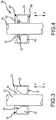
Figure 3 is a cross-sectional view of a first exemplary embodiment of a resistance assembly according to the teachings herein. -
Figure 4 is a cross-sectional view of a second exemplary embodiment of a resistance assembly according to the teachings herein. -
Figure 1 depicts a plunger-type catheter 10 in an undeflected, or neutral, position.Catheter 10 generally includes anelongate body 12, having aproximal end 14 and a deflectabledistal region 16, and ahandle 18 attached toproximal end 14 ofbody 12.Handle 18 includes anactuator 20. As depicted inFigure 1 ,actuator 20 is a plunger that is moveable relative to handle 18 along alongitudinal axis 22 ofhandle 18 in a first direction along arrow A (e.g., distally) that effects deflection ofdistal region 16 from the neutral position, as well as in a second, opposite direction along arrow B (e.g., proximally) that effects return ofdistal region 16 towards the neutral position. For example,catheter 10 can be of the type disclosed in United States provisional application no.61/884,897, filed 30 September 2013 -
Figure 2 depicts additional components ofcatheter 10, namely including apull wire 23 that extends throughbody 12. Pull wire is coupled to distalregion 16 ofbody 12, such that movement ofactuator 20 in the first direction along arrow A effects deflection ofdistal region 16 from the neutral position along a first deflection direction (e.g., arrow C), and such that movement ofactuator 20 in the second direction along arrow B effects return ofdistal region 16 towards the neutral position (e.g., along arrow D). Insofar as the ordinarily skilled artisan will appreciate the use of pull wires in a catheter, a detailed explanation of this aspect of the disclosure need not be, and therefore is not, provided herein. - For purposes of explanation, various embodiments are disclosed herein with reference to a unidirectional catheter. It should be recognized, however, that the disclosed principles are equally applicable in other contexts, including, without limitation, bidirectional catheters. Thus, for example, movement of
actuator 20 in the first direction along arrow A could effect deflection ofdistal region 16 from the neutral position in a first deflection direction (e.g., arrow C inFigure 2 ), while movement ofactuator 20 in the second direction could effect deflection ofdistal region 16 from the neutral position in a second deflection direction, with both the first deflection direction and second deflection direction lying in the same plane. -
Handle 18 also includes a resistance assembly that operates to make it relatively easier for the practitioner to moveactuator 20 in the first direction along arrow A and relatively harder for the practitioner to moveactuator 20 in the second direction along arrow B, no matter what sort of movement ofdistal region 16 is effected thereby (e.g., whether deflection from neutral or return to neutral). Typically, the force exerted by the resistance assembly is a frictional force arising betweenactuator 20 and the resistance assembly. That is, the resistance assembly provides a frictional resistance against the movement ofactuator 20 relative to handle 18, which frictional resistance differs depending on the direction in whichactuator 20 is moving. -
Figure 3 depicts a firstexemplary resistance assembly 24 positionedadjacent actuator 20 and including a constraininghousing 26 and acompression ring 28 positioned aroundactuator 20.Compression ring 28 includes afirst surface 30 and a second,opposite surface 32.First surface 30 includes achamfer 34, whilesecond surface 32 is generally flat (that is, it generally follows the profile of constraining housing 26). Chamfer 34 forms acavity 36 infirst surface 30, such that there is a greater distance betweenfirst surface 30 and constraininghousing 26 than betweensecond surface 32 and constraininghousing 26. -
First surface 30 is oriented in the direction where the lower resistance to movement ofactuator 20 is desired - for example, in the first (e.g., distal) direction that effects deflection ofdistal region 16 from neutral. Thus, asactuator 20 is driven in the first direction along arrow A,compression ring 28 deforms into the space created by chamfer 34 (i.e., cavity 36), thereby reducing both the normal force thatcompression ring 28 exerts onactuator 20 and the frictional resistance to movement ofactuator 20 in the first direction. Conversely, whenactuator 20 is driven in the second direction along arrow B,compression ring 28 is driven against constraininghousing 26, increasing both the normal force thatcompression ring 28 exerts onactuator 20 and the frictional resistance to movement ofactuator 20 in the second direction. As a result, it is easier for the practitioner to moveactuator 20 throughresistance assembly 24 in the first direction than in the second direction. - Moreover,
resistance assembly 24 provides sufficient frictional resistance to any internally-arising restorative forces that would tend to movedistal region 16 towards neutral (e.g., spring forces arising whenpull wire 23 is placed in tension via the movement ofactuator 20 in the direction of arrow A). In this regard,resistance assembly 24 can also be regarded as a self-locking assembly forcatheter 10. -
Figure 4 depicts a secondexemplary resistance assembly 38 positionedadjacent actuator 20.Resistance assembly 38 likewise includes constraininghousing 26, and further includes an annular friction assembly of anannular disk 40 and a compressible member, such as o-ring 42, aboutactuator 20. - Like
compression ring 28,annular disk 40 includes afirst surface 44 and a second,opposite surface 46;first surface 44 includes a beveled/wedge-shaped edge 48 that results in the formation of acavity 50, whilesecond surface 46 is generally flat. O-ring 42 is positioned adjacent first surface 44 (e.g., riding on beveled/wedge-shaped edge 48) withincavity 50. -
First surface 44 is oriented in the direction where the lower resistance to movement ofactuator 20 is desired. Thus, asactuator 20 is driven in the first direction along arrow A, o-ring 42 separates fromannular disk 40, thereby reducing both the normal force that o-ring 42 exerts onactuator 20 and the frictional resistance to movement ofactuator 20 in the first direction. Conversely, whenactuator 20 is driven in the second direction along arrow B, o-ring 42 is driven down beveled/wedge-shapededge 48 until it pinches betweenannular disk 40 andactuator 20, increasing both the normal force that o-ring 42 exerts onactuator 20 and the frictional resistance to movement ofactuator 20 in the second direction. As a result, it is easier for the practitioner to moveactuator 20 throughresistance assembly 38 in the first direction than in the second direction. - Moreover,
resistance assembly 38 provides sufficient frictional resistance to any internally-arising restorative forces that would tend to movedistal region 16 towards neutral (e.g., spring forces arising whenpull wire 23 is placed in tension via the movement ofactuator 20 in the direction of arrow A). In this regard,resistance assembly 38 can also be regarded as a self-locking assembly forcatheter 10. - Although several embodiments of this invention have been described above with a certain degree of particularity, those skilled in the art could make numerous alterations to the disclosed embodiments without departing from the scope of this invention.
- For example, in the embodiments described above, directionally-dependent resistance to movement of
actuator 20 results from differences in the normal (and thus frictional) forces exerted uponactuator 20 depending upon the direction in which it is moving. It is contemplated, however, that the coefficient of friction betweenactuator 20 and the resistance assembly (e.g.,resistance assembly 24 and/or resistance assembly 38) can be directionally-dependent, for example by using a material with anisotropic frictional properties within the resistance assembly (e.g., ascompression ring 28,annular disk 40, or o-ring 42). - In other aspects, the surface of
actuator 20 and/or the surface of the resistance assembly (e.g.,compression ring 28,annular disk 40, and/or o-ring 42) includes a treatment or finish, such as fish scaling, that yields directionally-dependent frictional forces. - Such materials and/or surface treatments can be used either as an alternative to or in addition to the chamfered/beveled/wedge-shaped
edges Figures 3 and 4 and described above that yield directionally-dependent normal forces. - Likewise, o-
ring 42 can be modified from a toroidal shape to further alter the normal force that it exerts onactuator 20 asactuator 20 is moved. For example, o-ring 42 can also include flattened sections, chamfers, slits, and other modifications that increase the normal force that o-ring 42 exerts onactuator 20 asactuator 20 moves in the second direction along arrow B. - As a further example, although the teachings herein are explained in the context of actuators for catheters and other medical devices, the principles can also be applied to other actuators, including, for example, electronic and/or hydraulic linear actuators.
- All directional references (e.g., upper, lower, upward, downward, left, right, leftward, rightward, top, bottom, above, below, vertical, horizontal, clockwise, and counterclockwise) are only used for identification purposes to aid the reader's understanding of the present invention, and do not create limitations, particularly as to the position, orientation, or use of the invention. Joinder references (e.g., attached, coupled, connected, and the like) are to be construed broadly and may include intermediate members between a connection of elements and relative movement between elements. As such, joinder references do not necessarily infer that two elements are directly connected and in fixed relation to each other.
Claims (15)
- A medical device (10), comprising:an elongate body (12) having a proximal end (14) and a deflectable distal region (16);a handle (18) coupled to the proximal end (14) of the elongate body (12) and including an actuator (20) movable relative to the handle (18); anda resistance assembly (24, 38) adjacent the actuator (20), wherein the resistance assembly (24, 38) is configured to exert a force on the actuator (20) that varies according to a direction in which the actuator (20) is moving longitudinally relative to the handle (18).
- The medical device (10) according to claim 1, wherein the force exerted by the resistance assembly (24, 38) is lower when the actuator (20) is moving relative to the handle (18) in a direction that effects deflection of the distal region (14) of the elongate body (12) from neutral and higher when the actuator (20) is moving relative to the handle (18) in a direction that effects return of the distal region (14) of the elongate body (12) towards neutral.
- The medical device (10) according to claim 1, wherein the force exerted by the resistance assembly (24, 38) is lower when the actuator (20) is moving relative to the handle (18) in a direction that effects deflection of the distal region (14) of the elongate body (12) from neutral in a first deflection direction and higher when the actuator (20) is moving relative to the handle (18) in a direction that effects deflection of the distal region (14) of the elongate body (12) from neutral in a second deflection direction opposite the first deflection direction.
- The medical device (10) according to claim 1, wherein the actuator (20) is movable relative to the handle (18) along a longitudinal axis thereof; and
wherein the resistance assembly (24, 38) exerts a first frictional force on the actuator (20) when the actuator (20) is moved in a first direction (A) along the longitudinal axis of the handle (18) and a second frictional force on the actuator (20) when the actuator (20) is moved in a second direction (B) along the longitudinal axis of the handle (18),
wherein the second direction (B) is opposite the first direction (A), and
wherein the second frictional force is greater than the first frictional force. - The medical device (10) according to any preceding claim, wherein the resistance assembly (24, 38) comprises a member made of a material having anisotropic frictional properties.
- The medical device (10) according to any preceding claim, wherein at least one of a surface of the actuator (20) facing the resistance assembly (24, 38) and a surface of the resistance assembly (24, 38) facing the actuator (20) includes a finish that yields directionally-dependent frictional forces.
- The medical device (10) according to any preceding claim, wherein the resistance assembly (24, 38) comprises an annular member (28, 40) positioned around the actuator (20), wherein the annular member (28, 40) includes a first surface (30, 44) and a second surface (32, 46), and wherein the first surface (30, 44) of the annular member (28, 34) includes a cavity (34, 50).
- The medical device (10) according to claim 7, wherein the resistance assembly (38) further comprises a compressible member (42) positioned around the actuator (20) adjacent the first surface (44) of the annular member (40) and within the cavity (34),
wherein movement of the actuator (20) in a first direction (A) separates the compressible member (42) from the first surface (44) of the annular member (40), thereby minimizing resistance to movement of the actuator (20) in the first direction (A), and
wherein movement of the actuator (20) in a second direction (B) opposite the first direction (A) drives the compressible member (42) against the first surface (44) of the annular member (40), thereby maximizing resistance to movement of the actuator (20) in the second direction (B). - The medical device (10) according to claim 8, wherein the compressible member (42) comprises an o-ring having a non-circular cross-sectional shape.
- The medical device (10) according to any of claims 7-9, wherein the resistance assembly (24, 38) further comprises a constraining housing (26), and wherein the annular member (28, 40) is positioned within the constraining housing (26).
- The medical device (1) according to any preceding claim, further comprising a pull wire (23) extending through the body (12),
wherein the pull wire (23) is coupled to the distal region (14) of the body (12) to effect deflection thereof,
wherein moving the actuator (20) in the first direction (A) effects deflection of the body (12) from neutral in a first deflection direction. - The medical device (10) according to claim 11, wherein moving the actuator (20) in the second direction (B) effects deflection of the body (12) from neutral in a second deflection direction.
- A resistance assembly (24, 38) to impart resistance to movement of an actuator (20) for a medical device (10), the resistance assembly (24, 38) comprising:a constraining housing (26); andan annular friction assembly (28, 40) positioned within the housing (26),wherein a lower force is required to pass the actuator (20) through the annular friction assembly (28, 40) in a first direction (A) than to pass the actuator (20) through the annular friction assembly (28, 40) in a second direction (B).
- The resistance assembly (24, 38) according to claim 13, wherein the annular friction assembly (28, 40) comprises a material having anisotropic frictional properties.
- The resistance assembly (24, 38) according to claims 13 or 14, wherein the annular friction assembly (24, 38) comprises one of:(a) an annular compression ring (28) having a first surface (30) and a second surface (32), wherein the first surface (30) includes a cavity (34) such that there is greater distance between the first surface (30) of the compression ring (28) and the constraining housing (26) than between the second surface (32) of the compression ring (28) and the constraining housing (26); or(b) an annular disk (40) having a first surface (44) and a second surface (46), wherein the first surface (44) includes a wedge-shaped portion; anda compressible member (42) riding on the wedge-shaped portion,
such that, when the actuator (20) is passed through the annular friction assembly (38) in the first direction (A), the compressible member (42) separates from the annular disk (40), and when the actuator (20) is passed through the annular friction assembly (38) in the second direction (B), the compressible member (42) is wedged between the actuator (20) and the annular disk (40).
Applications Claiming Priority (2)
| Application Number | Priority Date | Filing Date | Title |
|---|---|---|---|
| US201361919095P | 2013-12-20 | 2013-12-20 | |
| PCT/US2014/070762 WO2015095283A1 (en) | 2013-12-20 | 2014-12-17 | Actuator restraining assembly for medical device |
Publications (2)
| Publication Number | Publication Date |
|---|---|
| EP3062861A1 EP3062861A1 (en) | 2016-09-07 |
| EP3062861B1 true EP3062861B1 (en) | 2018-03-21 |
Family
ID=52345550
Family Applications (1)
| Application Number | Title | Priority Date | Filing Date |
|---|---|---|---|
| EP14825538.3A Active EP3062861B1 (en) | 2013-12-20 | 2014-12-17 | Actuator restraining assembly for medical device |
Country Status (5)
| Country | Link |
|---|---|
| US (1) | US10195397B2 (en) |
| EP (1) | EP3062861B1 (en) |
| JP (2) | JP6286051B2 (en) |
| CN (1) | CN105828867B (en) |
| WO (1) | WO2015095283A1 (en) |
Family Cites Families (11)
| Publication number | Priority date | Publication date | Assignee | Title |
|---|---|---|---|---|
| AU665358B2 (en) | 1991-08-28 | 1996-01-04 | Medtronic, Inc. | Steerable stylet and manipulative handle assembly |
| JPH0533736U (en) * | 1991-10-07 | 1993-05-07 | テルモ株式会社 | catheter |
| US5242441A (en) * | 1992-02-24 | 1993-09-07 | Boaz Avitall | Deflectable catheter with rotatable tip electrode |
| US6623473B1 (en) * | 1998-06-04 | 2003-09-23 | Biosense Webster, Inc. | Injection catheter with multi-directional delivery injection needle |
| JP4566390B2 (en) * | 1999-11-12 | 2010-10-20 | バイオセンス・ウエブスター・インコーポレーテツド | Infusion catheter |
| DE602004011608T2 (en) | 2003-03-28 | 2009-01-29 | C.R. Bard, Inc. | Catheter with braided mesh |
| EP1905376B1 (en) * | 2003-03-28 | 2010-09-29 | C.R.Bard, Inc. | Braided mesh catheter |
| US7722302B2 (en) * | 2006-01-13 | 2010-05-25 | Oceaneering International, Inc. | Self locking tensioner |
| JP4224123B1 (en) | 2008-05-20 | 2009-02-12 | 日本ライフライン株式会社 | Catheter handle |
| JP4224122B1 (en) * | 2008-05-20 | 2009-02-12 | 日本ライフライン株式会社 | Catheter handle |
| JP5429878B2 (en) | 2010-05-12 | 2014-02-26 | 日本ライフライン株式会社 | Catheter handle |
-
2014
- 2014-12-17 WO PCT/US2014/070762 patent/WO2015095283A1/en not_active Ceased
- 2014-12-17 US US14/573,115 patent/US10195397B2/en active Active
- 2014-12-17 JP JP2016539933A patent/JP6286051B2/en active Active
- 2014-12-17 EP EP14825538.3A patent/EP3062861B1/en active Active
- 2014-12-17 CN CN201480067800.3A patent/CN105828867B/en active Active
-
2017
- 2017-08-18 JP JP2017158256A patent/JP6603274B2/en active Active
Also Published As
| Publication number | Publication date |
|---|---|
| EP3062861A1 (en) | 2016-09-07 |
| JP2017503556A (en) | 2017-02-02 |
| WO2015095283A1 (en) | 2015-06-25 |
| CN105828867B (en) | 2019-02-01 |
| US20150174369A1 (en) | 2015-06-25 |
| JP2017221716A (en) | 2017-12-21 |
| JP6603274B2 (en) | 2019-11-06 |
| US10195397B2 (en) | 2019-02-05 |
| CN105828867A (en) | 2016-08-03 |
| JP6286051B2 (en) | 2018-02-28 |
Similar Documents
| Publication | Publication Date | Title |
|---|---|---|
| US11420020B2 (en) | Medical device including a variable torque assembly for device deflection | |
| US10737062B2 (en) | Auto lock for catheter handle | |
| CN109069799B (en) | Mapping adjustable loop catheter handle | |
| EP2002859B1 (en) | A deflectable stylet | |
| JP2017516604A (en) | Long maneuverable device for insertion into the subject's body | |
| US10576249B2 (en) | Medical device including an actuator restraining assembly | |
| WO1995005116A1 (en) | Deflectable catheter | |
| US11517714B2 (en) | Medical device including an actuator restraining assembly | |
| US12042609B2 (en) | Medical device including an actuator restraining assembly | |
| US10195397B2 (en) | Actuator restraining assembly for medical device | |
| US11918762B2 (en) | Reduced actuation force electrophysiology catheter handle | |
| EP3113826B1 (en) | Mechanism for controlling unintentional movement of components |
Legal Events
| Date | Code | Title | Description |
|---|---|---|---|
| PUAI | Public reference made under article 153(3) epc to a published international application that has entered the european phase |
Free format text: ORIGINAL CODE: 0009012 |
|
| 17P | Request for examination filed |
Effective date: 20160531 |
|
| AK | Designated contracting states |
Kind code of ref document: A1 Designated state(s): AL AT BE BG CH CY CZ DE DK EE ES FI FR GB GR HR HU IE IS IT LI LT LU LV MC MK MT NL NO PL PT RO RS SE SI SK SM TR |
|
| AX | Request for extension of the european patent |
Extension state: BA ME |
|
| DAX | Request for extension of the european patent (deleted) | ||
| 17Q | First examination report despatched |
Effective date: 20170502 |
|
| GRAP | Despatch of communication of intention to grant a patent |
Free format text: ORIGINAL CODE: EPIDOSNIGR1 |
|
| RIC1 | Information provided on ipc code assigned before grant |
Ipc: A61M 25/01 20060101AFI20170918BHEP |
|
| INTG | Intention to grant announced |
Effective date: 20171012 |
|
| INTG | Intention to grant announced |
Effective date: 20171018 |
|
| GRAS | Grant fee paid |
Free format text: ORIGINAL CODE: EPIDOSNIGR3 |
|
| GRAA | (expected) grant |
Free format text: ORIGINAL CODE: 0009210 |
|
| AK | Designated contracting states |
Kind code of ref document: B1 Designated state(s): AL AT BE BG CH CY CZ DE DK EE ES FI FR GB GR HR HU IE IS IT LI LT LU LV MC MK MT NL NO PL PT RO RS SE SI SK SM TR |
|
| REG | Reference to a national code |
Ref country code: GB Ref legal event code: FG4D |
|
| REG | Reference to a national code |
Ref country code: CH Ref legal event code: EP |
|
| REG | Reference to a national code |
Ref country code: AT Ref legal event code: REF Ref document number: 980443 Country of ref document: AT Kind code of ref document: T Effective date: 20180415 |
|
| REG | Reference to a national code |
Ref country code: IE Ref legal event code: FG4D |
|
| REG | Reference to a national code |
Ref country code: DE Ref legal event code: R096 Ref document number: 602014022764 Country of ref document: DE |
|
| REG | Reference to a national code |
Ref country code: NL Ref legal event code: MP Effective date: 20180321 |
|
| PG25 | Lapsed in a contracting state [announced via postgrant information from national office to epo] |
Ref country code: FI Free format text: LAPSE BECAUSE OF FAILURE TO SUBMIT A TRANSLATION OF THE DESCRIPTION OR TO PAY THE FEE WITHIN THE PRESCRIBED TIME-LIMIT Effective date: 20180321 Ref country code: NO Free format text: LAPSE BECAUSE OF FAILURE TO SUBMIT A TRANSLATION OF THE DESCRIPTION OR TO PAY THE FEE WITHIN THE PRESCRIBED TIME-LIMIT Effective date: 20180621 Ref country code: CY Free format text: LAPSE BECAUSE OF FAILURE TO SUBMIT A TRANSLATION OF THE DESCRIPTION OR TO PAY THE FEE WITHIN THE PRESCRIBED TIME-LIMIT Effective date: 20180321 Ref country code: LT Free format text: LAPSE BECAUSE OF FAILURE TO SUBMIT A TRANSLATION OF THE DESCRIPTION OR TO PAY THE FEE WITHIN THE PRESCRIBED TIME-LIMIT Effective date: 20180321 Ref country code: HR Free format text: LAPSE BECAUSE OF FAILURE TO SUBMIT A TRANSLATION OF THE DESCRIPTION OR TO PAY THE FEE WITHIN THE PRESCRIBED TIME-LIMIT Effective date: 20180321 |
|
| REG | Reference to a national code |
Ref country code: LT Ref legal event code: MG4D |
|
| REG | Reference to a national code |
Ref country code: AT Ref legal event code: MK05 Ref document number: 980443 Country of ref document: AT Kind code of ref document: T Effective date: 20180321 |
|
| PG25 | Lapsed in a contracting state [announced via postgrant information from national office to epo] |
Ref country code: GR Free format text: LAPSE BECAUSE OF FAILURE TO SUBMIT A TRANSLATION OF THE DESCRIPTION OR TO PAY THE FEE WITHIN THE PRESCRIBED TIME-LIMIT Effective date: 20180622 Ref country code: BG Free format text: LAPSE BECAUSE OF FAILURE TO SUBMIT A TRANSLATION OF THE DESCRIPTION OR TO PAY THE FEE WITHIN THE PRESCRIBED TIME-LIMIT Effective date: 20180621 Ref country code: RS Free format text: LAPSE BECAUSE OF FAILURE TO SUBMIT A TRANSLATION OF THE DESCRIPTION OR TO PAY THE FEE WITHIN THE PRESCRIBED TIME-LIMIT Effective date: 20180321 Ref country code: SE Free format text: LAPSE BECAUSE OF FAILURE TO SUBMIT A TRANSLATION OF THE DESCRIPTION OR TO PAY THE FEE WITHIN THE PRESCRIBED TIME-LIMIT Effective date: 20180321 Ref country code: LV Free format text: LAPSE BECAUSE OF FAILURE TO SUBMIT A TRANSLATION OF THE DESCRIPTION OR TO PAY THE FEE WITHIN THE PRESCRIBED TIME-LIMIT Effective date: 20180321 |
|
| PG25 | Lapsed in a contracting state [announced via postgrant information from national office to epo] |
Ref country code: PL Free format text: LAPSE BECAUSE OF FAILURE TO SUBMIT A TRANSLATION OF THE DESCRIPTION OR TO PAY THE FEE WITHIN THE PRESCRIBED TIME-LIMIT Effective date: 20180321 Ref country code: EE Free format text: LAPSE BECAUSE OF FAILURE TO SUBMIT A TRANSLATION OF THE DESCRIPTION OR TO PAY THE FEE WITHIN THE PRESCRIBED TIME-LIMIT Effective date: 20180321 Ref country code: ES Free format text: LAPSE BECAUSE OF FAILURE TO SUBMIT A TRANSLATION OF THE DESCRIPTION OR TO PAY THE FEE WITHIN THE PRESCRIBED TIME-LIMIT Effective date: 20180321 Ref country code: RO Free format text: LAPSE BECAUSE OF FAILURE TO SUBMIT A TRANSLATION OF THE DESCRIPTION OR TO PAY THE FEE WITHIN THE PRESCRIBED TIME-LIMIT Effective date: 20180321 Ref country code: NL Free format text: LAPSE BECAUSE OF FAILURE TO SUBMIT A TRANSLATION OF THE DESCRIPTION OR TO PAY THE FEE WITHIN THE PRESCRIBED TIME-LIMIT Effective date: 20180321 Ref country code: AL Free format text: LAPSE BECAUSE OF FAILURE TO SUBMIT A TRANSLATION OF THE DESCRIPTION OR TO PAY THE FEE WITHIN THE PRESCRIBED TIME-LIMIT Effective date: 20180321 |
|
| PG25 | Lapsed in a contracting state [announced via postgrant information from national office to epo] |
Ref country code: SK Free format text: LAPSE BECAUSE OF FAILURE TO SUBMIT A TRANSLATION OF THE DESCRIPTION OR TO PAY THE FEE WITHIN THE PRESCRIBED TIME-LIMIT Effective date: 20180321 Ref country code: AT Free format text: LAPSE BECAUSE OF FAILURE TO SUBMIT A TRANSLATION OF THE DESCRIPTION OR TO PAY THE FEE WITHIN THE PRESCRIBED TIME-LIMIT Effective date: 20180321 Ref country code: SM Free format text: LAPSE BECAUSE OF FAILURE TO SUBMIT A TRANSLATION OF THE DESCRIPTION OR TO PAY THE FEE WITHIN THE PRESCRIBED TIME-LIMIT Effective date: 20180321 Ref country code: CZ Free format text: LAPSE BECAUSE OF FAILURE TO SUBMIT A TRANSLATION OF THE DESCRIPTION OR TO PAY THE FEE WITHIN THE PRESCRIBED TIME-LIMIT Effective date: 20180321 |
|
| PG25 | Lapsed in a contracting state [announced via postgrant information from national office to epo] |
Ref country code: PT Free format text: LAPSE BECAUSE OF FAILURE TO SUBMIT A TRANSLATION OF THE DESCRIPTION OR TO PAY THE FEE WITHIN THE PRESCRIBED TIME-LIMIT Effective date: 20180723 |
|
| REG | Reference to a national code |
Ref country code: DE Ref legal event code: R097 Ref document number: 602014022764 Country of ref document: DE |
|
| PLBE | No opposition filed within time limit |
Free format text: ORIGINAL CODE: 0009261 |
|
| STAA | Information on the status of an ep patent application or granted ep patent |
Free format text: STATUS: NO OPPOSITION FILED WITHIN TIME LIMIT |
|
| PG25 | Lapsed in a contracting state [announced via postgrant information from national office to epo] |
Ref country code: DK Free format text: LAPSE BECAUSE OF FAILURE TO SUBMIT A TRANSLATION OF THE DESCRIPTION OR TO PAY THE FEE WITHIN THE PRESCRIBED TIME-LIMIT Effective date: 20180321 |
|
| 26N | No opposition filed |
Effective date: 20190102 |
|
| PG25 | Lapsed in a contracting state [announced via postgrant information from national office to epo] |
Ref country code: SI Free format text: LAPSE BECAUSE OF FAILURE TO SUBMIT A TRANSLATION OF THE DESCRIPTION OR TO PAY THE FEE WITHIN THE PRESCRIBED TIME-LIMIT Effective date: 20180321 |
|
| REG | Reference to a national code |
Ref country code: CH Ref legal event code: PL |
|
| PG25 | Lapsed in a contracting state [announced via postgrant information from national office to epo] |
Ref country code: MC Free format text: LAPSE BECAUSE OF FAILURE TO SUBMIT A TRANSLATION OF THE DESCRIPTION OR TO PAY THE FEE WITHIN THE PRESCRIBED TIME-LIMIT Effective date: 20180321 Ref country code: LU Free format text: LAPSE BECAUSE OF NON-PAYMENT OF DUE FEES Effective date: 20181217 |
|
| REG | Reference to a national code |
Ref country code: IE Ref legal event code: MM4A |
|
| REG | Reference to a national code |
Ref country code: BE Ref legal event code: MM Effective date: 20181231 |
|
| PG25 | Lapsed in a contracting state [announced via postgrant information from national office to epo] |
Ref country code: IE Free format text: LAPSE BECAUSE OF NON-PAYMENT OF DUE FEES Effective date: 20181217 |
|
| PG25 | Lapsed in a contracting state [announced via postgrant information from national office to epo] |
Ref country code: BE Free format text: LAPSE BECAUSE OF NON-PAYMENT OF DUE FEES Effective date: 20181231 |
|
| PG25 | Lapsed in a contracting state [announced via postgrant information from national office to epo] |
Ref country code: CH Free format text: LAPSE BECAUSE OF NON-PAYMENT OF DUE FEES Effective date: 20181231 Ref country code: LI Free format text: LAPSE BECAUSE OF NON-PAYMENT OF DUE FEES Effective date: 20181231 |
|
| PG25 | Lapsed in a contracting state [announced via postgrant information from national office to epo] |
Ref country code: MT Free format text: LAPSE BECAUSE OF NON-PAYMENT OF DUE FEES Effective date: 20181217 |
|
| PG25 | Lapsed in a contracting state [announced via postgrant information from national office to epo] |
Ref country code: TR Free format text: LAPSE BECAUSE OF FAILURE TO SUBMIT A TRANSLATION OF THE DESCRIPTION OR TO PAY THE FEE WITHIN THE PRESCRIBED TIME-LIMIT Effective date: 20180321 |
|
| PG25 | Lapsed in a contracting state [announced via postgrant information from national office to epo] |
Ref country code: MK Free format text: LAPSE BECAUSE OF NON-PAYMENT OF DUE FEES Effective date: 20180321 Ref country code: HU Free format text: LAPSE BECAUSE OF FAILURE TO SUBMIT A TRANSLATION OF THE DESCRIPTION OR TO PAY THE FEE WITHIN THE PRESCRIBED TIME-LIMIT; INVALID AB INITIO Effective date: 20141217 |
|
| PG25 | Lapsed in a contracting state [announced via postgrant information from national office to epo] |
Ref country code: IS Free format text: LAPSE BECAUSE OF FAILURE TO SUBMIT A TRANSLATION OF THE DESCRIPTION OR TO PAY THE FEE WITHIN THE PRESCRIBED TIME-LIMIT Effective date: 20180721 |
|
| P01 | Opt-out of the competence of the unified patent court (upc) registered |
Effective date: 20230616 |
|
| REG | Reference to a national code |
Ref country code: DE Ref legal event code: R082 Ref document number: 602014022764 Country of ref document: DE Representative=s name: ALPSPITZ IP ALLGAYER UND PARTNER PATENTANWAELT, DE |
|
| PGFP | Annual fee paid to national office [announced via postgrant information from national office to epo] |
Ref country code: DE Payment date: 20251118 Year of fee payment: 12 |
|
| PGFP | Annual fee paid to national office [announced via postgrant information from national office to epo] |
Ref country code: GB Payment date: 20251113 Year of fee payment: 12 |
|
| PGFP | Annual fee paid to national office [announced via postgrant information from national office to epo] |
Ref country code: IT Payment date: 20251212 Year of fee payment: 12 |
|
| PGFP | Annual fee paid to national office [announced via postgrant information from national office to epo] |
Ref country code: FR Payment date: 20251111 Year of fee payment: 12 |