EP3062591A1 - Locking foot - Google Patents
Locking foot Download PDFInfo
- Publication number
- EP3062591A1 EP3062591A1 EP16157735.8A EP16157735A EP3062591A1 EP 3062591 A1 EP3062591 A1 EP 3062591A1 EP 16157735 A EP16157735 A EP 16157735A EP 3062591 A1 EP3062591 A1 EP 3062591A1
- Authority
- EP
- European Patent Office
- Prior art keywords
- foldable foot
- locking
- mounting plate
- foot
- test
- Prior art date
- Legal status (The legal status is an assumption and is not a legal conclusion. Google has not performed a legal analysis and makes no representation as to the accuracy of the status listed.)
- Withdrawn
Links
Images


Classifications
-
- F—MECHANICAL ENGINEERING; LIGHTING; HEATING; WEAPONS; BLASTING
- F16—ENGINEERING ELEMENTS AND UNITS; GENERAL MEASURES FOR PRODUCING AND MAINTAINING EFFECTIVE FUNCTIONING OF MACHINES OR INSTALLATIONS; THERMAL INSULATION IN GENERAL
- F16M—FRAMES, CASINGS OR BEDS OF ENGINES, MACHINES OR APPARATUS, NOT SPECIFIC TO ENGINES, MACHINES OR APPARATUS PROVIDED FOR ELSEWHERE; STANDS; SUPPORTS
- F16M11/00—Stands or trestles as supports for apparatus or articles placed thereon ; Stands for scientific apparatus such as gravitational force meters
- F16M11/20—Undercarriages with or without wheels
- F16M11/24—Undercarriages with or without wheels changeable in height or length of legs, also for transport only, e.g. by means of tubes screwed into each other
- F16M11/38—Undercarriages with or without wheels changeable in height or length of legs, also for transport only, e.g. by means of tubes screwed into each other by folding, e.g. pivoting or scissors tong mechanisms
-
- F—MECHANICAL ENGINEERING; LIGHTING; HEATING; WEAPONS; BLASTING
- F16—ENGINEERING ELEMENTS AND UNITS; GENERAL MEASURES FOR PRODUCING AND MAINTAINING EFFECTIVE FUNCTIONING OF MACHINES OR INSTALLATIONS; THERMAL INSULATION IN GENERAL
- F16M—FRAMES, CASINGS OR BEDS OF ENGINES, MACHINES OR APPARATUS, NOT SPECIFIC TO ENGINES, MACHINES OR APPARATUS PROVIDED FOR ELSEWHERE; STANDS; SUPPORTS
- F16M13/00—Other supports for positioning apparatus or articles; Means for steadying hand-held apparatus or articles
- F16M13/005—Other supports for positioning apparatus or articles; Means for steadying hand-held apparatus or articles integral with the apparatus or articles to be supported
-
- G—PHYSICS
- G01—MEASURING; TESTING
- G01D—MEASURING NOT SPECIALLY ADAPTED FOR A SPECIFIC VARIABLE; ARRANGEMENTS FOR MEASURING TWO OR MORE VARIABLES NOT COVERED IN A SINGLE OTHER SUBCLASS; TARIFF METERING APPARATUS; MEASURING OR TESTING NOT OTHERWISE PROVIDED FOR
- G01D11/00—Component parts of measuring arrangements not specially adapted for a specific variable
- G01D11/30—Supports specially adapted for an instrument; Supports specially adapted for a set of instruments
-
- H—ELECTRICITY
- H05—ELECTRIC TECHNIQUES NOT OTHERWISE PROVIDED FOR
- H05K—PRINTED CIRCUITS; CASINGS OR CONSTRUCTIONAL DETAILS OF ELECTRIC APPARATUS; MANUFACTURE OF ASSEMBLAGES OF ELECTRICAL COMPONENTS
- H05K5/00—Casings, cabinets or drawers for electric apparatus
- H05K5/02—Details
- H05K5/0217—Mechanical details of casings
- H05K5/0234—Feet; Stands; Pedestals, e.g. wheels for moving casing on floor
-
- F—MECHANICAL ENGINEERING; LIGHTING; HEATING; WEAPONS; BLASTING
- F16—ENGINEERING ELEMENTS AND UNITS; GENERAL MEASURES FOR PRODUCING AND MAINTAINING EFFECTIVE FUNCTIONING OF MACHINES OR INSTALLATIONS; THERMAL INSULATION IN GENERAL
- F16M—FRAMES, CASINGS OR BEDS OF ENGINES, MACHINES OR APPARATUS, NOT SPECIFIC TO ENGINES, MACHINES OR APPARATUS PROVIDED FOR ELSEWHERE; STANDS; SUPPORTS
- F16M2200/00—Details of stands or supports
- F16M2200/02—Locking means
- F16M2200/021—Locking means for rotational movement
- F16M2200/024—Locking means for rotational movement by positive interaction, e.g. male-female connections
-
- F—MECHANICAL ENGINEERING; LIGHTING; HEATING; WEAPONS; BLASTING
- F16—ENGINEERING ELEMENTS AND UNITS; GENERAL MEASURES FOR PRODUCING AND MAINTAINING EFFECTIVE FUNCTIONING OF MACHINES OR INSTALLATIONS; THERMAL INSULATION IN GENERAL
- F16M—FRAMES, CASINGS OR BEDS OF ENGINES, MACHINES OR APPARATUS, NOT SPECIFIC TO ENGINES, MACHINES OR APPARATUS PROVIDED FOR ELSEWHERE; STANDS; SUPPORTS
- F16M2200/00—Details of stands or supports
- F16M2200/08—Foot or support base
Definitions
- the present disclosure relates to test and measurement instruments, and more particularly to foot structures for test and measurement instruments.
- Foot structures may include fixed parts, such as a pad that provides cushioning or a non-slip contact point for the device. Foot structures may also include moveable parts that operate to raise the device to a desired height, or to tilt the device to a desired angle, in order to achieve one or more advantages. For example, a device user may wish to tilt the device to a desired angle in order to improve ergonomics, reduce glare on the device's display, or improve accessibility of the device's user interface.
- a flip foot usually has a fixed pivot point at one end, and the foot rotates about the pivot point from a closed position to an open position.
- a pair of flip feet are placed on the bottom surface of a device, near its front edge. When the device sits on a relatively level horizontal surface and the feet are in the closed position, the front surface of the device will be in a generally vertical orientation.
- a user generally lifts up the front edge of the device and moves the flip feet to the open position. When in the open position, the flip feet prop up the device causing the front surface of the device to be at a set angle from vertical.
- This disclosure uses the terms “flip foot,” “foldable foot,” or simply “foot” interchangeably to refer to this type of foot structure.
- a locking foldable foot includes a mounting plate, a first member having a proximal end and a distal end, and a second member having a proximal end and a distal end.
- the proximal end of the first member is attached to the mounting plate at a pivot.
- the second member is coupled to the first member and is structured to move parallel to the first member.
- the proximal end of the second member is structured to be capable of engaging the mounting plate to prevent rotation of the first and second members about the pivot.
- the locking function of the locking foldable foot is weight-activated.
- the second member in response to a force being applied to the distal end of the second member, the second member moves proximally toward the pivot so that the proximal end of the second member engages with the mounting plate.
- the locking foldable foot also includes a spring coupled between the first and second member that acts to cause the second member to move distally away from the pivot so that the proximate end of the second member dis-engages the mounting plate when the force is removed from the distal end of the second member.
- a test and measurement instrument includes a locking foldable foot, as described above, mounted to the test and measurement instrument.
- the second member moves proximally toward the pivot so that the proximal end of the second member engages the mounting plate, and when the weight of the test and measurement instrument is removed from the foot, the second member moves distally away from the pivot so that the proximal end of the second member dis-engages the mounting plate.
- a method of preventing unintentional closure of a foldable foot on a test and measurement instrument includes locking the foldable foot in an open position in response to the weight of the test and measurement instrument being applied to the foldable foot. In some embodiments, the method also includes unlocking the foldable foot from the open position in response to the weight of the test and measurement instrument being removed from the foldable foot.
- a test and measurement instrument typically has at least a pair of foldable feet located substantially at the two front corners of the bottom surface of the instrument.
- the foldable feet When the foldable feet are in a closed position, the bottom surface of the instrument is substantially level, parallel to the surface upon which the instrument is resting, such as a desk or workbench. In this position, the front face of the instrument is substantially perpendicular to the work surface. If the instrument user wants to change, for example, the viewing angle of a display on the front face of the instrument, the user typically lifts the front edge of the instrument up off the work surface to a height sufficient to allow the user to unfold each of the foldable feet into an open position, and then sets the instrument back down onto the open feet.
- the foldable feet are susceptible to unexpectedly collapsing to the closed position, or partially collapsing, when the instrument is tipped or moved in certain ways. Specifically, the foldable feet are prone to unintentional closure when there is a sufficient back to front, lateral force applied to the instrument. Such forces can occur in normal use conditions of the instrument. For example, a user may need to tilt the instrument forward to verify or make a cable connection on the back of the instrument. When this forward tipping of the instrument exceeds a certain angle, the foldable feet are prone to collapse into their closed position. Or, a user may need to pull the instrument forward across the work surface toward herself to better reach the instrument's controls.
- foldable feet often have a non-slip coating at the end, or since the work surface itself may have non-slip properties, for example by being covered with an electrostatic discharge protective mat, dragging the instrument toward the user may cause the foldable feet to catch on the work surface and therefore collapse into their closed position.
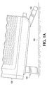
- FIG. 1A is a side elevation view of a locking foldable foot 120, and a foldable foot 140, mounted to the bottom surface of a test and measurement instrument 100, according to embodiments of the invention.
- the foldable feet 120, 140 are in an open configuration and rest on a work surface 160.
- the foldable feet 120, 140 are shown mounted to the instrument 100 in what would be typical mounting locations: the locking foldable foot 120 is shown mounted near the front edge of the bottom surface of the test and measurement instrument 100, and the foldable foot 140 is mounted near the back edge of the bottom surface of the instrument 100.
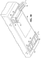
- FIG. 1B is a bottom perspective view of the instrument 100 showing a first set of the foldable feet 120, 140 (front, rear) in a folded or closed configuration, and a second set of the foldable feet 120, 140 (front, rear) in the open configuration.
- the locking foldable foot 120 includes a mounting plate 122.
- the mounting plate 122 is structured to be mountable to an apparatus, such as the instrument 100.
- the mounting plate 122 may have holes to allow the locking foldable foot 120 to be mounted to the instrument 100 with screws or other fasteners.
- the mounting plate 122 may be structured to slide or snap into a slot in the chassis or housing of the instrument 100.
- FIG. 2 is a cross-sectional view taken along lines 2-2 in FIG. 1B , showing the locking foldable foot 120 in a closed configuration in side elevation view according to embodiments of the invention.
- FIG. 3 is a cross-sectional view taken along lines 3-3 in FIG. 1B , showing the locking foldable foot 120 in an open configuration according to embodiments of the invention.
- the locking foldable foot 120 includes a first member 124 and a second member 128.
- the first member 124 has a proximal end and a distal end.
- the proximal end of the first member 124 is attached to the mounting plate 122 at a pivot 126.
- the first member 124 rotates between a closed position, as shown in FIG. 2 , and an open position, as shown in FIG. 3 .
- the first member 124 fits into a foot-receiving recess 132 in the mounting plate 122.
- FIGS. 1A , 1B , and 2-3 illustrate the rear foldable foot 140 as also being attached to the same mounting plate 122, and also folding into the same foot-receiving recess 132 in the mounting plate 122 when in the closed configuration.
- the foldable foot 140 is completely separable and independent from the locking foldable foot 120, and may instead be manufactured as its own assembly. Thus, the remainder of this disclosure will focus on details of the locking foldable foot 120.
- the locking foldable foot 120 includes a first detent for resisting rotation of the first member 124 when in the closed position, and a second detent for resisting rotation of the first member when in the open position.
- a “detent” is a device or mechanism for positioning and holding one mechanical part in relation to another-here, a mechanism for holding the first member 124 in relation to the mounting plate 122—so that the mechanism can be released by sufficient force applied to one of the parts.
- the first detent is effected through the engagement of a tang 123 in the mounting plate 122 with a first recess 125a in the first member 124
- the second detent is effected through the engagement of the tang 123 with a second recess 125b in the first member 124.
- the second member 128 of the locking foldable foot 120 like the first member 124, also has a proximal end and a distal end.
- the second member 128 is coupled to the first member 124 and is structured to move parallel to the first member 124. For example, when the first member 124 rotates about the pivot 126 from the closed position to the open position, the second member 128 also rotates about the pivot 126, in parallel with the first member 124.
- the proximal end of the second member 126 is structured to be capable of engaging with the mounting plate 122 to prevent rotation of the first and second members 124, 128 about the pivot 126.
- the distal end of the second member 128 is structured to be capable of resting on the work surface 160.
- the distal end of the second member includes a non-slip pad 129.
- the second member 128 is coupled to the first member 124 in such a way that the second member 128 is able to move, relative to the first member 124, along the proximal-distal axis.
- the second member 128 is coupled to the first member 124 by being structured to telescope with the first member 124.
- the second member 128 is illustrated as telescoping into the first member 124, but in alternative embodiments, the first member 124 may telescope into the second member 128.
- the second member 128 is coupled to the first member 124 by being structured to slide along a track in the first member 124.
- the second member 128 is capable of moving, relative to the first member 124, along the proximal-distal axis, in preferred embodiments, when the first member 124 is in the open position, in response to a force being applied to the distal end of the second member 128, the second member 128 moves proximally toward the pivot 126 so that the proximal end of the second member 128 engages the mounting plate 122, thereby locking the locking foldable foot 120 into the open position by preventing rotation of the first and second members 124, 128 about the pivot 126.
- the proximal end of the second member 128 is illustrated as engaging a surface 122a of the mounting plate 122.
- the tab-like structure at the proximal end of the second member 128 substantially fits into the cavity in the mounting plate 122 formed essentially by the surface 122a and the tang 123 in order to lock the first and second members 124, 128 into position and prevent the locking foldable foot 120 from collapsing back into the closed configuration.
- FIGS. 2-8 illustrate the second member 128 as a single-piece of material, so that the force applied to the distal end of the second member 128 is directly translated to engagement of the proximal end of the second member 128 with the mounting plate.
- the second member 128 can comprise multiple pieces, such as one piece for the distal end, mechanically linked to another piece for the proximal end.
- the above-described locking mechanism of the locking foldable foot 120 is weight-activated. That is, because the locking foldable foot 120 will ordinarily be mounted to the bottom surface of the instrument 100, when a user lifts the front edge of the instrument 100 up, flips the locking foldable foot 120 into the open position, and then sets the instrument 100 back down onto the foot 120, the force applied to the distal end of the second member 128 is the weight of the instrument 100. Thus, the locking foldable foot 120 is automatically locked in place when the instrument 100 is resting on the foot 120 in the open configuration. This feature is highly advantageous since the user does not have to remember to engage a lock; rather, simply placing the instrument 100 back down onto the work surface 160 automatically engages the locking function.
- the above-described locking mechanism of the locking foldable foot 120 is also automatically dis-engaged when the weight of the instrument 100 is removed from the locking foldable foot 120. That is, when the force, such as the weight of the instrument 100, is removed from the distal end of the second member 128, the second member moves distally away from the pivot 126 so that the proximal end of the second member 128 dis-engages the mounting plate 122.
- the locking foldable foot 120 includes a spring 130 coupled between the first and second members 124, 128.
- the spring 130 acts to cause the second member 128 to move distally away from the pivot 126 when the force-e.g. the weight of the instrument 100-is removed from the distal end of the second member 128.
- the spring 130 is selected to ensure that the second member 128 will always snap back distally-thereby dis-engaging the locking function-when the weight of the instrument 100 is removed from the locking foldable foot 120. The user is then free to flip the locking foldable foot 120 back to the closed configuration.
- the first and second members 124, 128 are structured to limit the distal travel of the second member to an expanded position. For example, as shown in FIGS. 4-5 , a ridge 124a on the first member 124, together with a corresponding ridge 128a on the second member 128 act to constrain the distal travel of the second member 128.
- Examples provide a locking foldable foot comprising a mounting plate, a first member, having a proximal end and a distal end, the proximal end attached to the mounting plate at a pivot, and a second member, having a proximal end and a distal end, the second member coupled to the first member and structured to move parallel to the first member, in which the proximal end of the second member is structured to be capable of engaging the mounting plate to prevent rotation of the first and second members about the pivot.
- the mounting plate is structured to be mountable to an apparatus.
- the first member rotates between a closed position and an open position.
- the first member fits into a recess in the mounting plate when in the closed position.
- Some examples further comprise a first detent for resisting rotation of the first member when in the closed position, and a second detent for resisting rotation of the first member when in the open position.
- first and second detents each comprise a recess in the first member, and a tang in the mounting plate that engages the recess in the first member.
- the second member is structured to slide along a track in the first member.
- the second member is structured to telescope with the first member.
- the second member in response to a force being applied to the distal end of the second member, moves proximally toward the pivot so that the proximal end of the second member engages the mounting plate.
- the second member in response to the force being removed from the distal end of the second member, the second member moves distally away from the pivot so that the proximal end of the second member dis-engages the mounting plate.
- Some examples further comprise a spring coupled between the first and second members that acts to cause the second member to move distally away from the pivot when the force is removed from the distal end of the second member.
- first and second members are structured to limit the distal travel of the second member to an expanded position.
- distal end of the second member is structured to be capable of resting on a work surface.
- the distal end of the second member comprises a non-slip pad.
- Examples provide a test and measurement instrument comprising the locking foldable foot of some examples mounted to the test and measurement instrument.
- the second member moves proximally toward the pivot so that the proximal end of the second member engages the mounting plate.
- the second member moves distally away from the pivot so that the proximal end of the second member dis-engages the mounting plate.
- Examples provide a method of preventing unintentional closure of a foldable foot on a test and measurement instrument, the method comprising locking the foldable foot in an open position in response to the weight of the test and measurement instrument being applied to the foldable foot.
- Some examples further comprise unlocking the foldable foot from the open position in response to the weight of the test and measurement instrument being removed from the foldable foot.
Landscapes
- Engineering & Computer Science (AREA)
- General Engineering & Computer Science (AREA)
- Physics & Mathematics (AREA)
- General Physics & Mathematics (AREA)
- Mechanical Engineering (AREA)
- Microelectronics & Electronic Packaging (AREA)
- Casings For Electric Apparatus (AREA)
- Measurement And Recording Of Electrical Phenomena And Electrical Characteristics Of The Living Body (AREA)
- Accommodation For Nursing Or Treatment Tables (AREA)
- Pivots And Pivotal Connections (AREA)
Abstract
Description
- The present disclosure relates to test and measurement instruments, and more particularly to foot structures for test and measurement instruments.
- Test and measurement instruments, as well as other types of electronic devices and appliances, are often equipped with one or more types of foot structures on the bottom of the instrument, upon which the instrument may rest. Foot structures may include fixed parts, such as a pad that provides cushioning or a non-slip contact point for the device. Foot structures may also include moveable parts that operate to raise the device to a desired height, or to tilt the device to a desired angle, in order to achieve one or more advantages. For example, a device user may wish to tilt the device to a desired angle in order to improve ergonomics, reduce glare on the device's display, or improve accessibility of the device's user interface.
- One common type of foot structure is referred to as a flip foot. A flip foot usually has a fixed pivot point at one end, and the foot rotates about the pivot point from a closed position to an open position. Typically, a pair of flip feet are placed on the bottom surface of a device, near its front edge. When the device sits on a relatively level horizontal surface and the feet are in the closed position, the front surface of the device will be in a generally vertical orientation. A user generally lifts up the front edge of the device and moves the flip feet to the open position. When in the open position, the flip feet prop up the device causing the front surface of the device to be at a set angle from vertical. This disclosure uses the terms "flip foot," "foldable foot," or simply "foot" interchangeably to refer to this type of foot structure.
- A locking foldable foot, according to embodiments of the invention, includes a mounting plate, a first member having a proximal end and a distal end, and a second member having a proximal end and a distal end. The proximal end of the first member is attached to the mounting plate at a pivot. The second member is coupled to the first member and is structured to move parallel to the first member. The proximal end of the second member is structured to be capable of engaging the mounting plate to prevent rotation of the first and second members about the pivot.
- In some embodiments, the locking function of the locking foldable foot is weight-activated. In these embodiments, in response to a force being applied to the distal end of the second member, the second member moves proximally toward the pivot so that the proximal end of the second member engages with the mounting plate. In some embodiments, the locking foldable foot also includes a spring coupled between the first and second member that acts to cause the second member to move distally away from the pivot so that the proximate end of the second member dis-engages the mounting plate when the force is removed from the distal end of the second member.
- A test and measurement instrument, according to embodiments of the invention, includes a locking foldable foot, as described above, mounted to the test and measurement instrument. In some embodiments, when the weight of the test and measurement instrument is applied to the foot, the second member moves proximally toward the pivot so that the proximal end of the second member engages the mounting plate, and when the weight of the test and measurement instrument is removed from the foot, the second member moves distally away from the pivot so that the proximal end of the second member dis-engages the mounting plate.
- A method of preventing unintentional closure of a foldable foot on a test and measurement instrument, according to embodiments of the invention, includes locking the foldable foot in an open position in response to the weight of the test and measurement instrument being applied to the foldable foot. In some embodiments, the method also includes unlocking the foldable foot from the open position in response to the weight of the test and measurement instrument being removed from the foldable foot.
-
-
FIG. 1A is a side elevation view of a test and measurement instrument having foldable feet in an open configuration, according to embodiments of the invention. -
FIG. 1B is a bottom perspective view of the instrument ofFIG. 1A showing a first set of the foldable feet in a folded or closed configuration and a second set of foldable feet in the open configuration, according to embodiments of the invention. -
FIG. 2 is a cross-sectional view taken along lines 2-2 inFIG. 1B , showing the first set of foldable feet in a closed configuration in side elevation view within a foot-receiving recess shown in cross-section, according to embodiments of the invention. -
FIG. 3 is a cross-sectional view taken along lines 3-3 inFIG. 1B , showing the second set of foldable feet in an open configuration in side elevation view protruding from the foot-receiving recess shown in cross-section, according to embodiments of the invention. -
FIG. 4 is a cross-sectional view of a locking foldable foot in a semi-open position with the foot uncompressed, according to embodiments of the invention. -
FIG. 5 is a cross-sectional view of the locking foldable foot similar toFIG. 4 , showing the foot in a fully open position, with the foot uncompressed, according to embodiments of the invention. -
FIG. 6 is a cross-sectional view of the locking foldable foot similar toFIG. 5 , showing the foot fully open, with the foot compressed, according to embodiments of the invention. -
FIG. 7 is a front elevation view of the locking foldable foot as seen along lines 4-4 ofFIG. 3 showing the front foot in uncompressed condition, with interior details shown in dashed lines, according to embodiments of the invention. -
FIG. 8 is a front elevation view of the locking foldable foot similar toFIG. 7 , showing the front foot in compressed condition, with a portion cut away to show interior details, including a spring, in cross section, according to embodiments of the invention. -
FIGS. 9 ,10 and 11 are successive cross-sectional views of a portion of the rear foldable foot, progressing from the closed condition shown inFIG. 2 , to the open condition shown inFIG. 3 . - A test and measurement instrument, or other device, typically has at least a pair of foldable feet located substantially at the two front corners of the bottom surface of the instrument. When the foldable feet are in a closed position, the bottom surface of the instrument is substantially level, parallel to the surface upon which the instrument is resting, such as a desk or workbench. In this position, the front face of the instrument is substantially perpendicular to the work surface. If the instrument user wants to change, for example, the viewing angle of a display on the front face of the instrument, the user typically lifts the front edge of the instrument up off the work surface to a height sufficient to allow the user to unfold each of the foldable feet into an open position, and then sets the instrument back down onto the open feet.
- However, when in the open position, the foldable feet are susceptible to unexpectedly collapsing to the closed position, or partially collapsing, when the instrument is tipped or moved in certain ways. Specifically, the foldable feet are prone to unintentional closure when there is a sufficient back to front, lateral force applied to the instrument. Such forces can occur in normal use conditions of the instrument. For example, a user may need to tilt the instrument forward to verify or make a cable connection on the back of the instrument. When this forward tipping of the instrument exceeds a certain angle, the foldable feet are prone to collapse into their closed position. Or, a user may need to pull the instrument forward across the work surface toward herself to better reach the instrument's controls. Since foldable feet often have a non-slip coating at the end, or since the work surface itself may have non-slip properties, for example by being covered with an electrostatic discharge protective mat, dragging the instrument toward the user may cause the foldable feet to catch on the work surface and therefore collapse into their closed position.
- The collapse of a foldable foot from its open position to its closed position can be sudden and unexpected and may cause the front edge of the instrument, which is often quite heavy, to crash onto the work surface. Such an unintentional collapse may cause damage to the instrument, damage to any accessories, such as a probe, that may be attached to the instrument, or, most importantly, may even cause an injury to the user. Therefore, what is needed is a way to prevent this kind of unintentional closure of a foldable foot.
-
FIG. 1A is a side elevation view of a lockingfoldable foot 120, and afoldable foot 140, mounted to the bottom surface of a test andmeasurement instrument 100, according to embodiments of the invention. Thefoldable feet work surface 160. Thefoldable feet instrument 100 in what would be typical mounting locations: the lockingfoldable foot 120 is shown mounted near the front edge of the bottom surface of the test andmeasurement instrument 100, and thefoldable foot 140 is mounted near the back edge of the bottom surface of theinstrument 100. However, it should be understood that thefoldable feet instrument 100, although some features of embodiments of the invention are more advantageous when thefoldable feet FIG. 1B is a bottom perspective view of theinstrument 100 showing a first set of thefoldable feet 120, 140 (front, rear) in a folded or closed configuration, and a second set of thefoldable feet 120, 140 (front, rear) in the open configuration. - The locking
foldable foot 120 includes amounting plate 122. In preferred embodiments, the mountingplate 122 is structured to be mountable to an apparatus, such as theinstrument 100. For example, the mountingplate 122 may have holes to allow the lockingfoldable foot 120 to be mounted to theinstrument 100 with screws or other fasteners. Or, the mountingplate 122 may be structured to slide or snap into a slot in the chassis or housing of theinstrument 100. -
FIG. 2 is a cross-sectional view taken along lines 2-2 inFIG. 1B , showing the lockingfoldable foot 120 in a closed configuration in side elevation view according to embodiments of the invention.FIG. 3 is a cross-sectional view taken along lines 3-3 inFIG. 1B , showing the lockingfoldable foot 120 in an open configuration according to embodiments of the invention. - In addition to the mounting
plate 122, the lockingfoldable foot 120 includes afirst member 124 and asecond member 128. - The
first member 124 has a proximal end and a distal end. The proximal end of thefirst member 124 is attached to the mountingplate 122 at apivot 126. In preferred embodiments, thefirst member 124 rotates between a closed position, as shown inFIG. 2 , and an open position, as shown inFIG. 3 . In preferred embodiments, when thefirst member 124 is in the closed position, thefirst member 124 fits into a foot-receivingrecess 132 in the mountingplate 122. -
FIGS. 1A ,1B , and2-3 illustrate the rearfoldable foot 140 as also being attached to the same mountingplate 122, and also folding into the same foot-receivingrecess 132 in the mountingplate 122 when in the closed configuration. However, it should be understood that thefoldable foot 140 is completely separable and independent from the lockingfoldable foot 120, and may instead be manufactured as its own assembly. Thus, the remainder of this disclosure will focus on details of the lockingfoldable foot 120. - In order to prevent the
first member 124 from swinging freely open from the closed position, and in order to provide tactile feedback to a user, the lockingfoldable foot 120, according to some embodiments, includes a first detent for resisting rotation of thefirst member 124 when in the closed position, and a second detent for resisting rotation of the first member when in the open position. A "detent" is a device or mechanism for positioning and holding one mechanical part in relation to another-here, a mechanism for holding thefirst member 124 in relation to the mountingplate 122—so that the mechanism can be released by sufficient force applied to one of the parts. - Referring to
FIGS. 4-6 , in some embodiments, the first detent is effected through the engagement of atang 123 in the mountingplate 122 with afirst recess 125a in thefirst member 124, and the second detent is effected through the engagement of thetang 123 with asecond recess 125b in thefirst member 124. As thefirst member 124 rotates out of the closed position, thetang 123 bends up slightly to slide over the ridge in thefirst member 124 between the first andsecond recesses tang 123 settles into thesecond recess 125b when thefirst member 124 reaches the open position. - The
second member 128 of the lockingfoldable foot 120, like thefirst member 124, also has a proximal end and a distal end. Thesecond member 128 is coupled to thefirst member 124 and is structured to move parallel to thefirst member 124. For example, when thefirst member 124 rotates about thepivot 126 from the closed position to the open position, thesecond member 128 also rotates about thepivot 126, in parallel with thefirst member 124. The proximal end of thesecond member 126 is structured to be capable of engaging with the mountingplate 122 to prevent rotation of the first andsecond members pivot 126. - In preferred embodiments, the distal end of the
second member 128 is structured to be capable of resting on thework surface 160. According to some embodiments, such as those shown inFIGS. 2-9 , the distal end of the second member includes anon-slip pad 129. - The
second member 128 is coupled to thefirst member 124 in such a way that thesecond member 128 is able to move, relative to thefirst member 124, along the proximal-distal axis. In preferred embodiments, such as those illustrated inFIGS. 4-9 , thesecond member 128 is coupled to thefirst member 124 by being structured to telescope with thefirst member 124. InFIGS. 4-6 , thesecond member 128 is illustrated as telescoping into thefirst member 124, but in alternative embodiments, thefirst member 124 may telescope into thesecond member 128. In still other embodiments, thesecond member 128 is coupled to thefirst member 124 by being structured to slide along a track in thefirst member 124. - As shown in
FIG. 6 , since thesecond member 128 is capable of moving, relative to thefirst member 124, along the proximal-distal axis, in preferred embodiments, when thefirst member 124 is in the open position, in response to a force being applied to the distal end of thesecond member 128, thesecond member 128 moves proximally toward thepivot 126 so that the proximal end of thesecond member 128 engages the mountingplate 122, thereby locking the lockingfoldable foot 120 into the open position by preventing rotation of the first andsecond members pivot 126. InFIG. 6 , the proximal end of thesecond member 128 is illustrated as engaging asurface 122a of the mountingplate 122. The tab-like structure at the proximal end of thesecond member 128 substantially fits into the cavity in the mountingplate 122 formed essentially by thesurface 122a and thetang 123 in order to lock the first andsecond members foldable foot 120 from collapsing back into the closed configuration. -
FIGS. 2-8 illustrate thesecond member 128 as a single-piece of material, so that the force applied to the distal end of thesecond member 128 is directly translated to engagement of the proximal end of thesecond member 128 with the mounting plate. However, it should be understood that thesecond member 128 can comprise multiple pieces, such as one piece for the distal end, mechanically linked to another piece for the proximal end. - In preferred embodiments, the above-described locking mechanism of the locking
foldable foot 120 is weight-activated. That is, because the lockingfoldable foot 120 will ordinarily be mounted to the bottom surface of theinstrument 100, when a user lifts the front edge of theinstrument 100 up, flips the lockingfoldable foot 120 into the open position, and then sets theinstrument 100 back down onto thefoot 120, the force applied to the distal end of thesecond member 128 is the weight of theinstrument 100. Thus, the lockingfoldable foot 120 is automatically locked in place when theinstrument 100 is resting on thefoot 120 in the open configuration. This feature is highly advantageous since the user does not have to remember to engage a lock; rather, simply placing theinstrument 100 back down onto thework surface 160 automatically engages the locking function. - In preferred embodiments, the above-described locking mechanism of the locking
foldable foot 120 is also automatically dis-engaged when the weight of theinstrument 100 is removed from the lockingfoldable foot 120. That is, when the force, such as the weight of theinstrument 100, is removed from the distal end of thesecond member 128, the second member moves distally away from thepivot 126 so that the proximal end of thesecond member 128 dis-engages the mountingplate 122. - As shown in
FIGS. 7-8 , in some embodiments, the lockingfoldable foot 120 includes aspring 130 coupled between the first andsecond members spring 130 acts to cause thesecond member 128 to move distally away from thepivot 126 when the force-e.g. the weight of the instrument 100-is removed from the distal end of thesecond member 128. Thespring 130 is selected to ensure that thesecond member 128 will always snap back distally-thereby dis-engaging the locking function-when the weight of theinstrument 100 is removed from the lockingfoldable foot 120. The user is then free to flip the lockingfoldable foot 120 back to the closed configuration. - According to some embodiments, in order to ensure that the
second member 128 does not move too far distally, the first andsecond members FIGS. 4-5 , aridge 124a on thefirst member 124, together with acorresponding ridge 128a on thesecond member 128 act to constrain the distal travel of thesecond member 128. - Examples provide a locking foldable foot comprising a mounting plate, a first member, having a proximal end and a distal end, the proximal end attached to the mounting plate at a pivot, and a second member, having a proximal end and a distal end, the second member coupled to the first member and structured to move parallel to the first member, in which the proximal end of the second member is structured to be capable of engaging the mounting plate to prevent rotation of the first and second members about the pivot.
- In some examples the mounting plate is structured to be mountable to an apparatus.
- In some examples the first member rotates between a closed position and an open position.
- In some examples the first member fits into a recess in the mounting plate when in the closed position.
- Some examples further comprise a first detent for resisting rotation of the first member when in the closed position, and a second detent for resisting rotation of the first member when in the open position.
- In some examples the first and second detents each comprise a recess in the first member, and a tang in the mounting plate that engages the recess in the first member.
- In some examples the second member is structured to slide along a track in the first member.
- In some examples the second member is structured to telescope with the first member.
- In some examples, in response to a force being applied to the distal end of the second member, the second member moves proximally toward the pivot so that the proximal end of the second member engages the mounting plate.
- In some examples, in response to the force being removed from the distal end of the second member, the second member moves distally away from the pivot so that the proximal end of the second member dis-engages the mounting plate.
- Some examples further comprise a spring coupled between the first and second members that acts to cause the second member to move distally away from the pivot when the force is removed from the distal end of the second member.
- In some examples the first and second members are structured to limit the distal travel of the second member to an expanded position.
- In some examples the distal end of the second member is structured to be capable of resting on a work surface.
- In some examples the distal end of the second member comprises a non-slip pad.
- Examples provide a test and measurement instrument comprising the locking foldable foot of some examples mounted to the test and measurement instrument.
- In some examples, when the weight of the test and measurement instrument is applied to the locking foldable foot, the second member moves proximally toward the pivot so that the proximal end of the second member engages the mounting plate.
- In some examples, when the weight of the test and measurement instrument is removed from the locking foldable foot, the second member moves distally away from the pivot so that the proximal end of the second member dis-engages the mounting plate.
- Examples provide a method of preventing unintentional closure of a foldable foot on a test and measurement instrument, the method comprising locking the foldable foot in an open position in response to the weight of the test and measurement instrument being applied to the foldable foot.
- Some examples further comprise unlocking the foldable foot from the open position in response to the weight of the test and measurement instrument being removed from the foldable foot.
- Although specific embodiments of the invention have been illustrated and described for purposes of illustration, it will be understood that various modifications may be made without departing from the scope of the invention.
Claims (15)
- A locking foldable foot comprising:a mounting plate;a first member, having a proximal end and a distal end, the proximal end attached to the mounting plate at a pivot; anda second member, having a proximal end and a distal end, the second member coupled to the first member and structured to move parallel to the first member,in which the proximal end of the second member is structured to be capable of engaging the mounting plate to prevent rotation of the first and second members about the pivot.
- The locking foldable foot of claim 1 in which the mounting plate is structured to be mountable to an apparatus.
- The locking foldable foot of claims 1 or 2 in which the first member rotates between a closed position and an open position.
- The locking foldable foot of claim 3 in which the first member fits into a recess in the mounting plate when in the closed position.
- The locking foldable foot of claim 3 or 4, further comprising:a first detent for resisting rotation of the first member when in the closed position; anda second detent for resisting rotation of the first member when in the open position.
- The locking foldable foot of claim 5 in which the first and second detents each comprise:a recess in the first member; anda tang in the mounting plate that engages the recess in the first member.
- The locking foldable foot of any previous claim in which:the second member is structured to slide along a track in the first member; orthe second member is structured to telescope with the first member.
- The locking foldable foot of any previous claim in which:in response to a force being applied to the distal end of the second member, the second member moves proximally toward the pivot so that the proximal end of the second member engages the mounting plate; and/orin response to the force being removed from the distal end of the second member, the second member moves distally away from the pivot so that the proximal end of the second member dis-engages the mounting plate.
- The locking foldable foot of claim 8, further comprising a spring coupled between the first and second members that acts to cause the second member to move distally away from the pivot when the force is removed from the distal end of the second member; and optionallyin which the first and second members are structured to limit the distal travel of the second member to an expanded position.
- The locking foldable foot of any previous claim in which the distal end of the second member is structured to be capable of resting on a work surface.
- The locking foldable foot of claim 10 in which the distal end of the second member comprises a non-slip pad.
- A test and measurement instrument comprising the locking foldable foot of any previous claim mounted to the test and measurement instrument.
- The test and measurement instrument of claim 12 in which:when the weight of the test and measurement instrument is applied to the locking foldable foot, the second member moves proximally toward the pivot so that the proximal end of the second member engages the mounting plate; and/orwhen the weight of the test and measurement instrument is removed from the locking foldable foot, the second member moves distally away from the pivot so that the proximal end of the second member dis-engages the mounting plate.
- A method of preventing unintentional closure of a foldable foot on a test and measurement instrument, the method comprising locking the foldable foot in an open position in response to the weight of the test and measurement instrument being applied to the foldable foot.
- The method of claim 14, further comprising unlocking the foldable foot from the open position in response to the weight of the test and measurement instrument being removed from the foldable foot.
Applications Claiming Priority (2)
| Application Number | Priority Date | Filing Date | Title |
|---|---|---|---|
| US201562126395P | 2015-02-27 | 2015-02-27 | |
| US15/049,338 US20160252207A1 (en) | 2015-02-27 | 2016-02-22 | Locking Foot |
Publications (1)
| Publication Number | Publication Date |
|---|---|
| EP3062591A1 true EP3062591A1 (en) | 2016-08-31 |
Family
ID=55696847
Family Applications (1)
| Application Number | Title | Priority Date | Filing Date |
|---|---|---|---|
| EP16157735.8A Withdrawn EP3062591A1 (en) | 2015-02-27 | 2016-02-26 | Locking foot |
Country Status (4)
| Country | Link |
|---|---|
| US (1) | US20160252207A1 (en) |
| EP (1) | EP3062591A1 (en) |
| JP (1) | JP2016188851A (en) |
| CN (1) | CN106051410A (en) |
Families Citing this family (6)
| Publication number | Priority date | Publication date | Assignee | Title |
|---|---|---|---|---|
| CN109188545A (en) * | 2018-08-15 | 2019-01-11 | 贵州大学 | Scanner is used in a kind of exploitation of intake type ore-rock |
| US11925360B2 (en) * | 2018-11-02 | 2024-03-12 | Conmed Corporation | Method for preventing kinked tubing in an arthroscopic irrigation pump |
| US11300429B2 (en) | 2019-10-15 | 2022-04-12 | Rohde & Schwarz Gmbh & Co. Kg | Telescope device-foot and respective system and method |
| US11595506B2 (en) * | 2021-01-19 | 2023-02-28 | AKBI Enterprises, LLC | Cellphone self-standing device |
| CN118998567A (en) * | 2023-05-16 | 2024-11-22 | 苏州佳世达电通有限公司 | Supporting frame |
| US20250040077A1 (en) * | 2023-07-24 | 2025-01-30 | Quanta Computer Inc. | Supporting assembly for computing system and telecommunication system including the same |
Citations (4)
| Publication number | Priority date | Publication date | Assignee | Title |
|---|---|---|---|---|
| GB2288790A (en) * | 1994-04-12 | 1995-11-01 | Chauvin Arnoux | Case for a portable measuring device |
| EP0965785A1 (en) * | 1998-06-18 | 1999-12-22 | Tektronix, Inc. | Instrument with multiple position support handle |
| WO2009054686A2 (en) * | 2007-10-24 | 2009-04-30 | Laird Technologies Map Co., Ltd. | Stand hinge for an electronic device and an electronic device with the same |
| JP2012174934A (en) * | 2011-02-22 | 2012-09-10 | Fujitsu Ltd | Support device and electronic system |
Family Cites Families (5)
| Publication number | Priority date | Publication date | Assignee | Title |
|---|---|---|---|---|
| US7780126B2 (en) * | 2007-04-05 | 2010-08-24 | Daymen Photo Marketing Lp | Modified tripod and “multi-pod” for cameras and other equipment |
| CN101998784A (en) * | 2009-08-21 | 2011-03-30 | 鸿富锦精密工业(深圳)有限公司 | Portable electronic device |
| HK1137115A2 (en) * | 2010-04-15 | 2010-07-16 | 益思有限公司 | Foldable stand for portable handheld electronic device |
| CN103185192A (en) * | 2011-12-28 | 2013-07-03 | 富泰华工业(深圳)有限公司 | Folding type support |
| US9644783B2 (en) * | 2013-03-16 | 2017-05-09 | James A Rinner | Phone camera tablet bipod support system |
-
2016
- 2016-02-22 US US15/049,338 patent/US20160252207A1/en not_active Abandoned
- 2016-02-26 CN CN201610338479.9A patent/CN106051410A/en active Pending
- 2016-02-26 EP EP16157735.8A patent/EP3062591A1/en not_active Withdrawn
- 2016-02-29 JP JP2016038001A patent/JP2016188851A/en not_active Abandoned
Patent Citations (4)
| Publication number | Priority date | Publication date | Assignee | Title |
|---|---|---|---|---|
| GB2288790A (en) * | 1994-04-12 | 1995-11-01 | Chauvin Arnoux | Case for a portable measuring device |
| EP0965785A1 (en) * | 1998-06-18 | 1999-12-22 | Tektronix, Inc. | Instrument with multiple position support handle |
| WO2009054686A2 (en) * | 2007-10-24 | 2009-04-30 | Laird Technologies Map Co., Ltd. | Stand hinge for an electronic device and an electronic device with the same |
| JP2012174934A (en) * | 2011-02-22 | 2012-09-10 | Fujitsu Ltd | Support device and electronic system |
Also Published As
| Publication number | Publication date |
|---|---|
| CN106051410A (en) | 2016-10-26 |
| US20160252207A1 (en) | 2016-09-01 |
| JP2016188851A (en) | 2016-11-04 |
Similar Documents
| Publication | Publication Date | Title |
|---|---|---|
| US20160252207A1 (en) | Locking Foot | |
| US10413027B1 (en) | Mobile communication device case | |
| US5437235A (en) | Computer work station | |
| US6198624B1 (en) | Ergonomic laptop display positioning supports | |
| US6665175B1 (en) | Computer having a monitor that has multiple degrees of freedom with respect to the base of the computer | |
| US8267017B1 (en) | Folding workbench | |
| CN104238663B (en) | Electronic equipment | |
| US6168250B1 (en) | Flat panel monitor mounting assembly | |
| JP6124212B2 (en) | Electronics | |
| US20090039743A1 (en) | Movable Monitor And Keyboard Storage System For A Worksurface | |
| US20160048176A1 (en) | Electronic apparatus and arm device | |
| CN117082998B (en) | Adjustable and stowable workstation assembly | |
| CN113504810A (en) | Electronic device | |
| US20120099254A1 (en) | Ergonomic Portable Computer | |
| JP6758117B2 (en) | Multi-function slope device | |
| US9250650B2 (en) | Foot support assembly for cantilevered touch screen | |
| CN117631765A (en) | an electronic device | |
| US10372161B2 (en) | Docking system | |
| JP3561181B2 (en) | Electronics | |
| US7007612B2 (en) | Laptop computer support system | |
| JP6740149B2 (en) | Console drawer | |
| CN118986064A (en) | Desk type lifter | |
| US12050736B2 (en) | Hinged body assembly and user interface apparatus comprising same | |
| CN216494059U (en) | Folding table and folding support thereof | |
| US11300429B2 (en) | Telescope device-foot and respective system and method |
Legal Events
| Date | Code | Title | Description |
|---|---|---|---|
| PUAI | Public reference made under article 153(3) epc to a published international application that has entered the european phase |
Free format text: ORIGINAL CODE: 0009012 |
|
| AK | Designated contracting states |
Kind code of ref document: A1 Designated state(s): AL AT BE BG CH CY CZ DE DK EE ES FI FR GB GR HR HU IE IS IT LI LT LU LV MC MK MT NL NO PL PT RO RS SE SI SK SM TR |
|
| AX | Request for extension of the european patent |
Extension state: BA ME |
|
| 17P | Request for examination filed |
Effective date: 20170228 |
|
| RBV | Designated contracting states (corrected) |
Designated state(s): AL AT BE BG CH CY CZ DE DK EE ES FI FR GB GR HR HU IE IS IT LI LT LU LV MC MK MT NL NO PL PT RO RS SE SI SK SM TR |
|
| 17Q | First examination report despatched |
Effective date: 20180315 |
|
| GRAP | Despatch of communication of intention to grant a patent |
Free format text: ORIGINAL CODE: EPIDOSNIGR1 |
|
| RIC1 | Information provided on ipc code assigned before grant |
Ipc: G01D 11/24 20060101ALI20190327BHEP Ipc: H05K 5/02 20060101AFI20190327BHEP Ipc: G01D 11/30 20060101ALI20190327BHEP |
|
| INTG | Intention to grant announced |
Effective date: 20190415 |
|
| STAA | Information on the status of an ep patent application or granted ep patent |
Free format text: STATUS: THE APPLICATION IS DEEMED TO BE WITHDRAWN |
|
| 18D | Application deemed to be withdrawn |
Effective date: 20190827 |