EP3062304B1 - Amalgamated alphanumeric character display system and method - Google Patents
Amalgamated alphanumeric character display system and method Download PDFInfo
- Publication number
- EP3062304B1 EP3062304B1 EP16157074.2A EP16157074A EP3062304B1 EP 3062304 B1 EP3062304 B1 EP 3062304B1 EP 16157074 A EP16157074 A EP 16157074A EP 3062304 B1 EP3062304 B1 EP 3062304B1
- Authority
- EP
- European Patent Office
- Prior art keywords
- display
- automation
- locations
- amalgamated
- array
- Prior art date
- Legal status (The legal status is an assumption and is not a legal conclusion. Google has not performed a legal analysis and makes no representation as to the accuracy of the status listed.)
- Active
Links
Images


Classifications
-
- G—PHYSICS
- G09—EDUCATION; CRYPTOGRAPHY; DISPLAY; ADVERTISING; SEALS
- G09G—ARRANGEMENTS OR CIRCUITS FOR CONTROL OF INDICATING DEVICES USING STATIC MEANS TO PRESENT VARIABLE INFORMATION
- G09G5/00—Control arrangements or circuits for visual indicators common to cathode-ray tube indicators and other visual indicators
- G09G5/22—Control arrangements or circuits for visual indicators common to cathode-ray tube indicators and other visual indicators characterised by the display of characters or indicia using display control signals derived from coded signals representing the characters or indicia, e.g. with a character-code memory
- G09G5/24—Generation of individual character patterns
-
- G—PHYSICS
- G05—CONTROLLING; REGULATING
- G05B—CONTROL OR REGULATING SYSTEMS IN GENERAL; FUNCTIONAL ELEMENTS OF SUCH SYSTEMS; MONITORING OR TESTING ARRANGEMENTS FOR SUCH SYSTEMS OR ELEMENTS
- G05B19/00—Program-control systems
- G05B19/02—Program-control systems electric
- G05B19/04—Program control other than numerical control, i.e. in sequence controllers or logic controllers
-
- G—PHYSICS
- G05—CONTROLLING; REGULATING
- G05B—CONTROL OR REGULATING SYSTEMS IN GENERAL; FUNCTIONAL ELEMENTS OF SUCH SYSTEMS; MONITORING OR TESTING ARRANGEMENTS FOR SUCH SYSTEMS OR ELEMENTS
- G05B19/00—Program-control systems
- G05B19/02—Program-control systems electric
- G05B19/04—Program control other than numerical control, i.e. in sequence controllers or logic controllers
- G05B19/042—Program control other than numerical control, i.e. in sequence controllers or logic controllers using digital processors
- G05B19/0426—Programming the control sequence
-
- G—PHYSICS
- G06—COMPUTING OR CALCULATING; COUNTING
- G06F—ELECTRIC DIGITAL DATA PROCESSING
- G06F3/00—Input arrangements for transferring data to be processed into a form capable of being handled by the computer; Output arrangements for transferring data from processing unit to output unit, e.g. interface arrangements
- G06F3/01—Input arrangements or combined input and output arrangements for interaction between user and computer
- G06F3/048—Interaction techniques based on graphical user interfaces [GUI]
- G06F3/0484—Interaction techniques based on graphical user interfaces [GUI] for the control of specific functions or operations, e.g. selecting or manipulating an object, an image or a displayed text element, setting a parameter value or selecting a range
- G06F3/04842—Selection of displayed objects or displayed text elements
-
- G—PHYSICS
- G06—COMPUTING OR CALCULATING; COUNTING
- G06F—ELECTRIC DIGITAL DATA PROCESSING
- G06F3/00—Input arrangements for transferring data to be processed into a form capable of being handled by the computer; Output arrangements for transferring data from processing unit to output unit, e.g. interface arrangements
- G06F3/01—Input arrangements or combined input and output arrangements for interaction between user and computer
- G06F3/048—Interaction techniques based on graphical user interfaces [GUI]
- G06F3/0484—Interaction techniques based on graphical user interfaces [GUI] for the control of specific functions or operations, e.g. selecting or manipulating an object, an image or a displayed text element, setting a parameter value or selecting a range
- G06F3/04847—Interaction techniques to control parameter settings, e.g. interaction with sliders or dials
-
- G—PHYSICS
- G09—EDUCATION; CRYPTOGRAPHY; DISPLAY; ADVERTISING; SEALS
- G09G—ARRANGEMENTS OR CIRCUITS FOR CONTROL OF INDICATING DEVICES USING STATIC MEANS TO PRESENT VARIABLE INFORMATION
- G09G3/00—Control arrangements or circuits, of interest only in connection with visual indicators other than cathode-ray tubes
- G09G3/20—Control arrangements or circuits, of interest only in connection with visual indicators other than cathode-ray tubes for presentation of an assembly of a number of characters, e.g. a page, by composing the assembly by combination of individual elements arranged in a matrix no fixed position being assigned to or needed to be assigned to the individual characters or partial characters
- G09G3/34—Control arrangements or circuits, of interest only in connection with visual indicators other than cathode-ray tubes for presentation of an assembly of a number of characters, e.g. a page, by composing the assembly by combination of individual elements arranged in a matrix no fixed position being assigned to or needed to be assigned to the individual characters or partial characters by control of light from an independent source
- G09G3/3406—Control of illumination source
- G09G3/342—Control of illumination source using several illumination sources separately controlled corresponding to different display panel areas, e.g. along one dimension such as lines
- G09G3/3426—Control of illumination source using several illumination sources separately controlled corresponding to different display panel areas, e.g. along one dimension such as lines the different display panel areas being distributed in two dimensions, e.g. matrix
-
- G—PHYSICS
- G09—EDUCATION; CRYPTOGRAPHY; DISPLAY; ADVERTISING; SEALS
- G09G—ARRANGEMENTS OR CIRCUITS FOR CONTROL OF INDICATING DEVICES USING STATIC MEANS TO PRESENT VARIABLE INFORMATION
- G09G5/00—Control arrangements or circuits for visual indicators common to cathode-ray tube indicators and other visual indicators
- G09G5/22—Control arrangements or circuits for visual indicators common to cathode-ray tube indicators and other visual indicators characterised by the display of characters or indicia using display control signals derived from coded signals representing the characters or indicia, e.g. with a character-code memory
- G09G5/30—Control of display attribute
-
- G—PHYSICS
- G09—EDUCATION; CRYPTOGRAPHY; DISPLAY; ADVERTISING; SEALS
- G09G—ARRANGEMENTS OR CIRCUITS FOR CONTROL OF INDICATING DEVICES USING STATIC MEANS TO PRESENT VARIABLE INFORMATION
- G09G2320/00—Control of display operating conditions
- G09G2320/06—Adjustment of display parameters
- G09G2320/0686—Adjustment of display parameters with two or more screen areas displaying information with different brightness or colours
-
- G—PHYSICS
- G09—EDUCATION; CRYPTOGRAPHY; DISPLAY; ADVERTISING; SEALS
- G09G—ARRANGEMENTS OR CIRCUITS FOR CONTROL OF INDICATING DEVICES USING STATIC MEANS TO PRESENT VARIABLE INFORMATION
- G09G2380/00—Specific applications
- G09G2380/06—Remotely controlled electronic signs other than labels
Definitions
- the present disclosure relates generally to automation devices, such as controllers, and, more particularly, to a systems and methods for displaying amalgamated characters using an array of addresses on the display of an automation device.
- Automation devices such as programmable automation controllers, are often utilized in industrial systems to control and make operational decisions for the systems with which the automation devices are connected.
- automation controllers are typically made up of several components, examples of which may include a processor, memory, input/output assemblies, a power supply, or a display.
- IP internet protocol
- IP internet protocol
- setting the network address requires connecting the automation device to a laptop or other tool, such as a smart device or human interface module (HIM), and the like. It would be beneficial to have a way to set the IP address of an automation device without having to connect a laptop or other tool.
- IP internet protocol
- HIM human interface module
- US 2009/276096 A1 relates to a device and a method for controlling a display which makes use of a virtual display buffer that acts as an intermediary between data input and display output.
- the data stored in the virtual display buffer is in a generic, readable first format.
- a display software driver translates the data stored in the virtual display buffer to a second format usable by a hardware display driver to control a specific display device.
- DE 297 12 772 U1 relates to a display device for a stove.
- US 2008/225039 A1 relates to a display control apparatus which improves the visibility of a display unit (for example, wristwatch) having a normal display section and a normal non-display section provided outside the normal display section along its at least one side.
- a display unit for example, wristwatch
- time information is displayed in a normal size on the normal display section.
- the time information is displayed in an enlarged size on a whole of the normal display and non-display sections for a predetermined time.
- an automation component in a first embodiment, includes a display having addressable locations in an array for display of data, and control circuitry that is configured to control the display.
- the control circuitry controls illumination of one or more individual locations of the display in the array for conveying individual data corresponding to the individual locations.
- the control circuitry controls illumination of two or more individual locations in the array to display an amalgamated alphanumeric character.
- an automation component in a second embodiment, includes an automation controller, a display device communicatively coupled to the automation controller and having addressable locations in an array for display of data, and control circuitry.
- the control circuitry is configured to control the display. In a first mode, the control circuitry controls illumination of one or more individual locations of the display in the array for conveying individual data corresponding to the individual locations and indicative of status of a corresponding input, output, or automation component in communication with the automation controller. In a second mode, the control circuitry controls illumination of two or more individual locations in the array to display an amalgamated alphanumeric character.
- a method of controlling an automation component includes illuminating one or more individual locations, in a normal operation mode, such that the one or more individual locations convey individual data corresponding to the individual locations, selecting, via a user interface, a program mode, selecting, via the user interface, an input mode, illuminating two or more individual locations to display an amalgamated alphanumeric character, selecting, via the user interface, one or more numbers that correspond to the amalgamated alphanumeric character, exiting, via the user interface, the input mode.
- Setting the network address of an automation component typically requires connecting a laptop, smart device, HIM, or other tool to the automation component. It would be beneficial to give the user the capability of setting the network address of an automation component without the use of extra equipment. However, modifying the display device of an automation component to mimic the features of a laptop or other similar tool (i.e., LCD screen, keypad or touchscreen, user interface, etc.) could significantly increase the cost of the display device. Accordingly, it would be desirable to have an automation component display device that allows the user to set the network address of the automation device, but is not substantially more expensive than currently available display devices.
- embodiments of the present techniques function to provide a display device for an automation controller with an array of addresses capable of showing the status of inputs, outputs, and/or various connected components in one mode of operation and then illuminating multiple adjacent addresses to display amalgamated alpha-numeric characters in a second mode of operation.
- the display device may be located locally or remotely from the system in which the automation controller resides.
- the automation controller may be housed in an enclosure and the display device may be installed in the enclosure's door so that the display device is accessible when the enclosure's door is shut.
- the display device may be a stand-alone device that is connected to the automation controller via a cable.
- the display device may also be a "dumb” device (at least with respect to certain functional aspects) that lacks electronic processing power of its own for performing at least certain tasks and relies on processing from the automation controller to perform such tasks.
- the display device may include one or more communication interface ports for connection to a personal computer (PC) or other electronic device.
- PC personal computer
- the communication interface port may be any protocol capable of communicating with electronic devices but, for purposes of the present discussion, universal serial bus (USB) port will be used as an embodiment of the communication interface port.
- USB universal serial bus
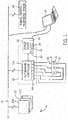
- FIG. 1 an embodiment of an industrial automation and control system 10 in accordance with aspects of the present disclosure is illustrated in FIG. 1 as including an automation component 12A, which here is an automation controller.
- the system 10 may include other automation components or controllers 12B, 12C, and 12D, which may or may not be disposed within the same or other enclosures, such as electrical cabinets.
- the enclosure 14 may house a variety of other electrical components, such as monitoring and/or control components, including relays, motor starters, and the like.
- the enclosure 14 may be suitable, for example, for assembly of a motor control center or use with industrial, commercial, marine, or other electrical systems.
- the enclosure 14 may be made of any suitable material, such as heavy gage sheet metal, reinforced plastics, and so forth, in order to protect the housed monitoring and/or control components from various risks, such as damage from fire, water, dust, tampering, and the like.
- the enclosure 14 may be any size suitable to satisfactorily house its contents.
- the enclosures 14 for industrial systems may be large.
- Such enclosures 14 may be temperature controlled in order to prevent the monitoring and/or control components from overheating.
- the enclosure 14 includes individual compartments or other structures that support the electrical components.
- automation controller 12A is disposed within enclosure 14 and adapted to interface with components of a machine process/system 16. It should be noted that such an interface may be facilitated by the use of certain network strategies. Indeed, an industry standard network may be employed to enable data transfer. Such networks permit the exchange of data in accordance with a predefined protocol, and may provide power for operation of networked elements.
- the process/system 16 may take many forms and include devices for accomplishing many different and varied purposes.
- the process/system 16 may comprise a compressor station, an oil refinery, a batch operation for making food items, a mechanized assembly line, and or any other process or system requiring automation.
- the process/system 16 may comprise a variety of operational components 18, such as electric motors, valves, actuators, temperature elements, pressure sensors, or a myriad of manufacturing, processing, material handling and other applications.
- the process/system 16 may comprise control and monitoring equipment for regulating process variables through automation and/or observation.
- the sensors 20 may comprise any number of devices adapted to provide information regarding process conditions.
- the actuators 22 may include any number of devices adapted to perform a mechanical action in response to a signal from a controller (e.g., the automation controller 12A).
- the sensors 20 and the actuators 22 may be utilized to operate process equipment. Indeed, they may be utilized within process loops that are monitored and controlled by the automation controller 12A. Such a process loop may be activated based on process inputs (e.g., input from a sensor 20) or direct operator input. Additionally, as indicated above, utilizing the actuators 22 and the sensors 20 may be accomplished through direct interaction with the automation controller 12A.
- these sensors 20 and actuators 22 are in communication with the automation controller 12A.
- the sensors 20 and actuators 22 may communicate with the automation controller 12A via one or more I/O modules 24 coupled to the automation controller 12A.
- the I/O modules 24 may transfer input and output signals between the automation controller 14 and the controlled process/system 16.
- the I/O modules 24 may be integrated with the automation controller 12A, or may be added or removed via expansion slots, bays or other suitable mechanism. For example, to add functionality to the automation controller 12A, additional I/O modules 24 may be added, such as if new sensors 20 or actuators 22 are added to control the process/system 16. These I/O modules serve as an electrical interface to the automation controller 12A and may be located proximate or remote from the controller including remote network interfaces to associated systems. The automation controller 12A may not require the I/O modules 24 to interact with the controlled and monitored process/system 16. In this situation, the connection between the automation controller 12A and the controlled and monitored process/system 16 may be direct, or it may still occur through the I/O modules 24.
- automation controller 12A is connected to a network 26.
- the automation controller 12A may communicate with and/or be controlled by a remote control/monitoring system 28 that is also connected to the network 26.
- the automation controller 12A may receive and activate process loops through the network 26 originating from the remote control/monitoring system 28.
- the I/O modules 24 may be located in close proximity to a portion of the control equipment, and away from the automation controller 12A. In such embodiments, data is communicated with remote modules over a common communication link, or the network 26, wherein modules on the network communicate via a standard communications protocol.
- Ethernet e.g., IEEE802.3, TCP/IP, UDP, EtherNet/IP, and so forth
- ControlNet e.g., ControlNet
- DeviceNet e.g., ControlNet
- Foundation Fieldbus (HI and Fast Ethernet) Modbus TCP, Profibus e.g., Ethernet, IEEE802.3, TCP/IP, UDP, EtherNet/IP, and so forth
- HI and Fast Ethernet Modbus
- Modbus TCP Profibus
- the system 10 also includes a display device 30, such as an array of LEDs or LCDs, or other addressable display locations configured to display input/output parameters, such as status of the system/process 16, operational components 18, the sensors 20, and/or the actuators 22.
- the display device 30 may include a processor 32, memory 34, and/or control circuitry 36.
- the memory 34 may be a tangible, non-transitory, computer-readable medium, and may include, for example, random-access memory, read-only memory, rewritable memory, hard drives, and the like.
- the memory 34 may be used to store programs, applications, or other instructions for the processor 32.
- the memory 34 may also store error codes, login history, access information, look up tables, and the like.
- the processor 32 may execute programs stored in memory 34 and may be used to display things on the display device, interpret user inputs, etc.
- the control circuitry 36 may include or be independent of the processor 32 and memory 34.
- the control circuitry 36 may control what is displayed on the display device, interpret inputs from the user, communicate with the automation controller, etc.
- the display device may include one or more input keys that enable a user to reprogram the automation controller 12A.
- the display device 30 may be connected to the automation controller 12A via a cable that is plugged into a communication interface port embedded in the automation controller 12A and the display device 30, respectively.
- the display device 30 may be installed in the enclosure 14 and include a port 38 (e.g., USB port) that is embedded in the display device 30.
- a user may connect a laptop computer 40, or some other tool to the display device 30 through port 38 in order to program the automation controller 12A, or perform other tasks, such as running diagnostics or troubleshooting.
- the laptop 40 may also be connected to the network 26 wirelessly, or through a wired connection.
- the port 38 may be installed in the display device's front panel so that it is accessible by a user when the enclosure 14 is closed. Further, the port 38 may specifically include a USB port. It should be noted that "USB" may be an industry standard that defines the cables, connectors, and communication protocols used in a bus for connection, communication, and power supply between computers and electronic devices. By utilizing the port 38, a user may connect a cable between a laptop 40 and the display device 30 in order to reprogram the automation controller 12A or upload an update to it without having to open the enclosure 14.
- FIG. 2 A prior art embodiment of display device 30 is shown in FIG. 2 .
- the prior art embodiment of display device 30 comprises multiple LEDs 42, each signifying an address, configured to indicate the status of inputs/outputs, processes/systems 16, operational components 18, sensors 20, and/or actuators 22, connected to the automation controller 12A.
- the LED 42 may display an amber color to indicate that the component is on and functioning.
- the LED 42 will remain off to indicate that the connected component is not on and functioning. It should be understood that these are merely examples.
- the addresses may be other colors and/or be configured to communicate other information.
- any suitable addressable display locations may be utilized, including LCDs, both LEDs and LCDs, conventional lights, and so forth.
- FIG. 3 An embodiment of display device 30 with an LED array configuration is shown in FIG. 3 .
- the LEDs 42 including inputs and outputs, are organized in two 3 x 5 arrays 44, 46, each signifying an address.
- This embodiment may also include a number of other LEDs 42 outside of the two 3 x 5 arrays 44, 46, used to convey information, such as the status of various components, to the user.
- the display device 30 may also include one or more input buttons 48, configured to allow the user to input commands. In a normal operating mode, each LED 42 or address communicates the status of a different input/output or component in the system.
- adjacent LEDs 42 or addresses are illuminated to display an amalgamated alphanumeric character that may be used to display a digit of an IP address, an error code, a command code, or some other number.
- the first 3 x 5 array 44 displays one amalgamated character
- the second 3 x 5 array 46 displays a second amalgamated character.
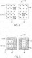
- FIG. 4 shows the two 3 x 5 arrays 44, 46 of display device 30 in normal operation mode.
- each LED 42 corresponds to an address and indicates the status of an input/output or connected component (e.g., process/system 16, operational components 18, sensors 20, actuators 22, etc.).
- input 08, output 04, and output 08 are on and running, so the corresponding LEDs 42 are illuminated, as indicated by the hatch pattern over each of those addresses. It should be understood that this is merely an example and normal run mode may involve illuminating any combination of the LEDs that correspond to the status of the various components.
- FIG. 5 shows the two 3 x 5 arrays 44, 46 of display device 30 in program mode.
- program mode a combination of adjacent LEDs 42 or addresses in the first 3 x 5 array 44 may be illuminated to show a first amalgamated alphanumeric character 50, in this case, a number three, and a combination of adjacent LEDs 42 or addresses in the second 3 x 5 array 46 may be illuminated to show a second amalgamated alphanumeric character 52, in this case, a number zero.
- the first and second amalgamated alphanumeric characters 50, 52 correspond to the last two digits of the final octet of the IP address from the automation controller 12A.
- the first and second amalgamated characters 50, 52 could be used to indicate other things, such as error codes, programs, routines, run time, etc.
- display device 30 may be capable of digit shifting so that display device 30 may be capable of displaying, or may allow a user to input/set numbers with more than two digits.
- LEDs 42 that illuminate a single color
- different colors of LEDs 42 or addresses may be used to signify different things (e.g., IP address, time, component status, errors, problems, etc.).
- FIG 6 is a flow chart illustrating exemplary logic 54 for setting the IP address of an automation controller 12A. It should be understood, however, that the present disclosure is not limited to setting an IP address and that a similar method may be used to input numbers for other purposes, such as command codes, etc.
- the user may press and hold the input button 42 until the LEDs 42 flash. This will move the automation controller 12A from normal operation mode to program mode.
- the particular component could be other than an automation controller, and the display could be used for setting or checking data other than network or IP addresses.
- buttons may comprise a location that can be touched or otherwise interfaced by a user, such as for closing or opening a membrane switch or other electrical contact device.
- the “button” could also comprise a “virtual button” of a touch display, or any other suitable input.
- the user may press and hold the input button 42 for three seconds in order to enter IP address add mode.
- the first 3 x 5 array 44 will then display a first amalgamated character 50 of zero.
- the user then presses the input button 48 to cycle through digits zero through nine. For example, the user would press input button 48 once to change the first amalgamated character 50 to the number one, and once more to change the first amalgamated character 50 to two. The user would continue this pattern until he or she reaches the desired number for the first amalgamated character 50.
- the user presses and holds the input button 48 for three seconds to set the first digit and move to the second digit.
- the second 3x5 array 46 will then display a second amalgamated character 52 of zero.
- the user presses the input button 48 to cycle through digits zero through nine. For example, the user would press input button 48 once to change the second amalgamated character 50 to the number one, and once more to change the second amalgamated character 50 to two. The user would continue this pattern until he or she reaches the desired number for the second amalgamated character 52.
- the user presses and holds the input button 48 for three seconds to set the digit for the second amalgamated character 52.
- the user has input both of the last two digits of the final octet of the desired IP address. It should be understood, however, that in some embodiments the user may be able to enter more than two digits. For example, the user may be able to enter an entire IP address. Furthermore, the user may use a similar method to input command codes, or other codes of two or more digits.
- the user presses and holds the input button 48 for three seconds to exit IP address add mode and return to normal operating mode.
- control circuitry configured to control a display device.
- the display device illuminates one or more individual addresses in an array of addresses, wherein each of the individual addresses communicates information to a user.
- the display device illuminates two or more adjacent addresses in the array of addresses in order to display a first amalgamated alphanumeric character.
- the user may program (or check) two alphanumeric characters that are amalgamated by addressing adjacent regions of the display under the control of the control circuitry discussed above.
- a single such character may be formed, or more than two may be available.
- similar techniques may be used for indicating only the number of amalgamated characters provided, or the user may be able to "scroll through" any number of numbers and/or letters (or other characters) that can be formed and displayed as amalgamated characters (such as for setting longer addresses, programming parameters, settings, and so forth).
Landscapes
- Engineering & Computer Science (AREA)
- Physics & Mathematics (AREA)
- General Physics & Mathematics (AREA)
- Theoretical Computer Science (AREA)
- Computer Hardware Design (AREA)
- General Engineering & Computer Science (AREA)
- Automation & Control Theory (AREA)
- Human Computer Interaction (AREA)
- Programmable Controllers (AREA)
- Control Of Indicators Other Than Cathode Ray Tubes (AREA)
Description
- The present disclosure relates generally to automation devices, such as controllers, and, more particularly, to a systems and methods for displaying amalgamated characters using an array of addresses on the display of an automation device.
- Automation devices, such as programmable automation controllers, are often utilized in industrial systems to control and make operational decisions for the systems with which the automation devices are connected. For example, such automation controllers are typically made up of several components, examples of which may include a processor, memory, input/output assemblies, a power supply, or a display. To communicate with the other automation components in the system, the internet protocol (IP) or other network address of the automation controller must be set by a user. Typically, setting the network address requires connecting the automation device to a laptop or other tool, such as a smart device or human interface module (HIM), and the like. It would be beneficial to have a way to set the IP address of an automation device without having to connect a laptop or other tool.
-
US 2009/276096 A1 relates to a device and a method for controlling a display which makes use of a virtual display buffer that acts as an intermediary between data input and display output. The data stored in the virtual display buffer is in a generic, readable first format. A display software driver translates the data stored in the virtual display buffer to a second format usable by a hardware display driver to control a specific display device. -
DE 297 12 772 U1 relates to a display device for a stove. -
US 2008/225039 A1 relates to a display control apparatus which improves the visibility of a display unit (for example, wristwatch) having a normal display section and a normal non-display section provided outside the normal display section along its at least one side. When it is not sensed that the display unit is inclined at a predetermined angle to a horizontal surface, time information is displayed in a normal size on the normal display section. When it is sensed that the display unit is inclined at the predetermined angle to the horizontal surface, the time information is displayed in an enlarged size on a whole of the normal display and non-display sections for a predetermined time. - It is therefore the object of the present invention to provide an improved display of an automation component for displaying alphanumeric characters, as well as a corresponding method.
- This object is solved by the subject matter of the independent claims.
- Preferred embodiments are defined by the dependent claims.
- Certain embodiments commensurate of the presently contemplated technologies are summarized below. These embodiments are not intended to limit the scope of the claimed invention, but rather these embodiments are intended only to provide a brief summary of possible forms of the technologies. Indeed, the disclosure may encompass a variety of forms that may be similar to or different from the embodiments set forth below.
- In a first embodiment, an automation component includes a display having addressable locations in an array for display of data, and control circuitry that is configured to control the display. In a first mode, the control circuitry controls illumination of one or more individual locations of the display in the array for conveying individual data corresponding to the individual locations. In a second mode, the control circuitry controls illumination of two or more individual locations in the array to display an amalgamated alphanumeric character.
- In a second embodiment, an automation component includes an automation controller, a display device communicatively coupled to the automation controller and having addressable locations in an array for display of data, and control circuitry. The control circuitry is configured to control the display. In a first mode, the control circuitry controls illumination of one or more individual locations of the display in the array for conveying individual data corresponding to the individual locations and indicative of status of a corresponding input, output, or automation component in communication with the automation controller. In a second mode, the control circuitry controls illumination of two or more individual locations in the array to display an amalgamated alphanumeric character.
- In a third embodiment, a method of controlling an automation component includes illuminating one or more individual locations, in a normal operation mode, such that the one or more individual locations convey individual data corresponding to the individual locations, selecting, via a user interface, a program mode, selecting, via the user interface, an input mode, illuminating two or more individual locations to display an amalgamated alphanumeric character, selecting, via the user interface, one or more numbers that correspond to the amalgamated alphanumeric character, exiting, via the user interface, the input mode.
- These and other features, aspects, and advantages of the present invention will become better understood when the following detailed description is read with reference to the accompanying drawings in which like characters represent like parts throughout the drawings, wherein:
-
FIG. 1 is a schematic of an exemplary embodiment of an industrial automation and control system in accordance with aspects of the present disclosure; -
FIG. 2 is a schematic of a prior art embodiment of the display device, as may appear in an industrial automation and control system in accordance with aspects of the present disclosure; -
FIG. 3 is a schematic of an embodiment of the display device, as may appear in an industrial automation and control system shown inFIG. 1 in accordance with aspects of the present disclosure; -
FIG. 4 shows an exemplary embodiment of the display device shown inFIG. 3 having first and second 3 x 5 arrays of addresses in accordance with aspects of the present disclosure; -
FIG. 5 shows an exemplary embodiment of the display device shown inFIGS. 3 and4 using first and second 3 x 5 arrays of addresses to display first and second amalgamated characters in accordance with aspects of the present disclosure; and -
FIG. 6 is a flowchart illustrating a process for setting a network address of an automation component, as may appear in industrial automation and control system shown inFIG. 1 , in accordance with aspects of the present disclosure. - One or more specific embodiments of the present invention will be described below. In an effort to provide a concise description of these embodiments, all features of an actual implementation may not be described in the specification. It should be appreciated that in the development of any such actual implementation, as in any engineering or design project, numerous implementation-specific decisions must be made to achieve the developers' specific goals, such as compliance with system-related and business-related constraints, which may vary from one implementation to another. Moreover, it should be appreciated that such a development effort might be complex and time consuming, but would nevertheless be a routine undertaking of design, fabrication, and manufacture for those of ordinary skill having the benefit of this disclosure.
- When introducing elements of various embodiments of the present invention, the articles "a," "an," "the," and "said" are intended to mean that there are one or more of the elements. The terms "comprising," "including," and "having" are intended to be inclusive and mean that there may be additional elements other than the listed elements.
- Setting the network address of an automation component typically requires connecting a laptop, smart device, HIM, or other tool to the automation component. It would be beneficial to give the user the capability of setting the network address of an automation component without the use of extra equipment. However, modifying the display device of an automation component to mimic the features of a laptop or other similar tool (i.e., LCD screen, keypad or touchscreen, user interface, etc.) could significantly increase the cost of the display device. Accordingly, it would be desirable to have an automation component display device that allows the user to set the network address of the automation device, but is not substantially more expensive than currently available display devices.
- It should be noted that certain references are made in the following discussion to setting an address, typically a network address of an automation device. The present techniques, however, are not limited to such applications, but may be used any time a more limited, addressable display is repurposed from indication data, such as status data in an array to the use of "amalgamated" characters by appropriate addressing of the character locations. The term "amalgamated" here may refer to a composite character that is made up of locations, typically adjacent locations that are addressed (typically made light or dark), but that otherwise serve other functions, such as for status indication. Further, while reference is made below to IP addresses, any network address may be programmed (or checked) in the ways disclosed. Moreover, while the primary example given in the disclosure is that of an automation controller, in practice the technique is not so limited, but may be used on any automation component that has a display that can be repurposed for display of amalgamated characters as disclosed.
- As discussed in detail below, embodiments of the present techniques function to provide a display device for an automation controller with an array of addresses capable of showing the status of inputs, outputs, and/or various connected components in one mode of operation and then illuminating multiple adjacent addresses to display amalgamated alpha-numeric characters in a second mode of operation. The display device may be located locally or remotely from the system in which the automation controller resides. For example, the automation controller may be housed in an enclosure and the display device may be installed in the enclosure's door so that the display device is accessible when the enclosure's door is shut. As another example, the display device may be a stand-alone device that is connected to the automation controller via a cable. The display device may also be a "dumb" device (at least with respect to certain functional aspects) that lacks electronic processing power of its own for performing at least certain tasks and relies on processing from the automation controller to perform such tasks. The display device may include one or more communication interface ports for connection to a personal computer (PC) or other electronic device. It should be noted that the communication interface port may be any protocol capable of communicating with electronic devices but, for purposes of the present discussion, universal serial bus (USB) port will be used as an embodiment of the communication interface port.
- With the foregoing in mind, an embodiment of an industrial automation and
control system 10 in accordance with aspects of the present disclosure is illustrated inFIG. 1 as including anautomation component 12A, which here is an automation controller. Thesystem 10 may include other automation components orcontrollers enclosure 14 may house a variety of other electrical components, such as monitoring and/or control components, including relays, motor starters, and the like. - The
enclosure 14 may be suitable, for example, for assembly of a motor control center or use with industrial, commercial, marine, or other electrical systems. Theenclosure 14 may be made of any suitable material, such as heavy gage sheet metal, reinforced plastics, and so forth, in order to protect the housed monitoring and/or control components from various risks, such as damage from fire, water, dust, tampering, and the like. Generally, theenclosure 14 may be any size suitable to satisfactorily house its contents. Thus, theenclosures 14 for industrial systems may be large.Such enclosures 14 may be temperature controlled in order to prevent the monitoring and/or control components from overheating. In certain embodiments, theenclosure 14 includes individual compartments or other structures that support the electrical components. - In the illustrated embodiment,
automation controller 12A is disposed withinenclosure 14 and adapted to interface with components of a machine process/system 16. It should be noted that such an interface may be facilitated by the use of certain network strategies. Indeed, an industry standard network may be employed to enable data transfer. Such networks permit the exchange of data in accordance with a predefined protocol, and may provide power for operation of networked elements. - The process/
system 16 may take many forms and include devices for accomplishing many different and varied purposes. For example, the process/system 16 may comprise a compressor station, an oil refinery, a batch operation for making food items, a mechanized assembly line, and or any other process or system requiring automation. Accordingly, the process/system 16 may comprise a variety ofoperational components 18, such as electric motors, valves, actuators, temperature elements, pressure sensors, or a myriad of manufacturing, processing, material handling and other applications. - Further, the process/
system 16 may comprise control and monitoring equipment for regulating process variables through automation and/or observation. Thesensors 20 may comprise any number of devices adapted to provide information regarding process conditions. Theactuators 22 may include any number of devices adapted to perform a mechanical action in response to a signal from a controller (e.g., theautomation controller 12A). Thesensors 20 and theactuators 22 may be utilized to operate process equipment. Indeed, they may be utilized within process loops that are monitored and controlled by theautomation controller 12A. Such a process loop may be activated based on process inputs (e.g., input from a sensor 20) or direct operator input. Additionally, as indicated above, utilizing theactuators 22 and thesensors 20 may be accomplished through direct interaction with theautomation controller 12A. - As illustrated, these
sensors 20 andactuators 22 are in communication with theautomation controller 12A. In one embodiment, thesensors 20 andactuators 22 may communicate with theautomation controller 12A via one or more I/O modules 24 coupled to theautomation controller 12A. The I/O modules 24 may transfer input and output signals between theautomation controller 14 and the controlled process/system 16. - The I/
O modules 24 may be integrated with theautomation controller 12A, or may be added or removed via expansion slots, bays or other suitable mechanism. For example, to add functionality to theautomation controller 12A, additional I/O modules 24 may be added, such as ifnew sensors 20 oractuators 22 are added to control the process/system 16. These I/O modules serve as an electrical interface to theautomation controller 12A and may be located proximate or remote from the controller including remote network interfaces to associated systems. Theautomation controller 12A may not require the I/O modules 24 to interact with the controlled and monitored process/system 16. In this situation, the connection between theautomation controller 12A and the controlled and monitored process/system 16 may be direct, or it may still occur through the I/O modules 24. - In some embodiments,
automation controller 12A is connected to anetwork 26. Theautomation controller 12A may communicate with and/or be controlled by a remote control/monitoring system 28 that is also connected to thenetwork 26. Theautomation controller 12A may receive and activate process loops through thenetwork 26 originating from the remote control/monitoring system 28. In some embodiments, the I/O modules 24 may be located in close proximity to a portion of the control equipment, and away from theautomation controller 12A. In such embodiments, data is communicated with remote modules over a common communication link, or thenetwork 26, wherein modules on the network communicate via a standard communications protocol. Many industrial controllers can communicate via network technologies such as Ethernet (e.g., IEEE802.3, TCP/IP, UDP, EtherNet/IP, and so forth), ControlNet, DeviceNet. or other network protocols (Foundation Fieldbus (HI and Fast Ethernet) Modbus TCP, Profibus) and also communicate to higher level computing systems. - In the illustrated embodiment, the
system 10 also includes adisplay device 30, such as an array of LEDs or LCDs, or other addressable display locations configured to display input/output parameters, such as status of the system/process 16,operational components 18, thesensors 20, and/or theactuators 22. In some embodiments, thedisplay device 30 may include aprocessor 32,memory 34, and/orcontrol circuitry 36. Thememory 34 may be a tangible, non-transitory, computer-readable medium, and may include, for example, random-access memory, read-only memory, rewritable memory, hard drives, and the like. Thememory 34 may be used to store programs, applications, or other instructions for theprocessor 32. Thememory 34 may also store error codes, login history, access information, look up tables, and the like. Theprocessor 32 may execute programs stored inmemory 34 and may be used to display things on the display device, interpret user inputs, etc. Thecontrol circuitry 36 may include or be independent of theprocessor 32 andmemory 34. Thecontrol circuitry 36 may control what is displayed on the display device, interpret inputs from the user, communicate with the automation controller, etc. The display device may include one or more input keys that enable a user to reprogram theautomation controller 12A. Thedisplay device 30 may be connected to theautomation controller 12A via a cable that is plugged into a communication interface port embedded in theautomation controller 12A and thedisplay device 30, respectively. In certain embodiments, thedisplay device 30 may be installed in theenclosure 14 and include a port 38 (e.g., USB port) that is embedded in thedisplay device 30. A user may connect alaptop computer 40, or some other tool to thedisplay device 30 throughport 38 in order to program theautomation controller 12A, or perform other tasks, such as running diagnostics or troubleshooting. Thelaptop 40 may also be connected to thenetwork 26 wirelessly, or through a wired connection. - The
port 38 may be installed in the display device's front panel so that it is accessible by a user when theenclosure 14 is closed. Further, theport 38 may specifically include a USB port. It should be noted that "USB" may be an industry standard that defines the cables, connectors, and communication protocols used in a bus for connection, communication, and power supply between computers and electronic devices. By utilizing theport 38, a user may connect a cable between alaptop 40 and thedisplay device 30 in order to reprogram theautomation controller 12A or upload an update to it without having to open theenclosure 14. - A prior art embodiment of
display device 30 is shown inFIG. 2 . The prior art embodiment ofdisplay device 30 comprisesmultiple LEDs 42, each signifying an address, configured to indicate the status of inputs/outputs, processes/systems 16,operational components 18,sensors 20, and/oractuators 22, connected to theautomation controller 12A. TheLED 42 may display an amber color to indicate that the component is on and functioning. TheLED 42 will remain off to indicate that the connected component is not on and functioning. It should be understood that these are merely examples. In other embodiments the addresses may be other colors and/or be configured to communicate other information. Here again, it should be noted that, while LEDs are referred to here, any suitable addressable display locations may be utilized, including LCDs, both LEDs and LCDs, conventional lights, and so forth. - An embodiment of
display device 30 with an LED array configuration is shown inFIG. 3 . In the illustrated configuration, theLEDs 42, including inputs and outputs, are organized in two 3 x 5arrays other LEDs 42 outside of the two 3 x 5arrays display device 30 may also include one ormore input buttons 48, configured to allow the user to input commands. In a normal operating mode, eachLED 42 or address communicates the status of a different input/output or component in the system. In program mode,adjacent LEDs 42 or addresses are illuminated to display an amalgamated alphanumeric character that may be used to display a digit of an IP address, an error code, a command code, or some other number. In the present embodiment, the first 3 x 5array 44 displays one amalgamated character, while the second 3 x 5array 46 displays a second amalgamated character. -
FIG. 4 shows the two 3 x 5arrays display device 30 in normal operation mode. In normal operation mode, eachLED 42 corresponds to an address and indicates the status of an input/output or connected component (e.g., process/system 16,operational components 18,sensors 20,actuators 22, etc.). In the example shown inFIG. 4 ,input 08,output 04, andoutput 08 are on and running, so the correspondingLEDs 42 are illuminated, as indicated by the hatch pattern over each of those addresses. It should be understood that this is merely an example and normal run mode may involve illuminating any combination of the LEDs that correspond to the status of the various components. -
FIG. 5 shows the two 3 x 5arrays display device 30 in program mode. In program mode, a combination ofadjacent LEDs 42 or addresses in the first 3 x 5array 44 may be illuminated to show a first amalgamatedalphanumeric character 50, in this case, a number three, and a combination ofadjacent LEDs 42 or addresses in the second 3 x 5array 46 may be illuminated to show a second amalgamatedalphanumeric character 52, in this case, a number zero. In the present embodiment, the first and second amalgamatedalphanumeric characters automation controller 12A. However, in other embodiments, the first and secondamalgamated characters display device 30 may be capable of digit shifting so thatdisplay device 30 may be capable of displaying, or may allow a user to input/set numbers with more than two digits. Furthermore, while the present embodiments includeLEDs 42 that illuminate a single color, it should be understood that different colors ofLEDs 42 or addresses may be used to signify different things (e.g., IP address, time, component status, errors, problems, etc.). -
FIG 6 . is a flow chart illustratingexemplary logic 54 for setting the IP address of anautomation controller 12A. It should be understood, however, that the present disclosure is not limited to setting an IP address and that a similar method may be used to input numbers for other purposes, such as command codes, etc. Atblock 56, the user may press and hold theinput button 42 until theLEDs 42 flash. This will move theautomation controller 12A from normal operation mode to program mode. Here again, it should be borne in mind that the particular component could be other than an automation controller, and the display could be used for setting or checking data other than network or IP addresses. Still further, it should be noted that while a "button" is referenced here, in practice, the "button" may comprise a location that can be touched or otherwise interfaced by a user, such as for closing or opening a membrane switch or other electrical contact device. The "button" could also comprise a "virtual button" of a touch display, or any other suitable input. - As illustrated at
block 58, the user may press and hold theinput button 42 for three seconds in order to enter IP address add mode. The first 3 x 5array 44 will then display a firstamalgamated character 50 of zero. - At
block 60 the user then presses theinput button 48 to cycle through digits zero through nine. For example, the user would pressinput button 48 once to change the firstamalgamated character 50 to the number one, and once more to change the firstamalgamated character 50 to two. The user would continue this pattern until he or she reaches the desired number for the firstamalgamated character 50. - At
block 62 the user presses and holds theinput button 48 for three seconds to set the first digit and move to the second digit. Thesecond 3x5 array 46 will then display a secondamalgamated character 52 of zero. - At
block 64 the user presses theinput button 48 to cycle through digits zero through nine. For example, the user would pressinput button 48 once to change the secondamalgamated character 50 to the number one, and once more to change the secondamalgamated character 50 to two. The user would continue this pattern until he or she reaches the desired number for the secondamalgamated character 52. - At
block 66 the user presses and holds theinput button 48 for three seconds to set the digit for the secondamalgamated character 52. At this point, the user has input both of the last two digits of the final octet of the desired IP address. It should be understood, however, that in some embodiments the user may be able to enter more than two digits. For example, the user may be able to enter an entire IP address. Furthermore, the user may use a similar method to input command codes, or other codes of two or more digits. Once all digits are set, inblock 68, the user presses and holds theinput button 48 for three seconds to exit IP address add mode and return to normal operating mode. - Technical effects of the invention include control circuitry configured to control a display device. In a first mode, the display device illuminates one or more individual addresses in an array of addresses, wherein each of the individual addresses communicates information to a user. In a second mode, the display device illuminates two or more adjacent addresses in the array of addresses in order to display a first amalgamated alphanumeric character.
- In this example, the user may program (or check) two alphanumeric characters that are amalgamated by addressing adjacent regions of the display under the control of the control circuitry discussed above. In other embodiments, a single such character may be formed, or more than two may be available. Moreover, similar techniques may be used for indicating only the number of amalgamated characters provided, or the user may be able to "scroll through" any number of numbers and/or letters (or other characters) that can be formed and displayed as amalgamated characters (such as for setting longer addresses, programming parameters, settings, and so forth).
- This written description uses examples to disclose the invention, including the best mode, and also to enable any person skilled in the art to practice the invention, including making and using any devices or systems and performing any incorporated methods. The patentable scope of the invention is defined by the claims, and may include other examples that occur to those skilled in the art. Such other examples are intended to be within the scope of the claims if they have structural elements that do not differ from the literal language of the claims, or if they include equivalent structural elements with insubstantial differences from the literal language of the claims.
- While only certain features of the invention have been illustrated and described herein, many modifications and changes will occur to those skilled in the art. It is, therefore, to be understood that the appended claims are intended to cover all such modifications and changes as fall within the scope of the invention.
Claims (15)
- An automation component comprising:a display (30) having addressable locations (42) in an array (44, 46) for display of data, the display including control circuitry (36) configured to control the display,wherein, in a first mode, the control circuitry is configured to control illumination of each of said individual locations of the display in the array for conveying, by each of said individual locations, the status of a different input, output or component in a control system, andwherein in a second mode, the control circuitry is configured to control illumination of said individual locations such that a plurality of individual adjacent locations in the array displays an amalgamated alphanumeric character (50, 52).
- The automation component of claim 1, wherein the control circuitry is configured to receive inputs from a user via one or more input buttons (48).
- The automation component of claim 1 or 2, wherein the automation component comprises an automation controller (12A).
- The automation component of claim 1, further comprising an automation controller (12A), wherein the display is communicatively coupled to the automation controller, and wherein the input, output, or component is in communication with the automation controller.
- The automation component of claim 4, the display further comprising one or more input buttons (48).
- The automation component of claim 4 or 5, wherein the automation controller is disposed within an enclosure (14).
- The automation component of claim 6, wherein the display device is disposed on the exterior of the enclosure.
- The industrial automation system of one of claims 1 to 7, wherein the locations comprise LEDs.
- The automation component of one of claims 1 to 8, wherein the array of locations comprises a first and a second 3 x 5 array of locations.
- The automation component of claim 9, wherein a first combination of locations in the first 3 x 5 array of locations is addressable to display the amalgamated alphanumeric character, and wherein a second combination of locations in the second 3 x 5 array of locations is addressable to display a second amalgamated alphanumeric character.
- The automation component of one of claims 1 to 10, wherein the amalgamated alphanumeric character corresponds to an error code.
- The automation component of one of claims 1 to 10, wherein the amalgamated alphanumeric character corresponds to a network address.
- A method of controlling an automation component comprising:controlling, in a first mode, illumination of each of a plurality of individual locations (42) in an array (44, 46) of a display (30) for conveying, by each of said individual locations, the status of a different input, output or component in a control system; andcontrolling, in a second mode, illumination of said individual locations such that a plurality of individual adjacent locations in the array displays an amalgamated alphanumeric character (50, 52).
- The method of claim 13, wherein the automation component enters the second mode in response to a user input received via a user interface, the method further comprising:selecting, via the user interface, one or more numbers that correspond to the amalgamated alphanumeric character, comprising:pressing (60) a button (48) one or more times to cycle through the displayed amalgamated alphanumeric character until a desired first digit is reached;pressing and holding (62) the button for a set period of time to set the first digit;pressing (64) the button one or more times to cycle through digits until a desired second digit is reached; andpressing and holding (66) the button for the set period of time to set the second digit; andreceiving a user input, via the user interface, instructing the automation component to exit the second mode.
- The method of claim 13 or 14 wherein the amalgamated alphanumeric character corresponds to a network address.
Applications Claiming Priority (1)
| Application Number | Priority Date | Filing Date | Title |
|---|---|---|---|
| US14/631,269 US10467988B2 (en) | 2015-02-25 | 2015-02-25 | Amalgamated alphanumeric character display system and method |
Publications (2)
| Publication Number | Publication Date |
|---|---|
| EP3062304A1 EP3062304A1 (en) | 2016-08-31 |
| EP3062304B1 true EP3062304B1 (en) | 2017-12-13 |
Family
ID=55521452
Family Applications (1)
| Application Number | Title | Priority Date | Filing Date |
|---|---|---|---|
| EP16157074.2A Active EP3062304B1 (en) | 2015-02-25 | 2016-02-24 | Amalgamated alphanumeric character display system and method |
Country Status (3)
| Country | Link |
|---|---|
| US (1) | US10467988B2 (en) |
| EP (1) | EP3062304B1 (en) |
| CN (1) | CN105911886B (en) |
Families Citing this family (3)
| Publication number | Priority date | Publication date | Assignee | Title |
|---|---|---|---|---|
| CN109313479B (en) * | 2016-05-25 | 2022-03-29 | 蒂尼电源株式会社 | Communication transmitter/receiver capable of inputting unique identification ID for communication by counting method |
| KR102045618B1 (en) * | 2016-05-25 | 2019-11-18 | 최창준 | Communication Apparatus with ID input method which is appropriate to numeral system |
| US10375020B2 (en) * | 2017-01-18 | 2019-08-06 | Cisco Technology, Inc. | Security policy for HTTPS using DNS |
Family Cites Families (16)
| Publication number | Priority date | Publication date | Assignee | Title |
|---|---|---|---|---|
| US4462026A (en) * | 1981-12-17 | 1984-07-24 | Westinghouse Electric Corp. | Electronic display apparatus using time multiplexed data and control signals |
| US6150996A (en) * | 1998-08-26 | 2000-11-21 | Addco, Inc. | Changeable message sign system with reconfigurable sign screen |
| DE29712772U1 (en) | 1996-07-31 | 1997-09-25 | Siemens AG, 80333 München | Display device for a stove |
| US6100858A (en) * | 1997-09-30 | 2000-08-08 | Infineon Technologies North America Corp. | Alphanumeric display with 21-dot matrix format |
| US7312773B1 (en) * | 1999-07-09 | 2007-12-25 | Rapid Prototypes, Inc. | Illuminated wearable ornament |
| JP5087959B2 (en) | 2007-03-15 | 2012-12-05 | カシオ計算機株式会社 | Display control device, electronic wristwatch, and display control program |
| US20090276096A1 (en) | 2008-05-02 | 2009-11-05 | Carrier Corporation | Device and method for controlling a display using a virtual display buffer |
| GB0904100D0 (en) * | 2009-03-10 | 2009-04-22 | Bradford Pharma Ltd | Use of rosuvastatin lactols as medicaments |
| US8810359B2 (en) * | 2010-06-23 | 2014-08-19 | Lumenpulse Lighting, Inc. | Assembling and controlling light unit arrays |
| US8579639B2 (en) * | 2010-08-20 | 2013-11-12 | Rockwell Automation Technologies, Inc. | Systems and methods for coupling input/output devices |
| US9055687B2 (en) * | 2010-08-20 | 2015-06-09 | Rockwell Automation Technologies, Inc. | Input/output circuits and devices having physically corresponding status indicators |
| CN202145267U (en) | 2011-03-22 | 2012-02-15 | 中国林业科学研究院林业研究所 | Multi-channel universal ecology data collector |
| CN102419559B (en) | 2011-11-15 | 2013-10-23 | 北京千驷驭电气有限公司 | Train traction control system |
| CN103019125B (en) | 2012-12-29 | 2014-12-31 | 国电南京自动化股份有限公司 | Multitask real-time data processing system and data recording and data analyzing method |
| US9141211B2 (en) * | 2013-01-09 | 2015-09-22 | Lenovo (Singapore) Pte. Ltd. | Touchpad operational mode |
| US10706770B2 (en) * | 2014-07-16 | 2020-07-07 | Ultravision Technologies, Llc | Display system having module display panel with circuitry for bidirectional communication |
-
2015
- 2015-02-25 US US14/631,269 patent/US10467988B2/en active Active
-
2016
- 2016-02-24 EP EP16157074.2A patent/EP3062304B1/en active Active
- 2016-02-24 CN CN201610101444.3A patent/CN105911886B/en active Active
Non-Patent Citations (1)
| Title |
|---|
| None * |
Also Published As
| Publication number | Publication date |
|---|---|
| US20160247486A1 (en) | 2016-08-25 |
| US10467988B2 (en) | 2019-11-05 |
| CN105911886B (en) | 2018-11-20 |
| EP3062304A1 (en) | 2016-08-31 |
| CN105911886A (en) | 2016-08-31 |
Similar Documents
| Publication | Publication Date | Title |
|---|---|---|
| US10969759B2 (en) | Safety controller module | |
| EP3201704B1 (en) | Safety and programmable logic integration system | |
| US9880539B2 (en) | Programmable control module for an industrial device | |
| US20100082869A1 (en) | Stackable i/o modules appearing as standard usb mass storage devices | |
| US20060095855A1 (en) | HMI reconfiguration method and system | |
| US20120109343A1 (en) | Display module for toolless coupling with programmable controller | |
| US20170052524A1 (en) | Apparatus and method for universal setup, monitoring and control of field devices for a plant | |
| EP2615896B1 (en) | System and method for coupling an automation controller and scaleable module | |
| US10467988B2 (en) | Amalgamated alphanumeric character display system and method | |
| EP1435552B1 (en) | A field device for a fieldbus system | |
| EP2876515B1 (en) | System and method for an input-driven, switching-enabled, display device for an automation controller | |
| JP6163735B2 (en) | SAFE SLAVE UNIT, ITS CONTROL METHOD, CONTROL PROGRAM, AND SAFETY CONTROL SYSTEM | |
| Mahapatra et al. | PLC-Based Home Automation System | |
| US9779902B2 (en) | Configurable modular intelligent electronic overload device and system with embedded programming tool | |
| Gowda et al. | Design and Implementation of HMI by Enhancing Display and Data Logging Capabilities for Improved Process Control | |
| Harwell | Integrated HMI and PLC | |
| Pinnekamp | Product automation | |
| US9135395B2 (en) | Element specific variable translation | |
| KR20100013005A (en) | Factory automation system that using ethernet | |
| KR200372360Y1 (en) | microprocessor push button lamp switch | |
| Dumitru et al. | Process Control Simulator using programmable controller technology | |
| Baudin | Performing operations on machines | |
| Thaher | Practical PLC Applications | |
| KR20210052113A (en) | MR-Smart Manufacturing Training System for Smart Manufacturing Convergence Technology Training Combined with Automation PLC Technology and IOT Technology | |
| Kaftan | PLC Basic Course With SIMATIC S7 |
Legal Events
| Date | Code | Title | Description |
|---|---|---|---|
| PUAI | Public reference made under article 153(3) epc to a published international application that has entered the european phase |
Free format text: ORIGINAL CODE: 0009012 |
|
| AK | Designated contracting states |
Kind code of ref document: A1 Designated state(s): AL AT BE BG CH CY CZ DE DK EE ES FI FR GB GR HR HU IE IS IT LI LT LU LV MC MK MT NL NO PL PT RO RS SE SI SK SM TR |
|
| AX | Request for extension of the european patent |
Extension state: BA ME |
|
| 17P | Request for examination filed |
Effective date: 20170118 |
|
| RBV | Designated contracting states (corrected) |
Designated state(s): AL AT BE BG CH CY CZ DE DK EE ES FI FR GB GR HR HU IE IS IT LI LT LU LV MC MK MT NL NO PL PT RO RS SE SI SK SM TR |
|
| 17Q | First examination report despatched |
Effective date: 20170307 |
|
| GRAP | Despatch of communication of intention to grant a patent |
Free format text: ORIGINAL CODE: EPIDOSNIGR1 |
|
| INTG | Intention to grant announced |
Effective date: 20170727 |
|
| GRAS | Grant fee paid |
Free format text: ORIGINAL CODE: EPIDOSNIGR3 |
|
| GRAA | (expected) grant |
Free format text: ORIGINAL CODE: 0009210 |
|
| REG | Reference to a national code |
Ref country code: GB Ref legal event code: FG4D |
|
| REG | Reference to a national code |
Ref country code: AT Ref legal event code: REF Ref document number: 955091 Country of ref document: AT Kind code of ref document: T Effective date: 20171215 Ref country code: CH Ref legal event code: EP |
|
| REG | Reference to a national code |
Ref country code: IE Ref legal event code: FG4D |
|
| REG | Reference to a national code |
Ref country code: DE Ref legal event code: R096 Ref document number: 602016001040 Country of ref document: DE |
|
| REG | Reference to a national code |
Ref country code: FR Ref legal event code: PLFP Year of fee payment: 3 |
|
| REG | Reference to a national code |
Ref country code: NL Ref legal event code: MP Effective date: 20171213 |
|
| PG25 | Lapsed in a contracting state [announced via postgrant information from national office to epo] |
Ref country code: FI Free format text: LAPSE BECAUSE OF FAILURE TO SUBMIT A TRANSLATION OF THE DESCRIPTION OR TO PAY THE FEE WITHIN THE PRESCRIBED TIME-LIMIT Effective date: 20171213 Ref country code: NO Free format text: LAPSE BECAUSE OF FAILURE TO SUBMIT A TRANSLATION OF THE DESCRIPTION OR TO PAY THE FEE WITHIN THE PRESCRIBED TIME-LIMIT Effective date: 20180313 Ref country code: SE Free format text: LAPSE BECAUSE OF FAILURE TO SUBMIT A TRANSLATION OF THE DESCRIPTION OR TO PAY THE FEE WITHIN THE PRESCRIBED TIME-LIMIT Effective date: 20171213 |
|
| REG | Reference to a national code |
Ref country code: AT Ref legal event code: MK05 Ref document number: 955091 Country of ref document: AT Kind code of ref document: T Effective date: 20171213 |
|
| PG25 | Lapsed in a contracting state [announced via postgrant information from national office to epo] |
Ref country code: BG Free format text: LAPSE BECAUSE OF FAILURE TO SUBMIT A TRANSLATION OF THE DESCRIPTION OR TO PAY THE FEE WITHIN THE PRESCRIBED TIME-LIMIT Effective date: 20180313 Ref country code: LV Free format text: LAPSE BECAUSE OF FAILURE TO SUBMIT A TRANSLATION OF THE DESCRIPTION OR TO PAY THE FEE WITHIN THE PRESCRIBED TIME-LIMIT Effective date: 20171213 Ref country code: HR Free format text: LAPSE BECAUSE OF FAILURE TO SUBMIT A TRANSLATION OF THE DESCRIPTION OR TO PAY THE FEE WITHIN THE PRESCRIBED TIME-LIMIT Effective date: 20171213 Ref country code: RS Free format text: LAPSE BECAUSE OF FAILURE TO SUBMIT A TRANSLATION OF THE DESCRIPTION OR TO PAY THE FEE WITHIN THE PRESCRIBED TIME-LIMIT Effective date: 20171213 Ref country code: GR Free format text: LAPSE BECAUSE OF FAILURE TO SUBMIT A TRANSLATION OF THE DESCRIPTION OR TO PAY THE FEE WITHIN THE PRESCRIBED TIME-LIMIT Effective date: 20180314 |
|
| PG25 | Lapsed in a contracting state [announced via postgrant information from national office to epo] |
Ref country code: NL Free format text: LAPSE BECAUSE OF FAILURE TO SUBMIT A TRANSLATION OF THE DESCRIPTION OR TO PAY THE FEE WITHIN THE PRESCRIBED TIME-LIMIT Effective date: 20171213 |
|
| PG25 | Lapsed in a contracting state [announced via postgrant information from national office to epo] |
Ref country code: CZ Free format text: LAPSE BECAUSE OF FAILURE TO SUBMIT A TRANSLATION OF THE DESCRIPTION OR TO PAY THE FEE WITHIN THE PRESCRIBED TIME-LIMIT Effective date: 20171213 Ref country code: ES Free format text: LAPSE BECAUSE OF FAILURE TO SUBMIT A TRANSLATION OF THE DESCRIPTION OR TO PAY THE FEE WITHIN THE PRESCRIBED TIME-LIMIT Effective date: 20171213 Ref country code: CY Free format text: LAPSE BECAUSE OF FAILURE TO SUBMIT A TRANSLATION OF THE DESCRIPTION OR TO PAY THE FEE WITHIN THE PRESCRIBED TIME-LIMIT Effective date: 20171213 Ref country code: EE Free format text: LAPSE BECAUSE OF FAILURE TO SUBMIT A TRANSLATION OF THE DESCRIPTION OR TO PAY THE FEE WITHIN THE PRESCRIBED TIME-LIMIT Effective date: 20171213 Ref country code: SK Free format text: LAPSE BECAUSE OF FAILURE TO SUBMIT A TRANSLATION OF THE DESCRIPTION OR TO PAY THE FEE WITHIN THE PRESCRIBED TIME-LIMIT Effective date: 20171213 |
|
| PG25 | Lapsed in a contracting state [announced via postgrant information from national office to epo] |
Ref country code: RO Free format text: LAPSE BECAUSE OF FAILURE TO SUBMIT A TRANSLATION OF THE DESCRIPTION OR TO PAY THE FEE WITHIN THE PRESCRIBED TIME-LIMIT Effective date: 20171213 Ref country code: IT Free format text: LAPSE BECAUSE OF FAILURE TO SUBMIT A TRANSLATION OF THE DESCRIPTION OR TO PAY THE FEE WITHIN THE PRESCRIBED TIME-LIMIT Effective date: 20171213 Ref country code: SM Free format text: LAPSE BECAUSE OF FAILURE TO SUBMIT A TRANSLATION OF THE DESCRIPTION OR TO PAY THE FEE WITHIN THE PRESCRIBED TIME-LIMIT Effective date: 20171213 Ref country code: IS Free format text: LAPSE BECAUSE OF FAILURE TO SUBMIT A TRANSLATION OF THE DESCRIPTION OR TO PAY THE FEE WITHIN THE PRESCRIBED TIME-LIMIT Effective date: 20180413 Ref country code: AT Free format text: LAPSE BECAUSE OF FAILURE TO SUBMIT A TRANSLATION OF THE DESCRIPTION OR TO PAY THE FEE WITHIN THE PRESCRIBED TIME-LIMIT Effective date: 20171213 Ref country code: PL Free format text: LAPSE BECAUSE OF FAILURE TO SUBMIT A TRANSLATION OF THE DESCRIPTION OR TO PAY THE FEE WITHIN THE PRESCRIBED TIME-LIMIT Effective date: 20171213 |
|
| REG | Reference to a national code |
Ref country code: DE Ref legal event code: R097 Ref document number: 602016001040 Country of ref document: DE |
|
| PG25 | Lapsed in a contracting state [announced via postgrant information from national office to epo] |
Ref country code: MC Free format text: LAPSE BECAUSE OF FAILURE TO SUBMIT A TRANSLATION OF THE DESCRIPTION OR TO PAY THE FEE WITHIN THE PRESCRIBED TIME-LIMIT Effective date: 20171213 |
|
| PLBE | No opposition filed within time limit |
Free format text: ORIGINAL CODE: 0009261 |
|
| STAA | Information on the status of an ep patent application or granted ep patent |
Free format text: STATUS: NO OPPOSITION FILED WITHIN TIME LIMIT |
|
| 26N | No opposition filed |
Effective date: 20180914 |
|
| REG | Reference to a national code |
Ref country code: IE Ref legal event code: MM4A |
|
| REG | Reference to a national code |
Ref country code: BE Ref legal event code: MM Effective date: 20180228 |
|
| PG25 | Lapsed in a contracting state [announced via postgrant information from national office to epo] |
Ref country code: LU Free format text: LAPSE BECAUSE OF NON-PAYMENT OF DUE FEES Effective date: 20180224 Ref country code: DK Free format text: LAPSE BECAUSE OF FAILURE TO SUBMIT A TRANSLATION OF THE DESCRIPTION OR TO PAY THE FEE WITHIN THE PRESCRIBED TIME-LIMIT Effective date: 20171213 |
|
| PG25 | Lapsed in a contracting state [announced via postgrant information from national office to epo] |
Ref country code: IE Free format text: LAPSE BECAUSE OF NON-PAYMENT OF DUE FEES Effective date: 20180224 |
|
| PG25 | Lapsed in a contracting state [announced via postgrant information from national office to epo] |
Ref country code: BE Free format text: LAPSE BECAUSE OF NON-PAYMENT OF DUE FEES Effective date: 20180228 Ref country code: SI Free format text: LAPSE BECAUSE OF FAILURE TO SUBMIT A TRANSLATION OF THE DESCRIPTION OR TO PAY THE FEE WITHIN THE PRESCRIBED TIME-LIMIT Effective date: 20171213 |
|
| REG | Reference to a national code |
Ref country code: CH Ref legal event code: PL |
|
| PG25 | Lapsed in a contracting state [announced via postgrant information from national office to epo] |
Ref country code: CH Free format text: LAPSE BECAUSE OF NON-PAYMENT OF DUE FEES Effective date: 20190228 Ref country code: LI Free format text: LAPSE BECAUSE OF NON-PAYMENT OF DUE FEES Effective date: 20190228 |
|
| PG25 | Lapsed in a contracting state [announced via postgrant information from national office to epo] |
Ref country code: MT Free format text: LAPSE BECAUSE OF NON-PAYMENT OF DUE FEES Effective date: 20180224 |
|
| PG25 | Lapsed in a contracting state [announced via postgrant information from national office to epo] |
Ref country code: TR Free format text: LAPSE BECAUSE OF FAILURE TO SUBMIT A TRANSLATION OF THE DESCRIPTION OR TO PAY THE FEE WITHIN THE PRESCRIBED TIME-LIMIT Effective date: 20171213 |
|
| PG25 | Lapsed in a contracting state [announced via postgrant information from national office to epo] |
Ref country code: PT Free format text: LAPSE BECAUSE OF FAILURE TO SUBMIT A TRANSLATION OF THE DESCRIPTION OR TO PAY THE FEE WITHIN THE PRESCRIBED TIME-LIMIT Effective date: 20171213 |
|
| PG25 | Lapsed in a contracting state [announced via postgrant information from national office to epo] |
Ref country code: HU Free format text: LAPSE BECAUSE OF FAILURE TO SUBMIT A TRANSLATION OF THE DESCRIPTION OR TO PAY THE FEE WITHIN THE PRESCRIBED TIME-LIMIT; INVALID AB INITIO Effective date: 20160224 Ref country code: MK Free format text: LAPSE BECAUSE OF NON-PAYMENT OF DUE FEES Effective date: 20171213 Ref country code: LT Free format text: LAPSE BECAUSE OF FAILURE TO SUBMIT A TRANSLATION OF THE DESCRIPTION OR TO PAY THE FEE WITHIN THE PRESCRIBED TIME-LIMIT Effective date: 20171213 |
|
| PG25 | Lapsed in a contracting state [announced via postgrant information from national office to epo] |
Ref country code: AL Free format text: LAPSE BECAUSE OF FAILURE TO SUBMIT A TRANSLATION OF THE DESCRIPTION OR TO PAY THE FEE WITHIN THE PRESCRIBED TIME-LIMIT Effective date: 20171213 |
|
| P01 | Opt-out of the competence of the unified patent court (upc) registered |
Effective date: 20230404 |
|
| PGFP | Annual fee paid to national office [announced via postgrant information from national office to epo] |
Ref country code: GB Payment date: 20260122 Year of fee payment: 11 |
|
| PGFP | Annual fee paid to national office [announced via postgrant information from national office to epo] |
Ref country code: DE Payment date: 20260121 Year of fee payment: 11 |
|
| PGFP | Annual fee paid to national office [announced via postgrant information from national office to epo] |
Ref country code: FR Payment date: 20260121 Year of fee payment: 11 |