EP3062033A1 - Filter support for indoor unit, indoor unit, and air conditioner - Google Patents
Filter support for indoor unit, indoor unit, and air conditioner Download PDFInfo
- Publication number
- EP3062033A1 EP3062033A1 EP16156522.1A EP16156522A EP3062033A1 EP 3062033 A1 EP3062033 A1 EP 3062033A1 EP 16156522 A EP16156522 A EP 16156522A EP 3062033 A1 EP3062033 A1 EP 3062033A1
- Authority
- EP
- European Patent Office
- Prior art keywords
- filter
- indoor unit
- plate
- housing
- duct
- Prior art date
- Legal status (The legal status is an assumption and is not a legal conclusion. Google has not performed a legal analysis and makes no representation as to the accuracy of the status listed.)
- Withdrawn
Links
Images




Classifications
-
- F—MECHANICAL ENGINEERING; LIGHTING; HEATING; WEAPONS; BLASTING
- F24—HEATING; RANGES; VENTILATING
- F24F—AIR-CONDITIONING; AIR-HUMIDIFICATION; VENTILATION; USE OF AIR CURRENTS FOR SCREENING
- F24F13/00—Details common to, or for air-conditioning, air-humidification, ventilation or use of air currents for screening
- F24F13/28—Arrangement or mounting of filters
-
- F—MECHANICAL ENGINEERING; LIGHTING; HEATING; WEAPONS; BLASTING
- F24—HEATING; RANGES; VENTILATING
- F24F—AIR-CONDITIONING; AIR-HUMIDIFICATION; VENTILATION; USE OF AIR CURRENTS FOR SCREENING
- F24F8/00—Treatment, e.g. purification, of air supplied to human living or working spaces otherwise than by heating, cooling, humidifying or drying
- F24F8/10—Treatment, e.g. purification, of air supplied to human living or working spaces otherwise than by heating, cooling, humidifying or drying by separation, e.g. by filtering
-
- B—PERFORMING OPERATIONS; TRANSPORTING
- B01—PHYSICAL OR CHEMICAL PROCESSES OR APPARATUS IN GENERAL
- B01D—SEPARATION
- B01D46/00—Filters or filtering processes specially modified for separating dispersed particles from gases or vapours
- B01D46/0002—Casings; Housings; Frame constructions
- B01D46/0005—Mounting of filtering elements within casings, housings or frames
-
- B—PERFORMING OPERATIONS; TRANSPORTING
- B01—PHYSICAL OR CHEMICAL PROCESSES OR APPARATUS IN GENERAL
- B01D—SEPARATION
- B01D46/00—Filters or filtering processes specially modified for separating dispersed particles from gases or vapours
- B01D46/10—Particle separators, e.g. dust precipitators, using filter plates, sheets or pads having plane surfaces
Definitions
- the present invention relates to a filter support for an indoor unit for installing a filter in an opening part on an air suction side, an indoor unit, and an air conditioner.
- a first end of a duct for blowout is connected at an opening on an air blowout side of a housing, and a blowout port installed in a ceiling or the like is provided on a second end of the duct for blowout.
- blowout air is sent to a blowout port 34 from the inside of a housing 32 through a duct 33 for blowout connected to an opening 32a, and is blown out to the inside of a room.
- a duct 35 for suction is connected to the housing 32 as illustrated in Fig. 6 and Fig. 7 , or no duct for suction is connected as illustrated in Fig. 8 .
- the suction port 36 is connected on the second end of the duct 35 for suction, indoor air suctioned from the suction port 36 is sent to the inside of the housing 32 through the duct 35 for suction.
- the housing 32 directly sucks indoor air which has passed through, for example, a louver.
- a filter is installed in the opening 32b on the air suction side of the housing 32.
- PTL 1 described below describes a suspending embedded air conditioner, which has a function of a flange for mounting air suction duct and a function of an air filter rail, and is configured by an air filter rail inner plate and an air filter rail outer plate which are overlapped with each other.
- a flange part of a filter is slidably inserted into a gap part formed between a bent part of an air filter rail outer plate and a bent part of an air filter rail inner plate, so that the filter is held.
- a product in which connection of the duct 35 for suction on the suction side at an installation place is the standard in shipment, in the above duct connection type indoor unit 31, filter rails 42 for supporting a filter 41, illustrated in Fig. 10 , are not sometimes provided in an opening 32b on a suction side.
- Fig. 11 illustrates a state where the filter rails 42 are not provided in the opening 32b, and the duct 35 for suction is connected to a flanges 43 for duct connection.
- the filter rails 42 are afterward mounted on the housing 32 in the state illustrated in Fig. 11 .
- the filter rails 42 are mounted on the flanges 43 for duct connection.
- the flanges 43 for duct connection each are generally a plate member, and protrude vertically to a back plate 44 of the housing 32, and parallel to a horizontal plane from the housing 32 toward the outside.
- the filter 41 is supported by the filter rails 42 through buffer members 45 provided at groove parts of the filter rails 42.
- bottom plates 42a of the filter rails 42 are coupled to the flanges 43 for duct connection by screws 51.
- the screws 51 each are provided to penetrate from the filter rail 42 side to the flange 43 side for duct connection (refer to Fig. 9 and Fig. 10 ) such that the filter 41 can be installed, and therefore tips of the screws 51 protrude toward the outside of the housing 32. Therefore, when the filter rails 42 are mounted at a factory and shipped, measures such as covering of the tips of the screws 51 separately need to be taken such that a worker is not injured by the screws 51 during transportation. Particularly, inconvenience is caused in a case of a product in which providing of the filter 41 in the opening 32b without connecting the duct for suction at the installation place is the standard in shipment.
- the filter rails 42 support the filter 41 by sandwiching the upper and lower ends of the filter 41 therebetween, and therefore are provided parallel to the upper side and the lower side of the housing 32.
- a direction in which each screw 51 is tightened is directed to outside from a facing surface side of the flange 43 for duct connection, and therefore there is a problem that a tool for tightening the screws 51 cannot enter depending on the height of the filter 41.
- the present invention has been made in view of the above circumstances, and an object of the invention is to provide a filter support for an indoor unit, an indoor unit, and an air conditioner, which are capable of facilitating screw tightening work for fastening the filter support for an indoor unit, which supports a filter, to a housing, and reducing labor for ensuring safety of the housing.
- a filter support for an indoor unit is mounted on an outer plate of a housing of an indoor unit along an opening part formed on an air suction side at the outer plate of the housing, the filter support for an indoor unit supporting a filter installed in the opening part, including: a first plate part installed along the outer plate of the housing; and a second plate part installed so as to face the first plate part, wherein the first plate part and the second plate part support the filter by sandwiching the filter therebetween, and the first plate part is coupled to the outer plate by a first screw that penetrates the outer plate and the first plate part from outside to inside.
- the filter support for an indoor unit that supports the filter is mounted on the outer plate of the housing along the opening part on the air suction side, and the filter is mounted on the filter support for an indoor unit, the filter is installed in the opening part.
- the filter removes dust contained in air that passes through the opening part.
- the filter support for an indoor unit has the first plate part and the second plate part, and the first plate part and the second plate part are installed, for example, substantially parallel to the outer plate along the outer plate of the housing, and support the filter by sandwiching the filter therebetween.
- the first plate part is coupled to the outer plate by the first screw.
- the first screw penetrates the outer plate and the first plate part from the outside toward the inside, and therefore a tip of the first screw is located at the inside with respect to the outer plate of the housing. Therefore, the filter support for an indoor unit is mounted, so that safety is improved compared with a case where the tip of the screw is located at the outside of the housing.
- the second plate part is formed with a cutout part corresponding to a coupling position of the first screw.
- the second plate part does not interfere with the first screw or a tool, and therefore screw tightening work is facilitated.
- the filter support for an indoor unit further includes a third plate part installed in a direction intersecting with the outer plate.
- the third plate part is installed in the direction intersecting with the outer plate of the housing, for example, installed perpendicular to the outer plate, and therefore the filter support for an indoor unit can be used for duct connection.
- the first plate part is formed with a first screw hole for allowing the first screw to penetrate
- the third plate part is formed with a second screw hole for allowing a second screw to penetrate, the second screw coupling a flange part provided in the direction intersecting with the outer plate, and the third plate part.
- the filter support for an indoor unit is coupled to the outer plate by the first screw that penetrates the first screw hole formed in the first plate part.
- the filter support for an indoor unit is coupled to the flange part by the second screw that penetrates the second screw hole formed in the third plate part. Therefore, the filter support for an indoor unit can be installed in both the indoor unit of the housing having no flange part, and the indoor unit of the housing having the flange part.
- An indoor unit according to a second aspect of the present invention includes the filter support for an indoor unit according to the above first aspect.
- An air conditioner includes: the indoor unit according to the above second aspect; and an outdoor unit connected to the indoor unit by a refrigerant pipe.
- An indoor unit 1 is a duct connection type indoor unit of an air conditioner, for example, a package air conditioner, and a first end of a duct for blowout is connected to an opening on an air blowout side of a housing 2.
- the indoor unit 1 is hung from a lower surface of a floor of an upstairs of a building or a lower surface of a beam provided blow the lower surface of the floor through a plurality of hanging bolts.
- the indoor unit 1 in a case where a ceiling plate is bonded in a room, the whole of the housing 2 is housed in the ceiling.
- a blowout port installed in a ceiling or the like is provided on a second end side of the duct for blowout. Illustration and detailed description of an outdoor unit connected to the indoor unit 1 through a refrigerant pipe and an electric wire, and installed outdoors are omitted.
- the indoor unit 1 cools or heats air sucked from the inside of the room, by exchanging heat of the air with a refrigerant by use of a heat exchanger. Thereafter, the air, the heat of which has been exchanged, is blown out to the inside of the room.
- the indoor unit 1 has, for example, the rectangular parallelepiped housing 2, as illustrated in Fig. 1 .
- the housing 2 has a front plate (not illustrated) on an air blowout side, a back plate 3 on an air suction side, two side plates 4 each having respective ends connected to the front plate and the back plate 3, a top plate 5 connected to respective upper ends of the front plate, the back plate 3, and the side plates 4, and a bottom plate 6 connected to respective lower ends of the front plate, the back plate 3, and the side plates 4.
- the heat exchanger (not illustrated) that exchanges heat of the indoor air with the refrigerant, and a plurality of sets of sirocco fans that circulate the indoor air, a fan motor 8 that drives sirocco fans, a drain pan (not illustrated) that receives drain water generated by heat exchanger, a drain pump (not illustrated) that discharges drain water accumulated inside the drain pan, to the outside and the like, as illustrated in Fig. 1 , are incorporated.
- a control box 9 that controls operation of the indoor unit 1 is provided on the side plate 4, for example.
- housing 2 an opening for blowout (not illustrated) is formed in the front plate on the air blowout side. To the opening for blowout, the first end of the duct for blowout (not illustrated) is connected. On the second end side of the duct for blowout, a blowout port installed on the ceiling or the like is provided.
- an opening 10 is formed in the back plate 3 on the air suction side.
- a duct 35 for suction is connected to the opening 10
- a case where the duct 35 for suction is not connected to the opening 10.
- both the duct 35 for suction and a filter 41 are illustrated by two-dot chain lines. However, only one of the duct 35 for suction and the filter 41 is actually installed.
- the housing 2 In a case where the first end of the duct 35 for suction is connected to the housing 2, a suction port on the second end side of the duct 35 for suction is connected, and indoor air sucked from the suction port is sent into the housing 2 through the duct 35 for suction.
- the housing 2 directly sucks air that has passed through a louver or the like, but the filter 41 is installed in the opening 10 of the housing 2.
- the area of the filter 41 is substantially the same as the area of the opening 10, and dust contained in the air that passes through the opening 10 is removed.
- the thickness of the filter 41 is, for example, 5 mm.
- the opening 10 which is formed in, for example, a rectangle is formed in the back plate 3 of the housing 2, and filter rails 11 are mounted on the back plate 3 along the opening 10.
- the filter rails 11 are provided in parallel on an upper side and a lower side of the back plate 3 with the opening 10 sandwiched therebetween. Consequently, the filter 41 is supported in a state where the upper and lower ends are sandwiched by the filter rails 11, as illustrated in Fig. 4 .
- Each of the filter rails 11 has a section formed in a U-shape, and is a long member in one direction.
- Each filter rail 11 is configured by a bottom plate 12, two side plates 13 (a first side plate 13A and a second side plate 13B) facing each other, and the like.
- the side plates 13 are connected to the bottom plate 12 at the both ends of the bottom plate 12, and face each other.
- the first side plates 13A are fastened to the back plate 3 by screws 14.
- the first side plates 13A are formed with screw holes 13a.
- screw holes 3a for mounting the filter rails 11 are formed at such positions as to opposite to the screw holes 13a of the first side plates 13A.
- Each screw hole 3a is formed in a direction intersecting with a plate surface of the back plate 3, for example, in the vertical direction.
- the second side plates 13B are parallel to the first side plates 13A, and are formed with cutouts 13b at such positions as to correspond to the screw holes 13a formed in the first side plates 13A, as illustrated in Fig. 2 . Consequently, it is possible to allow the screws 14 to pass through the screw holes 3a and the screw holes 13a, and tighten the screws 14 by a tool. Additionally, inconvenience that in screw tightening work, the tool cannot enter, or it is difficult to perform the work is not caused.
- the screw holes 13a are formed in the first side plates 13A, so that in the housing 2 of the indoor unit 1, the back plate 3 mounted with the filter rails 11 may not be provided with conventional flanges 43 for duct connection (refer to Fig. 9 to Fig. 11 ). Therefore, a section of the back plate 3 is not formed in an L-shape, but formed in a flat plate-like shape with no protruding part on the outside, in the vicinity of an edge of the opening 10, as illustrated in Fig. 2 and Fig. 3 . Then, a direction in which each of the screws 14 is tightened is directed to the inside of the housing 2 from the outer surface side of the housing 2, and therefore tips of the screws 14 do not protrude toward the outer surface of the housing 2.
- the bottom plates 12 of the filter rails 11 are perpendicular to the back plate 3 of the housing 2, and are parallel to the horizontal plane. Therefore, the bottom plates 12 of the filter rails 11 can be used for connection of the duct 35 for suction as illustrated in Fig. 4 , similarly to the conventional flanges 43 for duct connection. Accordingly, the indoor unit 1 mounted with the filter rails 11 according to this embodiment can correspond both the case where the duct 35 for suction is connected to the housing 2, and the case where the duct 35 for suction is not connected to the housing.
- screw holes 12a may be formed in addition to the screw holes 13a of the first side plate 13A, as illustrated in Fig. 5 . Consequently, as illustrated in Fig. 5 , the filter rails 11 according to this embodiment can be mounted on the conventional flanges 43 for duct connection.
- the flanges 43 for duct connection are formed with screw holes 43a at such positions as to correspond to the screw holes 12a. Therefore, filter rails do not need to be separately prepared for the conventional indoor unit 31 in which the flanges 43 for duct connection are mounted on a back plate 44 of the housing 32, and it is possible to share the component.
- a difference between the conventional back plate 44 formed with the flanges 43 for duct connection, and the back plate 3 according to this embodiment, which is not formed with the flange for duct connection is whether or not bent portions for flanges for duct connection exist. Therefore, in each of the manufacturing processes of the indoor units 1 and 31, the back plate 3 or 44 of the housing 2 or 32 is simply changed, or the shape of the opening 10 or 32b on the air suction side of the back plate 3 or 44 or necessity of bending work is simply changed, so that it is possible to manufacture both the indoor unit 1, 31. Accordingly, it is possible to flexibly cope with change in the numbers of manufacturing of the indoor units 1 and 31 due to increase or reduction of order.
- buffer members 15 whose quality of materials is foamed rubber or the like are provided inside the filter rails 11.
- the filter 41 is supported by the filter rails 11 through the buffer members 15. Consequently, it is possible to reduce vibration transmitted from the housing 2 to the filter 41.
- a distance between a lowermost end of the filter rail 11 installed on the upper side of the housing 2 and an uppermost end of the filter rail 11 installed on the lower side is slightly shorter than the height of the filter 41.
- the filter 41 is installed in the filter rails 11, in a state where the filter 41 is bent in a height direction to form a V-shaped section, and the height is made to be lower than an interval between both the filter rails 11, the filter 41 is inserted between both the filter rails 11. Then, the filter 41 bent in the V-shape is released to be formed in a straight shape, and the upper and lower ends of the filter 41 are fitted in respective groove parts of the filter rails 11.
- the filter 41 is mounted, the filter 41 is inserted between both the filter rails 11 while being bent, and the upper and lower ends of the filter 41 are fitted in the respective groove parts.
- the bottom plates 12 of the filter rails 11, and the vertically installed flanges 16 for duct connection are utilized.
- an inner surface of the duct 35 for suction is brought into contact with outer surfaces of the bottom plates 12 of the filter rails 11, and outer surfaces of the flanges 16 for duct connection, the duct 35 for suction is connected to the filter rails 11 and the flanges 16 for duct connection from the outside of the duct 35 for suction by using a band or a tapping screw. Consequently, the duct 35 for suction is fastened to the housing 2.
- the filter 41 is inserted while being bent between both the filter rails 11, and the upper and lower ends of the filter 41 are fitted in the respective groove parts, in a similar manner to the above case according to this embodiment.
- the filter rails 11 according to this embodiment are not mounted on the flanges 43 for duct connection, as illustrated in Fig. 11 .
- horizontally installed flanges 43 for duct connection, and vertically installed flanges 46 for duct connection are utilized.
- the inner surface of the duct 35 for suction is brought into contact with outer surfaces of the flanges 43 and 46 for duct connection, and the duct 35 for suction is connected to the flanges 43 and 46 for duct connection from the outside of the duct 35 for suction by using a band or a tapping screw.
- a direction in which each of the screws of the filter rails 11 is tightened is directed to the inside of the housing 2, and therefore the tips of the screws 14 do not protrude to the outer surface of the housing 2. Accordingly, it is not necessary to separately take measures such that a worker is not injured by the screws 14 during transportation, and it is possible to reduce labor for ensuring safety.
- the bottom plates 12 of the filter rails 11 according to this embodiment can be used for the connection of the duct 35 for suction, similarly to the conventional flanges 43 for duct connection. Accordingly, the indoor unit 1 mounted with the filter rails 11 according to this embodiment can correspond to both the case where the duct 35 for suction is connected to the housing 2, and the case where the duct 35 for suction is not connected to the housing 2.
- the filter rails 11 according to this embodiment can be mounted also on the conventional indoor unit 31 in which the flanges 43 for duct connection are mounted on the back plate 44 of the housing 32. Accordingly, it is possible to share the components, and a plurality of types of filter rails do not need to be prepared corresponding to a plurality of types of indoor units (for example, the above indoor unit 1 and indoor unit 31).
- a difference between the conventional back plate 44 formed with the flanges 43 for duct connection, and the back plate 3 according to this embodiment, which is not formed with the flange for duct connection is whether or not the bent portions for flanges for duct connection exist. Therefore, it is possible to flexibly cope with change in the numbers of manufacturing of the indoor units due to increase or reduction of order.
Landscapes
- Engineering & Computer Science (AREA)
- Chemical & Material Sciences (AREA)
- Combustion & Propulsion (AREA)
- Mechanical Engineering (AREA)
- General Engineering & Computer Science (AREA)
- Air Filters, Heat-Exchange Apparatuses, And Housings Of Air-Conditioning Units (AREA)
- Filtering Of Dispersed Particles In Gases (AREA)
Abstract
Description
- The present invention relates to a filter support for an indoor unit for installing a filter in an opening part on an air suction side, an indoor unit, and an air conditioner.
- In some indoor units of package air conditioners, a first end of a duct for blowout is connected at an opening on an air blowout side of a housing, and a blowout port installed in a ceiling or the like is provided on a second end of the duct for blowout. In this duct connection type indoor unit, as illustrated in
Fig. 6 to Fig. 8 , blowout air is sent to ablowout port 34 from the inside of ahousing 32 through aduct 33 for blowout connected to an opening 32a, and is blown out to the inside of a room. On the other hand, at an opening 32b on an air suction side ofhousing 32, aduct 35 for suction is connected to thehousing 32 as illustrated inFig. 6 and Fig. 7 , or no duct for suction is connected as illustrated inFig. 8 . - As illustrated in
Fig. 6 and Fig. 7 , in a case where the first end of theduct 35 for suction is connected to thehousing 32, the suction port 36 is connected on the second end of theduct 35 for suction, indoor air suctioned from the suction port 36 is sent to the inside of thehousing 32 through theduct 35 for suction. On the other hand, in a case where no duct for suction is connected as illustrated inFig. 8 , thehousing 32 directly sucks indoor air which has passed through, for example, a louver. However, a filter is installed in the opening 32b on the air suction side of thehousing 32. -
PTL 1 described below describes a suspending embedded air conditioner, which has a function of a flange for mounting air suction duct and a function of an air filter rail, and is configured by an air filter rail inner plate and an air filter rail outer plate which are overlapped with each other. A flange part of a filter is slidably inserted into a gap part formed between a bent part of an air filter rail outer plate and a bent part of an air filter rail inner plate, so that the filter is held. - {PTL 1} Japanese Unexamined Utility Model Application, Publication No.
Sho62-19525 - In a product in which connection of the
duct 35 for suction on the suction side at an installation place is the standard in shipment, in the above duct connection typeindoor unit 31,filter rails 42 for supporting afilter 41, illustrated inFig. 10 , are not sometimes provided in an opening 32b on a suction side.Fig. 11 illustrates a state where thefilter rails 42 are not provided in the opening 32b, and theduct 35 for suction is connected to aflanges 43 for duct connection. - In a case where the
filter 41 is provided in the opening 32b without connecting the duct for suction at the installation place by using this product, as illustrated inFig. 10 , thefilter rails 42 are afterward mounted on thehousing 32 in the state illustrated inFig. 11 . In this case, thefilter rails 42 are mounted on theflanges 43 for duct connection. Theflanges 43 for duct connection each are generally a plate member, and protrude vertically to aback plate 44 of thehousing 32, and parallel to a horizontal plane from thehousing 32 toward the outside. Thefilter 41 is supported by thefilter rails 42 throughbuffer members 45 provided at groove parts of thefilter rails 42. - In the
filter rails 42,bottom plates 42a of thefilter rails 42 are coupled to theflanges 43 for duct connection byscrews 51. Thescrews 51 each are provided to penetrate from thefilter rail 42 side to theflange 43 side for duct connection (refer toFig. 9 andFig. 10 ) such that thefilter 41 can be installed, and therefore tips of thescrews 51 protrude toward the outside of thehousing 32. Therefore, when thefilter rails 42 are mounted at a factory and shipped, measures such as covering of the tips of thescrews 51 separately need to be taken such that a worker is not injured by thescrews 51 during transportation. Particularly, inconvenience is caused in a case of a product in which providing of thefilter 41 in the opening 32b without connecting the duct for suction at the installation place is the standard in shipment. - The
filter rails 42 support thefilter 41 by sandwiching the upper and lower ends of thefilter 41 therebetween, and therefore are provided parallel to the upper side and the lower side of thehousing 32. However, a direction in which eachscrew 51 is tightened is directed to outside from a facing surface side of theflange 43 for duct connection, and therefore there is a problem that a tool for tightening thescrews 51 cannot enter depending on the height of thefilter 41. Alternatively, there is a problem that it is difficult to perform screw tightening work. - The present invention has been made in view of the above circumstances, and an object of the invention is to provide a filter support for an indoor unit, an indoor unit, and an air conditioner, which are capable of facilitating screw tightening work for fastening the filter support for an indoor unit, which supports a filter, to a housing, and reducing labor for ensuring safety of the housing.
- A filter support for an indoor unit according to a first aspect of the present invention is mounted on an outer plate of a housing of an indoor unit along an opening part formed on an air suction side at the outer plate of the housing, the filter support for an indoor unit supporting a filter installed in the opening part, including: a first plate part installed along the outer plate of the housing; and a second plate part installed so as to face the first plate part, wherein the first plate part and the second plate part support the filter by sandwiching the filter therebetween, and the first plate part is coupled to the outer plate by a first screw that penetrates the outer plate and the first plate part from outside to inside.
- According to this configuration, when the filter support for an indoor unit that supports the filter is mounted on the outer plate of the housing along the opening part on the air suction side, and the filter is mounted on the filter support for an indoor unit, the filter is installed in the opening part. The filter removes dust contained in air that passes through the opening part. The filter support for an indoor unit has the first plate part and the second plate part, and the first plate part and the second plate part are installed, for example, substantially parallel to the outer plate along the outer plate of the housing, and support the filter by sandwiching the filter therebetween. The first plate part is coupled to the outer plate by the first screw. The first screw penetrates the outer plate and the first plate part from the outside toward the inside, and therefore a tip of the first screw is located at the inside with respect to the outer plate of the housing. Therefore, the filter support for an indoor unit is mounted, so that safety is improved compared with a case where the tip of the screw is located at the outside of the housing.
- In the first aspect, the second plate part is formed with a cutout part corresponding to a coupling position of the first screw.
- According to this configuration, when the first screw is made to penetrate the outer plate and the first plate part from the outside toward the inside, the second plate part does not interfere with the first screw or a tool, and therefore screw tightening work is facilitated.
- In the first aspect, the filter support for an indoor unit further includes a third plate part installed in a direction intersecting with the outer plate.
- According to this configuration, the third plate part is installed in the direction intersecting with the outer plate of the housing, for example, installed perpendicular to the outer plate, and therefore the filter support for an indoor unit can be used for duct connection.
- In the first aspect, the first plate part is formed with a first screw hole for allowing the first screw to penetrate, and the third plate part is formed with a second screw hole for allowing a second screw to penetrate, the second screw coupling a flange part provided in the direction intersecting with the outer plate, and the third plate part.
- According to this configuration, in a case where the housing does not have a flange part provided perpendicular to the outer plate, the filter support for an indoor unit is coupled to the outer plate by the first screw that penetrates the first screw hole formed in the first plate part. In a case where the housing has the flange part provided perpendicular to the outer plate, the filter support for an indoor unit is coupled to the flange part by the second screw that penetrates the second screw hole formed in the third plate part. Therefore, the filter support for an indoor unit can be installed in both the indoor unit of the housing having no flange part, and the indoor unit of the housing having the flange part.
- An indoor unit according to a second aspect of the present invention includes the filter support for an indoor unit according to the above first aspect.
- An air conditioner according to a third aspect of the present invention includes: the indoor unit according to the above second aspect; and an outdoor unit connected to the indoor unit by a refrigerant pipe.
- According to the present invention, it is possible to facilitate screw tightening work for fastening a filter support for an indoor unit, which supports a filter, to a housing, and to reduce labor for ensuring safety of the housing.
-
- {
Fig. 1} Fig. 1 is a perspective view illustrating an indoor unit according to an embodiment of the present invention. - {
Fig. 2} Fig. 2 is a partially enlarged perspective view illustrating the indoor unit of the embodiment of the present invention. - {
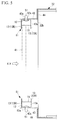
Fig. 3} Fig. 3 is a longitudinal sectional view illustrating an air suction side of the indoor unit of the embodiment of the present invention, and illustrates a state before filter rails are mounted. - {
Fig. 4} Fig. 4 is a longitudinal sectional view illustrating the air suction side of the indoor unit of the embodiment of the present invention, and illustrates a state after the filter rails are mounted. - {
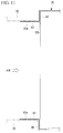
Fig. 5} Fig. 5 is a longitudinal sectional view illustrating an air suction side of a conventional indoor unit, and illustrates a state after the filter rails according to this embodiment are mounted. - {
Fig. 6} Fig. 6 is a longitudinal sectional view illustrating an installation state of the indoor unit of an air conditioner. - {
Fig. 7} Fig. 7 is a longitudinal sectional view illustrating the installation state of the indoor unit of the air conditioner. - {
Fig. 8} Fig. 8 is a longitudinal sectional view illustrating the installation state of the indoor unit of the air conditioner. - {
Fig. 9} Fig. 9 is a partially enlarged perspective view illustrating the conventional indoor unit. - {
Fig. 10} Fig. 10 is a longitudinal sectional view illustrating an air suction side of a conventional indoor unit, and illustrates a state after filter rails are mounted. - {
Fig. 11} Fig. 11 is a longitudinal sectional view illustrating an air suction side of a conventional indoor unit, and illustrates a state after a duct for suction is mounted. - Hereinafter, an air conditioner according to an embodiment of the present invention will be described with reference to the drawings.
- An
indoor unit 1 is a duct connection type indoor unit of an air conditioner, for example, a package air conditioner, and a first end of a duct for blowout is connected to an opening on an air blowout side of ahousing 2. Theindoor unit 1 is hung from a lower surface of a floor of an upstairs of a building or a lower surface of a beam provided blow the lower surface of the floor through a plurality of hanging bolts. In theindoor unit 1, in a case where a ceiling plate is bonded in a room, the whole of thehousing 2 is housed in the ceiling. On a second end side of the duct for blowout, a blowout port installed in a ceiling or the like is provided. Illustration and detailed description of an outdoor unit connected to theindoor unit 1 through a refrigerant pipe and an electric wire, and installed outdoors are omitted. - The
indoor unit 1 cools or heats air sucked from the inside of the room, by exchanging heat of the air with a refrigerant by use of a heat exchanger. Thereafter, the air, the heat of which has been exchanged, is blown out to the inside of the room. - The
indoor unit 1 has, for example, therectangular parallelepiped housing 2, as illustrated inFig. 1 . - The
housing 2 has a front plate (not illustrated) on an air blowout side, aback plate 3 on an air suction side, twoside plates 4 each having respective ends connected to the front plate and theback plate 3, atop plate 5 connected to respective upper ends of the front plate, theback plate 3, and theside plates 4, and abottom plate 6 connected to respective lower ends of the front plate, theback plate 3, and theside plates 4. - Inside the
housing 2, the heat exchanger (not illustrated) that exchanges heat of the indoor air with the refrigerant, and a plurality of sets of sirocco fans that circulate the indoor air, afan motor 8 that drives sirocco fans, a drain pan (not illustrated) that receives drain water generated by heat exchanger, a drain pump (not illustrated) that discharges drain water accumulated inside the drain pan, to the outside and the like, as illustrated inFig. 1 , are incorporated. Additionally, outside thehousing 2, a control box 9 that controls operation of theindoor unit 1 is provided on theside plate 4, for example. - In
housing 2, an opening for blowout (not illustrated) is formed in the front plate on the air blowout side. To the opening for blowout, the first end of the duct for blowout (not illustrated) is connected. On the second end side of the duct for blowout, a blowout port installed on the ceiling or the like is provided. - Furthermore, in the
housing 2, anopening 10 is formed in theback plate 3 on the air suction side. There are a case where aduct 35 for suction is connected to theopening 10, and a case where theduct 35 for suction is not connected to theopening 10. InFig. 4 , for convenience, both theduct 35 for suction and afilter 41 are illustrated by two-dot chain lines. However, only one of theduct 35 for suction and thefilter 41 is actually installed. - In a case where the first end of the
duct 35 for suction is connected to thehousing 2, a suction port on the second end side of theduct 35 for suction is connected, and indoor air sucked from the suction port is sent into thehousing 2 through theduct 35 for suction. On the other hand, in a case where theduct 35 for suction is not connected, thehousing 2 directly sucks air that has passed through a louver or the like, but thefilter 41 is installed in theopening 10 of thehousing 2. The area of thefilter 41 is substantially the same as the area of theopening 10, and dust contained in the air that passes through theopening 10 is removed. The thickness of thefilter 41 is, for example, 5 mm. - The
opening 10 which is formed in, for example, a rectangle is formed in theback plate 3 of thehousing 2, and filter rails 11 are mounted on theback plate 3 along theopening 10. The filter rails 11 are provided in parallel on an upper side and a lower side of theback plate 3 with theopening 10 sandwiched therebetween. Consequently, thefilter 41 is supported in a state where the upper and lower ends are sandwiched by the filter rails 11, as illustrated inFig. 4 . - Each of the filter rails 11 has a section formed in a U-shape, and is a long member in one direction. Each
filter rail 11 is configured by abottom plate 12, two side plates 13 (afirst side plate 13A and asecond side plate 13B) facing each other, and the like. Theside plates 13 are connected to thebottom plate 12 at the both ends of thebottom plate 12, and face each other. - When the filter rails 11 are installed on the
back plate 3 of thehousing 2, thefirst side plates 13A are fastened to theback plate 3 byscrews 14. Thefirst side plates 13A are formed withscrew holes 13a. Additionally, in theback plate 3, screwholes 3a for mounting the filter rails 11 are formed at such positions as to opposite to the screw holes 13a of thefirst side plates 13A. Eachscrew hole 3a is formed in a direction intersecting with a plate surface of theback plate 3, for example, in the vertical direction. - The
second side plates 13B are parallel to thefirst side plates 13A, and are formed withcutouts 13b at such positions as to correspond to thescrew holes 13a formed in thefirst side plates 13A, as illustrated inFig. 2 . Consequently, it is possible to allow thescrews 14 to pass through the screw holes 3a and thescrew holes 13a, and tighten thescrews 14 by a tool. Additionally, inconvenience that in screw tightening work, the tool cannot enter, or it is difficult to perform the work is not caused. - The screw holes 13a are formed in the
first side plates 13A, so that in thehousing 2 of theindoor unit 1, theback plate 3 mounted with the filter rails 11 may not be provided withconventional flanges 43 for duct connection (refer toFig. 9 to Fig. 11 ). Therefore, a section of theback plate 3 is not formed in an L-shape, but formed in a flat plate-like shape with no protruding part on the outside, in the vicinity of an edge of theopening 10, as illustrated inFig. 2 andFig. 3 . Then, a direction in which each of thescrews 14 is tightened is directed to the inside of thehousing 2 from the outer surface side of thehousing 2, and therefore tips of thescrews 14 do not protrude toward the outer surface of thehousing 2. Accordingly, it is not necessary to separately take measures such that a worker is not injured by thescrews 14 during transportation, and it is possible to reduce labor for ensuring safety. Particularly, in a case of a product in which providing of thefilter 41 in theopening 10 at an installation place without connecting theduct 35 for suction is the standard in shipment, even when the filter rails 11 are mounted at a factory, safety is ensured, and therefore a higher effect is obtained. - When the filter rails 11 are installed in the
back plate 3 of thehousing 2, thebottom plates 12 of the filter rails 11 are perpendicular to theback plate 3 of thehousing 2, and are parallel to the horizontal plane. Therefore, thebottom plates 12 of the filter rails 11 can be used for connection of theduct 35 for suction as illustrated inFig. 4 , similarly to theconventional flanges 43 for duct connection. Accordingly, theindoor unit 1 mounted with the filter rails 11 according to this embodiment can correspond both the case where theduct 35 for suction is connected to thehousing 2, and the case where theduct 35 for suction is not connected to the housing. - In the
bottom plates 12 of the filter rails 11,screw holes 12a may be formed in addition to the screw holes 13a of thefirst side plate 13A, as illustrated inFig. 5 . Consequently, as illustrated inFig. 5 , the filter rails 11 according to this embodiment can be mounted on theconventional flanges 43 for duct connection. Theflanges 43 for duct connection are formed withscrew holes 43a at such positions as to correspond to thescrew holes 12a. Therefore, filter rails do not need to be separately prepared for the conventionalindoor unit 31 in which theflanges 43 for duct connection are mounted on aback plate 44 of thehousing 32, and it is possible to share the component. - Additionally, a difference between the
conventional back plate 44 formed with theflanges 43 for duct connection, and theback plate 3 according to this embodiment, which is not formed with the flange for duct connection is whether or not bent portions for flanges for duct connection exist. Therefore, in each of the manufacturing processes of theindoor units back plate housing opening back plate indoor unit indoor units - Inside the filter rails 11,
buffer members 15 whose quality of materials is foamed rubber or the like are provided. Thefilter 41 is supported by the filter rails 11 through thebuffer members 15. Consequently, it is possible to reduce vibration transmitted from thehousing 2 to thefilter 41. - A distance between a lowermost end of the
filter rail 11 installed on the upper side of thehousing 2 and an uppermost end of thefilter rail 11 installed on the lower side is slightly shorter than the height of thefilter 41. In a case where thefilter 41 is installed in the filter rails 11, in a state where thefilter 41 is bent in a height direction to form a V-shaped section, and the height is made to be lower than an interval between both the filter rails 11, thefilter 41 is inserted between both the filter rails 11. Then, thefilter 41 bent in the V-shape is released to be formed in a straight shape, and the upper and lower ends of thefilter 41 are fitted in respective groove parts of the filter rails 11. - Now, a method for mounting the filter rails 11 on the
housing 2, and a method for installing thefilter 41 or theduct 35 for suction will be described. - First, a case where the filter rails 11 are mounted on the
back plate 3 according to this embodiment, which are not formed with the flanges for duct connection in the state ofFig. 3 will be described. In this case, screwholes 3a formed in the flat plate-like back plate 3, and thescrew holes 13a formed in thefirst side plates 13A of the filter rails 11 are made to coincide with each other. Then, eachscrew 14 is inserted into both the screw holes 3a and 13a to be tightened. Consequently, the filter rails 11 are mounted on theback plate 3. This work is performed for both thefilter rail 11 on the upper side of theback plate 3 and thefilter rail 11 on the lower side. - Thereafter, in a case where the
filter 41 is mounted, thefilter 41 is inserted between both the filter rails 11 while being bent, and the upper and lower ends of thefilter 41 are fitted in the respective groove parts. On the other hand, in a case where theduct 35 for suction is connected, thebottom plates 12 of the filter rails 11, and the vertically installedflanges 16 for duct connection (refer toFig. 1 ) are utilized. For example, an inner surface of theduct 35 for suction is brought into contact with outer surfaces of thebottom plates 12 of the filter rails 11, and outer surfaces of theflanges 16 for duct connection, theduct 35 for suction is connected to the filter rails 11 and theflanges 16 for duct connection from the outside of theduct 35 for suction by using a band or a tapping screw. Consequently, theduct 35 for suction is fastened to thehousing 2. - Now, a case where the filter rails 11 are mounted on the
conventional back plate 44 formed with theflanges 43 for duct connection will be described with reference toFig. 5 . In this case, thescrew holes 43a formed in theflanges 43 for duct connection, screwholes 12a formed in thebottom plates 12 of the filter rails 11 are made to coincide with each other. Then, eachscrew 51 is inserted into both the screw holes 43a and 12a to be tightened. Consequently, the filter rails 11 are mounted on theflanges 43 for duct connection. This work is performed for both thefilter rail 11 on the upper side and thefilter rail 11 on the lower side. - Thereafter, in a case where the
filter 41 is mounted, thefilter 41 is inserted while being bent between both the filter rails 11, and the upper and lower ends of thefilter 41 are fitted in the respective groove parts, in a similar manner to the above case according to this embodiment. On the other hand, in a case where theduct 35 for suction is connected, the filter rails 11 according to this embodiment are not mounted on theflanges 43 for duct connection, as illustrated inFig. 11 . In this case, horizontally installedflanges 43 for duct connection, and vertically installedflanges 46 for duct connection (refer toFig. 9 ) are utilized. For example, the inner surface of theduct 35 for suction is brought into contact with outer surfaces of theflanges duct 35 for suction is connected to theflanges duct 35 for suction by using a band or a tapping screw. - As described above, according to this embodiment, as illustrated in
Fig. 4 , a direction in which each of the screws of the filter rails 11 is tightened is directed to the inside of thehousing 2, and therefore the tips of thescrews 14 do not protrude to the outer surface of thehousing 2. Accordingly, it is not necessary to separately take measures such that a worker is not injured by thescrews 14 during transportation, and it is possible to reduce labor for ensuring safety. - Additionally, the
bottom plates 12 of the filter rails 11 according to this embodiment can be used for the connection of theduct 35 for suction, similarly to theconventional flanges 43 for duct connection. Accordingly, theindoor unit 1 mounted with the filter rails 11 according to this embodiment can correspond to both the case where theduct 35 for suction is connected to thehousing 2, and the case where theduct 35 for suction is not connected to thehousing 2. - Furthermore, in the
bottom plates 12 of the filter rails 11 according to this embodiment, in a case where thescrew holes 12a are formed in addition to the screw holes 13a of thefirst side plates 13A, the filter rails 11 according to this embodiment can be mounted also on the conventionalindoor unit 31 in which theflanges 43 for duct connection are mounted on theback plate 44 of thehousing 32. Accordingly, it is possible to share the components, and a plurality of types of filter rails do not need to be prepared corresponding to a plurality of types of indoor units (for example, the aboveindoor unit 1 and indoor unit 31). - Moreover, a difference between the
conventional back plate 44 formed with theflanges 43 for duct connection, and theback plate 3 according to this embodiment, which is not formed with the flange for duct connection is whether or not the bent portions for flanges for duct connection exist. Therefore, it is possible to flexibly cope with change in the numbers of manufacturing of the indoor units due to increase or reduction of order. -
- 1, 31
- indoor unit
- 2, 32
- housing
- 3
- back plate (outer plate)
- 3a, 43a
- screw hole
- 4
- side plate
- 5
- top plate
- 6
- bottom plate
- 7
- sirocco fan
- 8
- fan motor
- 9
- control box
- 10
- opening (opening part)
- 11
- filter rail (filter support for an indoor unit)
- 12
- bottom plate (third plate part)
- 12a
- screw hole (second screw hole)
- 13
- side plate
- 13A
- first side plate (first plate part)
- 13B
- second side plate (second plate part)
- 13a
- screw hole (first screw hole)
- 13b
- cutout
- 14
- screw (first screw)
- 15, 45
- buffer member
- 16, 46
- flange for duct connection
- 32a, 32b
- opening
- 33
- duct for blowout
- 34
- blowout port
- 35
- duct for suction
- 36
- suction port
- 37
- louver
- 41
- filter
- 42
- filter rail
- 42a
- bottom plate
- 43
- flange for duct connection (flange part)
- 44
- back plate
- 51
- screw (second screw)
Claims (6)
- A filter support for an indoor unit mounted on an outer plate of a housing of an indoor unit along an opening part formed on an air suction side at the outer plate of the housing, the filter support for an indoor unit supporting a filter installed in the opening part, comprising:a first plate part installed along the outer plate of the housing; anda second plate part installed so as to face the first plate part, whereinthe first plate part and the second plate part support the filter by sandwiching the filter therebetween, andthe first plate part is coupled to the outer plate by a first screw that penetrates the outer plate and the first plate part from outside to inside.
- The filter support for an indoor unit according to claim 1, wherein the second plate part is formed with a cutout part corresponding to a coupling position of the first screw.
- The filter support for an indoor unit according to claim 1 or 2, further comprising a third plate part installed in a direction intersecting with the outer plate.
- The filter support for an indoor unit according to claim 3, wherein
the first plate part is formed with a first screw hole for allowing the first screw to penetrate, and
the third plate part is formed with a second screw hole for allowing a second screw to penetrate, the second screw coupling a flange part provided in the direction intersecting with the outer plate, and the third plate part. - An indoor unit comprising the filter support for an indoor unit according to any one of claims 1 to 4.
- An air conditioner comprising:the indoor unit according to claim 5; andan outdoor unit connected to the indoor unit by a refrigerant pipe.
Applications Claiming Priority (1)
| Application Number | Priority Date | Filing Date | Title |
|---|---|---|---|
| JP2015034092A JP6532696B2 (en) | 2015-02-24 | 2015-02-24 | Filter support for indoor unit, indoor unit and air conditioner |
Publications (1)
| Publication Number | Publication Date |
|---|---|
| EP3062033A1 true EP3062033A1 (en) | 2016-08-31 |
Family
ID=55661068
Family Applications (1)
| Application Number | Title | Priority Date | Filing Date |
|---|---|---|---|
| EP16156522.1A Withdrawn EP3062033A1 (en) | 2015-02-24 | 2016-02-19 | Filter support for indoor unit, indoor unit, and air conditioner |
Country Status (3)
| Country | Link |
|---|---|
| EP (1) | EP3062033A1 (en) |
| JP (1) | JP6532696B2 (en) |
| AU (1) | AU2016201016B2 (en) |
Cited By (1)
| Publication number | Priority date | Publication date | Assignee | Title |
|---|---|---|---|---|
| US20200164297A1 (en) * | 2018-11-28 | 2020-05-28 | Baidu Usa Llc | Tool-less air filter attaching mechanism for planning and control system of autonomous driving vehicles |
Families Citing this family (2)
| Publication number | Priority date | Publication date | Assignee | Title |
|---|---|---|---|---|
| US11480363B2 (en) * | 2020-06-30 | 2022-10-25 | Haier Us Appliance Solutions, Inc. | Filter assembly for an air conditioning appliance |
| JP7855845B2 (en) * | 2021-10-28 | 2026-05-11 | 株式会社ゼネラル | air conditioner |
Citations (6)
| Publication number | Priority date | Publication date | Assignee | Title |
|---|---|---|---|---|
| JPS6219525U (en) | 1985-07-19 | 1987-02-05 | ||
| US4781526A (en) * | 1987-10-29 | 1988-11-01 | Clarence Mead | Fan and filter combination |
| US5690719A (en) * | 1995-10-19 | 1997-11-25 | Hodge; Joseph | Removable filter for a forced air duct grill |
| US5964910A (en) * | 1998-01-05 | 1999-10-12 | Keele; Rex A. | Diffusing filter for downdraft air moving appliances |
| US20050034472A1 (en) * | 2003-08-12 | 2005-02-17 | Hong Sang Min | Air conditioner |
| US20080229723A1 (en) * | 2007-03-22 | 2008-09-25 | Randall Stepp | Forced Air Duct End Filter Assembly |
Family Cites Families (5)
| Publication number | Priority date | Publication date | Assignee | Title |
|---|---|---|---|---|
| US4027498A (en) * | 1976-04-02 | 1977-06-07 | Mclean Engineering Midwest | Air conditioner |
| JP2601234B2 (en) * | 1995-03-27 | 1997-04-16 | 株式会社日立製作所 | Air conditioner |
| JPH09250774A (en) * | 1996-03-19 | 1997-09-22 | Fujitsu General Ltd | Air conditioner |
| JP2002115898A (en) * | 2000-10-10 | 2002-04-19 | Mitsubishi Heavy Ind Ltd | Duct type air conditioner and control method thereof |
| CN101210708A (en) * | 2006-12-28 | 2008-07-02 | 乐金电子(天津)电器有限公司 | Pipeline type commercial air-conditioner indoor set |
-
2015
- 2015-02-24 JP JP2015034092A patent/JP6532696B2/en active Active
-
2016
- 2016-02-18 AU AU2016201016A patent/AU2016201016B2/en active Active
- 2016-02-19 EP EP16156522.1A patent/EP3062033A1/en not_active Withdrawn
Patent Citations (6)
| Publication number | Priority date | Publication date | Assignee | Title |
|---|---|---|---|---|
| JPS6219525U (en) | 1985-07-19 | 1987-02-05 | ||
| US4781526A (en) * | 1987-10-29 | 1988-11-01 | Clarence Mead | Fan and filter combination |
| US5690719A (en) * | 1995-10-19 | 1997-11-25 | Hodge; Joseph | Removable filter for a forced air duct grill |
| US5964910A (en) * | 1998-01-05 | 1999-10-12 | Keele; Rex A. | Diffusing filter for downdraft air moving appliances |
| US20050034472A1 (en) * | 2003-08-12 | 2005-02-17 | Hong Sang Min | Air conditioner |
| US20080229723A1 (en) * | 2007-03-22 | 2008-09-25 | Randall Stepp | Forced Air Duct End Filter Assembly |
Cited By (2)
| Publication number | Priority date | Publication date | Assignee | Title |
|---|---|---|---|---|
| US20200164297A1 (en) * | 2018-11-28 | 2020-05-28 | Baidu Usa Llc | Tool-less air filter attaching mechanism for planning and control system of autonomous driving vehicles |
| US11890564B2 (en) * | 2018-11-28 | 2024-02-06 | Baidu Usa Llc | Tool-less air filter attaching mechanism for planning and control system of autonomous driving vehicles |
Also Published As
| Publication number | Publication date |
|---|---|
| AU2016201016B2 (en) | 2017-06-29 |
| JP2016156551A (en) | 2016-09-01 |
| AU2016201016A1 (en) | 2016-09-08 |
| JP6532696B2 (en) | 2019-06-19 |
Similar Documents
| Publication | Publication Date | Title |
|---|---|---|
| CN104976699B (en) | The outdoor unit of air conditioner | |
| US8978393B2 (en) | Outdoor unit of air conditioner | |
| US11131479B2 (en) | Air-conditioning apparatus indoor unit | |
| EP1666801A1 (en) | Outdoor unit of air conditioner | |
| CN204063353U (en) | The off-premises station of air conditioner | |
| AU2016201016B2 (en) | Filter support for indoor unit, indoor unit, and air conditioner | |
| US11421912B2 (en) | Packing system including packing material for air conditioner and air conditioner | |
| JP2012233646A (en) | Ceiling embedded type air conditioner | |
| KR101815380B1 (en) | ceiling type air conditioner | |
| WO2019198151A1 (en) | Outdoor unit for air conditioner | |
| JP6410211B2 (en) | Embedded ceiling air conditioner | |
| JP6323203B2 (en) | Duct type air conditioner | |
| JP2011208859A (en) | Ceiling installation type air conditioner | |
| JP5894816B2 (en) | Built-in air conditioner | |
| US20180003407A1 (en) | Insulated register box with boot rail adaptor | |
| JP2018035956A (en) | Installation structure of air conditioner | |
| AU2016420909B2 (en) | Heat exchanger unit and air-conditioning apparatus | |
| JP2015206505A (en) | duct type air conditioner | |
| JP5963507B2 (en) | Air conditioner | |
| JP4704226B2 (en) | Ceiling cassette type air conditioner | |
| CN206890780U (en) | Ceiling embedded air conditioner | |
| JP6381886B2 (en) | Air conditioner | |
| JP6019217B2 (en) | Air conditioner | |
| US20190195529A1 (en) | Indoor unit of air-conditioning apparatus | |
| CN113874663B (en) | Indoor unit of air conditioner and attachment device for indoor unit |
Legal Events
| Date | Code | Title | Description |
|---|---|---|---|
| PUAI | Public reference made under article 153(3) epc to a published international application that has entered the european phase |
Free format text: ORIGINAL CODE: 0009012 |
|
| AK | Designated contracting states |
Kind code of ref document: A1 Designated state(s): AL AT BE BG CH CY CZ DE DK EE ES FI FR GB GR HR HU IE IS IT LI LT LU LV MC MK MT NL NO PL PT RO RS SE SI SK SM TR |
|
| AX | Request for extension of the european patent |
Extension state: BA ME |
|
| 17P | Request for examination filed |
Effective date: 20170228 |
|
| RBV | Designated contracting states (corrected) |
Designated state(s): AL AT BE BG CH CY CZ DE DK EE ES FI FR GB GR HR HU IE IS IT LI LT LU LV MC MK MT NL NO PL PT RO RS SE SI SK SM TR |
|
| RAP1 | Party data changed (applicant data changed or rights of an application transferred) |
Owner name: MITSUBISHI HEAVY INDUSTRIES THERMAL SYSTEMS, LTD. |
|
| STAA | Information on the status of an ep patent application or granted ep patent |
Free format text: STATUS: THE APPLICATION HAS BEEN WITHDRAWN |
|
| 18W | Application withdrawn |
Effective date: 20191107 |