EP3062020A1 - Igniter position for a combustor of a gas turbine engine - Google Patents
Igniter position for a combustor of a gas turbine engine Download PDFInfo
- Publication number
- EP3062020A1 EP3062020A1 EP16157297.9A EP16157297A EP3062020A1 EP 3062020 A1 EP3062020 A1 EP 3062020A1 EP 16157297 A EP16157297 A EP 16157297A EP 3062020 A1 EP3062020 A1 EP 3062020A1
- Authority
- EP
- European Patent Office
- Prior art keywords
- igniter
- combustor
- area
- free space
- distal end
- Prior art date
- Legal status (The legal status is an assumption and is not a legal conclusion. Google has not performed a legal analysis and makes no representation as to the accuracy of the status listed.)
- Granted
Links
Images


Classifications
-
- F—MECHANICAL ENGINEERING; LIGHTING; HEATING; WEAPONS; BLASTING
- F23—COMBUSTION APPARATUS; COMBUSTION PROCESSES
- F23R—GENERATING COMBUSTION PRODUCTS OF HIGH PRESSURE OR HIGH VELOCITY, e.g. GAS-TURBINE COMBUSTION CHAMBERS
- F23R3/00—Continuous combustion chambers using liquid or gaseous fuel
- F23R3/002—Wall structures
-
- F—MECHANICAL ENGINEERING; LIGHTING; HEATING; WEAPONS; BLASTING
- F02—COMBUSTION ENGINES; HOT-GAS OR COMBUSTION-PRODUCT ENGINE PLANTS
- F02C—GAS-TURBINE PLANTS; AIR INTAKES FOR JET-PROPULSION PLANTS; CONTROLLING FUEL SUPPLY IN AIR-BREATHING JET-PROPULSION PLANTS
- F02C7/00—Features, components parts, details or accessories, not provided for in, or of interest apart form groups F02C1/00 - F02C6/00; Air intakes for jet-propulsion plants
- F02C7/26—Starting; Ignition
- F02C7/264—Ignition
-
- F—MECHANICAL ENGINEERING; LIGHTING; HEATING; WEAPONS; BLASTING
- F23—COMBUSTION APPARATUS; COMBUSTION PROCESSES
- F23R—GENERATING COMBUSTION PRODUCTS OF HIGH PRESSURE OR HIGH VELOCITY, e.g. GAS-TURBINE COMBUSTION CHAMBERS
- F23R3/00—Continuous combustion chambers using liquid or gaseous fuel
- F23R3/42—Continuous combustion chambers using liquid or gaseous fuel characterised by the arrangement or form of the flame tubes or combustion chambers
- F23R3/60—Support structures; Attaching or mounting means
Definitions
- the present disclosure relates to gas turbine engines and, in particular, to combustor and igniter configurations for gas turbine engines.
- Gas turbine engines are required to operate efficiently during operation and flight. These engines create a tremendous amount of force and generate high levels of heat. As such, components of these engines are subjected to high levels of stress, temperature and pressure. It is necessary to provide components that can withstand the demands of a gas turbine engine. It is also desirable to provide components with increased operating longevity.
- FIG. 1 depicts a conventional configuration of a combustor 100 including an igniter 105 with the igniter tip 106 protruding into the combustor cavity 110.
- Many conventional combustor and gas turbine engines include an igniter position with the igniter tip 106 protruding into the combustor cavity 110. This configuration can lead to deformation of the igniter due to extreme temperatures within cavity 110. As a result, the igniter 105, and in particular the igniter tip 106, may deform over time or "mushroom" due to the environment within cavity 110.
- igniters Some components of gas turbine engines, such as igniters, are designed to be line replacement units (LRUs). Deformation of the igniter 105, and especially mushrooming of igniter tip 106, may result in great difficulty when removal of igniter 105 is needed. In some cases, igniter deformation will result in a complete overhaul of the engine to remove and replace igniters at a great expense. Accordingly, there is a desire to provide a configuration that allows for operation of a combustor and igniter which overcomes the aforementioned drawbacks. There is also a desire to improve the configuration of gas turbine engines and combustors.
- LRUs line replacement units
- One embodiment is directed to a combustor for a gas turbine engine, the combustor including a combustor shell enclosing a first area of free space and an igniter for the combustor shell, the igniter including a distal end.
- the combustor also includes one or more elements configured to retain the igniter and to interface with the combustor shell, wherein the one or more elements define a second area of free space, and wherein the igniter is retained within the second area of free space such that the distal end of the igniter is recessed from the first area of free space.
- the first area of free space is defined by the inner surface of the combustor shell and one or more liners mounted to an interior of the combustor shell.
- the igniter is recessed from the first area of free space by a fixed distance.
- the first area of free space is separate from the second area of free space.
- the one or more elements extend into the combustor shell.
- the igniter is offset from a boundary between the first area of free space and the second area of free space by a predetermined distance.
- the distal end of the igniter is removed from a direct path of gas flow within the combustor.
- the combustor shell is at least one of an annular and sectional combustor shell.
- the distal end of the igniter is recessed by at least one of a parallel and angled offset from the first area of free space.
- the distal end of the igniter is angularly offset from the first area of free space within the range of 0 - 45 degrees.
- Another embodiment is directed to a combustor for a gas turbine engine, the combustor including a combustor shell enclosing a first area of free space and an igniter for the combustor shell, the igniter including a distal end.
- the combustor also includes one or more elements configured to retain the igniter and interface with the combustor shell, wherein the one or more elements define a boundary between the combustor shell and the one or more elements, and wherein the igniter is retained within the one or more elements such that the distal end of the igniter is recessed from the boundary.
- the first area of free space is defined by the inner surface of the combustor shell and one or more liners mounted to the interior of the combustor shell.
- the igniter is recessed from the boundary by a fixed distance.
- the boundary is a plane between the first area of free space and the area defined by the one or more elements.
- the one or more elements extend into the combustor shell.
- the igniter is offset from the boundary by a predetermined distance.
- the distal end of the igniter is removed from a direct path of gas flow within the combustor.
- the combustor shell is at least one of an annular and sectional combustor shell.
- the distal end of the igniter is recessed by at least one of a parallel and angled offset from the boundary.
- the distal end of the igniter is angularly offset from the boundary within the range of 0 - 45 degrees.
- a configuration for a combustor including a combustor shell, igniter, and one or more elements to support and/or position an igniter relative to a combustor cavity.
- a combustor shell, igniter, and igniter support elements may be configured to allow for positioning of an igniter which reduces the exposure of the igniter to hot gas flow.
- the terms “a” or “an” shall mean one or more than one.
- the term “plurality” shall mean two or more than two.
- the term “another” is defined as a second or more.
- the terms “including” and/or “having” are open ended (e.g., comprising).
- the term “or” as used herein is to be interpreted as inclusive or meaning any one or any combination. Therefore, “A, B or C” means “any of the following: A; B; C; A and B; A and C; B and C; A, B and C". An exception to this definition will occur only when a combination of elements, functions, steps or acts are in some way inherently mutually exclusive.
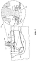
- FIG. 2 depicts a cross-sectional representation of a combustor 200 according to one or more embodiments.
- Combustor 200 includes a combustor shell 205, one or more elements shown as support elements 215, and igniter 210.
- Igniter 210 may be retained relative to combustor shell 205 and/or supported by support elements 215.
- the configuration of combustor 200 may allow for positioning of an igniter within combustor shell 205 to prevent deformation of the igniter 210 and improve life-on-wing for igniters.
- igniter 210 may be recessed from a boundary to reduce high heat exposure of distal end 211.
- Recessing igniter 210 decreases structural deformities to the igniter, decreases heat exposure, and can increase component efficiency by reducing required parasitic cooling flow. Recessing igniter 210 can improve ignition performance. Additionally, structural deformities of igniter 210 increase the cost of repairs and maintenance of gas turbine engines.
- Combustor shell 205 encloses a first area of free space 220 within the combustor shell 205.
- the combustor shell 205 is at least one of an annular and sectional combustor shell.
- the first area of free space 220 is defined by the inner surface of the combustor shell 205 and one or more liners mounted to the interior of the combustor shell.
- Igniter 210 for combustor shell 205 may be mounted, by support elements 215, relative to the combustor shell 205 to ignite fuel and air mixture within the combustor.
- igniter 210 includes a distal end, the distal end may include one or more electrodes for ignition of the gas flow path within the combustor shell 205.
- the distal end of the igniter 210 is a substantially flat surface including an electrode.
- Igniter 210 may be a cylindrically shaped device.
- Combustor 200 includes support elements 215 configured to retain the igniter 210 and to interface with the combustor shell 205.
- Support element 215 can define a second area of free space.
- support elements 215 extend into the combustor shell 205.
- Support elements 215 may include one or more of an igniter tube, and one or more support rings.
- FIG. 2 An enlarged view of the combustor shell 205 and support elements 215 is shown as 250 in FIG. 2 .
- Combustor shell is shown with a liner 206.
- support elements 215 extend into an opening with the combustor shell 205.
- Support elements 215 define a second area of free space 221.
- first area of free space 220 and second area of free space 221 do not overlap.
- Igniter 210 is retained within the second area of free space 221 such that the distal end 211 of the igniter 210 is recessed from the first area of free space 220. Recessing the igniter 210 can remove the distal end 211 out of the gas flow path such that the area of the igniter 210 that is exposed to high gas path temperatures is reduced or minimized.
- first area of free space 220 and second area of free space 221 is shown as 222.
- face of igniter 210 is shown recessed to position 223, wherein position 223 is offset and/or recessed from first area of free space 220.
- face of igniter 210 is shown recessed to positioned 223, wherein position 223 is offset and/or recessed from boundary 222.
- combustor 200 may allow for positioning and/or placement of an igniter 210 relative to a first area of free space 220 within combustor shell 205.
- Support elements 215 can retain igniter 210 within the second area of free space such that the distal end of the igniter is recessed from the first area of free space 220.
- recessed can relate to a fixed distance of displacement from the first area of free space 220.
- the first area of free space 220 is separate from the second area of free space.
- the distal end of the igniter may be recessed by at least one of a parallel and angled offset from the first area of free space 220.
- the igniter is offset from a boundary between the first area of free space and the second area of free space by a predetermined distance. As such, the distal end of the igniter 210 is removed from a direct path of gas flow within the combustor
- combustor 200 may allow for positioning and/or placement of an igniter 210 relative to a boundary between first area of free space 220 and support elements 215.
- Igniter 210 may be recessed a fixed distance of displacement from the boundary 222 to position 223.
- Recess plane 223 is offset from the boundary 222 between by a predetermined distance. In that fashion, the distal end 211 of the igniter 210 is recessed by at least one of a parallel and angled offset from the boundary 222.
- Support elements 215 can retain igniter 210 within the second area of free space such that the distal end of the igniter is recessed from boundary 222.
- recessed can relate to a fixed distance of displacement from the first area of free space 220.
- the first area of free space 220 is separate from the second area of free space 221.
- the distal end of the igniter 210 may be recessed by at least one of a parallel and angled offset from the boundary 222.
- igniter 210 is offset from a boundary between the first area of free space and the second area of free space by a predetermined distance. As such, the distal end of the igniter 210 is removed from a direct path of gas flow within the combustor 200.
- boundary 222 is a plane between the first area of free space 220 and the area defined by the support elements 215.
- offset of igniter 210 from first area of free space 220, or boundary 222 relates to a set point for positioning igniter 210.
- igniter 210 is offset a fixed distance of 0.036 inches (around 0.91 mm).
- igniter 210 is offset a fixed distance within the range of 0.015 to 0.060 inches (around 0.38 mm to 1.52 mm).
- igniter 210 is offset a fixed distance within a given tolerance.
- the offset of igniter 210 may vary during installation, based on the installer or other factors.
- support elements 215 may be configured to allow for positioning to an offset, and/or one or more positions within a tolerance of the fixed distance.
- FIGS. 3A - 3B depict cross-sectional representations of igniter configurations for a gas turbine engine according to one or more embodiments.
- FIG. 3A depicts a cross-sectional representation of igniter configuration 300 for a gas turbine engine according for combustor shell 302, igniter 304, and support elements 303.
- Combustor shell 302 encloses a first area of free space, shown by 307.
- Igniter 304 for the combustor shell 302 includes a distal end 306.
- Distal end 306 of igniter 304 is a substantially flat surface with an electrode. According to one embodiment, distal end 306 of igniter 304 is offset from the first area of free space a fixed distance within the range of 0.015 to 0.055 inches (around 0.38 mm to 1.40 mm).
- Support elements 303 are configured to retain the igniter 304 and interface with the combustor shell 302. Support elements 303 can extend into an opening with the combustor shell 302. Support elements 303 define a second area of free space 308. First area of free space 307 and second area of free space 308 do not overlap. Igniter 304 is retained within the second area of free space 308 such that the distal end 306 of the igniter 304 is recessed from the first area of free space 307. In another embodiment, the support elements 303 define a boundary 323 between the combustor shell 302 and support elements 303. Boundary 323 prevents overlapping of the combustor shell 302 and igniter tube 303.
- Igniter 304 is retained within the igniter tube 303 such that the distal end 306 of the igniter 304 is recessed from the boundary 323.
- Recessed is offset from the boundary 323 a predetermined distance. Recessed can also be near but out of the gas flow. Near but out of the gas flow can be not exposed to a high temperature but close enough to allow ignition of combustible gasses.
- FIG. 3B depicts a cross-sectional representation of a combustor 350 for a gas turbine engine according to one or more embodiments.
- Igniter 304 is retained within the igniter tube 303 such that the distal end 306 of the igniter 304 is recessed from the boundary 323.
- Recessed is offset from the boundary 323 a predetermined distance. Recessed can also be near but out of the gas flow.
- Igniter 210 recessed can also be where distal end 206 surface is positioned parallel or at a predetermined angled 330. According to one embodiment, distal end 306 of igniter 304 is angularly offset from the boundary within the range of 0 - 45 degrees.
- FIG. 4 depicts graphical representation of an igniter for a combustor of a gas turbine engine according to one or more embodiments.
- Igniter 400 includes a distal end 445. Positioning igniter 400 in a recessed position reduces extreme high heat exposure of distal end 445 and can remove the igniter 400 from the direct flow path of the fuel and gas mixture of combustor. Reduced exposure of distal tip 445 to extreme high temperature causes less structural deformities 441 and increased operating longevity.
Landscapes
- Engineering & Computer Science (AREA)
- Chemical & Material Sciences (AREA)
- Combustion & Propulsion (AREA)
- Mechanical Engineering (AREA)
- General Engineering & Computer Science (AREA)
- Turbine Rotor Nozzle Sealing (AREA)
Abstract
Description
- The present disclosure relates to gas turbine engines and, in particular, to combustor and igniter configurations for gas turbine engines.
- Gas turbine engines are required to operate efficiently during operation and flight. These engines create a tremendous amount of force and generate high levels of heat. As such, components of these engines are subjected to high levels of stress, temperature and pressure. It is necessary to provide components that can withstand the demands of a gas turbine engine. It is also desirable to provide components with increased operating longevity.
-
FIG. 1 depicts a conventional configuration of acombustor 100 including anigniter 105 with theigniter tip 106 protruding into thecombustor cavity 110. Many conventional combustor and gas turbine engines include an igniter position with theigniter tip 106 protruding into thecombustor cavity 110. This configuration can lead to deformation of the igniter due to extreme temperatures withincavity 110. As a result, theigniter 105, and in particular theigniter tip 106, may deform over time or "mushroom" due to the environment withincavity 110. - Some components of gas turbine engines, such as igniters, are designed to be line replacement units (LRUs). Deformation of the
igniter 105, and especially mushrooming ofigniter tip 106, may result in great difficulty when removal ofigniter 105 is needed. In some cases, igniter deformation will result in a complete overhaul of the engine to remove and replace igniters at a great expense. Accordingly, there is a desire to provide a configuration that allows for operation of a combustor and igniter which overcomes the aforementioned drawbacks. There is also a desire to improve the configuration of gas turbine engines and combustors. - Disclosed and claimed herein are combustor and igniter configurations for gas turbine engines. One embodiment is directed to a combustor for a gas turbine engine, the combustor including a combustor shell enclosing a first area of free space and an igniter for the combustor shell, the igniter including a distal end. The combustor also includes one or more elements configured to retain the igniter and to interface with the combustor shell, wherein the one or more elements define a second area of free space, and wherein the igniter is retained within the second area of free space such that the distal end of the igniter is recessed from the first area of free space.
- In one embodiment, the first area of free space is defined by the inner surface of the combustor shell and one or more liners mounted to an interior of the combustor shell.
- In one embodiment, the igniter is recessed from the first area of free space by a fixed distance.
- In one embodiment, the first area of free space is separate from the second area of free space.
- In one embodiment, the one or more elements extend into the combustor shell.
- In one embodiment, the igniter is offset from a boundary between the first area of free space and the second area of free space by a predetermined distance.
- In one embodiment, the distal end of the igniter is removed from a direct path of gas flow within the combustor.
- In one embodiment, the combustor shell is at least one of an annular and sectional combustor shell.
- In one embodiment, the distal end of the igniter is recessed by at least one of a parallel and angled offset from the first area of free space.
- In one embodiment, the distal end of the igniter is angularly offset from the first area of free space within the range of 0 - 45 degrees.
- Another embodiment is directed to a combustor for a gas turbine engine, the combustor including a combustor shell enclosing a first area of free space and an igniter for the combustor shell, the igniter including a distal end. The combustor also includes one or more elements configured to retain the igniter and interface with the combustor shell, wherein the one or more elements define a boundary between the combustor shell and the one or more elements, and wherein the igniter is retained within the one or more elements such that the distal end of the igniter is recessed from the boundary.
- In one embodiment, the first area of free space is defined by the inner surface of the combustor shell and one or more liners mounted to the interior of the combustor shell.
- In one embodiment, the igniter is recessed from the boundary by a fixed distance.
- In one embodiment, the boundary is a plane between the first area of free space and the area defined by the one or more elements.
- In one embodiment, the one or more elements extend into the combustor shell.
- In one embodiment, the igniter is offset from the boundary by a predetermined distance.
- In one embodiment, the distal end of the igniter is removed from a direct path of gas flow within the combustor.
- In one embodiment, the combustor shell is at least one of an annular and sectional combustor shell.
- In one embodiment, the distal end of the igniter is recessed by at least one of a parallel and angled offset from the boundary.
- In one embodiment, the distal end of the igniter is angularly offset from the boundary within the range of 0 - 45 degrees.
- Other aspects, features, and techniques will be apparent to one skilled in the relevant art in view of the following detailed description of the embodiments.
- The features, objects, and advantages of the present disclosure will become more apparent from the detailed description set forth below when taken in conjunction with the drawings in which like reference characters identify correspondingly throughout and wherein:
-
FIG. 1 depicts a graphical representation of a conventional combustor configuration for a gas turbine engine; -
FIG. 2 depicts a cross-sectional representation of a combustor for a gas turbine engine according to one or more embodiments; -
FIGS. 3A - 3B depict cross-sectional representations of igniter configurations for a gas turbine engine according to one or more embodiments; and -
FIG. 4 depicts graphical representation of an igniter for a combustor of a gas turbine engine according to one or more embodiments. - One aspect of this disclosure relates to configurations for an igniter relative to a combustor according to one or more embodiments. In one embodiment, a configuration for a combustor is provided including a combustor shell, igniter, and one or more elements to support and/or position an igniter relative to a combustor cavity. A combustor shell, igniter, and igniter support elements may be configured to allow for positioning of an igniter which reduces the exposure of the igniter to hot gas flow.
- As used herein, the terms "a" or "an" shall mean one or more than one. The term "plurality" shall mean two or more than two. The term "another" is defined as a second or more. The terms "including" and/or "having" are open ended (e.g., comprising). The term "or" as used herein is to be interpreted as inclusive or meaning any one or any combination. Therefore, "A, B or C" means "any of the following: A; B; C; A and B; A and C; B and C; A, B and C". An exception to this definition will occur only when a combination of elements, functions, steps or acts are in some way inherently mutually exclusive.
- Reference throughout this document to "one embodiment", "certain embodiments", "an embodiment", or similar term means that a particular feature, structure, or characteristic described in connection with the embodiment is included in at least one embodiment. Thus, the appearances of such phrases in various places throughout this specification are not necessarily all referring to the same embodiment. Furthermore, the particular features, structures, or characteristics may be combined in any suitable manner on one or more embodiments without limitation.
-
FIG. 2 depicts a cross-sectional representation of acombustor 200 according to one or more embodiments.Combustor 200 includes acombustor shell 205, one or more elements shown assupport elements 215, andigniter 210.Igniter 210 may be retained relative tocombustor shell 205 and/or supported bysupport elements 215. The configuration ofcombustor 200 may allow for positioning of an igniter withincombustor shell 205 to prevent deformation of theigniter 210 and improve life-on-wing for igniters. According to one embodiment,igniter 210 may be recessed from a boundary to reduce high heat exposure ofdistal end 211. Recessingigniter 210 decreases structural deformities to the igniter, decreases heat exposure, and can increase component efficiency by reducing required parasitic cooling flow. Recessingigniter 210 can improve ignition performance. Additionally, structural deformities ofigniter 210 increase the cost of repairs and maintenance of gas turbine engines. -
Combustor shell 205 encloses a first area offree space 220 within thecombustor shell 205. Thecombustor shell 205 is at least one of an annular and sectional combustor shell. According to one embodiment, the first area offree space 220 is defined by the inner surface of thecombustor shell 205 and one or more liners mounted to the interior of the combustor shell. -
Igniter 210 forcombustor shell 205 may be mounted, bysupport elements 215, relative to thecombustor shell 205 to ignite fuel and air mixture within the combustor. According to oneembodiment igniter 210 includes a distal end, the distal end may include one or more electrodes for ignition of the gas flow path within thecombustor shell 205. In one embodiment, the distal end of theigniter 210 is a substantially flat surface including an electrode.Igniter 210 may be a cylindrically shaped device. -
Combustor 200 includessupport elements 215 configured to retain theigniter 210 and to interface with thecombustor shell 205.Support element 215 can define a second area of free space. In certain embodiments,support elements 215 extend into thecombustor shell 205.Support elements 215 may include one or more of an igniter tube, and one or more support rings. - An enlarged view of the
combustor shell 205 and supportelements 215 is shown as 250 inFIG. 2 . Combustor shell is shown with aliner 206. According to one or more embodiments,support elements 215 extend into an opening with thecombustor shell 205.Support elements 215 define a second area offree space 221. In certain embodiments, first area offree space 220 and second area offree space 221 do not overlap.Igniter 210 is retained within the second area offree space 221 such that thedistal end 211 of theigniter 210 is recessed from the first area offree space 220. Recessing theigniter 210 can remove thedistal end 211 out of the gas flow path such that the area of theigniter 210 that is exposed to high gas path temperatures is reduced or minimized. - According to one embodiment, the boundary between first area of
free space 220 and second area offree space 221 is shown as 222. According to another embodiment, the face ofigniter 210 is shown recessed toposition 223, whereinposition 223 is offset and/or recessed from first area offree space 220. In addition, the face ofigniter 210 is shown recessed to positioned 223, whereinposition 223 is offset and/or recessed fromboundary 222. - In one embodiment,
combustor 200 may allow for positioning and/or placement of anigniter 210 relative to a first area offree space 220 withincombustor shell 205.Support elements 215 can retainigniter 210 within the second area of free space such that the distal end of the igniter is recessed from the first area offree space 220. As such, recessed can relate to a fixed distance of displacement from the first area offree space 220. In certain embodiments, the first area offree space 220 is separate from the second area of free space. The distal end of the igniter may be recessed by at least one of a parallel and angled offset from the first area offree space 220. - According to another embodiment, the igniter is offset from a boundary between the first area of free space and the second area of free space by a predetermined distance. As such, the distal end of the
igniter 210 is removed from a direct path of gas flow within the combustor - According to another embodiment,
combustor 200 may allow for positioning and/or placement of anigniter 210 relative to a boundary between first area offree space 220 and supportelements 215.Igniter 210 may be recessed a fixed distance of displacement from theboundary 222 toposition 223.Recess plane 223 is offset from theboundary 222 between by a predetermined distance. In that fashion, thedistal end 211 of theigniter 210 is recessed by at least one of a parallel and angled offset from theboundary 222. -
Support elements 215 can retainigniter 210 within the second area of free space such that the distal end of the igniter is recessed fromboundary 222. As such, recessed can relate to a fixed distance of displacement from the first area offree space 220. In certain embodiments, the first area offree space 220 is separate from the second area offree space 221. The distal end of theigniter 210 may be recessed by at least one of a parallel and angled offset from theboundary 222. - According to another embodiment,
igniter 210 is offset from a boundary between the first area of free space and the second area of free space by a predetermined distance. As such, the distal end of theigniter 210 is removed from a direct path of gas flow within thecombustor 200. In certain embodiments,boundary 222 is a plane between the first area offree space 220 and the area defined by thesupport elements 215. - According to one embodiment, offset of
igniter 210 from first area offree space 220, orboundary 222, relates to a set point for positioningigniter 210. In certain embodiments,igniter 210 is offset a fixed distance of 0.036 inches (around 0.91 mm). In other embodiments,igniter 210 is offset a fixed distance within the range of 0.015 to 0.060 inches (around 0.38 mm to 1.52 mm). In yet another embodiment,igniter 210 is offset a fixed distance within a given tolerance. By way of example, the offset ofigniter 210 may vary during installation, based on the installer or other factors. Accordingly, supportelements 215 may be configured to allow for positioning to an offset, and/or one or more positions within a tolerance of the fixed distance. -
FIGS. 3A - 3B depict cross-sectional representations of igniter configurations for a gas turbine engine according to one or more embodiments. -
FIG. 3A depicts a cross-sectional representation ofigniter configuration 300 for a gas turbine engine according forcombustor shell 302,igniter 304, and supportelements 303.Combustor shell 302 encloses a first area of free space, shown by 307.Igniter 304 for thecombustor shell 302 includes adistal end 306.Distal end 306 ofigniter 304 is a substantially flat surface with an electrode. According to one embodiment,distal end 306 ofigniter 304 is offset from the first area of free space a fixed distance within the range of 0.015 to 0.055 inches (around 0.38 mm to 1.40 mm). -
Support elements 303 are configured to retain theigniter 304 and interface with thecombustor shell 302.Support elements 303 can extend into an opening with thecombustor shell 302.Support elements 303 define a second area offree space 308. First area offree space 307 and second area offree space 308 do not overlap.Igniter 304 is retained within the second area offree space 308 such that thedistal end 306 of theigniter 304 is recessed from the first area offree space 307. In another embodiment, thesupport elements 303 define aboundary 323 between thecombustor shell 302 and supportelements 303.Boundary 323 prevents overlapping of thecombustor shell 302 andigniter tube 303.Igniter 304 is retained within theigniter tube 303 such that thedistal end 306 of theigniter 304 is recessed from theboundary 323. Recessed is offset from the boundary 323 a predetermined distance. Recessed can also be near but out of the gas flow. Near but out of the gas flow can be not exposed to a high temperature but close enough to allow ignition of combustible gasses. -
FIG. 3B depicts a cross-sectional representation of acombustor 350 for a gas turbine engine according to one or more embodiments.Igniter 304 is retained within theigniter tube 303 such that thedistal end 306 of theigniter 304 is recessed from theboundary 323. Recessed is offset from the boundary 323 a predetermined distance. Recessed can also be near but out of the gas flow.Igniter 210 recessed can also be wheredistal end 206 surface is positioned parallel or at a predetermined angled 330. According to one embodiment,distal end 306 ofigniter 304 is angularly offset from the boundary within the range of 0 - 45 degrees. -
FIG. 4 depicts graphical representation of an igniter for a combustor of a gas turbine engine according to one or more embodiments. Igniter 400 includes adistal end 445. Positioning igniter 400 in a recessed position reduces extreme high heat exposure ofdistal end 445 and can remove the igniter 400 from the direct flow path of the fuel and gas mixture of combustor. Reduced exposure ofdistal tip 445 to extreme high temperature causes lessstructural deformities 441 and increased operating longevity. - While this disclosure has been particularly shown and described with references to exemplary embodiments thereof, it will be understood by those skilled in the art that various changes in form and details may be made therein without departing from the scope of the claimed embodiments.
Claims (14)
- A combustor for a gas turbine engine, the combustor comprising:a combustor shell enclosing a first area of free space;an igniter for the combustor shell, the igniter including a distal end; andone or more elements configured to retain the igniter and to interface with the combustor shell, wherein the one or more elements define a second area of free space, and wherein the igniter is retained within the second area of free space such that the distal end of the igniter is recessed from the first area of free space.
- The combustor of claim 1, wherein the igniter is recessed from the first area of free space by a fixed distance.
- The combustor of claim 1 or claim 2, wherein the first area of free space is separate from the second area of free space.
- The combustor of any of claims 1 to 3, wherein the igniter is offset from a boundary between the first area of free space and the second area of free space by a predetermined distance.
- The combustor of any of claims 1 to 4, wherein the distal end of the igniter is recessed by at least one of a parallel and angled offset from the first area of free space, and/or the distal end of the igniter is angularly offset from the first area of free space within the range of 0-45 degrees.
- A combustor for a gas turbine engine, the combustor comprising:a combustor shell enclosing a first area of free space;an igniter for the combustor shell, the igniter including a distal end; andone or more elements configured to retain the igniter and interface with the combustor shell, wherein the one or more elements define a boundary between the combustor shell and the one or more elements, and wherein the igniter is retained within the one or more elements such that the distal end of the igniter is recessed from the boundary.
- The combustor of claim 6, wherein the igniter is recessed from the boundary by a fixed distance.
- The combustor of claim 6 or claim 7, wherein the boundary is a plane between the first area of free space and the area defined by the one or more elements.
- The combustor of any of claims 6 to 8, wherein the igniter is offset from the boundary by a predetermined distance.
- The combustor of any of claims 6 to 9, wherein the distal end of the igniter is recessed by at least one of a parallel and angled offset from the boundary, and/or the distal end of the igniter is angularly offset from the boundary within the range of 0 - 45 degrees.
- The combustor of any preceding claim, wherein the first area of free space is defined by the inner surface of the combustor shell and one or more liners mounted to the interior of the combustor shell.
- The combustor of any preceding claim, wherein the one or more elements extends into the combustor shell.
- The combustor of any preceding claim, wherein the distal end of the igniter is removed from a direct path of gas flow within the combustor.
- The combustor of any preceding claim, wherein the combustor shell is at least one of an annular and sectional combustor shell.
Applications Claiming Priority (1)
| Application Number | Priority Date | Filing Date | Title |
|---|---|---|---|
| US14/631,082 US9897319B2 (en) | 2015-02-25 | 2015-02-25 | Igniter position for a combustor of a gas turbine engine |
Publications (2)
| Publication Number | Publication Date |
|---|---|
| EP3062020A1 true EP3062020A1 (en) | 2016-08-31 |
| EP3062020B1 EP3062020B1 (en) | 2020-07-01 |
Family
ID=55637151
Family Applications (1)
| Application Number | Title | Priority Date | Filing Date |
|---|---|---|---|
| EP16157297.9A Active EP3062020B1 (en) | 2015-02-25 | 2016-02-25 | Igniter position for a combustor of a gas turbine engine |
Country Status (2)
| Country | Link |
|---|---|
| US (1) | US9897319B2 (en) |
| EP (1) | EP3062020B1 (en) |
Families Citing this family (4)
| Publication number | Priority date | Publication date | Assignee | Title |
|---|---|---|---|---|
| US9989254B2 (en) * | 2013-06-03 | 2018-06-05 | General Electric Company | Combustor leakage control system |
| US10563868B2 (en) | 2017-05-08 | 2020-02-18 | General Electric Company | Coupling method and structure for a propulsion system hot section |
| US11268486B2 (en) * | 2018-09-12 | 2022-03-08 | Pratt & Whitney Canada Corp. | Igniter for gas turbine engine |
| US11415060B2 (en) | 2018-09-12 | 2022-08-16 | Pratt & Whitney Canada Corp. | Igniter for gas turbine engine |
Citations (5)
| Publication number | Priority date | Publication date | Assignee | Title |
|---|---|---|---|---|
| US3048015A (en) * | 1959-07-08 | 1962-08-07 | Gen Motors Corp | Combustion chamber support and igniter |
| EP1111219A2 (en) * | 1999-12-21 | 2001-06-27 | General Electric Company | Mounting an igniter in an augmenter |
| EP1975512A2 (en) * | 2007-03-30 | 2008-10-01 | Honeywell International Inc. | Combustors with impingement cooled igniters and igniter tubes for improved cooling of igniters |
| US20090235635A1 (en) * | 2008-03-21 | 2009-09-24 | Siemens Power Generation, Inc. | Igniter Assembly for a Gas Turbine |
| US20140352323A1 (en) * | 2013-03-07 | 2014-12-04 | Rolls-Royce Corporation | Flexible bellows igniter seal |
Family Cites Families (4)
| Publication number | Priority date | Publication date | Assignee | Title |
|---|---|---|---|---|
| US6920762B2 (en) | 2003-01-14 | 2005-07-26 | General Electric Company | Mounting assembly for igniter in a gas turbine engine combustor having a ceramic matrix composite liner |
| FR2927367B1 (en) * | 2008-02-11 | 2010-05-28 | Snecma | DEVICE FOR MOUNTING AN IGNITION CANDLE IN A GAS TURBINE ENGINE COMBUSTION CHAMBER |
| US20100212324A1 (en) * | 2009-02-26 | 2010-08-26 | Honeywell International Inc. | Dual walled combustors with impingement cooled igniters |
| US9803554B2 (en) * | 2013-08-12 | 2017-10-31 | Unison Industries, Llc | Fuel igniter assembly having heat-dissipating element and methods of using same |
-
2015
- 2015-02-25 US US14/631,082 patent/US9897319B2/en active Active
-
2016
- 2016-02-25 EP EP16157297.9A patent/EP3062020B1/en active Active
Patent Citations (5)
| Publication number | Priority date | Publication date | Assignee | Title |
|---|---|---|---|---|
| US3048015A (en) * | 1959-07-08 | 1962-08-07 | Gen Motors Corp | Combustion chamber support and igniter |
| EP1111219A2 (en) * | 1999-12-21 | 2001-06-27 | General Electric Company | Mounting an igniter in an augmenter |
| EP1975512A2 (en) * | 2007-03-30 | 2008-10-01 | Honeywell International Inc. | Combustors with impingement cooled igniters and igniter tubes for improved cooling of igniters |
| US20090235635A1 (en) * | 2008-03-21 | 2009-09-24 | Siemens Power Generation, Inc. | Igniter Assembly for a Gas Turbine |
| US20140352323A1 (en) * | 2013-03-07 | 2014-12-04 | Rolls-Royce Corporation | Flexible bellows igniter seal |
Also Published As
| Publication number | Publication date |
|---|---|
| EP3062020B1 (en) | 2020-07-01 |
| US9897319B2 (en) | 2018-02-20 |
| US20160245517A1 (en) | 2016-08-25 |
Similar Documents
| Publication | Publication Date | Title |
|---|---|---|
| EP3062020B1 (en) | Igniter position for a combustor of a gas turbine engine | |
| US8181440B2 (en) | Arrangement of a semiconductor-type igniter plug in a gas turbine engine combustion chamber | |
| EP3033510B1 (en) | Fuel igniter assembly having heat-dissipating element and methods of using same | |
| EP2618056A1 (en) | Combustor assembly with impingement sleeve holes and turbulators | |
| CN108006696B (en) | Burner Components and Burners | |
| EP3076078B1 (en) | Combustor configurations for a gas turbine engine | |
| CN111697429B (en) | Spark plug | |
| EP2900932B1 (en) | Liner lock segment | |
| WO2009085467A8 (en) | Compressor blade tip clearance control system with a plasma actuator, compressor and gas turbine engine with such a control system | |
| EP2208933A2 (en) | Combustor assembly and cap for a turbine engine | |
| EP3115695A3 (en) | Sealed conical-flat dome for flight engine combustors | |
| EP3026345B1 (en) | Nozzle guide with internal cooling for a gas turbine engine combustor | |
| WO2018057072A3 (en) | Combustor assembly for a gas turbine engine | |
| US9989254B2 (en) | Combustor leakage control system | |
| EP4310401A3 (en) | Combustor assembly for a turbine engine | |
| US10041376B2 (en) | Exhaust-gas turbocharger | |
| EP4019842B1 (en) | Ignition system with access hatch for internally mounted torch ignitor | |
| US10760440B2 (en) | Assembly for gas turbine, associated gas turbine | |
| EP2971967B1 (en) | Inverted cap igniter tube | |
| US8596970B2 (en) | Assembly for a turbomachine | |
| EP2871332B1 (en) | Tapered thread for use in a gas turbine | |
| EP3059395B1 (en) | Combustor aft mount assembly | |
| US20200256254A1 (en) | Deflector, deflector assembly and turbine center frame | |
| KR102697340B1 (en) | Exhaust duct assembly and aircraft using the exhaust duct assembly | |
| EP3483505A1 (en) | Gas turbine combustor |
Legal Events
| Date | Code | Title | Description |
|---|---|---|---|
| PUAI | Public reference made under article 153(3) epc to a published international application that has entered the european phase |
Free format text: ORIGINAL CODE: 0009012 |
|
| AK | Designated contracting states |
Kind code of ref document: A1 Designated state(s): AL AT BE BG CH CY CZ DE DK EE ES FI FR GB GR HR HU IE IS IT LI LT LU LV MC MK MT NL NO PL PT RO RS SE SI SK SM TR |
|
| AX | Request for extension of the european patent |
Extension state: BA ME |
|
| RAP1 | Party data changed (applicant data changed or rights of an application transferred) |
Owner name: UNITED TECHNOLOGIES CORPORATION |
|
| STAA | Information on the status of an ep patent application or granted ep patent |
Free format text: STATUS: REQUEST FOR EXAMINATION WAS MADE |
|
| 17P | Request for examination filed |
Effective date: 20170227 |
|
| RBV | Designated contracting states (corrected) |
Designated state(s): AL AT BE BG CH CY CZ DE DK EE ES FI FR GB GR HR HU IE IS IT LI LT LU LV MC MK MT NL NO PL PT RO RS SE SI SK SM TR |
|
| STAA | Information on the status of an ep patent application or granted ep patent |
Free format text: STATUS: EXAMINATION IS IN PROGRESS |
|
| 17Q | First examination report despatched |
Effective date: 20171204 |
|
| GRAP | Despatch of communication of intention to grant a patent |
Free format text: ORIGINAL CODE: EPIDOSNIGR1 |
|
| STAA | Information on the status of an ep patent application or granted ep patent |
Free format text: STATUS: GRANT OF PATENT IS INTENDED |
|
| INTG | Intention to grant announced |
Effective date: 20200110 |
|
| GRAS | Grant fee paid |
Free format text: ORIGINAL CODE: EPIDOSNIGR3 |
|
| GRAA | (expected) grant |
Free format text: ORIGINAL CODE: 0009210 |
|
| STAA | Information on the status of an ep patent application or granted ep patent |
Free format text: STATUS: THE PATENT HAS BEEN GRANTED |
|
| AK | Designated contracting states |
Kind code of ref document: B1 Designated state(s): AL AT BE BG CH CY CZ DE DK EE ES FI FR GB GR HR HU IE IS IT LI LT LU LV MC MK MT NL NO PL PT RO RS SE SI SK SM TR |
|
| REG | Reference to a national code |
Ref country code: AT Ref legal event code: REF Ref document number: 1286539 Country of ref document: AT Kind code of ref document: T Effective date: 20200715 Ref country code: CH Ref legal event code: EP |
|
| REG | Reference to a national code |
Ref country code: IE Ref legal event code: FG4D |
|
| REG | Reference to a national code |
Ref country code: DE Ref legal event code: R096 Ref document number: 602016038971 Country of ref document: DE |
|
| REG | Reference to a national code |
Ref country code: LT Ref legal event code: MG4D |
|
| PG25 | Lapsed in a contracting state [announced via postgrant information from national office to epo] |
Ref country code: BG Free format text: LAPSE BECAUSE OF FAILURE TO SUBMIT A TRANSLATION OF THE DESCRIPTION OR TO PAY THE FEE WITHIN THE PRESCRIBED TIME-LIMIT Effective date: 20201001 |
|
| REG | Reference to a national code |
Ref country code: NL Ref legal event code: MP Effective date: 20200701 |
|
| REG | Reference to a national code |
Ref country code: AT Ref legal event code: MK05 Ref document number: 1286539 Country of ref document: AT Kind code of ref document: T Effective date: 20200701 |
|
| PG25 | Lapsed in a contracting state [announced via postgrant information from national office to epo] |
Ref country code: HR Free format text: LAPSE BECAUSE OF FAILURE TO SUBMIT A TRANSLATION OF THE DESCRIPTION OR TO PAY THE FEE WITHIN THE PRESCRIBED TIME-LIMIT Effective date: 20200701 Ref country code: SE Free format text: LAPSE BECAUSE OF FAILURE TO SUBMIT A TRANSLATION OF THE DESCRIPTION OR TO PAY THE FEE WITHIN THE PRESCRIBED TIME-LIMIT Effective date: 20200701 Ref country code: ES Free format text: LAPSE BECAUSE OF FAILURE TO SUBMIT A TRANSLATION OF THE DESCRIPTION OR TO PAY THE FEE WITHIN THE PRESCRIBED TIME-LIMIT Effective date: 20200701 Ref country code: CZ Free format text: LAPSE BECAUSE OF FAILURE TO SUBMIT A TRANSLATION OF THE DESCRIPTION OR TO PAY THE FEE WITHIN THE PRESCRIBED TIME-LIMIT Effective date: 20200701 Ref country code: AT Free format text: LAPSE BECAUSE OF FAILURE TO SUBMIT A TRANSLATION OF THE DESCRIPTION OR TO PAY THE FEE WITHIN THE PRESCRIBED TIME-LIMIT Effective date: 20200701 Ref country code: NO Free format text: LAPSE BECAUSE OF FAILURE TO SUBMIT A TRANSLATION OF THE DESCRIPTION OR TO PAY THE FEE WITHIN THE PRESCRIBED TIME-LIMIT Effective date: 20201001 Ref country code: GR Free format text: LAPSE BECAUSE OF FAILURE TO SUBMIT A TRANSLATION OF THE DESCRIPTION OR TO PAY THE FEE WITHIN THE PRESCRIBED TIME-LIMIT Effective date: 20201002 Ref country code: FI Free format text: LAPSE BECAUSE OF FAILURE TO SUBMIT A TRANSLATION OF THE DESCRIPTION OR TO PAY THE FEE WITHIN THE PRESCRIBED TIME-LIMIT Effective date: 20200701 Ref country code: LT Free format text: LAPSE BECAUSE OF FAILURE TO SUBMIT A TRANSLATION OF THE DESCRIPTION OR TO PAY THE FEE WITHIN THE PRESCRIBED TIME-LIMIT Effective date: 20200701 Ref country code: PT Free format text: LAPSE BECAUSE OF FAILURE TO SUBMIT A TRANSLATION OF THE DESCRIPTION OR TO PAY THE FEE WITHIN THE PRESCRIBED TIME-LIMIT Effective date: 20201102 |
|
| PG25 | Lapsed in a contracting state [announced via postgrant information from national office to epo] |
Ref country code: IS Free format text: LAPSE BECAUSE OF FAILURE TO SUBMIT A TRANSLATION OF THE DESCRIPTION OR TO PAY THE FEE WITHIN THE PRESCRIBED TIME-LIMIT Effective date: 20201101 Ref country code: LV Free format text: LAPSE BECAUSE OF FAILURE TO SUBMIT A TRANSLATION OF THE DESCRIPTION OR TO PAY THE FEE WITHIN THE PRESCRIBED TIME-LIMIT Effective date: 20200701 Ref country code: PL Free format text: LAPSE BECAUSE OF FAILURE TO SUBMIT A TRANSLATION OF THE DESCRIPTION OR TO PAY THE FEE WITHIN THE PRESCRIBED TIME-LIMIT Effective date: 20200701 Ref country code: RS Free format text: LAPSE BECAUSE OF FAILURE TO SUBMIT A TRANSLATION OF THE DESCRIPTION OR TO PAY THE FEE WITHIN THE PRESCRIBED TIME-LIMIT Effective date: 20200701 |
|
| RAP2 | Party data changed (patent owner data changed or rights of a patent transferred) |
Owner name: RAYTHEON TECHNOLOGIES CORPORATION |
|
| PG25 | Lapsed in a contracting state [announced via postgrant information from national office to epo] |
Ref country code: NL Free format text: LAPSE BECAUSE OF FAILURE TO SUBMIT A TRANSLATION OF THE DESCRIPTION OR TO PAY THE FEE WITHIN THE PRESCRIBED TIME-LIMIT Effective date: 20200701 |
|
| REG | Reference to a national code |
Ref country code: DE Ref legal event code: R097 Ref document number: 602016038971 Country of ref document: DE |
|
| PG25 | Lapsed in a contracting state [announced via postgrant information from national office to epo] |
Ref country code: EE Free format text: LAPSE BECAUSE OF FAILURE TO SUBMIT A TRANSLATION OF THE DESCRIPTION OR TO PAY THE FEE WITHIN THE PRESCRIBED TIME-LIMIT Effective date: 20200701 Ref country code: SM Free format text: LAPSE BECAUSE OF FAILURE TO SUBMIT A TRANSLATION OF THE DESCRIPTION OR TO PAY THE FEE WITHIN THE PRESCRIBED TIME-LIMIT Effective date: 20200701 Ref country code: RO Free format text: LAPSE BECAUSE OF FAILURE TO SUBMIT A TRANSLATION OF THE DESCRIPTION OR TO PAY THE FEE WITHIN THE PRESCRIBED TIME-LIMIT Effective date: 20200701 Ref country code: DK Free format text: LAPSE BECAUSE OF FAILURE TO SUBMIT A TRANSLATION OF THE DESCRIPTION OR TO PAY THE FEE WITHIN THE PRESCRIBED TIME-LIMIT Effective date: 20200701 Ref country code: IT Free format text: LAPSE BECAUSE OF FAILURE TO SUBMIT A TRANSLATION OF THE DESCRIPTION OR TO PAY THE FEE WITHIN THE PRESCRIBED TIME-LIMIT Effective date: 20200701 |
|
| PLBE | No opposition filed within time limit |
Free format text: ORIGINAL CODE: 0009261 |
|
| STAA | Information on the status of an ep patent application or granted ep patent |
Free format text: STATUS: NO OPPOSITION FILED WITHIN TIME LIMIT |
|
| PG25 | Lapsed in a contracting state [announced via postgrant information from national office to epo] |
Ref country code: AL Free format text: LAPSE BECAUSE OF FAILURE TO SUBMIT A TRANSLATION OF THE DESCRIPTION OR TO PAY THE FEE WITHIN THE PRESCRIBED TIME-LIMIT Effective date: 20200701 |
|
| 26N | No opposition filed |
Effective date: 20210406 |
|
| PG25 | Lapsed in a contracting state [announced via postgrant information from national office to epo] |
Ref country code: SK Free format text: LAPSE BECAUSE OF FAILURE TO SUBMIT A TRANSLATION OF THE DESCRIPTION OR TO PAY THE FEE WITHIN THE PRESCRIBED TIME-LIMIT Effective date: 20200701 |
|
| PG25 | Lapsed in a contracting state [announced via postgrant information from national office to epo] |
Ref country code: SI Free format text: LAPSE BECAUSE OF FAILURE TO SUBMIT A TRANSLATION OF THE DESCRIPTION OR TO PAY THE FEE WITHIN THE PRESCRIBED TIME-LIMIT Effective date: 20200701 |
|
| PG25 | Lapsed in a contracting state [announced via postgrant information from national office to epo] |
Ref country code: MC Free format text: LAPSE BECAUSE OF FAILURE TO SUBMIT A TRANSLATION OF THE DESCRIPTION OR TO PAY THE FEE WITHIN THE PRESCRIBED TIME-LIMIT Effective date: 20200701 |
|
| REG | Reference to a national code |
Ref country code: BE Ref legal event code: MM Effective date: 20210228 |
|
| PG25 | Lapsed in a contracting state [announced via postgrant information from national office to epo] |
Ref country code: LI Free format text: LAPSE BECAUSE OF NON-PAYMENT OF DUE FEES Effective date: 20210228 Ref country code: LU Free format text: LAPSE BECAUSE OF NON-PAYMENT OF DUE FEES Effective date: 20210225 Ref country code: CH Free format text: LAPSE BECAUSE OF NON-PAYMENT OF DUE FEES Effective date: 20210228 |
|
| PG25 | Lapsed in a contracting state [announced via postgrant information from national office to epo] |
Ref country code: IE Free format text: LAPSE BECAUSE OF NON-PAYMENT OF DUE FEES Effective date: 20210225 |
|
| PG25 | Lapsed in a contracting state [announced via postgrant information from national office to epo] |
Ref country code: BE Free format text: LAPSE BECAUSE OF NON-PAYMENT OF DUE FEES Effective date: 20210228 |
|
| PG25 | Lapsed in a contracting state [announced via postgrant information from national office to epo] |
Ref country code: HU Free format text: LAPSE BECAUSE OF FAILURE TO SUBMIT A TRANSLATION OF THE DESCRIPTION OR TO PAY THE FEE WITHIN THE PRESCRIBED TIME-LIMIT; INVALID AB INITIO Effective date: 20160225 |
|
| P01 | Opt-out of the competence of the unified patent court (upc) registered |
Effective date: 20230520 |
|
| PG25 | Lapsed in a contracting state [announced via postgrant information from national office to epo] |
Ref country code: CY Free format text: LAPSE BECAUSE OF FAILURE TO SUBMIT A TRANSLATION OF THE DESCRIPTION OR TO PAY THE FEE WITHIN THE PRESCRIBED TIME-LIMIT Effective date: 20200701 |
|
| PG25 | Lapsed in a contracting state [announced via postgrant information from national office to epo] |
Ref country code: MK Free format text: LAPSE BECAUSE OF FAILURE TO SUBMIT A TRANSLATION OF THE DESCRIPTION OR TO PAY THE FEE WITHIN THE PRESCRIBED TIME-LIMIT Effective date: 20200701 |
|
| PG25 | Lapsed in a contracting state [announced via postgrant information from national office to epo] |
Ref country code: TR Free format text: LAPSE BECAUSE OF FAILURE TO SUBMIT A TRANSLATION OF THE DESCRIPTION OR TO PAY THE FEE WITHIN THE PRESCRIBED TIME-LIMIT Effective date: 20200701 |
|
| PG25 | Lapsed in a contracting state [announced via postgrant information from national office to epo] |
Ref country code: MT Free format text: LAPSE BECAUSE OF FAILURE TO SUBMIT A TRANSLATION OF THE DESCRIPTION OR TO PAY THE FEE WITHIN THE PRESCRIBED TIME-LIMIT Effective date: 20200701 |
|
| REG | Reference to a national code |
Ref country code: DE Ref legal event code: R081 Ref document number: 602016038971 Country of ref document: DE Owner name: RTX CORPORATION (N.D.GES.D. STAATES DELAWARE),, US Free format text: FORMER OWNER: UNITED TECHNOLOGIES CORPORATION, FARMINGTON, CONN., US |
|
| PGFP | Annual fee paid to national office [announced via postgrant information from national office to epo] |
Ref country code: GB Payment date: 20260121 Year of fee payment: 11 |
|
| PGFP | Annual fee paid to national office [announced via postgrant information from national office to epo] |
Ref country code: DE Payment date: 20260121 Year of fee payment: 11 |
|
| PGFP | Annual fee paid to national office [announced via postgrant information from national office to epo] |
Ref country code: FR Payment date: 20260121 Year of fee payment: 11 |