EP3061872A1 - Device for securing, in particular renovating, a foundation for wind power plants, and a foundation and a method for renovation - Google Patents
Device for securing, in particular renovating, a foundation for wind power plants, and a foundation and a method for renovation Download PDFInfo
- Publication number
- EP3061872A1 EP3061872A1 EP15156696.5A EP15156696A EP3061872A1 EP 3061872 A1 EP3061872 A1 EP 3061872A1 EP 15156696 A EP15156696 A EP 15156696A EP 3061872 A1 EP3061872 A1 EP 3061872A1
- Authority
- EP
- European Patent Office
- Prior art keywords
- foundation
- securing
- concrete body
- concrete
- fixture
- Prior art date
- Legal status (The legal status is an assumption and is not a legal conclusion. Google has not performed a legal analysis and makes no representation as to the accuracy of the status listed.)
- Withdrawn
Links
Images


Classifications
-
- E—FIXED CONSTRUCTIONS
- E02—HYDRAULIC ENGINEERING; FOUNDATIONS; SOIL SHIFTING
- E02D—FOUNDATIONS; EXCAVATIONS; EMBANKMENTS; UNDERGROUND OR UNDERWATER STRUCTURES
- E02D27/00—Foundations as substructures
- E02D27/32—Foundations for special purposes
- E02D27/42—Foundations for poles, masts or chimneys
- E02D27/425—Foundations for poles, masts or chimneys specially adapted for wind motors masts
Definitions
- the invention relates to a securing device for additionally securing a foundation, which has a built-in concrete body foundation fixture for receiving the structure, in particular a tower of a wind turbine (WEA).
- WEA wind turbine
- the invention further relates to a foundation for such a structure, in particular a tower of a wind turbine with a concrete body and a built-in concrete body foundation fixture, which has a substantially cylindrical body on which extends at least one annular flange, which serves as axial anchoring of the foundation component in the concrete body is used, wherein the foundation component is installed with its central axis substantially vertically aligned.
- the invention relates to a method for securing a foundation for a building, in particular a tower of a wind turbine.
- the foundation component is usually made of steel and the concrete is reinforced by steel reinforcements.
- the foundation mounting part generally has a substantially cylindrical or tubular base body, on which two annular flanges extend axially spaced from each other. Both annular flanges are installed in the concrete body, in such a way that the central axis of the cylindrical body is oriented substantially vertically.
- An upper end of the foundation component lies above the surface and has a connection flange.
- the tower of the wind energy plant is flanged to this connection flange.
- a reinforcement cage is provided between the two annular flanges externally around the foundation fixture.
- the lower annular flange then serves to initiate the occurring moments (esp. On the windward side) as compressive forces upwards in the concrete body, and the upper annular flange is supported from above on the underlying portion of the concrete.
- moments esp. On the windward side
- the upper annular flange is supported from above on the underlying portion of the concrete.
- a usual stress situation is in Fig. 1 shown.
- a known problem which is directly related to the installation, is due to the shrinkage of the concrete during setting. Each concrete undergoes a set, albeit small, shrinkage, so that it can come in the axial direction along the foundation fixture between the two annular flanges to chambers or columns. As a result, both the lower annular flange no longer sufficiently upwards and the upper annular flange can no longer sufficiently supported down. As a result, the foundation fixture is equipped with a slight play, resulting in movement of the entire structure under load.
- Object of the present invention is therefore to provide a safety device, a foundation and a method of the aforementioned type, which can be used both prophylactically and for the restoration of broken foundations and provide a durable, cost-effective solution for securing the rehabilitation of a foundation of a building , It should be dispensed in particular to additional introduction of concrete or concrete replacement.
- the object is achieved by the features of claim 1, ie in particular by at least one fuse body with a mounting portion and a support portion, wherein the mounting portion is formed for attachment of the fuse body to the foundation fixture and the Supporting section for introducing foundation forces is formed in a portion of the concrete body remote from the foundation fixture.
- the invention is based on the finding that a foundation can be additionally secured by the fact that foundation forces are introduced into areas that are not or only slightly loaded by the foundation component itself. It has been found that the area of the concrete body is the most heavily loaded, which extends in the axial direction Ober depiction of the annular flanges of the foundation component or directly adjacent. In contrast, areas that lie away from the foundation component are often essentially unloaded. Therefore, such sections of the concrete body offer to additionally introduce at least a portion of the foundation forces in this.
- a section is understood, which extends around the foundation fitting around, preferably radially outwardly, and axially adjacent to any annular flanges or other anchoring elements present on the foundation fixture.
- the removed portion is about 10 cm to 80 cm, preferably 30 cm to 60 cm, more preferably about 40 cm in the radial direction of an annular flange or other anchoring element of the foundation component.
- a diameter of the removed region is preferably about 1.3 to 2.5 times, in particular 1.5 to 2.0 times, particularly preferably about 1.7 times the diameter of the foundation component. This dimension may also depend on the exact dimension of a reinforcement in the concrete that is to receive support forces.
- the securing device is used as a refurbishment device for refurbishing a damaged foundation. If the above-described damage has already occurred in the case of a foundation and, for example, cavities or gaps have formed axially adjacent to the annular flanges of the foundation component, the securing device according to the invention is preferably used for refurbishing such a foundation.
- the support section preferably serves for introducing foundation forces into a section of the concrete body which is remote from the foundation component and which is intact.
- An intact section of the concrete body is understood to mean a section which has no or no significant signs of fatigue and in which no faulty concrete joints or cracks are present.
- the invention is not limited to use in wind turbines, although it can be used here particularly advantageously and economically. Rather, a securing device according to the invention for additional securing a foundation, similar even in similar stress situations Foundations having a built-in concrete body foundation fixture, are used. Structures affixed to such a foundation fixture include, but are not limited to, machinery, in particular folding machines, large machinery, presses, power poles, transmission towers, bridge piers, building piers, and the like. Particularly advantageous is the use of the securing device for dynamically loaded foundations.
- the concrete body is preferably designed as a reinforced concrete body and adapted to receive foundation forces. Also preferred are other types of concrete, such as prestressed concrete, fiber reinforced concrete, textile concrete, reaction concrete and the like.
- a maximum outer diameter of the securing body is greater than a maximum outer diameter of the foundation component.
- a maximum outer diameter of the securing body is greater than a maximum outer diameter of an upper annular flange or another anchoring element of the foundation component.
- the maximum outer diameter of the securing body is at least 5%, at least 10%, at least 15%, at least 20% larger than the maximum outer diameter of the foundation component.
- the securing body is designed as a ring segment, in particular as a half, third, or quarter ring segment.
- This embodiment is particularly preferred when the foundation fixture has a cylindrical basic shape.
- correspondingly angular securing bodies are preferably provided.
- foundation components which have a basic polygon shape, such as hexagonal or octagonal, in which also correspondingly angular securing body are provided.
- the fuse body is designed as a ring segment, assembly is considerably simplified.
- the fuse body is designed as a half-ring segment.
- two securing bodies are preferably used for the securing device according to the invention in order to jointly form a complete ring, which is externally peripherally fastened to the foundation component by means of the fastening portion of the securing body.
- the fuse body is substantially planar.
- the fuse body is formed from sheet metal, in particular sheet steel. This is a particularly easy way to make the fuse body.
- sheet metal in particular sheet steel.
- a steel sheet with 50 mm thickness is preferred. This provides sufficient strength to Secure foundations in wind turbines. Depending on the size of the foundation and the structure attached to the lost property as well as the nature of the forces to be absorbed, other sheet thicknesses may also be preferred. If the fuse body is substantially flat, its manufacture, as well as its transport and assembly, are considerably simplified. As a result, costs compared to conventional backup or renovation concepts can be reduced.
- the attachment portion has a first plurality of through holes for receiving fastening means for fastening the securing body to the foundation fixture.
- the fastening means are designed as fastening screws. This is a particularly simple and subsequently without much effort to be attached mounting option for the fuse body. This makes it possible to provide on the foundation fixture corresponding fastening means, in particular threaded holes. Fixing screws provide a degree of elasticity which, upon introduction of foundation forces by means of the securing body, is advantageous from the foundation fitting into a portion of the concrete body remote from the foundation fitting. It may also be preferable to attach the fuse body to the foundation fixture by means of a welded joint, but a welded joint has the disadvantage of weld distortion of the material, which may be detrimental to dynamic loading.
- At least one stiffening strut is arranged on the securing body, which has a contact portion which is adapted to come into contact with a section of a foundation fixture and / or a structure arranged thereon.
- the arrangement of the stiffening strut on the fuse body and its contact with a portion of a foundation component and / or a building arranged thereon creates a stiffening effect for the fuse body.
- the stiffening strut is preferably designed to support the securing body in order to at least partially accommodate introduced foundation forces.
- the stiffening effect is achieved by the arrangement of at least one stiffening strut per fuse body, which additionally absorbs the forces by the system on a foundation fixture and / or a structure arranged thereon.
- the contact section preferably comes into contact with an outer circumference of a flange, for example a connection flange of the foundation component.
- a flange portion is due to its radial extent particularly for Support and absorption of forces suitable.
- two or more, in particular five or more stiffening struts are arranged on a securing body. It is preferred to provide the stiffening struts so as to be substantially equidistant from each other.
- the stiffening strut extends in an installed state substantially vertically upward from the fuse body.
- the stiffening strut is designed as a gusset plate, which extends substantially perpendicular to a planar extension of the securing body.
- the gusset plate is fixed to the fuse body, preferably by a cohesive connection, such as a welded joint.
- the gusset plate is preferably made of steel, preferably formed from a steel sheet.
- the surfaces of the gusset plate can be designed as closed or at least partially open surfaces with recesses and / or openings. Partially open areas have the advantage of lower weight and material savings.
- the support portion of the fuse body has at least one receiving device for a support device.
- the support means is preferably for supporting the securing body on the removed portion of the concrete body and for biasing the securing body in a vertical direction.
- the support means may be integrally provided on the support portion of the fuse body, or be reversibly detachably connected thereto.
- a particularly preferred coupling of the support portion is achieved with the concrete body.
- a targeted bias of the support portion in the vertical direction that is, a tensile force on the foundation component vertically upwards, ie out of the concrete body, reach.
- the receiving device for the support device on a second plurality of through holes.
- Through holes serve in particular to at least partially receive the support means, so as to produce a non-positive and / or positive connection between the support means and the support portion of the fuse body.
- the contact portion has a support means.
- the support means on the contact portion of the stiffening strut and the support means, which is arranged on the receiving device of the support body, may be identical or similar and in particular be designed according to one of the following aspects.
- the support device has at least one pressure screw with a ball plate.
- the through holes of the receiving device are provided with internal threads to receive the pressure screw.
- the ball plate of the pressure screw is preferably supported directly on the concrete body.
- one or more additional pressure pieces are provided between the ball plate and the concrete body.
- Such pressure pieces may be formed, for example, as a metal sheet, in particular steel sheet or the like, and serve to reduce the surface pressure, so as to avoid damage to the concrete body as far as possible.
- Through the ball plate is always a flat support on the concrete body or the pressure piece achieved.
- a ball plate can compensate for certain inclinations, which is particularly advantageous for a dynamic load on the foundation.
- the support means comprises at least one hard rubber body.
- a hard rubber body preferably extends flat over the entire support portion of the fuse body.
- the hard rubber body is adapted to rest on the concrete body in the portion remote from the foundation fixture.
- An axial thickness of the hard rubber body may be selected to load the foundation fixture in a vertical upward direction, thereby pressing a lower annular flange or an anchoring element located distally beneath the ground in the concrete body with its upwardly directed surface against a portion of the concrete body.
- a hard rubber body also has the advantage that it allows low movements due to the elasticity and at the same time has a vibration-damping effect. It is avoided too large surface pressure on the concrete body, and at the same time a seal against water ingress can be realized. Further, a hard rubber body is a low-cost component, whereby the securing device can be produced overall cost.
- the support means alternatively or additionally comprises at least one spring element, in particular a plate spring.
- the support means comprises a plurality of disc springs.
- the support device additionally or alternatively has at least one hydraulic cylinder.
- the support means comprises a plurality of hydraulic cylinders.
- a bias in the vertical direction is particularly easy to adjust.
- a hydraulic supply for the hydraulic cylinders can be accommodated, for example, inside the tower shaft of the wind energy plant.
- hydraulic cylinders can also be provided a subsequent adjustment of the bias voltage at the onset of subsidence or the like.
- the support means additionally or alternatively comprises a vibration damper.
- vibration damper for example, those can be used which are available under the brand Schwingmetall® from the company ContiTech AG, Hannover.
- Such vibration dampers can be connected in a simple manner with the support portion of the fuse body by means of a screw connection, are inexpensive and designed for such loads.
- the support means additionally or alternatively on at least one machine base.
- machine feet are designed for such loads and also have damping properties. They can be arranged in an advantageous manner in the support section in order to achieve a connection of the fuse body to the concrete body.
- the support means additionally or alternatively on at least one clamping wedge pair.
- a pair of clamping wedges preferably consists of two clamping wedges which, in cross-section, have a shape which corresponds to a right-angled triangle and abut one another with their sides which define the hypotenuse.
- a clamping device such as a clamping screw
- the two clamping wedges are braced against each other and displaceable, so that two side surfaces of the clamping wedge pair, which extend substantially parallel to the clamping direction, are movable away from each other.
- clamping wedge pair is provided on the securing body such that one of the surfaces cooperates with the supporting portion and the other surface bears against the concrete body, a pressing force can be applied by means of the clamping wedges so as to load the foundation fitting in a vertical direction.
- the support section of the securing body is designed to rest directly on the section of the concrete body remote from the foundation fixture. Immediately here means that no further intermediate element such as a support device is provided.
- the securing body lies with its support portion directly on the concrete body, it being accepted that impurities or elements of a surface pretreatment, such as potting compound, are present on the concrete body.
- impurities or elements of a surface pretreatment such as potting compound
- the foundation component preferably has at least two annular flanges arranged axially spaced from one another.
- the concrete body further comprises a steel reinforcement, at least axially between the two annular flanges. This achieves a good anchoring.
- annular flanges and other anchoring elements may be provided, for example, interrupted flanges, which are also taken under the concept of the annular flange.
- the foundation member axially spaced at least two annular flanges on the base body, and the securing body is at the upper of the two annular flanges attached.
- the upper annular flange of the foundation fixture is substantially loaded from its downwardly facing surface. It is usually arranged close to the surface and covered only with a comparatively thin layer of concrete, which also generally has no reinforcement.
- the lower annular flange is poured below the ground in the concrete body and spaced about 1 to 2 meters from the upper ring flange.
- the lower annular flange is loaded substantially from its upper surface. Over the upper surface of the lower ring flange a reinforcement is usually arranged.
- a fastening of the securing body to the upper annular flange is also to be loaded in a simpler manner, namely by being supported by the supporting section on a surface of the concrete body.
- An installation of the fuse body in the concrete body is not required. It may be an additional cover, in particular to protect the connection between the foundation component and the fuse body, be provided, but this is not mandatory.
- the upper annular flange has a plurality of threaded bores for receiving fastening screws.
- these threaded holes of the fuse body can be fastened via the attachment portion to the foundation fixture.
- Blind holes are particularly preferred because they can provide some protection against water penetration and thus contribute to a permanent solution. Furthermore, blind holes are easier to insert than through holes, as less material must be machined and otherwise there is a risk that the used boring machine is damaged by the underlying concrete.
- At least one thrust piece for transmitting foundation forces from the support portion into the concrete body is provided between the support portion and the concrete body.
- a pressure piece is preferably formed as a metal plate, in particular steel plate, to avoid or reduce a surface pressure between the support portion and the concrete body.
- the pressure piece is fastened by means of a potting compound substantially horizontally aligned to the concrete body in the portion of the concrete body remote from the foundation fixture.
- casting compound can be any kind of suitable Potting compound, such as a resin used. This can cause an advantageous introduction of supporting forces in the concrete body.
- the main body is preferably formed substantially cylindrical.
- the securing device according to the first aspect of the invention as well as the foundation according to the second aspect of the invention and the method according to the third aspect of the invention have a plurality of common aspects and preferred embodiments as set forth in particular in the subclaims , In this respect, reference is made in full to the above description and the advantages presented therein.
- the term "removed portion" is understood as defined above.
- the method is particularly preferably designed as a refurbishment method for refurbishing a defective foundation. If the foundation has damage, as explained at the outset, these damages can be advantageously remedied by means of the method according to the invention. It is not necessary to introduce additional concrete or concrete substitutes for closing cracks or cavities; the necessary stability is achieved by supporting the foundation component on the section of the concrete body remote from the foundation component. As a result, a refurbishment is much easier and subsequently feasible without much effort.
- the method comprises the step of fastening a securing device according to one of the above-described preferred embodiments of a securing device according to the invention first aspect of the invention.
- the securing device is preferably fastened to the upper annular flange of the foundation component.
- the step of supporting the foundation fixture on a portion of the concrete body remote from the foundation fixture is preferably effected by means of the fixture according to the first aspect of the invention.
- the method comprises the step of: pressing the upper surface of the lower annular flange against a portion of the concrete body.
- a particularly good securing of the foundation is achieved and causes a continuous contact between the upper surface of the lower annular flange and the concrete body.
- this step is effected by means of the support means described above.
- this has the step: clamping the foundation component in a vertical upward direction. This also ensures a particularly good assurance, and reduces any cavities or gaps above the lower annular flange. In addition, the load on the annular flanges or other anchoring elements is at least partially reduced.
- the method comprises at least one of the following steps: exposing an upper surface of the upper annular flange; Inserting a plurality of threaded holes in the upper surface of the upper annular flange; Pressing by means of a support device against the support portion for bracing the foundation component; Arranging at least one pressure piece on a surface of the portion of the concrete body remote from the foundation component.
- Fig. 1 is a foundation 1 shown in cross section.
- the foundation 1 has a concrete body 2, which is formed on the ground 4.
- On the Soil is a layer of cleanliness.
- a foundation fitting 6 is installed in the concrete body 2.
- the foundation fitting 6 is formed substantially rotationally symmetric about a central axis A around.
- the foundation fitting 6 has a cylindrical main body 8 and a connecting flange 10, to which a tower 14 of a wind energy plant (not shown) is flanged by means of a corresponding counter flange 12.
- the foundation component 6 Arranged within the concrete body 2, the foundation component 6 has two ring flanges 16, 18 extending axially spaced from one another and forming anchoring elements of the foundation component in the concrete body 2.
- the annular flanges 16, 18 each have an upper surface 16a, 18a and a lower surface 16b, 18b.
- the two annular flanges 16, 18 extend both externally and internally on the base body. 8
- a steel reinforcement (only schematically indicated) is provided both between the two annular flanges 16, 18 in the vertical direction and below the lower annular flange 18.
- the concrete body 2 has a steel-reinforced portion 20 and a cover layer 22, also referred to as a concrete, which extends in the vertical direction from the upper annular flange 16 to the surface 24.
- This cover layer 22 is only conditionally suitable for accommodating foundation forces.
- Fig. 1 Furthermore, the main wind direction is indicated and represented by the arrow 26. This is in terms of Fig. 1 from the left.
- a tensile force 28 introduced, whereas on the side facing away from the wind direction of the tower 14, a compressive force 30 is introduced.
- a highly stressed pressure contact between the surface 16b and the corresponding portion of the concrete body portion 20 and a less pressurized area between the upper surface 18a of the lower annular flange on the On the upper annular flange 16 also loads the entire mass of the connected to the foundation fixture 6 structure.
- the known securing methods or remediation methods aim to fill the cavities present due to the cracks 32 with a filling material, such as a reactive concrete, or to replace the concrete in this area.
- a foundation fitting 6 is shown in a perspective view, which essentially according to the foundation component according to Fig. 1 equivalent.
- the foundation fitting 6 according to Fig. 2 has a substantially cylindrical or tubular base body 8, on which two annular flanges 16, 18 extend, wherein from the upper annular flange 16 only the inwardly projecting part can be seen.
- a connection flange 10 is further provided, which has a plurality of through holes 11, so that a tower 14 of a wind turbine (see. Fig. 1 ) is attachable to the foundation fitting 6.
- the securing device 100 is for additionally securing a foundation 1, such as in FIG Fig. 1 illustrated, which has a built-in concrete body 2 foundation component 6 for receiving a structure, in particular a tower 14 of a wind turbine, formed.
- the safety device 100 according to this exemplary embodiment has three safety bodies 102, 104, 106. Each of the fuse bodies 102, 104, 106 has a mounting portion 108, 110, 112 (see also FIG Fig. 3 ) and a support portion 114, 116, 118.
- the fastening portion 108, 110, 112 By means of the fastening portion 108, 110, 112, the securing bodies 102, 104, 106 are secured against an upper surface 16a of the upper annular flange 16 (in FIG Fig. 2 hidden) attached.
- the fastening section 108, 110, 112 of the securing bodies 102, 104, 106 each have a plurality of through holes 120 (only in FIG Fig. 3 provided with reference numerals), which are provided at equal intervals to each other, and which serve to receive screws.
- the support portion 114, 116, 118 of the fuse body 102, 104, 106 is formed for introducing foundation forces in a portion of the concrete body remote from the foundation component 6. This is realized according to this embodiment, characterized in that in the mounted state, the support portion 114, 116, 118 of the fuse body 102, 104, 106 extends radially outward than a radially outer end of the upper annular flange 16.
- the securing bodies 102, 104, 106 are essentially part-ring-shaped, here as third rings. In other embodiments, quarter or half rings may also be provided.
- the partial ring shape is preferred in this embodiment, since the foundation fitting 6 has a substantially cylindrical basic structure. In other foundation fixtures having, for example, a rectangular basic structure, other shapes are preferred for the fuse body 102, 104, 106.
- the support sections 114, 116, 118 of the securing bodies 102, 104, 106 each have a receiving device 122 for receiving a support device.
- the receptacle 122 is formed as a second plurality of through holes according to this embodiment, and will be described with reference to FIG Fig. 4 be described in more detail.
- the receiving device 122 is already shown with a supporting device 124 disposed therein.
- Each fuse body 102, 104, 106 has according to this embodiment, a plurality of support means 124, wherein in Fig. 2 only one is provided with reference numerals.
- FIG. 4 is the referring to Fig. 1 right upper portion of the foundation fixture 6. Radially outside the foundation fixture 6 and above the upper annular flange 16, the portion 22 of the concrete body 2 has been removed, so that the portion 20 is exposed. Inside the foundation fitting 6, the section 22 is still present. By removing the portion 22 radially outward of the foundation fitting 6, the upper surface becomes 16a of the upper annular flange 16 exposed. On this surface 16 a, the securing device 100 is attached. For this purpose, the attachment portion 108 rests on the surface 16a.
- a fastening screw 126 is guided, which is screwed into a threaded blind hole 128 in the annular flange 16.
- the screw 126 is formed according to this embodiment as an M24 screw and can accommodate a load of 22 kN. S are further screws not shown, according to this embodiment, a total of 15 each fuse body 102, 104, 106. There is a certain overlap between the mounting portion 108 and the surface 16a provided so that the screw 126 is substantially loaded to train and experiences no moments ,
- the support portion 114 projects beyond a radially outer end 17 of the annular flange 16 also.
- the support portion 114 is disposed vertically above a portion 23 of the concrete body 2 remote from the foundation fixture.
- the portion 23, which extends radially outward of the end 17 of the foundation fixture 6, is substantially free of foundation forces and also free of any cracks or the like prior to attachment of the security device 100. It is an intact portion of the concrete body 2. Therefore, this section 23 is particularly suitable to accommodate foundation forces, either in which the securing device 100 is prophylactically attached to the foundation component 6, or subsequently, by way of a renovation of the foundation 1.
- Der Supporting portion 114 has approximately a radial extent corresponding to the radial extent of the annular flange 16 radially outside of the main body 8. Thus, a support radially outside the main body 8 by the securing device 100 is approximately doubled. A force F acting on the fuse body 102 is also in Fig. 4 marked (see also so far Fig. 7 ).
- the securing device 100 has a support device 124 which is arranged in a receptacle 122 provided for this purpose for the support section 114.
- the support means 124 is formed according to this embodiment as a pressure screw 130 which extends through a through hole and has a ball plate 132 at the foot end.
- There are a total of 15 such pressure screws per fuse body 102, 104, 106 are provided in the FIGS. 4 and 6 However, only one is shown in each case (see also Figures 2 and 7 ).
- the ball plate 132 is on a pressure piece 134, which according to this embodiment additionally in the section 23rd is provided and secured there with a potting compound 136.
- the pressure piece 134 By the pressure piece 134, a bearing force of the ball plate 132 is introduced surface into the section 23, and a surface pressure of the ball plate 132 directly on the concrete of the section 23 is avoided.
- the pressure piece 134 has a flat support surface for the ball plate 132.
- the screw 130 is additionally provided with a lock nut 138 to prevent unintentional release of the support means 124.
- the support means 124 may be used after attachment of the securing device 100 so that a certain bias is applied. By means of the support means 124, it is possible to at least partially lift the foundation fixture 6 and to align it vertically if necessary. Furthermore, by means of the support means 124, a possibility is created, an upper surface 18a (in Fig. 4 not shown) of the lower annular flange 18 to press against a portion of the concrete body to make a contact, without filling of cracks with additional concrete or concrete replacement.
- FIGS. 5 and 6 show variants of the securing device 100, which is attached to a foundation fitting 6.
- the differences are essentially dealt with, and according to the first exemplary embodiment according to FIG Fig. 4 the same and similar elements are provided with the same reference numerals. In this respect, the full scope of the above description of the first embodiment ( Fig. 4 ).
- the embodiments differ according to the FIGS. 5 and 6 from the in Fig. 4 in that the securing body 102 does not bear directly on the upper surface 16a of the annular flange 16, but is spaced therefrom vertically, in the direction of the central axis A.
- This has the advantage that the section 22 of the concrete body 2 only has to be partially removed, namely only substantially vertically above the surface 16a.
- a support block 140 is provided, which can be provided as a push rod or also as a partial ring segment, corresponding to the shape of the fuse body 102.
- the support block 140 transmits a pressing force from the attachment portion 108 to the surface 16 a.
- a screw 126 is provided which extends through a through hole in the mounting portion 108 and is screwed into a threaded blind hole 128 in the annular flange 16.
- An additional positive or cohesive connection between support block 140 and mounting portion 108 and / or annular flange 16 is not required, although in individual embodiments, the support block 140 may be integrally attached to the fuse body 102, 104, 106.
- the support block 140 may be integrally attached to the fuse body 102, 104, 106.
- a support means 124 which is identical to the support means 124 according to the embodiment of Fig. 4 is trained. In this respect, reference is made to the above description.
- Fig. 7 again illustrates the biasing of the securing device 100 by means of the support means 124.
- Fig. 7 is a full section through a foundation 1 and a built-in foundation insert 6 is shown.
- the securing device 100 is corresponding to that according to the first embodiment Fig. 4 formed.
- the support device 124 is in Fig. 7 biased so that a compressive force F D is applied by means of the support device 124 on the portion 23 of the concrete body 2.
- the foundation fitting 6 with respect to Fig. 7 pulled upward so that the upper surface 18 a of the lower annular flange 18 is pressed against a portion 21 of the concrete body 2.
- the flange force F 18 is indicated by the tower, as in Fig. 1 shown, lifting of the upper surface 18a is avoided by the portion 21 of the concrete body 2, whereby the stability is increased.
- a fourth embodiment of the invention is shown.
- the same and similar elements are denoted by the same reference numerals as in the first three embodiments. In this respect, reference is made in full to the above description of the first three embodiments.
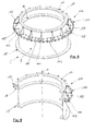
- the foundation fitting 6 according to the FIGS. 8 and 9 corresponds essentially to the foundation fitting 6 according to Fig. 1 and 2 .
- the foundation fitting 6 according to 8 and 9 has a substantially cylindrical or tubular base body 8, on which two annular flanges 16, 18 extend, wherein from the upper annular flange 16 only the inwardly projecting part can be seen.
- a connection flange 10 is further provided, which has a plurality of through holes 11, so that a tower 14 of a wind turbine (see. Fig. 1 ) is attachable to the foundation fitting 6.
- the support sections 114, 116, 118 of the securing bodies 102, 104, 106 each have a receiving device 122 for receiving a support device.
- the receiving device 122 is formed according to this embodiment as a second plurality of through holes.
- the fuse bodies 102, 104, 106 have a plurality of stiffening struts, which are here designed as gusset plates 190 (in FIG 8 and 9 only one provided with reference numerals), whereby a deformation of the fuse body 102, 104, 106 and thus an unwanted "sagging" of the foundation component 6 counteracted. According to this embodiment ( Fig.
- gusset plates 190 are respectively arranged on each securing body 102, 104, 106, so that the securing device 100 has a total of 15 gusset plates 190.
- Fig. 10 For a detailing is on Fig. 10 referred to, which will be described below.
- Fig. 10 is a detail of the upper portion of a foundation component 6 with its connecting flange 10 and upper annular flange 16 and the securing device 100 according to the fourth embodiment shown in a perspective view. Further shows Fig. 10 three gusset plates 190 which extend perpendicular to a flat extension of the fuse body 102 and are arranged thereon. The gusset plates 190 are welded in the web joint by a double fillet 192 on the fuse body 102, 104, 106 attached. The gusset plates 190 each have a contact portion 194, with which they are in contact with the connection flange 10 of the foundation component 6.
- the contact portion 194 further comprises a support means 196, which is formed according to this embodiment as a pressure screw 198 with a ball plate 200.
- a support means 196 which is formed according to this embodiment as a pressure screw 198 with a ball plate 200.
- the pressure screw 198 is screwed through this internal thread in order to realize a non-positive connection between the connection flange 10 and the stiffening strut with the screw base and a suitable ball plate 200.
- the pressure screw 198 is the possibility of realizing an axial bias of the safety body 102, 104, 106 via an adjustment of the inclination of the corresponding node plate 190 to the axis A.
- the support means 196 is substantially is formed according to the support means 124 and insofar reference is made to the above description of the support means 124. Although in this embodiment ( Fig. 8 to 10 Support means 124 are provided on the support portion 114, 116, 118, it should be understood that this is not absolutely necessary, but the support portion 114, 116, 118 also according to the third embodiment ( Fig. 4 ) may be formed.
Abstract
Die Erfindung betrifft Sicherungs-Vorrichtung (100) zum zusätzlichen Sichern eines Fundaments (1), welches ein in einen Betonkörper (2) eingebautes Fundamenteinbauteil (6) zur Aufnahme eines Bauwerks (14), insbesondere eines Turms einer Windenergieanlage aufweist, wobei die Sicherungs-Vorrichtung (100) wenigstens einen Sicherungskörper (102, 104, 106) mit einem Befestigungsabschnitt (108, 110, 112) und einem Stützabschnitt (114, 116, 118) aufweist. Der Befestigungsabschnitt (108, 110, 112) ist erfindungsgemäß zur Befestigung des Sicherungskörpers (102, 104, 106) an dem Fundamenteinbauteil (6) und der Stützabschnitt (114, 116, 118) zum Einleiten von Fundamentkräften in einen vom Fundamenteinbauteil (6) entfernten Abschnitt (23) des Betonkörpers (2) ausgebildet. Die Erfindung betrifft ferner ein Fundament sowie ein Verfahren.The invention relates to a securing device (100) for additionally securing a foundation (1), which has a foundation component (6) installed in a concrete body (2) for receiving a structure (14), in particular a tower of a wind energy plant, wherein the safety Device (100) at least one securing body (102, 104, 106) having a fastening portion (108, 110, 112) and a support portion (114, 116, 118). The attachment portion (108, 110, 112) is according to the invention for attaching the securing body (102, 104, 106) to the foundation fixture (6) and the support portion (114, 116, 118) for introducing foundation forces in one of the foundation fixture (6) Section (23) of the concrete body (2) is formed. The invention further relates to a foundation and a method.
Description
Die Erfindung betrifft eine Sicherungs-Vorrichtung zum zusätzlichen Sichern eines Fundaments, welches ein in einen Betonkörper eingebautes Fundamenteinbauteil zur Aufnahme des Bauwerks, insbesondere eines Turms einer Windenergieanlage (WEA) aufweist. Die Erfindung betrifft ferner ein Fundament für ein solches Bauwerk, insbesondere einen Turm einer Windenergieanlage mit einem Betonkörper und einem in den Betonkörper eingebauten Fundamenteinbauteil, welches einen im Wesentlichen zylindrischen Grundkörper aufweist, an dem sich wenigstens ein Ringflansch erstreckt, der als axiale Verankerung des Fundamenteinbauteils in den Betonkörper dient, wobei das Fundamenteinbauteil mit seiner Zentralachse im Wesentlichen vertikal ausgerichtet eingebaut ist. Weiterhin betrifft die Erfindung ein Verfahren zum Sichern eines Fundaments für ein Bauwerk, insbesondere einen Turm einer Windenergieanlage.The invention relates to a securing device for additionally securing a foundation, which has a built-in concrete body foundation fixture for receiving the structure, in particular a tower of a wind turbine (WEA). The invention further relates to a foundation for such a structure, in particular a tower of a wind turbine with a concrete body and a built-in concrete body foundation fixture, which has a substantially cylindrical body on which extends at least one annular flange, which serves as axial anchoring of the foundation component in the concrete body is used, wherein the foundation component is installed with its central axis substantially vertically aligned. Furthermore, the invention relates to a method for securing a foundation for a building, in particular a tower of a wind turbine.
Der Bedarf an Aufbau von Windenergieanlagen steigt, nicht zuletzt aufgrund der sogenannten Energiewende, stetig. Dabei steigen sowohl die Turmhöhen als auch die Leistung der Windenergieanlagen stetig an, wodurch auch die Anforderungen an Fundamente erhöht werden. Die Fundamente müssen dabei nicht nur das hohe Gewicht aufnehmen, sondern insbesondere auch dynamischen Belastungen standhalten. Der Kraftangriff durch den Wind erfolgt in Nabenhöhe der Windenergieanlage und erzeugt ein Moment am Turmfuß. Dieses Moment muss durch das Fundament aufgenommen werden. Gleichzeitig schwankt dieses Moment mit Rotationen der Turbine, wodurch eine schwingende Belastung in dem Fundament hervorgerufen wird.The demand for the construction of wind turbines is increasing steadily, not least due to the so-called energy transition. Both the tower heights and the performance of the wind turbines are steadily increasing, which also increases the requirements for foundations. The foundations not only have to absorb the heavy weight, but also withstand dynamic loads in particular. The force attack by the wind takes place at the hub height of the wind turbine and generates a moment at the base of the tower. This moment has to be absorbed by the foundation. At the same time, this moment varies with rotations of the turbine, causing a vibratory load in the foundation.
Übliche Fundamente für Windenergieanlagen weisen ein Fundamenteinbauteil auf, welches in einen Betonkörper eingegossen ist. Das Fundamenteinbauteil ist in der Regel aus Stahl gebildet und der Beton ist mittels Stahlbewehrungen verstärkt. Das Fundamenteinbauteil weist in der Regel einen im Wesentlichen zylindrischen oder rohrförmigen Grundkörper auf, an dem sich zwei Ringflansche axial beabstandet voneinander erstrecken. Beide Ringflansche werden in den Betonkörper eingebaut, und zwar so, dass die Zentralachse des zylindrischen Grundkörpers im Wesentlichen vertikal ausgerichtet ist. Ein oberes Ende des Fundamenteinbauteils liegt oberhalb der Oberfläche und weist einen Anschlussflansch auf. An diesen Anschlussflansch wird der Turm der Windenergieanlage angeflanscht. In der Regel wird zwischen den beiden Ringflanschen äußerlich um das Fundamenteinbauteil ein Bewehrungskäfig vorgesehen. Der untere Ringflansch dient dann dazu die auftretenden Momente (insb. auf der windzugewandten Seite) als Druckkräfte nach oben hin in den Betonkörper einzuleiten, und der obere Ringflansch stützt sich von oben auf den darunterliegenden Abschnitt des Betons ab. Eine übliche Belastungssituation ist in
Aufgrund dieses Einbaus und der beschriebenen Belastung ergeben sich verschiedene Probleme. Ein bekanntes Problem, das unmittelbar mit dem Einbau zusammenhängt, liegt im Schrumpfen des Betons beim Abbinden begründet. Jeder Beton unterläuft beim Abbinden einer, wenn auch geringen, Schrumpfung, sodass es in axialer Richtung entlang des Fundamenteinbauteils zwischen den beiden Ringflanschen zu Kammern oder Spalten kommen kann. Hierdurch können sich sowohl der untere Ringflansch nicht mehr ausreichend nach oben hin und der obere Ringflansch nicht mehr ausreichend nach unten abstützen. Hierdurch ist das Fundamenteinbauteil mit einem leichten Spiel ausgestattet, was zu einer Bewegung des gesamten Bauwerks bei Belastung führt.Due to this installation and the described load, various problems arise. A known problem, which is directly related to the installation, is due to the shrinkage of the concrete during setting. Each concrete undergoes a set, albeit small, shrinkage, so that it can come in the axial direction along the foundation fixture between the two annular flanges to chambers or columns. As a result, both the lower annular flange no longer sufficiently upwards and the upper annular flange can no longer sufficiently supported down. As a result, the foundation fixture is equipped with a slight play, resulting in movement of the entire structure under load.
Weitere bekannte Probleme sind Rissbildungen aufgrund von Ermüdung, die teilweise durch fehlerhaften Einbau (Bildung von Kavitäten) oder auch fehlerhafte Ausführung von Betonfugen begünstigt werden.Further known problems are cracking due to fatigue, which is favored in part by faulty installation (formation of cavities) or incorrect execution of concrete joints.
Zur Behebung solcher Fehler, sind bereits verschiedene Konzepte bekannt. Beispielsweise wird von
Ein ähnliches Sanierungskonzept ist von der Firma Vestas Wind System A/S bekannt. Von dieser wird je nach Schadensart ein dreistufiges Verfahren vorgeschlagen. Zunächst werden zum Fundamenteinbauteil schräg verlaufende Injektionsbohrungen sowohl radial außerhalb als auch radial innerhalb des Fundamenteinbauteils vorgesehen, um Beton zum unteren Flansch zu injizieren. Teilweise wird radial außerhalb des oberen Flansches dieser freigelegt, und der Beton vollständig ausgetauscht. Schließlich können zusätzlich am oberen Ringflansch, diesen weiter abstützend, zwischen der unteren Oberfläche des Ringflansches und dem Betonkörper Hydraulikpressen zum Anheben des Turms vorgesehen werden, die aber nur während der Reparaturdauer das Fundamenteinbauteil samt Bauwerk auf Position halten und später nach Verfüllen mit Beton wieder ausgebaut werden. Dies sind jedoch sehr aufwendige Verfahren, die zudem durch das Einbringen der Injektionsbohrungen den Betonkörper zusätzlich schwächen.A similar renovation concept is known by the company Vestas Wind System A / S. From this, a three-stage procedure is proposed depending on the type of damage. First, oblique injection bores are provided to the foundation fixture both radially outwardly and radially within the foundation fixture to inject concrete to the lower flange. Partially, this is exposed radially outside the upper flange, and the concrete is completely replaced. Finally, in addition to the upper annular flange, this further supporting, between the lower surface of the annular flange and the concrete body hydraulic presses are provided for lifting the tower, but keep only during the repair period, the foundation component including building in position and later expanded after backfilling with concrete again , However, these are very complicated procedures, which additionally weaken the concrete body by introducing the injection holes.
Ferner haben alle bekannten Sanierungskonzepte gemein, dass diese erst eingesetzt werden oder eingesetzt werden können, wenn der Schaden bereits eingetreten ist. Prophylaktisch lassen sich diese Konzepte kaum oder gar nicht umsetzen.Furthermore, all known remediation concepts have in common that they can only be used or used when the damage has already occurred. Prophylactically, these concepts can hardly or not at all implement.
Aufgabe der vorliegenden Erfindung ist es daher eine Sicherungs-Vorrichtung, ein Fundament und ein Verfahren der vorgenannten Art anzugeben, die sowohl prophylaktisch als auch zur Sanierung von defekten Fundamenten genutzt werden kann und eine dauerhafte, kostengünstige Lösung zur Sicherung der Sanierung eines Fundaments eines Bauwerks bieten. Dabei soll insbesondere auf zusätzliches Einbringen von Beton oder Betonersatz verzichtet werden.Object of the present invention is therefore to provide a safety device, a foundation and a method of the aforementioned type, which can be used both prophylactically and for the restoration of broken foundations and provide a durable, cost-effective solution for securing the rehabilitation of a foundation of a building , It should be dispensed in particular to additional introduction of concrete or concrete replacement.
Bei einer Sicherungsvorrichtung der eingangs genannten Art zum zusätzlichen Sichern eines Fundaments wird die Aufgabe durch die Merkmale des Anspruchs 1 gelöst, also insbesondere durch wenigstens einen Sicherungskörper mit einem Befestigungsabschnitt und einem Stützabschnitt, wobei der Befestigungsabschnitt zur Befestigung des Sicherungskörpers an dem Fundamenteinbauteil ausgebildet ist und der Stützabschnitt zum Einleiten von Fundamentkräften in einen vom Fundamenteinbauteil entfernten Abschnitt des Betonkörpers ausgebildet ist.In a safety device of the type mentioned for additional securing a foundation, the object is achieved by the features of
Der Erfindung liegt die Erkenntnis zugrunde, dass ein Fundament dadurch zusätzlich gesichert werden kann, indem Fundamentkräfte in durch das Fundamenteinbauteil selbst nicht oder wenig belastete Bereiche eingeleitet werden. Es hat sich gezeigt, dass der Bereich des Betonkörpers am stärksten belastet ist, der sich in axialer Richtung oberbeziehungsweise unterhalb der Ringflansche des Fundamenteinbauteils oder direkt benachbart erstreckt. Bereiche, die entfernt vom Fundamenteinbauteil liegen, sind dagegen oft im Wesentlichen unbelastet. Daher bieten sich solche Abschnitte des Betonkörpers an, um in diese zusätzlich wenigstens einen Teil der Fundamentkräfte einzuleiten.The invention is based on the finding that a foundation can be additionally secured by the fact that foundation forces are introduced into areas that are not or only slightly loaded by the foundation component itself. It has been found that the area of the concrete body is the most heavily loaded, which extends in the axial direction Oberbeziehungsweise below the annular flanges of the foundation component or directly adjacent. In contrast, areas that lie away from the foundation component are often essentially unloaded. Therefore, such sections of the concrete body offer to additionally introduce at least a portion of the foundation forces in this.
Als entfernter Abschnitt des Betonkörpers im Sinne der Erfindung wird ein Abschnitt verstanden, der sich um das Fundamenteinbauteil herum erstreckt, vorzugsweise radial außerhalb, und axial benachbart zu etwaigen Ringflanschen oder anderen am Fundamenteinbauteil vorhandenen Verankerungselementen angeordnet ist. Vorzugsweise ist der entfernte Abschnitt etwa 10 cm bis 80 cm, bevorzugt 30 cm bis 60 cm, besonders bevorzugt etwa 40 cm in radialer Richtung von einem Ringflansch oder einem anderen Verankerungselement des Fundamenteinbauteils entfernt. Bevorzugt ist ein Durchmesser des entfernten Bereichs etwa 1,3 bis 2,5 fach, insbesondere 1,5 bis 2,0 fach, besonders bevorzugt etwa 1,7 fach des Durchmessers des Fundamenteinbauteils. Dieses Maß kann auch abhängig sein von der genauen Dimension einer Bewehrung im Beton, der Stützkräfte aufnehmen soll.As a remote portion of the concrete body according to the invention, a section is understood, which extends around the foundation fitting around, preferably radially outwardly, and axially adjacent to any annular flanges or other anchoring elements present on the foundation fixture. Preferably, the removed portion is about 10 cm to 80 cm, preferably 30 cm to 60 cm, more preferably about 40 cm in the radial direction of an annular flange or other anchoring element of the foundation component. A diameter of the removed region is preferably about 1.3 to 2.5 times, in particular 1.5 to 2.0 times, particularly preferably about 1.7 times the diameter of the foundation component. This dimension may also depend on the exact dimension of a reinforcement in the concrete that is to receive support forces.
Besonders bevorzugt wird die Sicherungsvorrichtung als Sanierungsvorrichtung zum Sanieren eines schadhaften Fundaments eingesetzt. Sind bei einem Fundament bereits die oben beschriebenen Schäden aufgetreten, und haben sich beispielsweise Kavitäten oder Spalten axial benachbart der Ringflansche des Fundamenteinbauteils gebildet, wird die erfindungsgemäße Sicherungsvorrichtung vorzugsweise zum Sanieren eines derartigen Fundaments eingesetzt. Dabei dient der Stützabschnitt bevorzugt zum Einleiten von Fundamentkräften in einen vom Fundamenteinbauteil entfernten Abschnitt des Betonkörpers, der intakt ist. Als intakter Abschnitt des Betonkörpers wird ein Abschnitt verstanden, der noch keine oder keine wesentlichen Ermüdungserscheinungen hat, und in dem keine fehlerhaften Betonfugen oder Risse vorhanden sind.Particularly preferably, the securing device is used as a refurbishment device for refurbishing a damaged foundation. If the above-described damage has already occurred in the case of a foundation and, for example, cavities or gaps have formed axially adjacent to the annular flanges of the foundation component, the securing device according to the invention is preferably used for refurbishing such a foundation. The support section preferably serves for introducing foundation forces into a section of the concrete body which is remote from the foundation component and which is intact. An intact section of the concrete body is understood to mean a section which has no or no significant signs of fatigue and in which no faulty concrete joints or cracks are present.
Die Erfindung ist nicht auf den Einsatz bei Windenergieanlagen beschränkt, auch wenn sie hier besonders vorteilhaft und auf wirtschaftliche Art und Weise eingesetzt werden kann. Vielmehr kann eine erfindungsgemäße Sicherungsvorrichtung zum zusätzlichen Sichern eines Fundaments auch bei ähnlichen Belastungssituationen ähnlichen Fundamenten, die ein in einen Betonkörper eingebautes Fundamenteinbauteil aufweisen, eingesetzt werden. Bauwerke, die an einem solchen Fundamenteinbauteil befestigt werden, umfassen etwa, sind jedoch nicht beschränkt auf, Maschinen, insbesondere Abkantanlagen, Großmaschinen, Pressen, Strommasten, Sendemasten, Brückenpfeiler, Gebäudepfeiler und dergleichen. Besonders vorteilhaft ist der Einsatz der Sicherungsvorrichtung bei dynamisch belasteten Fundamenten. Der Betonkörper ist vorzugsweise als Stahlbetonkörper ausgebildet und dazu ausgelegt, Fundamentkräfte aufzunehmen. Bevorzugt sind auch andere Betonarten, wie etwa Spannbeton, faserverstärkter Beton, Textilbeton, Reaktionsbeton und Ähnliches.The invention is not limited to use in wind turbines, although it can be used here particularly advantageously and economically. Rather, a securing device according to the invention for additional securing a foundation, similar even in similar stress situations Foundations having a built-in concrete body foundation fixture, are used. Structures affixed to such a foundation fixture include, but are not limited to, machinery, in particular folding machines, large machinery, presses, power poles, transmission towers, bridge piers, building piers, and the like. Particularly advantageous is the use of the securing device for dynamically loaded foundations. The concrete body is preferably designed as a reinforced concrete body and adapted to receive foundation forces. Also preferred are other types of concrete, such as prestressed concrete, fiber reinforced concrete, textile concrete, reaction concrete and the like.
In einer ersten bevorzugten Ausführungsform ist ein maximaler Außendurchmesser des Sicherungskörpers größer als ein maximaler Außendurchmesser des Fundamenteinbauteils. Vorzugsweise ist ein maximaler Außendurchmesser des Sicherungskörpers größer als ein maximaler Außendurchmesser eines oberen Ringflansches oder eines anderen Verankerungselement des Fundamenteinbauteils. Vorzugweise ist der maximale Außendurchmesser des Sicherungskörpers um wenigstens 5%, wenigstens 10%, wenigstens 15%, wenigstens 20% größer als der maximale Außendurchmesser des Fundamenteinbauteils.In a first preferred embodiment, a maximum outer diameter of the securing body is greater than a maximum outer diameter of the foundation component. Preferably, a maximum outer diameter of the securing body is greater than a maximum outer diameter of an upper annular flange or another anchoring element of the foundation component. Preferably, the maximum outer diameter of the securing body is at least 5%, at least 10%, at least 15%, at least 20% larger than the maximum outer diameter of the foundation component.
In einer weiteren bevorzugten Ausführungsform ist der Sicherungskörper als Ringsegment ausgebildet, insbesondere als Halb-, Drittel-, oder Viertelringsegment. Diese Ausführungsform ist besonders bevorzugt, wenn das Fundamenteinbauteil eine zylindrische Grundform hat. Bei einem rechteckigen Fundamenteinbauteil sind bevorzugt entsprechend winklige Sicherungskörper vorgesehen. Das Gleiche gilt für Fundamenteinbauteile, die eine Polygongrundform haben, beispielsweise sechseckig oder achteckig, bei denen entsprechend ebenso winklige Sicherungskörper vorgesehen sind. Ist der Sicherungskörper als Ringsegment ausgebildet, ist die Montage wesentlich vereinfacht. Beispielsweise ist der Sicherungskörper als Halbringsegment ausgebildet. Bei einem solchen Fall werden vorzugsweise zwei Sicherungskörper für die erfindungsgemäße Sicherungsvorrichtung verwendet, um gemeinsam einen vollständigen Ring zu bilden, der äußerlich umfänglich an dem Fundamenteinbauteil mittels des Befestigungsabschnitts des Sicherungskörpers befestigt wird.In a further preferred embodiment, the securing body is designed as a ring segment, in particular as a half, third, or quarter ring segment. This embodiment is particularly preferred when the foundation fixture has a cylindrical basic shape. In the case of a rectangular foundation fitting, correspondingly angular securing bodies are preferably provided. The same applies to foundation components, which have a basic polygon shape, such as hexagonal or octagonal, in which also correspondingly angular securing body are provided. If the fuse body is designed as a ring segment, assembly is considerably simplified. For example, the fuse body is designed as a half-ring segment. In such a case, two securing bodies are preferably used for the securing device according to the invention in order to jointly form a complete ring, which is externally peripherally fastened to the foundation component by means of the fastening portion of the securing body.
Bevorzugt ist der Sicherungskörper im Wesentlichen eben ausgebildet. Vorzugsweise ist der Sicherungskörper aus Blech, insbesondere Stahlblech gebildet. Dies ist eine besonders einfache Möglichkeit, den Sicherungskörper herzustellen. Beispielsweise ist ein Stahlblech mit 50 mm Stärke bevorzugt. Dies bietet eine ausreichende Kraft, um Fundamente bei Windenergieanlagen zu sichern. Je nach Größe des Fundaments und des an dem Fundamt befestigten Bauwerks sowie der Art der aufzunehmenden Kräfte, können auch andere Blechstärken bevorzugt sein. Ist der Sicherungskörper im Wesentlichen eben ausgebildet, ist seine Herstellung sowie sein Transport und seine Montage wesentlich vereinfacht. Hierdurch können Kosten, verglichen mit üblichen Sicherungs- beziehungsweise Sanierungskonzepten, reduziert werden.Preferably, the fuse body is substantially planar. Preferably, the fuse body is formed from sheet metal, in particular sheet steel. This is a particularly easy way to make the fuse body. For example, a steel sheet with 50 mm thickness is preferred. This provides sufficient strength to Secure foundations in wind turbines. Depending on the size of the foundation and the structure attached to the lost property as well as the nature of the forces to be absorbed, other sheet thicknesses may also be preferred. If the fuse body is substantially flat, its manufacture, as well as its transport and assembly, are considerably simplified. As a result, costs compared to conventional backup or renovation concepts can be reduced.
In einer bevorzugten Weiterbildung weist der Befestigungsabschnitt eine erste Mehrzahl an Durchgangslöchern zur Aufnahme von Befestigungsmitteln zur Befestigung des Sicherungskörpers an dem Fundamenteinbauteil auf. Bevorzugt sind die Befestigungsmittel als Befestigungsschrauben ausgebildet. Dies ist eine besonders einfache und auch nachträglich ohne großen Aufwand anzubringende Befestigungsmöglichkeit für den Sicherungskörper. Dadurch ist es möglich, an dem Fundamenteinbauteil korrespondierende Befestigungsmittel vorzusehen, insbesondere Gewindebohrungen. Befestigungsschrauben bieten eine gewisse Elastizität, die beim Einleiten von Fundamentkräften mittels des Sicherungskörpers von dem Fundamenteinbauteil in einen von dem Fundamenteinbauteil entfernten Abschnitt des Betonkörpers vorteilhaft wirken. Es kann auch bevorzugt sein, den Sicherungskörper mittels einer Schweißverbindung an dem Fundamenteinbauteil anzubringen, allerdings hat eine Schweißverbindung den Nachteil des Schweißverzugs des Materials, was sich bei dynamischer Belastung nachteilig auswirken kann.In a preferred embodiment, the attachment portion has a first plurality of through holes for receiving fastening means for fastening the securing body to the foundation fixture. Preferably, the fastening means are designed as fastening screws. This is a particularly simple and subsequently without much effort to be attached mounting option for the fuse body. This makes it possible to provide on the foundation fixture corresponding fastening means, in particular threaded holes. Fixing screws provide a degree of elasticity which, upon introduction of foundation forces by means of the securing body, is advantageous from the foundation fitting into a portion of the concrete body remote from the foundation fitting. It may also be preferable to attach the fuse body to the foundation fixture by means of a welded joint, but a welded joint has the disadvantage of weld distortion of the material, which may be detrimental to dynamic loading.
In einer bevorzugten Variante ist vorgesehen, dass an dem Sicherungskörper wenigstens eine Versteifungsstrebe angeordnet ist, die einen Kontaktabschnitt aufweist, der dazu eingerichtet ist mit einem Abschnitt eines Fundamenteinbauteils und/oder einem daran angeordneten Bauwerk in Anlage zu kommen. Durch die Anordnung der Versteifungsstrebe am Sicherungskörper und deren Anlage an einem Abschnitt eines Fundamenteinbauteils und/oder einem daran angeordneten Bauwerk entsteht eine versteifende Wirkung für den Sicherungskörper. Die Versteifungsstrebe ist bevorzugt zum Abstützen des Sicherungskörpers ausgebildet, um eingeleitete Fundamentkräfte wenigstens teilweise aufzunehmen. Die versteifende Wirkung wird durch die Anordnung von mindestens einer Versteifungsstrebe je Sicherungskörper erzielt, die zusätzlich durch die Anlage an einem Fundamenteinbauteil und/oder einem daran angeordneten Bauwerk die Kräfte aufnimmt. Es kann ein ungewolltes "hochbiegen" des Sicherungskörpers vermieden werden. Bevorzugt kommt der Kontaktabschnitt mit einem äußeren Umfang eines Flansches, etwa einem Anschlussflansch des Fundamenteinbauteils in Anlage. Ein solcher Flanschabschnitt ist aufgrund seiner radialen Ausdehnung besonders zur Abstützung und Aufnahme von Kräften geeignet. Vorzugsweise sind dabei zwei oder mehr, insbesondere fünf oder mehr Versteifungsstreben an einem Sicherungskörper angeordnet. Es ist bevorzugt die Versteifungsstreben so vorzusehen, dass sie einen im Wesentlichen gleichen Abstand zu einander haben. Bevorzugt erstreckt sich die Versteifungsstrebe in einem eingebauten Zustand im Wesentlichen vertikal nach oben von dem Sicherungskörper.In a preferred variant it is provided that at least one stiffening strut is arranged on the securing body, which has a contact portion which is adapted to come into contact with a section of a foundation fixture and / or a structure arranged thereon. The arrangement of the stiffening strut on the fuse body and its contact with a portion of a foundation component and / or a building arranged thereon creates a stiffening effect for the fuse body. The stiffening strut is preferably designed to support the securing body in order to at least partially accommodate introduced foundation forces. The stiffening effect is achieved by the arrangement of at least one stiffening strut per fuse body, which additionally absorbs the forces by the system on a foundation fixture and / or a structure arranged thereon. It can be avoided accidental "bending up" of the fuse body. The contact section preferably comes into contact with an outer circumference of a flange, for example a connection flange of the foundation component. Such a flange portion is due to its radial extent particularly for Support and absorption of forces suitable. Preferably, two or more, in particular five or more stiffening struts are arranged on a securing body. It is preferred to provide the stiffening struts so as to be substantially equidistant from each other. Preferably, the stiffening strut extends in an installed state substantially vertically upward from the fuse body.
In einer weiteren bevorzugten Ausführungsform ist die Versteifungstrebe als Knotenblech ausgebildet, welches sich im Wesentlichen senkrecht zu einer flächigen Ausdehnung des Sicherungskörpers erstreckt. Das Knotenblech ist am Sicherungskörper fixiert, vorzugsweise durch eine stoffschlüssige Verbindung, beispielsweise eine Schweißverbindung. Das Knotenblech ist vornehmlich aus Stahl bevorzugt aus einem Stahlblech gebildet. Die Flächen des Knotenblechs können als geschlossene oder wenigstens teilweise offene Flächen mit Ausnehmungen und/oder Durchbrüchen gestaltet sein. Teilweise offene Flächen haben den Vorteil eines geringeren Gewichts und Materialeinsparung.In a further preferred embodiment, the stiffening strut is designed as a gusset plate, which extends substantially perpendicular to a planar extension of the securing body. The gusset plate is fixed to the fuse body, preferably by a cohesive connection, such as a welded joint. The gusset plate is preferably made of steel, preferably formed from a steel sheet. The surfaces of the gusset plate can be designed as closed or at least partially open surfaces with recesses and / or openings. Partially open areas have the advantage of lower weight and material savings.
In einer weiteren besonders bevorzugten Ausführungsform ist vorgesehen, dass der Stützabschnitt des Sicherungskörpers wenigstens eine Aufnahmeeinrichtung für eine Stützeinrichtung aufweist. Die Stützeinrichtung ist vorzugsweise zum Abstützen des Sicherungskörpers auf dem entfernten Abschnitt des Betonkörpers und zum Vorspannen des Sicherungskörpers in eine vertikale Richtung ausgebildet. Die Stützeinrichtung kann einteilig an dem Stützabschnitt des Sicherungskörpers vorgesehen sein, oder reversibel lösbar mit diesem verbunden sein. Mittels der Stützeinrichtung ist eine besonders bevorzugte Kopplung des Stützabschnitts mit dem Betonkörper erreicht. Ferner lässt sich mittels der Stützeinrichtung eine gezielte Vorspannung des Stützabschnitts in vertikale Richtung, das heißt eine Zugkraft auf das Fundamenteinbauteil vertikal nach oben, also aus dem Betonkörper heraus, erreichen. Dies ist bevorzugt, um einen unteren Ringflansch oder anderes unteres Verankerungselement, mit seiner axial nach oben gerichteten Oberfläche gegen einen Abschnitt des Betonkörpers zu pressen, um so Spiel zu verringern und eine Krafteinleitung in den Betonkörper zu erreichen, bei gleichzeitiger Verringerung einer Bewegbarkeit des Fundamenteinbauteils relativ zum Betonkörper. Hierdurch ist die Sicherheit des Fundaments insgesamt verbessert, und eine dauerhafte Befestigung erreicht.In a further particularly preferred embodiment it is provided that the support portion of the fuse body has at least one receiving device for a support device. The support means is preferably for supporting the securing body on the removed portion of the concrete body and for biasing the securing body in a vertical direction. The support means may be integrally provided on the support portion of the fuse body, or be reversibly detachably connected thereto. By means of the support means a particularly preferred coupling of the support portion is achieved with the concrete body. Furthermore, by means of the support means, a targeted bias of the support portion in the vertical direction, that is, a tensile force on the foundation component vertically upwards, ie out of the concrete body, reach. This is preferred to press a lower annular flange or other lower anchoring element with its axially upwardly facing surface against a portion of the concrete body so as to reduce backlash and achieve force introduction into the concrete body, while reducing movability of the foundation fixture relative to the concrete body. As a result, the safety of the foundation is improved overall, and achieved a permanent attachment.
In einer bevorzugten Weiterbildung weist die Aufnahmeeinrichtung für die Stützeinrichtung eine zweite Mehrzahl an Durchgangslöchern auf. Die zweite MehrzahlIn a preferred development, the receiving device for the support device on a second plurality of through holes. The second plurality
Durchgangslöcher dient insbesondere dazu, die Stützeinrichtung wenigstens teilweise aufzunehmen, um so eine kraft- und/oder formschlüssige Verbindung zwischen der Stützeinrichtung und dem Stützabschnitt des Sicherungskörpers herzustellen.Through holes serve in particular to at least partially receive the support means, so as to produce a non-positive and / or positive connection between the support means and the support portion of the fuse body.
Weiterhin ist bevorzugt, dass bei einer oben beschriebenen Sicherungsvorrichtung mit wenigstens einer Versteifungsstrebe der Kontaktabschnitt eine Stützeinrichtung aufweist. Die Stützeinrichtung an dem Kontaktabschnitt der Versteifungsstrebe und die Stützeinrichtung, die an der Aufnahmeeinrichtung des Stützkörpers angeordnet ist, können identisch oder ähnlich sein und insbesondere gemäß einem der nachfolgenden Aspekte ausgebildet sein.Furthermore, it is preferred that in a safety device described above with at least one stiffening strut, the contact portion has a support means. The support means on the contact portion of the stiffening strut and the support means, which is arranged on the receiving device of the support body, may be identical or similar and in particular be designed according to one of the following aspects.
In einer bevorzugten Variante weist die Stützeinrichtung wenigstens eine Druckschraube mit einem Kugelteller auf. Vorzugsweise sind dabei die Durchgangslöcher der Aufnahmeeinrichtung mit Innengewinden versehen, um die Druckschraube aufzunehmen. Der Kugelteller der Druckschraube stützt sich bevorzugt direkt auf dem Betonkörper ab. Um eine Flächenpressung zu reduzieren, kann vorgesehen sein, dass zwischen dem Kugelteller und dem Betonkörper ein oder mehrere zusätzliche Druckstücke vorgesehen sind. Derartige Druckstücke können beispielsweise als Metallblech, insbesondere Stahlblech oder dergleichen, ausgebildet sein und dienen dazu, die Flächenpressung zu reduzieren, um so eine Beschädigung des Betonkörpers weitestgehend zu vermeiden. Durch den Kugelteller ist stets eine plane Auflage auf dem Betonkörper oder dem Druckstück erreicht. Ein Kugelteller kann gewisse Neigungen ausgleichen, was insbesondere bei einer dynamischen Belastung des Fundaments vorteilhaft ist.In a preferred variant, the support device has at least one pressure screw with a ball plate. Preferably, the through holes of the receiving device are provided with internal threads to receive the pressure screw. The ball plate of the pressure screw is preferably supported directly on the concrete body. In order to reduce a surface pressure, it can be provided that one or more additional pressure pieces are provided between the ball plate and the concrete body. Such pressure pieces may be formed, for example, as a metal sheet, in particular steel sheet or the like, and serve to reduce the surface pressure, so as to avoid damage to the concrete body as far as possible. Through the ball plate is always a flat support on the concrete body or the pressure piece achieved. A ball plate can compensate for certain inclinations, which is particularly advantageous for a dynamic load on the foundation.
Zusätzlich oder alternativ weist die Stützeinrichtung wenigstens einen Hartgummikörper auf. Ein solcher Hartgummikörper erstreckt sich vorzugsweise flächig entlang des gesamten Stützabschnitts des Sicherungskörpers. Der Hartgummikörper ist dazu eingerichtet, auf dem Betonkörper in dem vom Fundamenteinbauteil entfernten Abschnitt aufzuliegen. Eine axiale Dicke des Hartgummikörpers kann so gewählt sein, dass das Fundamenteinbauteil in vertikale Richtung nach oben belastet wird und so ein unterer Ringflansch oder ein distal unterhalb des Erdbodens in dem Betonkörper angeordnetes Verankerungselement mit seiner nach oben gerichteten Oberfläche gegen einen Abschnitt des Betonkörpers gepresst wird. Ein Hartgummikörper hat ferner den Vorteil, dass er aufgrund der Elastizität geringe Bewegungen zulässt und gleichzeitig schwingungsdämpfend wirkt. Es wird eine zu große Flächenpressung am Betonkörper vermieden, und gleichzeitig kann eine Abdichtung gegen Wassereintritt realisiert werden. Ferner ist ein Hartgummikörper ein kostengünstiges Bauteil, wodurch sich die Sicherungsvorrichtung insgesamt kostengünstig herstellen lässt.Additionally or alternatively, the support means comprises at least one hard rubber body. Such a hard rubber body preferably extends flat over the entire support portion of the fuse body. The hard rubber body is adapted to rest on the concrete body in the portion remote from the foundation fixture. An axial thickness of the hard rubber body may be selected to load the foundation fixture in a vertical upward direction, thereby pressing a lower annular flange or an anchoring element located distally beneath the ground in the concrete body with its upwardly directed surface against a portion of the concrete body. A hard rubber body also has the advantage that it allows low movements due to the elasticity and at the same time has a vibration-damping effect. It is avoided too large surface pressure on the concrete body, and at the same time a seal against water ingress can be realized. Further, a hard rubber body is a low-cost component, whereby the securing device can be produced overall cost.
Weiterhin ist bevorzugt, dass die Stützeinrichtung alternativ oder zusätzlich wenigstens ein Federelement, insbesondere eine Tellerfeder, aufweist. Vorzugsweise weist die Stützeinrichtung eine Mehrzahl an Tellerfedern auf. Mittels Tellerfedern ist auf besonders einfache und kostengünstige Weise eine Vorspannung in vertikale Richtung des Sicherungskörpers und somit des Fundamenteinbauteils erreichbar.Furthermore, it is preferred that the support means alternatively or additionally comprises at least one spring element, in particular a plate spring. Preferably, the support means comprises a plurality of disc springs. By means of disc springs in a particularly simple and cost-effective manner, a bias in the vertical direction of the fuse body and thus the foundation fixture can be achieved.
Bevorzugt ist darüberhinaus, dass die Stützeinrichtung zusätzlich oder alternativ wenigstens einen Hydraulikzylinder aufweist. Vorzugsweise weist die Stützeinrichtung eine Mehrzahl an Hydraulikzylindern auf. Mittels Hydraulikzylindern ist eine Vorspannung in vertikale Richtung besonders gut einstellbar. Eine Hydraulikversorgung für die Hydraulikzylinder kann beispielsweise im Inneren des Turmschafts der Windenergieanlage untergebracht werden. Mittels Hydraulikzylindern kann auch eine nachträgliche Nachstellung der Vorspannung bei Auftreten von Setzungserscheinungen oder dergleichen vorgesehen werden.In addition, it is preferred that the support device additionally or alternatively has at least one hydraulic cylinder. Preferably, the support means comprises a plurality of hydraulic cylinders. By means of hydraulic cylinders, a bias in the vertical direction is particularly easy to adjust. A hydraulic supply for the hydraulic cylinders can be accommodated, for example, inside the tower shaft of the wind energy plant. By means of hydraulic cylinders can also be provided a subsequent adjustment of the bias voltage at the onset of subsidence or the like.
Bevorzugt ist ferner, dass die Stützeinrichtung zusätzlich oder alternativ einen Schwingungsdämpfer aufweist. Als Schwingungsdämpfer können beispielsweise solche eingesetzt werden, die unter der Marke Schwingmetall® von der Firma ContiTech AG, Hannover, erhältlich sind. Solche Schwingungsdämpfer lassen sich auf einfache Art und Weise mit dem Stützabschnitt des Sicherungskörpers mittels einer Schraubverbindung verbinden, sind preiswert und für solche Belastungen ausgelegt.It is further preferred that the support means additionally or alternatively comprises a vibration damper. As vibration damper, for example, those can be used which are available under the brand Schwingmetall® from the company ContiTech AG, Hannover. Such vibration dampers can be connected in a simple manner with the support portion of the fuse body by means of a screw connection, are inexpensive and designed for such loads.
In einer bevorzugten Weiterbildung weist die Stützeinrichtung zusätzlich oder alternativ wenigstens einen Maschinenfuß auf. Auch Maschinenfüße sind für solche Belastungen ausgelegt und haben zudem dämpfende Eigenschaften. Sie lassen sich auf vorteilhafte Weise im Stützabschnitt anordnen, um eine Anbindung des Sicherungskörpers an den Betonkörper zu erreichen.In a preferred development, the support means additionally or alternatively on at least one machine base. Also machine feet are designed for such loads and also have damping properties. They can be arranged in an advantageous manner in the support section in order to achieve a connection of the fuse body to the concrete body.
In einer weiteren bevorzugten Ausgestaltung weist die Stützeinrichtung zusätzlich oder alternativ wenigstens ein Spannkeilpaar auf. Ein solches Spannkeilpaar besteht vorzugsweise aus zwei Spannkeilen, die im Querschnitt eine Form haben, die einem rechtwinkligen Dreieck entspricht, und mit Ihren Seiten, die die Hypotenuse definieren, aneinander anliegen. Mittels einer Spanneinrichtung, beispielsweise einer Spannschraube, sind die beiden Spannkeile gegeneinander verspannbar und verschiebbar, sodass zwei Seitenflächen des Spannkeilpaars, die sich im Wesentlichen parallel zur Spannrichtung erstrecken, voneinander weg bewegbar sind. Wird das Spannkeilpaar so an dem Sicherungskörper vorgesehen, dass eine der Oberflächen mit dem Stützabschnitt zusammenwirkt und die andere Oberfläche an dem Betonkörper anliegt, kann mittels der Spannkeile eine Presskraft aufgebracht werden, um so das Fundamenteinbauteil in eine vertikale Richtung zu belasten. Dies ist eine maschinenbaulich einfache Lösung, die ebenfalls eine Nachstellung beziehungsweise Nachjustierung ermöglicht und zudem eine kostengünstige Alternative zu Hydraulikzylindern bietet.In a further preferred embodiment, the support means additionally or alternatively on at least one clamping wedge pair. Such a pair of clamping wedges preferably consists of two clamping wedges which, in cross-section, have a shape which corresponds to a right-angled triangle and abut one another with their sides which define the hypotenuse. By means of a clamping device, such as a clamping screw, the two clamping wedges are braced against each other and displaceable, so that two side surfaces of the clamping wedge pair, which extend substantially parallel to the clamping direction, are movable away from each other. If the clamping wedge pair is provided on the securing body such that one of the surfaces cooperates with the supporting portion and the other surface bears against the concrete body, a pressing force can be applied by means of the clamping wedges so as to load the foundation fitting in a vertical direction. This is a machine-technically simple solution, which also allows readjustment or readjustment and also offers a cost-effective alternative to hydraulic cylinders.
In einer alternativen Weiterbildung ist der Stützabschnitt des Sicherungskörpers dazu ausgebildet, unmittelbar auf dem vom Fundamenteinbauteil entfernten Abschnitt des Betonkörpers aufzuliegen. Unmittelbar bedeutet hier, dass kein weiteres Zwischenelement wie eine Stützeinrichtung, vorgesehen ist. Der Sicherungskörper liegt mit seinem Stützabschnitt direkt auf dem Betonkörper auf, wobei in Kauf genommen wird, dass Verunreinigungen oder Elemente einer Oberflächenvorbehandlung, wie beispielsweise Vergussmasse, an dem Betonkörper vorhanden sind. Je nach Einsatzfall ist auch eine solche Ausgestaltung der Sicherungsvorrichtung bevorzugt und besonders kostengünstig umsetzbar.In an alternative development, the support section of the securing body is designed to rest directly on the section of the concrete body remote from the foundation fixture. Immediately here means that no further intermediate element such as a support device is provided. The securing body lies with its support portion directly on the concrete body, it being accepted that impurities or elements of a surface pretreatment, such as potting compound, are present on the concrete body. Depending on the application and such an embodiment of the securing device is preferred and particularly inexpensive to implement.
Die eingangs genannte Aufgabe wird in einem weiteren Aspekt der Erfindung bei einem Fundament der eingangs genannten Art gelöst durch eine Sanierungsvorrichtung mit den Merkmalen wenigstens einer der vorstehend beschriebenen bevorzugten Ausführungsformen einer Sicherungsvorrichtung gemäß dem ersten Aspekt der Erfindung. Bezüglich der Vorteile und bevorzugten Ausführungsformen wird vollumfänglich auf die obige Beschreibung Bezug genommen.The above object is achieved in a further aspect of the invention in a foundation of the type mentioned by a remediation device having the features of at least one of the above-described preferred embodiments of a securing device according to the first aspect of the invention. With regard to the advantages and preferred embodiments, reference is made in full to the above description.
Vorzugsweise weist das Fundamenteinbauteil wenigstens zwei axial beabstandet voneinander angeordnete Ringflansche auf. Vorzugsweise weist der Betonkörper ferner eine Stahlbewehrung auf, wenigstens axial zwischen den beiden Ringflanschen. Dadurch wird eine gute Verankerung erreicht. Anstelle von Ringflanschen können auch andere Verankerungselemente vorgesehen sein, beispielsweise unterbrochene Flansche, die ebenfalls unter den Begriff des Ringflansches gefasst werden.The foundation component preferably has at least two annular flanges arranged axially spaced from one another. Preferably, the concrete body further comprises a steel reinforcement, at least axially between the two annular flanges. This achieves a good anchoring. Instead of annular flanges and other anchoring elements may be provided, for example, interrupted flanges, which are also taken under the concept of the annular flange.
In einer ersten bevorzugten Ausführungsform des Fundaments weist das Fundamenteinbauteil axial beabstandet wenigstens zwei Ringflansche an dem Grundkörper auf, und der Sicherungskörper ist an dem oberen der beiden Ringflansche befestigt. Hierdurch wird eine besonders gute Sicherung des Fundaments erreicht. Der obere Ringflansch des Fundamenteinbauteils wird im Wesentlichen von seiner nach unten gerichteten Oberfläche aus belastet. Er ist in der Regel oberflächennah angeordnet und nur mit einer vergleichsweise dünnen Betonschicht bedeckt, die zudem in der Regel keine Bewehrung aufweist. Der untere Ringflansch hingegen ist unterhalb des Erdbodens in dem Betonkörper eingegossen und etwa 1 bis 2 Meter von dem oberen Ringflansch beabstandet. Der untere Ringflansch wird im Wesentlichen von seiner oberen Oberfläche aus belastet. Über der oberen Oberfläche des unteren Ringflansches ist in der Regel eine Bewehrung angeordnet. Aus diesem Grund ist es wesentlich einfacher, den Sicherungskörper am oberen Ringflansch zu befestigen. Andererseits ist eine Befestigung des Sicherungskörpers am oberen Ringflansch auch auf einfachere Art und Weise zu belasten, nämlich indem sich dieser mit dem Stützabschnitt auf einer Oberfläche des Betonkörpers abstützt. Ein Einbau des Sicherungskörpers in den Betonkörper ist nicht erforderlich. Es kann eine zusätzliche Abdeckung, insbesondere zum Schutz der Verbindung zwischen dem Fundamenteinbauteil und dem Sicherungskörper, vorgesehen sein, dies ist jedoch nicht zwingend erforderlich.In a first preferred embodiment of the foundation, the foundation member axially spaced at least two annular flanges on the base body, and the securing body is at the upper of the two annular flanges attached. As a result, a particularly good backup of the foundation is achieved. The upper annular flange of the foundation fixture is substantially loaded from its downwardly facing surface. It is usually arranged close to the surface and covered only with a comparatively thin layer of concrete, which also generally has no reinforcement. The lower annular flange, however, is poured below the ground in the concrete body and spaced about 1 to 2 meters from the upper ring flange. The lower annular flange is loaded substantially from its upper surface. Over the upper surface of the lower ring flange a reinforcement is usually arranged. For this reason, it is much easier to attach the fuse body to the upper ring flange. On the other hand, a fastening of the securing body to the upper annular flange is also to be loaded in a simpler manner, namely by being supported by the supporting section on a surface of the concrete body. An installation of the fuse body in the concrete body is not required. It may be an additional cover, in particular to protect the connection between the foundation component and the fuse body, be provided, but this is not mandatory.
Gemäß einer weiteren bevorzugten Ausführungsform des Fundaments weist der obere Ringflansch eine Mehrzahl an Gewindebohrungen zur Aufnahme von Befestigungsschrauben auf. Mittels dieser Gewindebohrungen ist der Sicherungskörper über den Befestigungsabschnitt an dem Fundamenteinbauteil befestigbar. Bevorzugt sind insbesondere Sacklochbohrungen, da diese einen gewissen Schutz gegen eindringendes Wasser bieten können und so zu einer dauerhaften Lösung beitragen. Weiterhin sind Sacklochbohrungen einfacher einzubringen als Durchgangsbohrungen, da weniger Material zerspant werden muss und sonst die Gefahr besteht, dass das genutzte Bohrwerk vom darunterliegenden Beton beschädigt wird.According to a further preferred embodiment of the foundation, the upper annular flange has a plurality of threaded bores for receiving fastening screws. By means of these threaded holes of the fuse body can be fastened via the attachment portion to the foundation fixture. Blind holes are particularly preferred because they can provide some protection against water penetration and thus contribute to a permanent solution. Furthermore, blind holes are easier to insert than through holes, as less material must be machined and otherwise there is a risk that the used boring machine is damaged by the underlying concrete.
Gemäß einer bevorzugten Ausgestaltung des Fundaments ist zwischen dem Stützabschnitt und dem Betonkörper wenigstens ein Druckstück zur Übertragung von Fundamentkräften von dem Stützabschnitt in den Betonkörper vorgesehen. Ein solches Druckstück ist vorzugsweise als Metallplatte, insbesondere Stahlplatte ausgebildet, um eine Flächenpressung zwischen dem Stützabschnitt und dem Betonkörper zu vermeiden oder zu verringern.According to a preferred embodiment of the foundation, at least one thrust piece for transmitting foundation forces from the support portion into the concrete body is provided between the support portion and the concrete body. Such a pressure piece is preferably formed as a metal plate, in particular steel plate, to avoid or reduce a surface pressure between the support portion and the concrete body.
Bevorzugt ist das Druckstück mittels einer Vergussmasse im Wesentlichen horizontal ausgerichtet an dem Betonkörper in dem vom Fundamenteinbauteil entfernten Abschnitt des Betonkörpers befestigt. Als Vergussmasse kann jegliche Art geeigneter Vergussmasse, wie etwa ein Harz, eingesetzt werden. Hierdurch lässt sich eine vorteilhafte Einleitung von Stützkräften in den Betonkörper bewirken.Preferably, the pressure piece is fastened by means of a potting compound substantially horizontally aligned to the concrete body in the portion of the concrete body remote from the foundation fixture. As casting compound can be any kind of suitable Potting compound, such as a resin used. This can cause an advantageous introduction of supporting forces in the concrete body.
Gemäß einem dritten Aspekt der Erfindung wird die eingangs genannte Aufgabe bei einem Verfahren der eingangs genannten Art zum Sichern eines Fundaments für ein Bauwerk, insbesondere einen Turm einer Windenergieanlage, mit einem Betonkörper und einem in dem Betonkörper eingebauten Fundamenteinbauteil, welches einen Grundkörper aufweist, an dem sich wenigstens ein Ringflansch erstreckt, der als axiale Verankerung des Fundamenteinbauteils in dem Betonkörper dient, und das Fundamenteinbauteil mit seiner Zentralachse im Wesentlichen vertikal ausgerichtet eingebaut ist, gelöst durch den Schritt: Abstützen des Fundamenteinbauteils auf einem vom Fundamenteinbauteil entfernten Abschnitt des Betonkörpers. Der Grundkörper ist vorzugsweise im Wesentlichen zylindrisch ausgebildet.According to a third aspect of the invention, the object mentioned at the outset in a method of the type mentioned above for securing a foundation for a building, in particular a tower of a wind turbine, with a concrete body and a built-in concrete body foundation fixture, which has a base body to which extending at least one annular flange, which serves as an axial anchoring of the foundation component in the concrete body, and the foundation fixture is installed with its central axis substantially vertically aligned, solved by the step: supporting the foundation fixture on a remote from the foundation fixture portion of the concrete body. The main body is preferably formed substantially cylindrical.
Es soll verstanden werden, dass die Sicherungsvorrichtung gemäß dem ersten Aspekt der Erfindung sowie das Fundament gemäß dem zweiten Aspekt der Erfindung und das Verfahren gemäß dem dritten Aspekt der Erfindung eine Vielzahl von gemeinsamen Aspekten und bevorzugten Ausführungsformen aufweisen, wie sie insbesondere in den Unteransprüchen niedergelegt sind. Insofern wird vollumfänglich auf die obige Beschreibung und die darin dargestellten Vorteile verwiesen. Indem das Fundamenteinbauteil zusätzlich auf einem vom Fundamenteinbauteil entfernten Abschnitt des Betonkörpers abgestützt wird, wird eine verbesserte Sicherung erreicht und eine dauerhafte Haltbarkeit des Fundaments erzielt. Der Begriff "entfernter Abschnitt" wird wie oben definiert verstanden.It should be understood that the securing device according to the first aspect of the invention as well as the foundation according to the second aspect of the invention and the method according to the third aspect of the invention have a plurality of common aspects and preferred embodiments as set forth in particular in the subclaims , In this respect, reference is made in full to the above description and the advantages presented therein. In addition, by supporting the foundation fixture on a portion of the concrete body remote from the foundation fixture, improved securement is achieved and lasting durability of the foundation is achieved. The term "removed portion" is understood as defined above.
Besonders bevorzugt ist das Verfahren als Sanierungs-Verfahren zum Sanieren eines schadhaften Fundaments ausgebildet. Weist das Fundament Schäden, wie eingangs erläutert aus, sind diese Schäden mittels des erfindungsgemäßen Verfahrens auf vorteilhafte Weise behebbar. Ein Einbringen von zusätzlichem Beton oder Betonersatz zum Schließen von Rissen oder Hohlräumen ist nicht erforderlich, die notwendige Stabilität wird mittels des Abstützens des Fundamenteinbauteils auf dem vom Fundamenteinbauteil entfernten Abschnitt des Betonkörpers erreicht. Hierdurch ist eine Sanierung wesentlich vereinfacht und ohne großen Aufwand nachträglich durchführbar.The method is particularly preferably designed as a refurbishment method for refurbishing a defective foundation. If the foundation has damage, as explained at the outset, these damages can be advantageously remedied by means of the method according to the invention. It is not necessary to introduce additional concrete or concrete substitutes for closing cracks or cavities; the necessary stability is achieved by supporting the foundation component on the section of the concrete body remote from the foundation component. As a result, a refurbishment is much easier and subsequently feasible without much effort.
Gemäß einem ersten bevorzugten Ausführungsbeispiel des Verfahrens weist dieses den Schritt auf: Befestigen einer Sicherungsvorrichtung nach einer der vorstehend beschriebenen bevorzugten Ausführungsformen einer Sicherungsvorrichtung gemäß dem ersten Aspekt der Erfindung. Die Sicherungsvorrichtung wird vorzugsweise an dem oberen Ringflansch des Fundamenteinbauteils befestigt. Der Schritt des Abstützens des Fundamenteinbauteils auf einem vom Fundamenteinbauteil entfernten Abschnitt des Betonkörpers wird vorzugsweise mittels der Sicherungsvorrichtung gemäß dem ersten Aspekt der Erfindung bewirkt.According to a first preferred embodiment of the method, the method comprises the step of fastening a securing device according to one of the above-described preferred embodiments of a securing device according to the invention first aspect of the invention. The securing device is preferably fastened to the upper annular flange of the foundation component. The step of supporting the foundation fixture on a portion of the concrete body remote from the foundation fixture is preferably effected by means of the fixture according to the first aspect of the invention.
In einer weiteren bevorzugten Ausführungsform des Verfahrens, wobei sich axial beabstandet wenigstens zwei Ringflansche an dem Grundkörper erstrecken, weist das Verfahren den Schritt auf: Pressen der oberen Oberfläche des unteren Ringflansches gegen einen Abschnitt des Betonkörpers. Hierdurch wird eine besonders gute Sicherung des Fundaments erreicht und ein stetiger Kontakt zwischen der oberen Oberfläche des unteren Ringflansches und dem Betonkörper bewirkt. Dies führt zu einer guten Krafteinleitung in den Betonkörper, und eine Bewegung des Fundamenteinbauteils relativ zum Betonkörper wird vermieden. Vorzugsweise wird dieser Schritt mittels der oben beschriebenen Stützeinrichtung bewirkt. Es ist demnach zum Anheben des Fundamenteinbauteils nicht mehr erforderlich zusätzlichen (expandierenden) Beton oder Betonersatz über Bohrungen unter den unteren Ringflansch zu injizieren, vielmehr wird das Fundamenteinbauteil "von oben" mittels der erfindungsgemäßen Sicherungsvorrichtung angehoben und so der Kontakt zwischen dem unteren Ringflansch und dem Betonkörper (wieder) hergestellt.In a further preferred embodiment of the method, wherein at least two annular flanges extend axially spaced from the main body, the method comprises the step of: pressing the upper surface of the lower annular flange against a portion of the concrete body. As a result, a particularly good securing of the foundation is achieved and causes a continuous contact between the upper surface of the lower annular flange and the concrete body. This leads to a good introduction of force into the concrete body, and a movement of the foundation component relative to the concrete body is avoided. Preferably, this step is effected by means of the support means described above. It is therefore no longer necessary to raise the foundation component additional (expanding) concrete or concrete replacement via holes under the lower annular flange, but the foundation component is raised "from above" by means of the securing device according to the invention and so the contact between the lower annular flange and the concrete body (re) produced.
Gemäß einer weiteren bevorzugten Ausführungsform des Verfahrens weist dieses den Schritt auf: Verspannen des Fundamenteinbauteils in vertikale Richtung nach oben. Auch hierdurch wird eine besonders gute Sicherung erreicht, und eventuelle Kavitäten oder Spalten oberhalb des unteren Ringflansches verringert. Zudem wird die Belastung der Ringflansche oder anderer Verankerungselemente wenigstens teilweise verringert.According to a further preferred embodiment of the method, this has the step: clamping the foundation component in a vertical upward direction. This also ensures a particularly good assurance, and reduces any cavities or gaps above the lower annular flange. In addition, the load on the annular flanges or other anchoring elements is at least partially reduced.
Weiterhin ist bevorzugt, dass das Verfahren wenigstens einen der folgenden Schritte aufweist: Freilegen einer oberen Oberfläche des oberen Ringflansches; Einbringen einer Mehrzahl an Gewindebohrungen in die obere Oberfläche des oberen Ringflansches; Drücken mittels einer Stützeinrichtung gegen den Stützabschnitt zum Verspannen des Fundamenteinbauteils; Anordnen wenigstens eines Druckstücks auf eine Oberfläche des vom Fundamenteinbauteil entfernten Abschnitts des Betonkörpers.It is further preferred that the method comprises at least one of the following steps: exposing an upper surface of the upper annular flange; Inserting a plurality of threaded holes in the upper surface of the upper annular flange; Pressing by means of a support device against the support portion for bracing the foundation component; Arranging at least one pressure piece on a surface of the portion of the concrete body remote from the foundation component.
Nachfolgend wird die Erfindung unter Bezugnahme auf die beiliegenden Figuren genauer beschrieben werden. Dabei zeigen:
- Fig. 1
- einen schematischen Querschnitt durch ein Fundament mit einem darin angeordneten Turm einer Windenergieanlage gemäß Stand der Technik mit typischen Defekten;
- Fig. 2
- eine perspektivische Ansicht eines Fundamenteinbauteils samt Sicherungsvorrichtung gemäß einem ersten Ausführungsbeispiel der Erfindung;
- Fig.3 3
- eine Draufsicht auf einen Sicherungskörper gemäß dem ersten Ausführungsbeispiel der Erfindung;
- Fig.4
- ein Detail der Schnittdarstellung eines Fundamenteinbauteils mit daran angeordneter Sicherungsvorrichtung gemäß dem ersten Ausführungsbeispiel;
- Fig.5
- eine Schnittdarstellung durch ein Fundamenteinbauteil mit einer daran angeordneten Sicherungsvorrichtung gemäß einem zweiten Ausführungsbeispiel;
- Fig. 6
- eine Schnittdarstellung eines Fundamenteinbauteils mit daran angeordneter Sicherungsvorrichtung gemäß einem dritten Ausführungsbeispiel;
- Fig. 7
- eine Schnittdarstellung eines Fundamenteinbauteils mit daran angeordneter Sicherungsvorrichtung und eingezeichneten Anpresskräften;
- Fig. 8
- eine perspektivische Ansicht eines Fundamenteinbauteils mit einer daran angeordneten Sicherungsvorrichtung gemäß einem vierten Ausführungsbeispiel;
- Fig. 9
- eine perspektivische Schnittdarstellung des Fundamenteinbauteils samt Sicherungsvorrichtung aus
Figur 8 ; und - Fig. 10
- ein Detail aus
Figur 9 .
- Fig. 1
- a schematic cross section through a foundation with a tower arranged therein a wind turbine of the prior art with typical defects;
- Fig. 2
- a perspective view of a foundation component including securing device according to a first embodiment of the invention;
- 3
- a plan view of a fuse body according to the first embodiment of the invention;
- Figure 4
- a detail of the sectional view of a foundation component with arranged thereon safety device according to the first embodiment;
- Figure 5
- a sectional view through a foundation fixture with a securing device arranged thereon according to a second embodiment;
- Fig. 6
- a sectional view of a foundation fixture with arranged thereon securing device according to a third embodiment;
- Fig. 7
- a sectional view of a foundation component with arranged thereon securing device and indicated contact forces;
- Fig. 8
- a perspective view of a foundation component with a securing device arranged thereon according to a fourth embodiment;
- Fig. 9
- a perspective sectional view of the foundation component including security device
FIG. 8 ; and - Fig. 10
- a detail from
FIG. 9 ,
Mit Bezug auf
Wie weiter in
In
Die bekannten Sicherungsverfahren beziehungsweise Sanierungsverfahren zielen darauf ab, die aufgrund der Risse 32 vorhandenen Kavitäten mit einem Füllmaterial, wie etwa einem Reaktionsbeton zu verfüllen, oder den Beton in diesem Bereich auszutauschen.The known securing methods or remediation methods aim to fill the cavities present due to the
Die Erfindung wird mit Bezug auf die
An dem Fundamenteinbauteil 6 ist eine Sicherungsvorrichtung 100 befestigt. Die Sicherungsvorrichtung 100 ist zum zusätzlichen Sichern eines Fundaments 1, wie etwa in
Wie bereits aus
Gemäß diesem Ausführungsbeispiel sind die Sicherungskörper 102, 104, 106 im Wesentlichen teilringförmig ausgebildet, hier als Drittelringe. In anderen Ausführungsformen können auch Viertel- oder Halbringe vorgesehen sein. Die Teilringform ist in diesem Ausführungsbeispiel bevorzugt, da das Fundamenteinbauteil 6 eine im Wesentlichen zylindrische Grundstruktur hat. Bei anderen Fundamenteinbauteilen, die beispielsweise eine rechteckige Grundstruktur haben, sind andere Formen für den Sicherungskörper 102, 104, 106 bevorzugt.According to this exemplary embodiment, the securing
Die Stützabschnitte 114, 116, 118 der Sicherungskörper 102, 104, 106 weisen jeweils eine Aufnahmeeinrichtung 122 zur Aufnahme einer Stützeinrichtung auf. Die Aufnahmeeinrichtung 122 ist gemäß diesem Ausführungsbeispiel als zweite Mehrzahl an Durchgangslöchern ausgebildet und wird mit Bezug auf
In der Schnittdarstellung in
Wie weiterhin aus
Zusätzlich, zur besseren Einleitung von Kräften in den Abschnitten 23 weist die Sicherungsvorrichtung 100 gemäß diesem Ausführungsbeispiel eine Stützeinrichtung 124 auf, die in einer dafür vorgesehenen Aufnahme 122 des Stützabschnitts 114 angeordnet ist. Die Stützeinrichtung 124 ist gemäß diesem Ausführungsbeispiel als Druckschraube 130 ausgebildet, die durch eine Durchgangsbohrung verläuft und am Fußende einen Kugelteller 132 aufweist. Es sind insgesamt 15 solcher Druckschrauben je Sicherungskörper 102, 104, 106 vorgesehen, in den
Die
Im Wesentlichen unterscheiden sich die Ausführungsbeispiele gemäß der
Bei dem Ausführungsbeispiel gemäß
Gemäß den
Das Fundamenteinbauteil 6 gemäß den
Die Stützabschnitte 114, 116, 118 der Sicherungskörper 102, 104, 106 weisen jeweils eine Aufnahmeeinrichtung 122 zur Aufnahme einer Stützeinrichtung auf. Die Aufnahmeeinrichtung 122 ist gemäß diesem Ausführungsbeispiel als zweite Mehrzahl an Durchgangslöchern ausgebildet. Zusätzlich weisen die Sicherungskörper 102, 104, 106 eine mehrere Versteifungsstreben, die hier als Knotenbleche 190 ausgebildet sind, auf (in
Gemäß
Claims (15)
wobei der Befestigungsabschnitt (108, 110, 112) zur Befestigung des Sicherungskörpers (102, 104, 106) an dem Fundamenteinbauteil (6) ausgebildet ist und
der Stützabschnitt (114, 116, 118) zum Einleiten von Fundamentkräften in einen vom Fundamenteinbauteil (6) entfernten Abschnitt (23) des Betonkörpers (2) ausgebildet ist.Securing device (100) for additionally securing a foundation (1) which has a foundation component (6) installed in a concrete body (2) for receiving a building (14), in particular a tower of a wind energy plant, wherein the safety device (100 ) has at least one securing body (102, 104, 106) with a fastening section (108, 110, 112) and a support section (114, 116, 118),
wherein the fixing portion (108, 110, 112) for fixing the securing body (102, 104, 106) is formed on the foundation fitting (6) and
the support section (114, 116, 118) is designed to introduce foundation forces into a section (23) of the concrete body (2) remote from the foundation fixture (6).
Priority Applications (2)
| Application Number | Priority Date | Filing Date | Title |
|---|---|---|---|
| EP15156696.5A EP3061872A1 (en) | 2015-02-26 | 2015-02-26 | Device for securing, in particular renovating, a foundation for wind power plants, and a foundation and a method for renovation |
| US15/053,761 US20160251818A1 (en) | 2015-02-26 | 2016-02-25 | Apparatus for securing, in particular remediating, the foundation of a wind turbine, as well as foundation and method for remediating |
Applications Claiming Priority (1)
| Application Number | Priority Date | Filing Date | Title |
|---|---|---|---|
| EP15156696.5A EP3061872A1 (en) | 2015-02-26 | 2015-02-26 | Device for securing, in particular renovating, a foundation for wind power plants, and a foundation and a method for renovation |
Publications (1)
| Publication Number | Publication Date |
|---|---|
| EP3061872A1 true EP3061872A1 (en) | 2016-08-31 |
Family
ID=52589275
Family Applications (1)
| Application Number | Title | Priority Date | Filing Date |
|---|---|---|---|
| EP15156696.5A Withdrawn EP3061872A1 (en) | 2015-02-26 | 2015-02-26 | Device for securing, in particular renovating, a foundation for wind power plants, and a foundation and a method for renovation |
Country Status (1)
| Country | Link |
|---|---|
| EP (1) | EP3061872A1 (en) |
Citations (1)
| Publication number | Priority date | Publication date | Assignee | Title |
|---|---|---|---|---|
| US20130255169A1 (en) * | 2012-03-30 | 2013-10-03 | Allan P. Henderson | Cementitious foundation cap with post-tensioned helical anchors |
-
2015
- 2015-02-26 EP EP15156696.5A patent/EP3061872A1/en not_active Withdrawn
Patent Citations (1)
| Publication number | Priority date | Publication date | Assignee | Title |
|---|---|---|---|---|
| US20130255169A1 (en) * | 2012-03-30 | 2013-10-03 | Allan P. Henderson | Cementitious foundation cap with post-tensioned helical anchors |
Non-Patent Citations (1)
| Title |
|---|
| BOSSE, ERNEUERBARE ENERGIEN, February 2009 (2009-02-01), pages 24 - 30 |
Similar Documents
| Publication | Publication Date | Title |
|---|---|---|
| EP2776637B1 (en) | Foundation for a wind motor | |
| EP1767705B1 (en) | Method of settling a foundation for a windmill | |
| EP3821083B1 (en) | Foundation for a wind motor | |
| WO2007033991A1 (en) | Tower construction | |
| DE202015100932U1 (en) | Device for securing, in particular rehabilitation, of a foundation in wind turbines, as well as foundation | |
| DE102016115042A1 (en) | Tower for a wind turbine made of ring segment-shaped precast concrete elements | |
| EP2877638A1 (en) | Foundation for a wind turbine | |
| DE102011001250A1 (en) | Apparatus and method for the transition between a steel tower section and a prestressed concrete tower section | |
| DE102018107421A1 (en) | Foundation for a structure prestressed by means of a plurality of tendons and structure prestressed by means of a plurality of prestressed tendons | |
| EP2666912A1 (en) | Method for anchoring offshore facilities to the sea bed, foundation structure for offshore facilities and device | |
| EP3931399A1 (en) | Foundation for a wind turbine | |
| DE102009019709A1 (en) | Process for building a tower and tower | |
| EP1766163A1 (en) | Tubular structure and method for the mounting thereof | |
| DE102014118251B4 (en) | Process for the production and erection of a tubular tower construction | |
| EP2188468A2 (en) | Wooden pole foundation | |
| EP2676031B1 (en) | Foundation for a tower of a wind turbine | |
| DE102021100799B4 (en) | Tower for a wind turbine and adapter | |
| EP3078778B1 (en) | Foundation of a wind energy system | |
| EP3061872A1 (en) | Device for securing, in particular renovating, a foundation for wind power plants, and a foundation and a method for renovation | |
| DE102020118713A1 (en) | Method for manufacturing a wind turbine, wind turbine and torsion mount | |
| DE112010004883T5 (en) | Method of constructing a tower of a wind turbine and tower | |
| DE102019126629A1 (en) | Foundation for a wind turbine | |
| DE3302075A1 (en) | Prestressed concrete or reinforced concrete bending support | |
| DE102010040332B4 (en) | foundation element | |
| DE102016206644A1 (en) | Device and method for relieving a support structure of a wind turbine |
Legal Events
| Date | Code | Title | Description |
|---|---|---|---|
| PUAI | Public reference made under article 153(3) epc to a published international application that has entered the european phase |
Free format text: ORIGINAL CODE: 0009012 |
|
| AK | Designated contracting states |
Kind code of ref document: A1 Designated state(s): AL AT BE BG CH CY CZ DE DK EE ES FI FR GB GR HR HU IE IS IT LI LT LU LV MC MK MT NL NO PL PT RO RS SE SI SK SM TR |
|
| AX | Request for extension of the european patent |
Extension state: BA ME |
|
| STAA | Information on the status of an ep patent application or granted ep patent |
Free format text: STATUS: THE APPLICATION IS DEEMED TO BE WITHDRAWN |
|
| 18D | Application deemed to be withdrawn |
Effective date: 20170301 |