EP3061807A1 - Membrane vesicle recovery device, membrane vesicle recovery method, and membrane vesicle analysis method - Google Patents
Membrane vesicle recovery device, membrane vesicle recovery method, and membrane vesicle analysis method Download PDFInfo
- Publication number
- EP3061807A1 EP3061807A1 EP14856558.3A EP14856558A EP3061807A1 EP 3061807 A1 EP3061807 A1 EP 3061807A1 EP 14856558 A EP14856558 A EP 14856558A EP 3061807 A1 EP3061807 A1 EP 3061807A1
- Authority
- EP
- European Patent Office
- Prior art keywords
- membrane
- vesicle
- membrane vesicle
- fused
- recovery device
- Prior art date
- Legal status (The legal status is an assumption and is not a legal conclusion. Google has not performed a legal analysis and makes no representation as to the accuracy of the status listed.)
- Granted
Links
Images







Classifications
-
- C—CHEMISTRY; METALLURGY
- C12—BIOCHEMISTRY; BEER; SPIRITS; WINE; VINEGAR; MICROBIOLOGY; ENZYMOLOGY; MUTATION OR GENETIC ENGINEERING
- C12M—APPARATUS FOR ENZYMOLOGY OR MICROBIOLOGY; APPARATUS FOR CULTURING MICROORGANISMS FOR PRODUCING BIOMASS, FOR GROWING CELLS OR FOR OBTAINING FERMENTATION OR METABOLIC PRODUCTS, i.e. BIOREACTORS OR FERMENTERS
- C12M47/00—Means for after-treatment of the produced biomass or of the fermentation or metabolic products, e.g. storage of biomass
- C12M47/06—Hydrolysis; Cell lysis; Extraction of intracellular or cell wall material
-
- G—PHYSICS
- G01—MEASURING; TESTING
- G01N—INVESTIGATING OR ANALYSING MATERIALS BY DETERMINING THEIR CHEMICAL OR PHYSICAL PROPERTIES
- G01N1/00—Sampling; Preparing specimens for investigation
- G01N1/28—Preparing specimens for investigation including physical details of (bio-)chemical methods covered elsewhere, e.g. G01N33/50, C12Q
- G01N1/40—Concentrating samples
- G01N1/4055—Concentrating samples by solubility techniques
-
- B—PERFORMING OPERATIONS; TRANSPORTING
- B01—PHYSICAL OR CHEMICAL PROCESSES OR APPARATUS IN GENERAL
- B01L—CHEMICAL OR PHYSICAL LABORATORY APPARATUS FOR GENERAL USE
- B01L3/00—Containers or dishes for laboratory use, e.g. laboratory glassware; Droppers
- B01L3/50—Containers for the purpose of retaining a material to be analysed, e.g. test tubes
- B01L3/508—Rigid containers without fluid transport within
- B01L3/5085—Rigid containers without fluid transport within for multiple samples, e.g. microtitration plates
-
- C—CHEMISTRY; METALLURGY
- C12—BIOCHEMISTRY; BEER; SPIRITS; WINE; VINEGAR; MICROBIOLOGY; ENZYMOLOGY; MUTATION OR GENETIC ENGINEERING
- C12Q—MEASURING OR TESTING PROCESSES INVOLVING ENZYMES, NUCLEIC ACIDS OR MICROORGANISMS; COMPOSITIONS OR TEST PAPERS THEREFOR; PROCESSES OF PREPARING SUCH COMPOSITIONS; CONDITION-RESPONSIVE CONTROL IN MICROBIOLOGICAL OR ENZYMOLOGICAL PROCESSES
- C12Q1/00—Measuring or testing processes involving enzymes, nucleic acids or microorganisms; Compositions therefor; Processes of preparing such compositions
- C12Q1/68—Measuring or testing processes involving enzymes, nucleic acids or microorganisms; Compositions therefor; Processes of preparing such compositions involving nucleic acids
-
- G—PHYSICS
- G01—MEASURING; TESTING
- G01N—INVESTIGATING OR ANALYSING MATERIALS BY DETERMINING THEIR CHEMICAL OR PHYSICAL PROPERTIES
- G01N1/00—Sampling; Preparing specimens for investigation
- G01N1/28—Preparing specimens for investigation including physical details of (bio-)chemical methods covered elsewhere, e.g. G01N33/50, C12Q
- G01N1/40—Concentrating samples
- G01N1/4005—Concentrating samples by transferring a selected component through a membrane
-
- G—PHYSICS
- G01—MEASURING; TESTING
- G01N—INVESTIGATING OR ANALYSING MATERIALS BY DETERMINING THEIR CHEMICAL OR PHYSICAL PROPERTIES
- G01N33/00—Investigating or analysing materials by specific methods not covered by groups G01N1/00 - G01N31/00
- G01N33/48—Biological material, e.g. blood, urine; Haemocytometers
- G01N33/50—Chemical analysis of biological material, e.g. blood, urine; Testing involving biospecific ligand binding methods; Immunological testing
- G01N33/68—Chemical analysis of biological material, e.g. blood, urine; Testing involving biospecific ligand binding methods; Immunological testing involving proteins, peptides or amino acids
- G01N33/6803—General methods of protein analysis not limited to specific proteins or families of proteins
- G01N33/6842—Proteomic analysis of subsets of protein mixtures with reduced complexity, e.g. membrane proteins, phosphoproteins, organelle proteins
-
- B—PERFORMING OPERATIONS; TRANSPORTING
- B01—PHYSICAL OR CHEMICAL PROCESSES OR APPARATUS IN GENERAL
- B01L—CHEMICAL OR PHYSICAL LABORATORY APPARATUS FOR GENERAL USE
- B01L2300/00—Additional constructional details
- B01L2300/06—Auxiliary integrated devices, integrated components
- B01L2300/069—Absorbents; Gels to retain a fluid
-
- B—PERFORMING OPERATIONS; TRANSPORTING
- B01—PHYSICAL OR CHEMICAL PROCESSES OR APPARATUS IN GENERAL
- B01L—CHEMICAL OR PHYSICAL LABORATORY APPARATUS FOR GENERAL USE
- B01L2300/00—Additional constructional details
- B01L2300/08—Geometry, shape and general structure
- B01L2300/0809—Geometry, shape and general structure rectangular shaped
- B01L2300/0829—Multi-well plates; Microtitration plates
-
- B—PERFORMING OPERATIONS; TRANSPORTING
- B01—PHYSICAL OR CHEMICAL PROCESSES OR APPARATUS IN GENERAL
- B01L—CHEMICAL OR PHYSICAL LABORATORY APPARATUS FOR GENERAL USE
- B01L2300/00—Additional constructional details
- B01L2300/08—Geometry, shape and general structure
- B01L2300/0848—Specific forms of parts of containers
-
- B—PERFORMING OPERATIONS; TRANSPORTING
- B01—PHYSICAL OR CHEMICAL PROCESSES OR APPARATUS IN GENERAL
- B01L—CHEMICAL OR PHYSICAL LABORATORY APPARATUS FOR GENERAL USE
- B01L2300/00—Additional constructional details
- B01L2300/12—Specific details about materials
-
- B—PERFORMING OPERATIONS; TRANSPORTING
- B01—PHYSICAL OR CHEMICAL PROCESSES OR APPARATUS IN GENERAL
- B01L—CHEMICAL OR PHYSICAL LABORATORY APPARATUS FOR GENERAL USE
- B01L2300/00—Additional constructional details
- B01L2300/16—Surface properties and coatings
- B01L2300/161—Control and use of surface tension forces, e.g. hydrophobic, hydrophilic
-
- B—PERFORMING OPERATIONS; TRANSPORTING
- B01—PHYSICAL OR CHEMICAL PROCESSES OR APPARATUS IN GENERAL
- B01L—CHEMICAL OR PHYSICAL LABORATORY APPARATUS FOR GENERAL USE
- B01L2300/00—Additional constructional details
- B01L2300/16—Surface properties and coatings
- B01L2300/161—Control and use of surface tension forces, e.g. hydrophobic, hydrophilic
- B01L2300/165—Specific details about hydrophobic, oleophobic surfaces
Definitions
- the present invention relates to an instrument and a method which relate to separation and analysis of membrane vesicles in the biological field, the biochemical field, the biotechnological field, the medical field, and the medicinal field.
- Exosomes contain protein, mRNA, micro RNA (miRNA), DNA, or the like therein, and are membrane vesicles known to be able to transmit information to a destination cell by moving between cells. For example, it is known that in cells in which exosomes containing micro RNA from cancer cells are present, an immune function is activated or metastasis ability is acquired.
- exosomes in addition to genetic information and other signal factors within cells from which exosomes are released, factors that control functions of other cells to which the exosomes are accepted are included. Therefore, it is considered that it is possible to utilize exosomes as a new biomarker source for diagnosing diseases.
- PTLs 1 and 3 disclose that cancer or an adverse pregnancy outcome can be diagnosed by analyzing miRNA within an exosome.
- RNA is measured for determining the efficiency of treatment using a small interfering RNA (siRNA) therapeutic agent or a miRNA therapeutic agent.
- siRNA small interfering RNA
- PTL 4 discloses that a protein marker which becomes an indicator of risk of onset of a cardiovascular event is detected.
- PTL 5 discloses that a disease such as cancer or infertility associated with the production of an autoantibody can be diagnosed by measuring the level of immunoreactive autoantibody.
- PTL 6 discloses that a vesicle stress response and a renal disease which is associated with the response can be detected by measuring aquaporin 1 of an exosome in urine.
- An exosome can be prepared after being separated from a sample which can contain an exosome through separation such as ultracentrifugation or density gradient ultracentrifugation using a density difference.
- an exosome can also be separated through methods disclosed in PTL 7 or 8.
- a kit for separating and purifying an exosome is commercially available (for example, ExoQuick of System Biosciences, Inc. or Exosome Isolation of Life Technologies).PRIOR ART
- an exosome is selectively separated and purified using tetraspanin existing in a lipid bilayer membrane of an exosome.
- Tetraspanin is, for example, a 4-pass transmembrane type membrane protein family known to have 33 members in a human.
- CD9, CD63, and CD81 are known as exosome markers.
- an exosome is separated and purified using an anti-tetraspanin monoclonal antibody, in some cases, an ununiformity is caused in an exosome finally separated and purified depending on the type of antigen to be separated.
- the membrane structure of an exosome is destroyed in order to analyze the exosome.
- the content of the exosome is diluted in the exosome destruction process. Even if it is necessary to concentrate a product obtained by destroying an exosome in a diluted state, it is difficult to concentrate the product since there may be components which are degenerated or lost in the concentration process.
- protein of an exosome it is impossible to amplify protein to be analyzed in vitro unlike in the case of a nucleic acid. Therefore, it is necessary to analyze an exosome without diluting the exosome, if possible.
- the present invention has been made in consideration of the above-described circumstances, and an object of the present invention is to provide a membrane vesicle recovery device in which a membrane vesicle is not destroyed and constituents of the membrane vesicle are barely diluted, and which can selectively recover a membrane vesicle; a membrane vesicle recovery method; and a membrane vesicle analysis method which is simple and is excellent in accuracy and reproducibility.
- a membrane vesicle recovery device includes: a liquid filler; and a fused membrane including a lipid bilayer membrane which covers at least a part of an outer periphery of the liquid filler, in which a content of a membrane vesicle is mixed into the liquid filler through fusing of the membrane vesicle and the fused membrane.
- the membrane vesicle recovery device may further include: a reaction base having a surface on which a plurality of holding sections which is configured to hold the liquid filler are formed, in which the liquid filler is covered with the fused membrane in each of the holding sections.
- the holding sections may be recessed sections formed in the reaction base, in the recessed sections, the fused membrane may come into contact with an opening end forming a boundary between the surface and each of the recessed sections and may be provided in the reaction base so as to block the recessed sections, and the recessed sections may be filled with the liquid filler.
- a plurality of the fused membranes may be provided in the reaction base so as to be coupled to a part along the opening end in the inner wall surface of the recessed sections and to individually block each of the plurality of recessed sections.
- At least the inner wall surface may be hydrophobic and a hydrophobic section of the fused membrane may be coupled to the inner wall surface.
- the fused membrane may be formed in a planar shape along the surface and formed in a series of membrane shape which blocks recessed sections.
- the fused membrane may contain a membrane charge adjustment substance promoting membrane fusion between the fused membrane and the membrane vesicle which is derived from a living body or an artificial vesicle and which is covered by the lipid bilayer membrane.
- the membrane charge adjustment substance may contain at least one of a membrane-destroying peptide, a membrane fusogenic polymer, a pH-sensitive polymer, and virus-derived membrane fusion protein.
- the liquid filler may contain a solvent and a reaction reagent for biochemical analysis contained in the solvent.
- the reaction reagent for biochemical analysis may contain a pH indicator.
- the liquid filler may be a gel or sol.
- the membrane vesicle recovery device may further include: a reaction base which has a surface on which a plurality of hydrophilic sections and hydrophobic sections surrounding the hydrophilic sections are formed, in which the liquid filler is provided in the hydrophilic sections, and the fused membrane is coupled to the hydrophobic sections in a boundary between each of the hydrophilic sections and each of the hydrophobic sections and wraps the liquid filler.
- a membrane vesicle recovery method is a membrane vesicle recovery method for recovering a membrane vesicle which is derived from a living body or an artificial vesicle and which is covered by a lipid bilayer membrane in the membrane vesicle recovery device according to the above-described first embodiment.
- the method includes: subjecting the fused membrane and the membrane vesicle to membrane fusion by bringing a sample containing the membrane vesicle into contact with the fusion membrane.
- the membrane vesicle recovery method according to the second embodiment of the present invention may further include: adding a pH regulator which makes the sample acidic to the sample, and then, bringing the acidic sample into contact with the fused membrane.
- a membrane vesicle analysis method is a membrane vesicle recovery method for analyzing the content, membrane protein, or a membrane lipid of a membrane vesicle which is derived from a living body or an artificial vesicle and which is covered by a lipid bilayer membrane.
- the method includes: fusing the membrane vesicle into the fused membrane of the membrane vesicle recovery device according to the above-described first embodiment; and holding the membrane protein or the membrane lipid on the membrane vesicle at the fused membrane.
- a membrane vesicle analysis method is a membrane vesicle recovery method for analyzing the content, membrane protein, or a membrane lipid of a membrane vesicle which is derived from a living body or an artificial vesicle and which is covered by a lipid bilayer membrane.
- the method includes: fusing the membrane vesicle into the fused membrane of the membrane vesicle recovery device according to according to the above-described first embodiment; and reacting the reaction reagent for biochemical analysis with the content, membrane protein, or a membrane lipid of the membrane vesicle within the liquid filler.
- the reaction reagent for biochemical analysis may contain at least one of a nucleic acid analysis reagent, an invader reaction reagent, a protein analysis reagent, a lipid analysis reagent, an immunoassay reagent, and a homogeneous antigen-antibody reaction reagent.
- a membrane vesicle recovery device and a membrane vesicle recovery method in which constituents of the membrane vesicle are barely diluted, and which can selectively recover a membrane vesicle, and a membrane vesicle analysis method that is simple, and is excellent in accuracy and reproducibility.
- FIG. 1 is a perspective view showing a membrane vesicle recovery device of this embodiment.
- FIG. 2 is an enlarged view of the section shown by a reference numeral X in FIG. 1 .
- FIG. 3 is a schematic cross-sectional view taken along line A-A of FIG. 2 .
- a membrane vesicle recovery device 1 of this embodiment includes a reaction base 2, a fused membrane 5, and a filler 8.
- the reaction base 2 is a plate member in which a plurality of recessed sections 4 are formed on a surface 3.
- an opening end 4b of a recessed section 4 and the surface 3 are hydrophobic.
- the reaction base 2 is made of glass or silicon.
- a fine well which forms a recessed section 4 is produced on the surface of the reaction base 2 after the surface of the reaction base 2 is subjected to hydrophobic processing through disilazane processing.
- an inner wall surface 4a of the recessed section 4 is hydrophilic.
- the fused membrane 5 is a lipid bilayer membrane which covers the recessed section 4. That is, the fused membrane 5 has a first layer 6 which is positioned at a position close to the reaction base 2 and a second layer 7 which is stacked on the first layer 6.
- the first layer 6 and the second layer 7 respectively have hydrophilic sections 6a and 7a and hydrophobic sections 6b and 7b.
- the fused membrane 5 comes into contact with the opening end 4b which forms a boundary between the recessed section 4 and the surface 3 of the reaction base 2 in the recessed section 4.
- the fused membrane 5 of this embodiment is coupled to a section along the opening end 4b of the recessed section 4 in the inner wall surface 4a of the recessed section 4.
- a plurality of fused membranes 5 are respectively provided with respect to the recessed sections 4 of the reaction base 2 so as to individually block the plurality of recessed sections 4.
- the hydrophobic sections of a fused membrane 5, the opening end 4b of the recessed section 4, and the hydrophobic surface 3 are coupled to each other.
- the filler 8 is a liquid with which the recessed section 4 is filled.
- the filler 8 may be a gel or sol. It is preferable that the filler 8 have a composition in which degeneration or decomposition does not occur with respect to a membrane vesicle to be recovered.
- the filler 8 may contain a substance for decomposing or inactivating a substance which affects analysis in the membrane vesicle to be recovered.
- FIGS. 4 to 12 are views illustrating a process of producing the membrane vesicle recovery device 1.
- the reaction base 2 is molded.
- the reaction base 2 is molded by disposing the recessed sections 4, which have a size large enough to house a membrane vesicle such as an exosome 11, in an array shape with respect to a base material 9 formed of plate-like glass or a plate-like resin member, as shown in FIG. 4 .
- the array of the recessed sections 4 is formed in the base material 9 through transference of the recessed sections to the base material 9 using a mold, or through cutting of the base material 9.
- the recessed sections 4 may have a shape with, for example, a diameter of 1 ⁇ m and a depth of 1 ⁇ m.
- hydrophobic processing is performed on the outer surface of the base material 9 after the recessed sections 4 are molded.
- the hydrophobic processing is reforming of the surface, for example, disilazane processing performed on the outer surface of the base material 9.
- a recessed section 4 formed in the reaction base 2 is filled with the filler 8.
- the filler 8 may be a liquid within a water tank 100 in a process in which the fused membrane 5 is coupled to the recessed section 4 and which will be described below.
- the fused membrane 5 which blocks a recessed section 4 is coupled to each of the recessed sections 4.
- the fused membrane 5 is formed of a two-dimensional solid membrane 10 (refer to FIG. 7 ) which is obtained by dissolving amphipathic molecules such as arachidonic acids or stearic acids in an organic solvent which is then developed on the water surface in the water tank 100 shown in FIG. 6 , and by compressing the molecules using a barrier.
- This two-dimensional solid membrane 10 is a monomolecular membrane constituting the first layer 6 and the second layer 7 in the lipid bilayer membrane. In a state in which the two-dimensional solid membrane 10 is formed on the water surface, a hydrophilic section 10a comes into contact with the water surface and a hydrophobic section 10b is exposed to outside air.
- the above-described two-dimensional solid membrane 10 is formed on the water surface after holding the reaction base 2 in the water tank 100. Subsequently, as shown in FIG. 8 , the reaction base 2 in the water tank 100 is pulled up from the water tank 100 while maintaining the two-dimensional solid membrane 10 on the water surface to be in a solid state.
- the two-dimensional solid membrane 10 is adhered to the surface 3 of the reaction base 2 such that the two-dimensional solid membrane 10 covers the recessed sections 4 of the surface 3 of the reaction base 2 by pulling up the reaction base 2 such that the surface 3 on which the recessed sections 4 in the reaction base 2 are formed became vertical.
- the two-dimensional solid membrane 10 which had been adhered to the reaction base 2 became a first layer 6 of the fused membrane 5.
- the reaction base 2 is inserted into the water tank 100 again. At this time, the above-described two-dimensional solid membrane 10 exists on the water surface.
- the hydrophobic section 10b of the two-dimensional solid membrane 10 formed on the water surface is brought into contact with the hydrophobic section 6b of the first layer 6 through the insertion of the reaction base 2 into the water tank 100, and the second layer 7 of the fused membrane 5 is formed so as to cover the recessed sections 4 on the surface 3 of the reaction base 2.
- the two-dimensional solid membrane 10 is removed from the water surface, and then, the membrane vesicle recovery device 1 is pulled up from the water tank 100.
- the first layer 6 of the fused membrane 5 is removed from the surface 3 due to a weak coupling force of hydrophilic section 6a in the first layer 6 of the fused membrane 5 with respect to the surface 3 which is subjected to hydrophobic processing.
- a section in the vicinity of the opening end 4b of a recessed section 4 is coupled to the hydrophobic section 6b of the fused membrane 5 (refer to FIG. 3A ). Therefore, a plurality of recessed sections 4 are individually blocked by fused membranes 5.
- the hydrophobic section 7b of a fused membrane 5 becomes a state of being coupled to the surface 3 (refer to FIG. 3B ). Even in this case, a plurality of recessed sections 4 are blocked.
- the recessed section 4 included in the reaction base 2 in this embodiment may not be formed in the vertical direction.
- the recessed section 4 may be formed in, for example, the horizontal direction with respect to the surface direction of the reaction base 2, as shown in FIG. 13 .
- the reaction base 2 may have an intermediate layer 2A in which a recessed section 4 is formed and a pair of outer layers 2B interposing the intermediate layer 2A therebetween, and the fused membrane 5 may be formed in the recessed section 4 which is formed in the intermediate layer 2A.
- a method for forming a lipid bilayer membrane to be provided in the reaction base 2 a method disclosed in Japanese Unexamined Patent Application, First Publication No. 2009-128206 or the like can be used in addition to the above-described method.
- the reaction base 2 in this embodiment need not have a recessed section 4.
- the reaction base may have a hydrophilic section 4A and a hydrophobic section 4B on a plane, as shown in FIG. 14A or 14B , instead of the recessed section 4.
- the hydrophilic section 4A functions as the above-described recessed section 4. That is, the filler 8 remains in the hydrophilic section 4A having hydrophilic properties, the fused membrane 5 is provided so as to cover the filler 8, and the fused membrane 5 is coupled to the hydrophobic section 4B in the vicinity of a boundary between the hydrophilic section 4A and the hydrophobic section 4B.
- a tool having such a configuration can be produced by, for example, forming a lipid bilayer membrane on the surfaces of liquid droplets provided on a plane through the method disclosed in Japanese Unexamined Patent Application, First Publication No. 2009-128206 .
- an organic solvent containing a lipid solution is poured thereinto, and a buffer solution containing no lysate is then poured thereinto.
- the fused membrane 5 has any shape shown in FIG. 14A or 14B depending on the hydrophobicity of the hydrophobic section 4B of the reaction base 2 and the type of solute.
- FIGS. 15 to 17 are views illustrating the membrane vesicle recovery method using the membrane vesicle recovery device 1.
- the membrane vesicle recovery method of the present embodiment is a method for recovering a membrane vesicle which is derived from a living body or an artificial vesicle and which is covered by the lipid bilayer membrane in the membrane vesicle recovery device 1 of this embodiment.
- an example of recovering an exosome 11 is shown as an example of recovering a membrane vesicle.
- a sample which can contain an exosome 11 is prepared.
- the sample which can contain an exosome 11 may be, for example, a body fluid or a culture supernatant of a culture cell.
- a solution which is artificially prepared and contains liposome may be used as the sample.
- the fused membrane 5 and the exosome 11 are subjected to membrane fusion by bringing the sample into contact with the fused membrane 5, as shown in FIGS. 15 and 16 .
- the fused membrane 5 which is formed of a lipid bilayer membrane that blocks each of the recessed sections 4 is coupled to an inner wall surface 4a (refer to FIGS. 3A and 3B ) of each of the recessed sections 4.
- each of the recessed sections 4 becomes a container in which the contents of exosomes 11 are accommodated, and are blocked and closed by the lipid bilayer membrane, after the fusion of the exosomes 11 without diffusion of the contents of exosomes 11 in the external environment.
- the membrane fusion by the lipid bilayer membrane is a spontaneous nature of the lipid bilayer membrane
- a repulsive force (repelling force) by a negative electric charge of a phosphate group of a phospholipid constituting the membrane blocks the membrane fusion.
- a negative electric charge on the membrane of the exosome 11 and a negative electric charge of the fused membrane 5 may be combined with each other in order to make the membrane vesicle such as the exosome 11 be fused into the fused membrane 5 at a high frequency.
- the negative electric charge on the exosome 11 depends on the membrane protein of the exosome 11, and therefore, the adjustment of the negative electric charge of the fused membrane 5 in combination with the exosome 11 can be complicated.
- the membrane vesicle recovery device 1 of this embodiment can analyze molecules as constituents of an exosome 11 after trapping a membrane vesicle such as the exosome 11 in the recessed section 4.
- the membrane vesicle such as the exosome 11 into the fused membrane 5 of the membrane vesicle recovery device 1
- the content of the exosome 11 is held in the filler 8 and membrane protein or a membrane lipid of the exosome 11 is held on the fused membrane 5.
- transmembrane protein or the like which is held on the fused membrane 5
- Examples of analysis of transmembrane protein or the like which is held on the fused membrane 5 include immunoassay.
- Specific examples of the analysis method include determination of the quantity of CD9, CD63, and CD81, which are known to be highly expressed in the exosome 11.
- CD9, CD63, and CD81 are held on the fused membrane 5 through fusing of the exosome 11 into the fused membrane 5, and therefore, it is possible to perform quantitative determination using an anti-CD9 antibody, an anti-CD63 antibody, and an anti-CD81 antibody.
- the membrane vesicle analysis method of this embodiment it is possible to perform detection and quantitative determination of biomolecules derived from a membrane vesicle in the recessed sections 4. Accordingly, it is possible to perform a simple and accurate analysis with high reproducibility with respect to the constituents contained in the membrane vesicle.
- FIG. 18 is a schematic cross-sectional view showing a membrane vesicle recovery device of this embodiment and is a cross-sectional view of the same line as line B-B of FIG. 2 .
- FIG. 19 is a schematic enlarged view of FIG. 18 .
- a membrane vesicle recovery device 1A of this embodiment includes a reaction base 2A made of a different material from that of the reaction base 2 , instead of the reaction base 2 described in the first embodiment.
- the surface 3A of the reaction base 2A is hydrophilic.
- the reaction base 2A of this embodiment is formed of a hydrophilic material.
- hydrophilic processing is performed on the outer surface of the base material after recessed sections 4 are molded. The hydrophilic processing is reforming of the surface, for example, plasma processing performed on the outer surface of the base material.
- the hydrophilic section of the fused membrane 5 is favorably coupled to the surface 3A of the reaction base 2A.
- the fused membrane 5 is formed in a planar shape along the surface 3A of the reaction base 2A and is formed in a series of membrane shapes which block the plurality of recessed sections 4.
- FIG. 20 is a schematic enlarged cross-sectional view showing a membrane vesicle recovery device of this embodiment.
- a fused membrane 5 contains a membrane charge adjustment substance 12 promoting fusion between a membrane vesicle and the fused membrane 5.
- the membrane charge adjustment substance 12 contains at least one of a membrane-destroying peptide, a membrane fusogenic polymer, a pH-sensitive polymer, and virus-derived membrane fusion protein.
- the membrane charge adjustment substance 12 incorporated into the fused membrane 5 promotes membrane fusion on the membrane vesicle by adjusting the membrane charge of the fused membrane 5.
- the recovery efficiency of a membrane vesicle such as an exosome is higher compared to the above-described first and second embodiments.
- FIG. 21 is a schematic enlarged cross-sectional view showing a membrane vesicle recovery device of this embodiment.
- the filler 8 contains a solvent 13 and a reaction reagent for biochemical analysis 14 which is contained in the solvent 13.
- the reaction reagent for biochemical analysis 14 contains at least one of a nucleic acid analysis reagent, an invader reaction reagent, a protein analysis reagent, a lipid analysis reagent, an immunoassay reagent, and a homogeneous antigen-antibody reaction reagent.
- the filler 8 may be formed in a state in which the reaction reagent for biochemical analysis 14 is dissolved in an aqueous buffer as the solvent 13, or may be formed by being processed into a gel or sol. If the filler 8 is a gel or sol, it is difficult for the reaction reagent for biochemical analysis 14 to be diffused in the water tank 100 (refer to FIG. 7 ) when a reaction base 2 is put into the water tank 100 during the production of the membrane vesicle recovery device 1C.
- the membrane vesicle analysis method of this embodiment is a method for analyzing the content, membrane protein, or a membrane lipid of a membrane vesicle from a living body or an artificial vesicle and which is covered by a lipid bilayer membrane within a recessed section 4.
- a membrane vesicle such as an exosome is fused into the fused membrane 5 in the same manner as that described in the above-described first embodiment.
- reaction reagent for biochemical analysis 14 such as an enzyme or a substrate which reacts with an analysis object in the filler 8 with which a recessed section 4 has been filled in advance. Therefore, it is possible to cause a reaction in accordance with the type of reaction reagent for biochemical analysis 14 in the recessed section 4.
- an oligonucleotide, a polymerase, and a fluorescent reagent for detection may be put into the recessed section 4.
- a homogeneous immunoassay reagent in which fluorescence resonance energy transfer (FRET) may occur through a sandwich reaction of antibodies labeled with fluorescence may be included in the recessed section 4.
- this embodiment it is possible to analyze a substance within the recessed section 4 in a state in which external impurities do not enter the recessed section 4. Therefore, it is unnecessary to perform cleaning in order to remove impurities. Therefore, it is possible to eliminate the possibility that an analysis object is degenerated or lost through cleaning. Therefore, this embodiment is excellent in analysis accuracy and reproducibility compared to a method requiring cleaning in a process of separating and purifying an exosome 11 and a process of analyzing an exosome 11.
- the recessed section 4 contains the reaction reagent for biochemical analysis 14, and therefore, it is possible to simply and rapidly perform analysis on constituents of a membrane vesicle such as an exosome subsequently to separation of the membrane vesicle.
- the reaction reagent for biochemical analysis 14 shown in FIG. 21 further contains a pH indicator in addition to the above-described reagent.
- a pH indicator in addition to the above-described reagent.
- the membrane vesicle recovery device 1 configured such that the volume of a recessed section 4 and the amount of pH indicator became constant with respect to each of the recessed sections 4, it is possible to estimate how many exosomes 11 are contained in one recessed section 4 using the pH indicator.
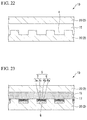
- FIG. 22 is a cross-sectional view of a membrane vesicle recovery device 1D according to the fifth embodiment of the present invention.
- the membrane vesicle recovery device according to this embodiment includes a base material (reaction base) 2C having recessed sections 4 and a smooth base material (reaction base) 2D.
- the membrane vesicle recovery device according to this embodiment includes a flow path 15 which is provided between the two base materials.
- the flow path 15 can send a liquid to the recessed sections 4.
- the recessed sections 4 are filled with a filler 8 through the flow path 15, and an organic solvent containing a lipid solution is sent to the recessed sections 4. Thereafter, an aqueous solvent 17 is then sent to the recessed sections 4.
- a fused membrane 5 which covers the filler 8 and blocks a recessed section 4 can be coupled to each of the recessed sections 4 as shown in FIG. 23 .
- the type of solvent is not particularly limited as long as this aqueous solvent 17 has a configuration in which a hydrophilic section of the fused membrane 5 faces the aqueous solvent like the buffer solution 16 illustrated in FIGS. 14A and 14B . Examples thereof include a sample such as serum or blood, a reagent, and an aqueous solution such as a buffer.
- the aqueous solvent may contain a membrane vesicle.
- the recessed sections may be formed of resin, glass, or the like, or may be formed of the same materials as those of the base materials.
- the recessed sections may be integrated with the base materials through resin molding processing or the like.
- the resin can be selected from cycloolefin polymers, silicon, polypropylene, polycarbonate, polystyrene, polyethylene, and polyvinyl acetate, but is not limited thereto.
- the base material may be formed of a material having rigidity, and may be formed of resin, glass, or the like. In the case of observing micropores through transmission, the base material may be transparent.
- a hydrophobic section may be formed through photolithography, and a material such as CYTOP (manufactured by Asahi Glass Co., Ltd.), which is highly hydrophobic, can be selected as the resin.
- a plate made of PDMS and in which micropores (well and recessed sections) with a diameter of 1 ⁇ m and a depth of 1 ⁇ m were arranged in an array shape by imprinting were prepared. Then, only the well sections were subjected to hydrophilic processing by performing plasma processing using a plasma-generating device. One side of the plate was set to 1 cm and the thickness thereof was set to 5 mm, and 9 x 10 6 wells were arranged in the center.
- oxotitanium phthalocyanine was dissolved in 10 mL of dichloromethane containing 0.1 mol/L trichloroacetic acid to prepare a sample solution for an LB membrane.
- This sample solution was added dropwise to the water surface to form a monomolecular membrane, and an LB membrane was produced using a commercially available LB membrane production device.
- the monomolecular membrane was transferred onto the surface of the plate by pulling up the plate in which the wells were filled with the invader reaction reagent and which had been sunk in a water tank in advance. Then, a bilayer membrane was produced after the plate was sunk in the water tank again.
- oligonucleotide as a substrate was sealed in a liposome reagent (Thermo Fisher Scientific Inc., Lipofectamine) and was then diluted in stages to obtain a sample solution as a model of an exosome. Thereafter, the sample solution was added dropwise to the top of a well plate filled with an invader reaction reagent of the above-described (1). A cover glass was placed thereon and was lightly pressed. The plate was incubated in an oven at 62°C for 15 minutes.
- a liposome reagent Thermo Fisher Scientific Inc., Lipofectamine
- the fluorescent amount of wells after the reaction was measured (by obtaining an average value of each fluorescent amount of 21 pixels after selecting 5 wells) using a fluorescence microscope (Carl Zeiss, AX10), an objective lens (EC Plan-Neofluar 40 x oil NA 1.3), a light source (Lithium Energy Japan, FluoArc 001.26A Usable with HBO 10), a sensor (Hamamatsu Photonics K.K., EM-CCD C9100), a filter (Olympus Corporation, U-MNIBA2), and analysis software (Hamamatsu Photonics K.K., AQUACOSMOS 2.6: exposure time of 64.3 ms, EM gain of 180, offset of 0, binning x 1), and the number of wells exhibiting fluorescence was measured. As a result, it was confirmed that the number of wells exhibiting a constant amount of fluorescence was increased in accordance with the amount of liposome.
- a glass base material having a thickness of 0.5 mm was spin-coated with CYTOP (manufactured by Asahi Glass Co., Ltd.) and was heat-cured for 3 hours at 180°C, and micropore chips each having one million micropores (well or recessed sections) with a diameter of 5 ⁇ m were produced using a photolithography technique.
- a glass base material with a feeding port was provided on the top of a micropore chip such that the gap between the micropore chips and the glass base became 100 ⁇ m. Accordingly, a flow path which is provided between two base materials was produced. The flow path can send a liquid to the micropores.
- An invader reaction reagent (1 ⁇ M allele probe, 0.4 ⁇ M invader oligo, 1 ⁇ M FAM label arm, 20 ⁇ M MOPS pH7.5, 15 mM NaCl, 6.25 mM MgCl 2 , and 50 U/ ⁇ L cleavase) was sent to the recessed sections through the sample ports, and the minute recessed sections were filled with the reaction reagent through deaeration.
- oligonucleotide as a substrate was sealed in a liposome reagent (Thermo Fisher Scientific Inc., Lipofectamine) to obtain a sample solution as a model of an exosome. Thereafter, the sample solution was sent to the top of the wells filled with the above-described invader reaction reagent. The sample solution was made into droplets by further sending oil to the wells. Thereafter, the wells were incubated in an oven at 62°C for 15 minutes. The fluorescent amount of each well after the reaction was measured using a fluorescence microscope. The measurement results are shown in FIG. 23 .
- the hydrophobic section 7b of the fused membrane 5 may be coupled to the surface 3 of the reaction base 2, as described in the above-described first embodiment.
- the present invention can be used to separate exosomes, organelles, and other membrane vesicles.
- the present invention can be used in the analysis of constituents of a membrane vesicle.
Landscapes
- Life Sciences & Earth Sciences (AREA)
- Health & Medical Sciences (AREA)
- Chemical & Material Sciences (AREA)
- Engineering & Computer Science (AREA)
- General Health & Medical Sciences (AREA)
- Molecular Biology (AREA)
- Bioinformatics & Cheminformatics (AREA)
- Organic Chemistry (AREA)
- Physics & Mathematics (AREA)
- Biochemistry (AREA)
- Wood Science & Technology (AREA)
- Biotechnology (AREA)
- Zoology (AREA)
- Immunology (AREA)
- Analytical Chemistry (AREA)
- Biomedical Technology (AREA)
- Microbiology (AREA)
- General Physics & Mathematics (AREA)
- Proteomics, Peptides & Aminoacids (AREA)
- Biophysics (AREA)
- Pathology (AREA)
- Hematology (AREA)
- General Engineering & Computer Science (AREA)
- Genetics & Genomics (AREA)
- Cell Biology (AREA)
- Urology & Nephrology (AREA)
- Bioinformatics & Computational Biology (AREA)
- Sustainable Development (AREA)
- Medicinal Chemistry (AREA)
- Food Science & Technology (AREA)
- Clinical Laboratory Science (AREA)
- Chemical Kinetics & Catalysis (AREA)
- Apparatus Associated With Microorganisms And Enzymes (AREA)
- Investigating Or Analysing Biological Materials (AREA)
- Measuring Or Testing Involving Enzymes Or Micro-Organisms (AREA)
- Peptides Or Proteins (AREA)
Abstract
Description
- The present invention relates to an instrument and a method which relate to separation and analysis of membrane vesicles in the biological field, the biochemical field, the biotechnological field, the medical field, and the medicinal field.
- Priority is claimed on Japanese Patent Application No.
2013-222751, filed October 25, 2013 - In the related art, in a structure such as a membrane vesicle from a living body such as a cell or a cell organelle or an artificial membrane vesicle covered by a lipid bilayer membrane, the content of this structure or a substance held on the lipid bilayer membrane has been analyzed.
- In recent years, as a method for transmitting information between cells, a method using an exosome which is a vesicle having a lipid bilayer membrane has attracted attention.
- Exosomes contain protein, mRNA, micro RNA (miRNA), DNA, or the like therein, and are membrane vesicles known to be able to transmit information to a destination cell by moving between cells. For example, it is known that in cells in which exosomes containing micro RNA from cancer cells are present, an immune function is activated or metastasis ability is acquired.
- In exosomes, in addition to genetic information and other signal factors within cells from which exosomes are released, factors that control functions of other cells to which the exosomes are accepted are included. Therefore, it is considered that it is possible to utilize exosomes as a new biomarker source for diagnosing diseases.
- For example,
PTLs -
PTL 2 discloses that each RNA is measured for determining the efficiency of treatment using a small interfering RNA (siRNA) therapeutic agent or a miRNA therapeutic agent. -
PTL 4 discloses that a protein marker which becomes an indicator of risk of onset of a cardiovascular event is detected. -
PTL 5 discloses that a disease such as cancer or infertility associated with the production of an autoantibody can be diagnosed by measuring the level of immunoreactive autoantibody. -
PTL 6 discloses that a vesicle stress response and a renal disease which is associated with the response can be detected by measuringaquaporin 1 of an exosome in urine. - An exosome can be prepared after being separated from a sample which can contain an exosome through separation such as ultracentrifugation or density gradient ultracentrifugation using a density difference. In addition, an exosome can also be separated through methods disclosed in
PTL -
- [PTL 1] Japanese Unexamined Patent Application, First Publication No.
2013-102768 - [PTL 2] Published Japanese Translation No.
2011-524164 of the PCT - [PTL 3] Published Japanese Translation No.
2010-534480 of the PCT - [PTL 4] Published Japanese Translation No.
2013-516619 of the PCT - [PTL 5] Published Japanese Translation No.
2010-517048 of the PCT - [PTL 6] Japanese Unexamined Patent Application, First Publication No.
2013-7698 - [PTL 7] Published Japanese Translation No.
2003-531864 of the PCT - [PTL 8] Published Japanese Translation No.
2002-535665 of the PCT - For example, in the case of separating an exosome through centrifugation, it is impossible to avoid impurities other than the exosome from being mixed in the separated exosome, and therefore, there is a limit to improve analysis accuracy and reproducibility.
- In addition, in the ultracentrifugation, the density gradient ultracentrifugation, or the like, the work procedure for separating an exosome is complicated and it requires a long period of time to separate and purify an exosome.
- In addition, a separation kit in the related art which simply separates an exosome has inferior reliability since purification of an exosome is insufficiently performed.
- It is also known that an exosome is selectively separated and purified using tetraspanin existing in a lipid bilayer membrane of an exosome. Tetraspanin is, for example, a 4-pass transmembrane type membrane protein family known to have 33 members in a human. Particularly, CD9, CD63, and CD81 are known as exosome markers. However, in the case where an exosome is separated and purified using an anti-tetraspanin monoclonal antibody, in some cases, an ununiformity is caused in an exosome finally separated and purified depending on the type of antigen to be separated.
- In addition, in some cases, the membrane structure of an exosome is destroyed in order to analyze the exosome. In this case, the content of the exosome is diluted in the exosome destruction process. Even if it is necessary to concentrate a product obtained by destroying an exosome in a diluted state, it is difficult to concentrate the product since there may be components which are degenerated or lost in the concentration process. In addition, in the case where protein of an exosome is to be analyzed, it is impossible to amplify protein to be analyzed in vitro unlike in the case of a nucleic acid. Therefore, it is necessary to analyze an exosome without diluting the exosome, if possible.
- The present invention has been made in consideration of the above-described circumstances, and an object of the present invention is to provide a membrane vesicle recovery device in which a membrane vesicle is not destroyed and constituents of the membrane vesicle are barely diluted, and which can selectively recover a membrane vesicle; a membrane vesicle recovery method; and a membrane vesicle analysis method which is simple and is excellent in accuracy and reproducibility.
- A membrane vesicle recovery device according to a first embodiment of the present invention includes: a liquid filler; and a fused membrane including a lipid bilayer membrane which covers at least a part of an outer periphery of the liquid filler, in which a content of a membrane vesicle is mixed into the liquid filler through fusing of the membrane vesicle and the fused membrane.
- The membrane vesicle recovery device according to the above-described first embodiment may further include: a reaction base having a surface on which a plurality of holding sections which is configured to hold the liquid filler are formed, in which the liquid filler is covered with the fused membrane in each of the holding sections.
- In the above-described first embodiment, the holding sections may be recessed sections formed in the reaction base, in the recessed sections, the fused membrane may come into contact with an opening end forming a boundary between the surface and each of the recessed sections and may be provided in the reaction base so as to block the recessed sections, and the recessed sections may be filled with the liquid filler.
- In the above-described first embodiment, a plurality of the fused membranes may be provided in the reaction base so as to be coupled to a part along the opening end in the inner wall surface of the recessed sections and to individually block each of the plurality of recessed sections.
- In the above-described first embodiment, in the reaction base, at least the inner wall surface may be hydrophobic and a hydrophobic section of the fused membrane may be coupled to the inner wall surface.
- In the above-described first embodiment, the fused membrane may be formed in a planar shape along the surface and formed in a series of membrane shape which blocks recessed sections.
- In the above-described first embodiment, the fused membrane may contain a membrane charge adjustment substance promoting membrane fusion between the fused membrane and the membrane vesicle which is derived from a living body or an artificial vesicle and which is covered by the lipid bilayer membrane.
- In the above-described first embodiment, the membrane charge adjustment substance may contain at least one of a membrane-destroying peptide, a membrane fusogenic polymer, a pH-sensitive polymer, and virus-derived membrane fusion protein.
- In the above-described first embodiment, the liquid filler may contain a solvent and a reaction reagent for biochemical analysis contained in the solvent.
- In the above-described first embodiment, the reaction reagent for biochemical analysis may contain a pH indicator.
- In the above-described first embodiment, the liquid filler may be a gel or sol.
- The membrane vesicle recovery device according to the above-described first embodiment may further include: a reaction base which has a surface on which a plurality of hydrophilic sections and hydrophobic sections surrounding the hydrophilic sections are formed, in which the liquid filler is provided in the hydrophilic sections, and the fused membrane is coupled to the hydrophobic sections in a boundary between each of the hydrophilic sections and each of the hydrophobic sections and wraps the liquid filler.
- A membrane vesicle recovery method according to a second embodiment of the present invention is a membrane vesicle recovery method for recovering a membrane vesicle which is derived from a living body or an artificial vesicle and which is covered by a lipid bilayer membrane in the membrane vesicle recovery device according to the above-described first embodiment. The method includes: subjecting the fused membrane and the membrane vesicle to membrane fusion by bringing a sample containing the membrane vesicle into contact with the fusion membrane.
- The membrane vesicle recovery method according to the second embodiment of the present invention may further include: adding a pH regulator which makes the sample acidic to the sample, and then, bringing the acidic sample into contact with the fused membrane.
- A membrane vesicle analysis method according to a third embodiment of the present invention is a membrane vesicle recovery method for analyzing the content, membrane protein, or a membrane lipid of a membrane vesicle which is derived from a living body or an artificial vesicle and which is covered by a lipid bilayer membrane. The method includes: fusing the membrane vesicle into the fused membrane of the membrane vesicle recovery device according to the above-described first embodiment; and holding the membrane protein or the membrane lipid on the membrane vesicle at the fused membrane.
- A membrane vesicle analysis method according to a fourth embodiment of the present invention is a membrane vesicle recovery method for analyzing the content, membrane protein, or a membrane lipid of a membrane vesicle which is derived from a living body or an artificial vesicle and which is covered by a lipid bilayer membrane. The method includes: fusing the membrane vesicle into the fused membrane of the membrane vesicle recovery device according to according to the above-described first embodiment; and reacting the reaction reagent for biochemical analysis with the content, membrane protein, or a membrane lipid of the membrane vesicle within the liquid filler.
- In the membrane vesicle analysis method using the membrane vesicle recovery device according to the above-described first embodiment or the membrane vesicle analysis method according to the above-described fourth embodiment, the reaction reagent for biochemical analysis may contain at least one of a nucleic acid analysis reagent, an invader reaction reagent, a protein analysis reagent, a lipid analysis reagent, an immunoassay reagent, and a homogeneous antigen-antibody reaction reagent.
- According to the above-described embodiments of the present invention, it is possible to provide a membrane vesicle recovery device and a membrane vesicle recovery method in which constituents of the membrane vesicle are barely diluted, and which can selectively recover a membrane vesicle, and a membrane vesicle analysis method that is simple, and is excellent in accuracy and reproducibility.
-
-
FIG. 1 is a perspective view showing a membrane vesicle recovery device according to a first embodiment of the present invention. -
FIG. 2 is an enlarged view of the section shown by a reference numeral X inFIG. 1 . -
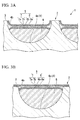
FIG. 3A is a schematic cross-sectional view taken along line A-A ofFIG. 2 . -
FIG. 3B is a cross-sectional view showing another configuration example of the membrane vesicle recovery device according to the first embodiment of the present invention. -
FIG. 4 is a view illustrating a production process of the membrane vesicle recovery device according to the first embodiment of the present invention. -
FIG. 5 is a view illustrating a production process of the membrane vesicle recovery device according to the first embodiment of the present invention. -
FIG. 6 is a view illustrating a production process of the membrane vesicle recovery device according to the first embodiment of the present invention. -
FIG. 7 is a view illustrating a production process of the membrane vesicle recovery device according to the first embodiment of the present invention. -
FIG. 8 is a view illustrating a production process of the membrane vesicle recovery device according to the first embodiment of the present invention. -
FIG. 9 is a view illustrating a production process of the membrane vesicle recovery device according to the first embodiment of the present invention. -
FIG. 10 is a view illustrating a production process of the membrane vesicle recovery device according to the first embodiment of the present invention. -
FIG. 11 is a view illustrating a production process of the membrane vesicle recovery device according to the first embodiment of the present invention. -
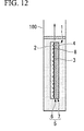
FIG. 12 is a view illustrating a production process of the membrane vesicle recovery device according to the first embodiment of the present invention. -
FIG. 13 is a schematic view showing another configuration example of the membrane vesicle recovery device according to the first embodiment of the present invention. -
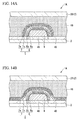
FIG. 14A is a schematic view showing still another configuration example of the membrane vesicle recovery device according to the first embodiment of the present invention. -
FIG. 14B is a schematic view showing still another configuration example of the membrane vesicle recovery device according to the first embodiment of the present invention. -
FIG. 15 is a view illustrating a membrane vesicle recovery method in which the membrane vesicle recovery device according to the first embodiment of the present invention is used. -
FIG. 16 is a view illustrating a membrane vesicle recovery method in which the membrane vesicle recovery device according to the first embodiment of the present invention is used. -
FIG. 17 is a view illustrating a membrane vesicle recovery method in which the membrane vesicle recovery device according to the first embodiment of the present invention is used. -
FIG. 18 is a schematic cross-sectional view showing a membrane vesicle recovery device according to a second embodiment of the present invention and is a cross-sectional view of the same line as line B-B ofFIG. 2 . -
FIG. 19 is a schematic enlarged view ofFIG. 18 . -
FIG. 20 is a schematic enlarged cross-sectional view showing a membrane vesicle recovery device according to a third embodiment of the present invention. -
FIG. 21 is a schematic enlarged cross-sectional view showing a membrane vesicle recovery device according to a fourth embodiment of the present invention. -
FIG. 22 is a schematic enlarged cross-sectional view showing a membrane vesicle recovery device according to a fifth embodiment of the present invention. -
FIG. 23 is a schematic enlarged cross-sectional view showing a membrane vesicle recovery device according to the fifth embodiment of the present invention. -
FIG. 24 is a view showing the results in which the fluorescence quantity in wells after reaction in the membrane vesicle recovery device according to the present invention was measured. - A first embodiment of the present invention will be described.
FIG. 1 is a perspective view showing a membrane vesicle recovery device of this embodiment.FIG. 2 is an enlarged view of the section shown by a reference numeral X inFIG. 1 .FIG. 3 is a schematic cross-sectional view taken along line A-A ofFIG. 2 . - As shown in
FIGS. 1 to 3B , a membranevesicle recovery device 1 of this embodiment includes areaction base 2, a fusedmembrane 5, and afiller 8. - The
reaction base 2 is a plate member in which a plurality of recessedsections 4 are formed on asurface 3. In thereaction base 2, an openingend 4b of a recessedsection 4 and thesurface 3 are hydrophobic. In this embodiment, thereaction base 2 is made of glass or silicon. A fine well which forms a recessedsection 4 is produced on the surface of thereaction base 2 after the surface of thereaction base 2 is subjected to hydrophobic processing through disilazane processing. In this embodiment, aninner wall surface 4a of the recessedsection 4 is hydrophilic. - The fused
membrane 5 is a lipid bilayer membrane which covers the recessedsection 4. That is, the fusedmembrane 5 has afirst layer 6 which is positioned at a position close to thereaction base 2 and asecond layer 7 which is stacked on thefirst layer 6. Thefirst layer 6 and thesecond layer 7 respectively havehydrophilic sections hydrophobic sections membrane 5 comes into contact with the openingend 4b which forms a boundary between the recessedsection 4 and thesurface 3 of thereaction base 2 in the recessedsection 4. The fusedmembrane 5 of this embodiment is coupled to a section along the openingend 4b of the recessedsection 4 in theinner wall surface 4a of the recessedsection 4. In addition, in this embodiment, a plurality of fusedmembranes 5 are respectively provided with respect to the recessedsections 4 of thereaction base 2 so as to individually block the plurality of recessedsections 4. - In a recessed
section 4, the hydrophobic sections of a fusedmembrane 5, the openingend 4b of the recessedsection 4, and thehydrophobic surface 3 are coupled to each other. - The
filler 8 is a liquid with which the recessedsection 4 is filled. In addition, thefiller 8 may be a gel or sol. It is preferable that thefiller 8 have a composition in which degeneration or decomposition does not occur with respect to a membrane vesicle to be recovered. In addition, thefiller 8 may contain a substance for decomposing or inactivating a substance which affects analysis in the membrane vesicle to be recovered. In addition, in this embodiment, there is an aqueous solvent (not shown) on the surface opposite to the surface facing thefiller 8 of the fusedmembrane 5. - Next, a method for producing the membrane
vesicle recovery device 1 of this embodiment will be described.FIGS. 4 to 12 are views illustrating a process of producing the membranevesicle recovery device 1. - First, the
reaction base 2 is molded. Thereaction base 2 is molded by disposing the recessedsections 4, which have a size large enough to house a membrane vesicle such as anexosome 11, in an array shape with respect to abase material 9 formed of plate-like glass or a plate-like resin member, as shown inFIG. 4 . The array of the recessedsections 4 is formed in thebase material 9 through transference of the recessed sections to thebase material 9 using a mold, or through cutting of thebase material 9. - The recessed
sections 4 may have a shape with, for example, a diameter of 1 µm and a depth of 1 µm. - In addition, in the case where the
base material 9 is formed of a hydrophilic material, hydrophobic processing is performed on the outer surface of thebase material 9 after the recessedsections 4 are molded. The hydrophobic processing is reforming of the surface, for example, disilazane processing performed on the outer surface of thebase material 9. - Next, as shown in
FIGS. 4 and 5 , a recessedsection 4 formed in thereaction base 2 is filled with thefiller 8. Thefiller 8 may be a liquid within awater tank 100 in a process in which the fusedmembrane 5 is coupled to the recessedsection 4 and which will be described below. - Next, the fused
membrane 5 which blocks a recessedsection 4 is coupled to each of the recessedsections 4. The fusedmembrane 5 is formed of a two-dimensional solid membrane 10 (refer toFIG. 7 ) which is obtained by dissolving amphipathic molecules such as arachidonic acids or stearic acids in an organic solvent which is then developed on the water surface in thewater tank 100 shown inFIG. 6 , and by compressing the molecules using a barrier. This two-dimensionalsolid membrane 10 is a monomolecular membrane constituting thefirst layer 6 and thesecond layer 7 in the lipid bilayer membrane. In a state in which the two-dimensionalsolid membrane 10 is formed on the water surface, ahydrophilic section 10a comes into contact with the water surface and ahydrophobic section 10b is exposed to outside air. - In order to couple the fused
membrane 5 to thereaction base 2, first, as shown inFIG. 7 , the above-described two-dimensionalsolid membrane 10 is formed on the water surface after holding thereaction base 2 in thewater tank 100. Subsequently, as shown inFIG. 8 , thereaction base 2 in thewater tank 100 is pulled up from thewater tank 100 while maintaining the two-dimensionalsolid membrane 10 on the water surface to be in a solid state. The two-dimensionalsolid membrane 10 is adhered to thesurface 3 of thereaction base 2 such that the two-dimensionalsolid membrane 10 covers the recessedsections 4 of thesurface 3 of thereaction base 2 by pulling up thereaction base 2 such that thesurface 3 on which the recessedsections 4 in thereaction base 2 are formed became vertical. As shown inFIG. 9 , the two-dimensionalsolid membrane 10 which had been adhered to thereaction base 2 became afirst layer 6 of the fusedmembrane 5. - After the two-dimensional
solid membrane 10 covers the recessedsections 4 and is adhered to thesurface 3 of thereaction base 2, as shown inFIG. 10 , thereaction base 2 is inserted into thewater tank 100 again. At this time, the above-described two-dimensionalsolid membrane 10 exists on the water surface. - As shown in
FIG. 11 , thehydrophobic section 10b of the two-dimensionalsolid membrane 10 formed on the water surface is brought into contact with thehydrophobic section 6b of thefirst layer 6 through the insertion of thereaction base 2 into thewater tank 100, and thesecond layer 7 of the fusedmembrane 5 is formed so as to cover the recessedsections 4 on thesurface 3 of thereaction base 2. - After the
first layer 6 and thesecond layer 7 of the fusedmembrane 5 are formed on thesurface 3 of thereaction base 2, as shown inFIG. 12 , the two-dimensionalsolid membrane 10 is removed from the water surface, and then, the membranevesicle recovery device 1 is pulled up from thewater tank 100. In sections which are not the recessedsections 4 on thesurface 3 of thereaction base 2, thefirst layer 6 of the fusedmembrane 5 is removed from thesurface 3 due to a weak coupling force ofhydrophilic section 6a in thefirst layer 6 of the fusedmembrane 5 with respect to thesurface 3 which is subjected to hydrophobic processing. Then, a section in the vicinity of the openingend 4b of a recessedsection 4 is coupled to thehydrophobic section 6b of the fused membrane 5 (refer toFIG. 3A ). Therefore, a plurality of recessedsections 4 are individually blocked by fusedmembranes 5. In addition, in some cases, thehydrophobic section 7b of a fusedmembrane 5 becomes a state of being coupled to the surface 3 (refer toFIG. 3B ). Even in this case, a plurality of recessedsections 4 are blocked. - The recessed
section 4 included in thereaction base 2 in this embodiment may not be formed in the vertical direction. For example, the recessedsection 4 may be formed in, for example, the horizontal direction with respect to the surface direction of thereaction base 2, as shown inFIG. 13 . - That is, the
reaction base 2 may have anintermediate layer 2A in which a recessedsection 4 is formed and a pair ofouter layers 2B interposing theintermediate layer 2A therebetween, and the fusedmembrane 5 may be formed in the recessedsection 4 which is formed in theintermediate layer 2A. As a method for forming a lipid bilayer membrane to be provided in thereaction base 2, a method disclosed in Japanese Unexamined Patent Application, First Publication No.2009-128206 - In addition, the
reaction base 2 in this embodiment need not have a recessedsection 4. For example, the reaction base may have ahydrophilic section 4A and ahydrophobic section 4B on a plane, as shown inFIG. 14A or 14B , instead of the recessedsection 4. In this case, thehydrophilic section 4A functions as the above-described recessedsection 4. That is, thefiller 8 remains in thehydrophilic section 4A having hydrophilic properties, the fusedmembrane 5 is provided so as to cover thefiller 8, and the fusedmembrane 5 is coupled to thehydrophobic section 4B in the vicinity of a boundary between thehydrophilic section 4A and thehydrophobic section 4B. - A tool having such a configuration can be produced by, for example, forming a lipid bilayer membrane on the surfaces of liquid droplets provided on a plane through the method disclosed in Japanese Unexamined Patent Application, First Publication No.
2009-128206 filler 8 between theouter layers 2B shown inFIGS. 14A and 14B , an organic solvent containing a lipid solution is poured thereinto, and a buffer solution containing no lysate is then poured thereinto. As such, it is possible to form the fusedmembrane 5 of a lipid bilayer membrane that covers the outer surface of thefiller 8. The fusedmembrane 5 has any shape shown inFIG. 14A or 14B depending on the hydrophobicity of thehydrophobic section 4B of thereaction base 2 and the type of solute. - Next, a membrane vesicle recovery method using the membrane
vesicle recovery device 1 will be described. -
FIGS. 15 to 17 are views illustrating the membrane vesicle recovery method using the membranevesicle recovery device 1. - The membrane vesicle recovery method of the present embodiment is a method for recovering a membrane vesicle which is derived from a living body or an artificial vesicle and which is covered by the lipid bilayer membrane in the membrane
vesicle recovery device 1 of this embodiment. - In this embodiment, an example of recovering an
exosome 11 is shown as an example of recovering a membrane vesicle. - First, a sample which can contain an
exosome 11 is prepared. The sample which can contain anexosome 11 may be, for example, a body fluid or a culture supernatant of a culture cell. In addition, a solution which is artificially prepared and contains liposome may be used as the sample. - Subsequently, the fused
membrane 5 and theexosome 11 are subjected to membrane fusion by bringing the sample into contact with the fusedmembrane 5, as shown inFIGS. 15 and 16 . - In the
reaction base 2 in which recessedsections 4 are arranged in an array shape, the fusedmembrane 5 which is formed of a lipid bilayer membrane that blocks each of the recessedsections 4 is coupled to aninner wall surface 4a (refer toFIGS. 3A and 3B ) of each of the recessedsections 4. Thus, if a membrane vesicle such as anexosome 11 approaches the fusedmembrane 5, the content of the membrane vesicle such as theexosome 11 is moved to the inside of each of the recessedsections 4 through membrane fusion (refer toFIG. 17 ). In the process in which the content of the membrane vesicle is moved to the inside of each of the recessedsections 4, the inside of theexosome 11 and the external environment are separated by the lipid bilayer membrane in a state in which the inside of theexosome 11 and the inside of each of the recessedsections 4 communicate with each other. Thus, each of the recessedsections 4 becomes a container in which the contents ofexosomes 11 are accommodated, and are blocked and closed by the lipid bilayer membrane, after the fusion of theexosomes 11 without diffusion of the contents ofexosomes 11 in the external environment. - Although the membrane fusion by the lipid bilayer membrane is a spontaneous nature of the lipid bilayer membrane, a repulsive force (repelling force) by a negative electric charge of a phosphate group of a phospholipid constituting the membrane blocks the membrane fusion. A negative electric charge on the membrane of the
exosome 11 and a negative electric charge of the fusedmembrane 5 may be combined with each other in order to make the membrane vesicle such as theexosome 11 be fused into the fusedmembrane 5 at a high frequency. However, the negative electric charge on theexosome 11 depends on the membrane protein of theexosome 11, and therefore, the adjustment of the negative electric charge of the fusedmembrane 5 in combination with theexosome 11 can be complicated. - It is important to shorten the physical distance between the membrane vesicle and the fused
membrane 5 in order to fuse the membrane vesicle into the fusedmembrane 5 at a high frequency. In the case where the volume of asolution containing exosomes 11 is small, the physical distance between anexosome 11 and the fusedmembrane 5 is shortened, and therefore, the frequency at which theexosome 11 comes into contact with the fusedmembrane 5 becomes high. In addition, even in the case where the concentration ofexosomes 11 in the solution containing theexosomes 11 is high, the frequency at which anexosome 11 comes into contact with the fusedmembrane 5 becomes high. In addition, there is also a high possibility that a plurality ofexosomes 11 are recovered in one recessedsection 4 if only the concentration ofexosomes 11 is increased. - It is possible to increase the efficiency of membrane fusion even by bringing a sample which has become acidic after adding a pH regulator that makes the sample acidic into contact with the fused
membrane 5. - Next, a membrane vesicle analysis method using the membrane
vesicle recovery device 1 of this embodiment will be described. - The membrane
vesicle recovery device 1 of this embodiment can analyze molecules as constituents of anexosome 11 after trapping a membrane vesicle such as theexosome 11 in the recessedsection 4. - In this embodiment, by fusing the membrane vesicle such as the
exosome 11 into the fusedmembrane 5 of the membranevesicle recovery device 1, the content of theexosome 11 is held in thefiller 8 and membrane protein or a membrane lipid of theexosome 11 is held on the fusedmembrane 5. - Thus, it is possible to analyze the constituents of the
exosome 11 in each of the recessedsections 4. Examples of analysis of transmembrane protein or the like which is held on the fusedmembrane 5 include immunoassay. Specific examples of the analysis method include determination of the quantity of CD9, CD63, and CD81, which are known to be highly expressed in theexosome 11. CD9, CD63, and CD81 are held on the fusedmembrane 5 through fusing of theexosome 11 into the fusedmembrane 5, and therefore, it is possible to perform quantitative determination using an anti-CD9 antibody, an anti-CD63 antibody, and an anti-CD81 antibody. - According to the membrane vesicle analysis method of this embodiment, it is possible to perform detection and quantitative determination of biomolecules derived from a membrane vesicle in the recessed
sections 4. Accordingly, it is possible to perform a simple and accurate analysis with high reproducibility with respect to the constituents contained in the membrane vesicle. - A second embodiment of the present invention will be described.
FIG. 18 is a schematic cross-sectional view showing a membrane vesicle recovery device of this embodiment and is a cross-sectional view of the same line as line B-B ofFIG. 2 .FIG. 19 is a schematic enlarged view ofFIG. 18 . - As shown in
FIGS. 18 and 19 , a membranevesicle recovery device 1A of this embodiment includes areaction base 2A made of a different material from that of thereaction base 2 , instead of thereaction base 2 described in the first embodiment. - In this embodiment, the
surface 3A of thereaction base 2A is hydrophilic. For example, thereaction base 2A of this embodiment is formed of a hydrophilic material. In the case where the base material of thereaction base 2A is formed of a hydrophobic material, hydrophilic processing is performed on the outer surface of the base material after recessedsections 4 are molded. The hydrophilic processing is reforming of the surface, for example, plasma processing performed on the outer surface of the base material. - In this embodiment, the hydrophilic section of the fused
membrane 5 is favorably coupled to thesurface 3A of thereaction base 2A. Thus, the fusedmembrane 5 is formed in a planar shape along thesurface 3A of thereaction base 2A and is formed in a series of membrane shapes which block the plurality of recessedsections 4. - Even with such a configuration, the same effect as that in the above-described first embodiment is exhibited.
- A third embodiment of the present invention will be described.
FIG. 20 is a schematic enlarged cross-sectional view showing a membrane vesicle recovery device of this embodiment. - In a membrane
vesicle recovery device 1B of this embodiment shown inFIG. 20 , a fusedmembrane 5 contains a membranecharge adjustment substance 12 promoting fusion between a membrane vesicle and the fusedmembrane 5. - The membrane
charge adjustment substance 12 contains at least one of a membrane-destroying peptide, a membrane fusogenic polymer, a pH-sensitive polymer, and virus-derived membrane fusion protein. - In the membrane
vesicle recovery device 1 B of this embodiment, when a solution containing exosomes is added to the fusedmembrane 5 so as to be brought into contact with the fusedmembrane 5, the membranecharge adjustment substance 12 incorporated into the fusedmembrane 5 promotes membrane fusion on the membrane vesicle by adjusting the membrane charge of the fusedmembrane 5. - In this embodiment, the recovery efficiency of a membrane vesicle such as an exosome is higher compared to the above-described first and second embodiments.
- A fourth embodiment of the present invention will be described.
FIG. 21 is a schematic enlarged cross-sectional view showing a membrane vesicle recovery device of this embodiment. - In a membrane vesicle recovery device 1C of this embodiment shown in
FIG. 21 , thefiller 8 contains a solvent 13 and a reaction reagent forbiochemical analysis 14 which is contained in the solvent 13. The reaction reagent forbiochemical analysis 14 contains at least one of a nucleic acid analysis reagent, an invader reaction reagent, a protein analysis reagent, a lipid analysis reagent, an immunoassay reagent, and a homogeneous antigen-antibody reaction reagent. - In addition, in this embodiment, the
filler 8 may be formed in a state in which the reaction reagent forbiochemical analysis 14 is dissolved in an aqueous buffer as the solvent 13, or may be formed by being processed into a gel or sol. If thefiller 8 is a gel or sol, it is difficult for the reaction reagent forbiochemical analysis 14 to be diffused in the water tank 100 (refer toFIG. 7 ) when areaction base 2 is put into thewater tank 100 during the production of the membrane vesicle recovery device 1C. - Next, a membrane vesicle analysis method using the membrane vesicle recovery device 1 C of this embodiment will be described.
- The membrane vesicle analysis method of this embodiment is a method for analyzing the content, membrane protein, or a membrane lipid of a membrane vesicle from a living body or an artificial vesicle and which is covered by a lipid bilayer membrane within a recessed
section 4. - In this embodiment, a membrane vesicle such as an exosome is fused into the fused
membrane 5 in the same manner as that described in the above-described first embodiment. - In this embodiment, there is a reaction reagent for
biochemical analysis 14 such as an enzyme or a substrate which reacts with an analysis object in thefiller 8 with which a recessedsection 4 has been filled in advance. Therefore, it is possible to cause a reaction in accordance with the type of reaction reagent forbiochemical analysis 14 in the recessedsection 4. - For example, in the case of detecting other nucleic acids such as micro RNA, an oligonucleotide, a polymerase, and a fluorescent reagent for detection may be put into the recessed
section 4. Alternately, in the case of detecting protein, a homogeneous immunoassay reagent in which fluorescence resonance energy transfer (FRET) may occur through a sandwich reaction of antibodies labeled with fluorescence may be included in the recessedsection 4. - In this embodiment, it is possible to analyze a substance within the recessed
section 4 in a state in which external impurities do not enter the recessedsection 4. Therefore, it is unnecessary to perform cleaning in order to remove impurities. Therefore, it is possible to eliminate the possibility that an analysis object is degenerated or lost through cleaning. Therefore, this embodiment is excellent in analysis accuracy and reproducibility compared to a method requiring cleaning in a process of separating and purifying anexosome 11 and a process of analyzing anexosome 11. - Furthermore, it is possible to rapidly perform a biochemical reaction on an analysis object incorporated into a recessed
section 4 by making the recessedsection 4 contain a reagent which is required for analysis. Therefore, it is possible to simply perform analysis on a substance or the like of which the activity is rapidly lost in an experiment system. - Furthermore, according to the membrane vesicle recovery device 1C, the membrane vesicle recovery method, and the membrane vesicle analysis method of this embodiment, the recessed
section 4 contains the reaction reagent forbiochemical analysis 14, and therefore, it is possible to simply and rapidly perform analysis on constituents of a membrane vesicle such as an exosome subsequently to separation of the membrane vesicle. - In addition, by performing detection of tetraspanin on the fused
membrane 5 and biochemical analysis in recessedsections 4 together, it is possible to distinguish a recessedsection 4 containing an exosome and a recessedsection 4 containing no exosome among a plurality of recessedsections 4 on thereaction base 2 and to obtain biochemical analysis results obtained by targeting only the recessedsection 4 containing an exosome. - It is possible to estimate how many exosomes are contained in one recessed
section 4 by determining an amount of tetraspanin in each of the recessedsections 4. - Next, a modification example of the above-described embodiment will be described with reference to
FIG. 21 . - In this modification example, the reaction reagent for
biochemical analysis 14 shown inFIG. 21 further contains a pH indicator in addition to the above-described reagent. In this modification example, it is possible to distinguish recessedsections 4 containing anexosome 11 and recessedsections 4 containing noexosome 11 among a plurality of recessedsections 4 on thereaction base 2 using the pH indicator. - In addition, by using the membrane
vesicle recovery device 1 configured such that the volume of a recessedsection 4 and the amount of pH indicator became constant with respect to each of the recessedsections 4, it is possible to estimate howmany exosomes 11 are contained in one recessedsection 4 using the pH indicator. - A fifth embodiment of the present invention will be described.
FIG. 22 is a cross-sectional view of a membranevesicle recovery device 1D according to the fifth embodiment of the present invention. The membrane vesicle recovery device according to this embodiment includes a base material (reaction base) 2C having recessedsections 4 and a smooth base material (reaction base) 2D. In addition, the membrane vesicle recovery device according to this embodiment includes aflow path 15 which is provided between the two base materials. Theflow path 15 can send a liquid to the recessedsections 4. The recessedsections 4 are filled with afiller 8 through theflow path 15, and an organic solvent containing a lipid solution is sent to the recessedsections 4. Thereafter, an aqueous solvent 17 is then sent to the recessedsections 4. Accordingly, a fusedmembrane 5 which covers thefiller 8 and blocks a recessedsection 4 can be coupled to each of the recessedsections 4 as shown inFIG. 23 . The type of solvent is not particularly limited as long as this aqueous solvent 17 has a configuration in which a hydrophilic section of the fusedmembrane 5 faces the aqueous solvent like thebuffer solution 16 illustrated inFIGS. 14A and 14B . Examples thereof include a sample such as serum or blood, a reagent, and an aqueous solution such as a buffer. In addition, the aqueous solvent may contain a membrane vesicle. - In the membrane vesicle recovery device according to this embodiment, the recessed sections may be formed of resin, glass, or the like, or may be formed of the same materials as those of the base materials. In addition, the recessed sections may be integrated with the base materials through resin molding processing or the like. The resin can be selected from cycloolefin polymers, silicon, polypropylene, polycarbonate, polystyrene, polyethylene, and polyvinyl acetate, but is not limited thereto. The base material may be formed of a material having rigidity, and may be formed of resin, glass, or the like. In the case of observing micropores through transmission, the base material may be transparent. In addition, a hydrophobic section may be formed through photolithography, and a material such as CYTOP (manufactured by Asahi Glass Co., Ltd.), which is highly hydrophobic, can be selected as the resin.
- Next, the membrane vesicle recovery device, the membrane vesicle recovery method, and the membrane vesicle analysis method of this embodiment will be described in more detail based on Examples shown below.
- A plate made of PDMS and in which micropores (well and recessed sections) with a diameter of 1 µm and a depth of 1 µm were arranged in an array shape by imprinting were prepared. Then, only the well sections were subjected to hydrophilic processing by performing plasma processing using a plasma-generating device. One side of the plate was set to 1 cm and the thickness thereof was set to 5 mm, and 9 x 10⁶ wells were arranged in the center. In order to fill the wells with an invader reaction reagent (1 µM allele probe, 0.4 µM invader oligo, 1 µM FAM label arm, 20 µM MOPS pH7.5, 15 mM NaCl, 6.25 mM MgCl2, and 50 U/µL cleavase), 5 µL of a reagent solution was added dropwise to the plate which was then covered with a cover glass. After injecting the reagent solution into the wells under reduced pressure, the cover glass was removed and air-dried.
- 0.0013 g of oxotitanium phthalocyanine was dissolved in 10 mL of dichloromethane containing 0.1 mol/L trichloroacetic acid to prepare a sample solution for an LB membrane. This sample solution was added dropwise to the water surface to form a monomolecular membrane, and an LB membrane was produced using a commercially available LB membrane production device. The monomolecular membrane was transferred onto the surface of the plate by pulling up the plate in which the wells were filled with the invader reaction reagent and which had been sunk in a water tank in advance. Then, a bilayer membrane was produced after the plate was sunk in the water tank again.
- An oligonucleotide as a substrate was sealed in a liposome reagent (Thermo Fisher Scientific Inc., Lipofectamine) and was then diluted in stages to obtain a sample solution as a model of an exosome. Thereafter, the sample solution was added dropwise to the top of a well plate filled with an invader reaction reagent of the above-described (1). A cover glass was placed thereon and was lightly pressed. The plate was incubated in an oven at 62°C for 15 minutes. The fluorescent amount of wells after the reaction was measured (by obtaining an average value of each fluorescent amount of 21 pixels after selecting 5 wells) using a fluorescence microscope (Carl Zeiss, AX10), an objective lens (EC Plan-Neofluar 40 x oil NA 1.3), a light source (Lithium Energy Japan, FluoArc 001.26A Usable with HBO 10), a sensor (Hamamatsu Photonics K.K., EM-CCD C9100), a filter (Olympus Corporation, U-MNIBA2), and analysis software (Hamamatsu Photonics K.K., AQUACOSMOS 2.6: exposure time of 64.3 ms, EM gain of 180, offset of 0, binning x 1), and the number of wells exhibiting fluorescence was measured. As a result, it was confirmed that the number of wells exhibiting a constant amount of fluorescence was increased in accordance with the amount of liposome.
- A glass base material having a thickness of 0.5 mm was spin-coated with CYTOP (manufactured by Asahi Glass Co., Ltd.) and was heat-cured for 3 hours at 180°C, and micropore chips each having one million micropores (well or recessed sections) with a diameter of 5 µm were produced using a photolithography technique. A glass base material with a feeding port was provided on the top of a micropore chip such that the gap between the micropore chips and the glass base became 100 µm. Accordingly, a flow path which is provided between two base materials was produced. The flow path can send a liquid to the micropores. An invader reaction reagent (1 µM allele probe, 0.4 µM invader oligo, 1 µM FAM label arm, 20 µM MOPS pH7.5, 15 mM NaCl, 6.25 mM MgCl2, and 50 U/µL cleavase) was sent to the recessed sections through the sample ports, and the minute recessed sections were filled with the reaction reagent through deaeration. 40 µL of hexadecane in which a mixed lipid of DOPE and DOPG is dissolved to be 4 mg/ml, was sent to the recessed sections. 40 µL of a buffer (20 µM MOPS pH 7.5, 15 mM NaCl, 6.25 mM MgCl2) was sent to the recessed sections.
- An oligonucleotide as a substrate was sealed in a liposome reagent (Thermo Fisher Scientific Inc., Lipofectamine) to obtain a sample solution as a model of an exosome. Thereafter, the sample solution was sent to the top of the wells filled with the above-described invader reaction reagent. The sample solution was made into droplets by further sending oil to the wells. Thereafter, the wells were incubated in an oven at 62°C for 15 minutes. The fluorescent amount of each well after the reaction was measured using a fluorescence microscope. The measurement results are shown in
FIG. 23 . - In the above, the embodiments and the examples of the present invention have been described in detail with respect to the drawings. However, specific configurations are not limited to these embodiments, and modifications or the like to the design can be included within a scope not departing from the gist of the present invention.
- For example, in the above-described
embodiments hydrophobic section 7b of the fusedmembrane 5 may be coupled to thesurface 3 of thereaction base 2, as described in the above-described first embodiment. - In addition, the constituents shown in each of the above-described embodiments can be configured by being appropriately combined.
- The present invention can be used to separate exosomes, organelles, and other membrane vesicles.
- In addition, the present invention can be used in the analysis of constituents of a membrane vesicle.
-
- 1, 1A, 1B, 1C, 1D
- membrane vesicle recovery device
- 2
- reaction base
- 3
- surface
- 4
- recessed section
- 5
- fused membrane
- 6
- first layer
- 6a
- hydrophilic section
- 6b
- hydrophobic section
- 7
- second layer
- 7a
- hydrophilic section
- 7b
- hydrophobic section
- 8
- filler
- 9
- base material
- 10
- two-dimensional solid membrane
- 10a
- hydrophilic section
- 10b
- hydrophobic section
- 11
- exosome
- 12
- membrane charge adjustment substance
- 13
- solvent
- 14
- reaction reagent for biochemical analysis
Claims (17)
- A membrane vesicle recovery device, comprising:a liquid filler; anda fused membrane including a lipid bilayer membrane which covers at least a part of an outer periphery of the liquid filler, whereina content of a membrane vesicle is mixed into the liquid filler through fusing of the membrane vesicle and the fused membrane.
- The membrane vesicle recovery device according to Claim 1, further comprising:a reaction base having a surface on which a plurality of holding sections which is configured to hold the liquid filler are formed, whereinthe liquid filler is covered with the fused membrane in each of the holding sections.
- The membrane vesicle recovery device according to Claim 2, whereinthe holding sections are recessed sections formed in the reaction base,in the recessed sections, the fused membrane comes into contact with an opening end forming a boundary between the surface and each of the recessed sections and is provided in the reaction base so as to block the recessed sections, andthe recessed sections are filled with the liquid filler.
- The membrane vesicle recovery device according to Claim 3, whereina plurality of the fused membranes are provided in the reaction base so as to be coupled to a part along the opening end in the inner wall surface of the recessed sections and to individually block each of the plurality of recessed sections.
- The membrane vesicle recovery device according to Claim 4, whereinin the reaction base, at least the inner wall surface is hydrophobic and a hydrophobic section of the fused membrane is coupled to the inner wall surface.
- The membrane vesicle recovery device according to Claim 3, whereinthe fused membrane is formed in a planar shape along the surface and is formed in a series of membrane shape which blocks recessed sections.
- The membrane vesicle recovery device according to Claim 3, whereinthe fused membrane contains a membrane charge adjustment substance promoting membrane fusion between the fused membrane and the membrane vesicle which is derived from a living body or an artificial vesicle and which is covered by the lipid bilayer membrane.
- The membrane vesicle recovery device according to Claim 7, whereinthe membrane charge adjustment substance contains at least one of a membrane-destroying peptide, a membrane fusogenic polymer, a pH-sensitive polymer, and virus-derived membrane fusion protein.
- The membrane vesicle recovery device according to any one of Claims 1 to 8, whereinthe liquid filler contains a solvent and a reaction reagent for biochemical analysis contained in the solvent.
- The membrane vesicle recovery device according to Claim 9, whereinthe reaction reagent for biochemical analysis contains a pH indicator.
- The membrane vesicle recovery device according to any one of Claims 1 to 10, whereinthe liquid filler is a gel or sol.
- The membrane vesicle recovery device according to Claim 1, further comprising:a reaction base which has a surface on which a plurality of hydrophilic sections and hydrophobic sections surrounding the hydrophilic sections are formed, whereinthe liquid filler is provided in the hydrophilic sections, and the fused membrane is coupled to the hydrophobic sections in a boundary between each of the hydrophilic sections and each of the hydrophobic sections and wraps the liquid filler.
- A membrane vesicle recovery method for recovering a membrane vesicle which is derived from a living body or an artificial vesicle and which is covered by a lipid bilayer membrane in the membrane vesicle recovery device according to any one of Claims 1 to 12, the method comprising:subjecting the fused membrane and the membrane vesicle to membrane fusion by bringing a sample containing the membrane vesicle into contact with the fusion membrane.
- The membrane vesicle recovery method according to Claim 13, comprising:adding a pH regulator which makes the sample acidic to the sample, and then, bringing the acidic sample into contact with the fused membrane.
- A membrane vesicle analysis method for analyzing the content, membrane protein, or a membrane lipid of a membrane vesicle which is derived from a living body or an artificial vesicle and which is covered by a lipid bilayer membrane, the method comprising:fusing the membrane vesicle into the fused membrane of the membrane vesicle recovery device according to any one of Claims 1 to 12; andholding the membrane protein or the membrane lipid on the membrane vesicle at the fused membrane.
- A membrane vesicle analysis method for analyzing the content, membrane protein, or a membrane lipid of a membrane vesicle which is derived from a living body or an artificial vesicle and which is covered by a lipid bilayer membrane, the method comprising:fusing the membrane vesicle into the fused membrane of the membrane vesicle recovery device according to Claim 9 or 10; andreacting the reaction reagent for biochemical analysis with the content, membrane protein, or a membrane lipid of the membrane vesicle within the liquid filler.
- The membrane vesicle analysis method using the membrane vesicle recovery device according to Claim 9 or 10 or the membrane vesicle analysis method according to Claim 16, whereinthe reaction reagent for biochemical analysis contains at least one of a nucleic acid analysis reagent, an invader reaction reagent, a protein analysis reagent, a lipid analysis reagent, an immunoassay reagent, and a homogeneous antigen-antibody reaction reagent.
Applications Claiming Priority (2)
| Application Number | Priority Date | Filing Date | Title |
|---|---|---|---|
| JP2013222751 | 2013-10-25 | ||
| PCT/JP2014/078405 WO2015060446A1 (en) | 2013-10-25 | 2014-10-24 | Membrane vesicle recovery device, membrane vesicle recovery method, and membrane vesicle analysis method |
Publications (3)
| Publication Number | Publication Date |
|---|---|
| EP3061807A1 true EP3061807A1 (en) | 2016-08-31 |
| EP3061807A4 EP3061807A4 (en) | 2017-06-28 |
| EP3061807B1 EP3061807B1 (en) | 2019-03-06 |
Family
ID=52993031
Family Applications (1)
| Application Number | Title | Priority Date | Filing Date |
|---|---|---|---|
| EP14856558.3A Active EP3061807B1 (en) | 2013-10-25 | 2014-10-24 | Membrane vesicle recovery device, membrane vesicle recovery method, and membrane vesicle analysis method |
Country Status (5)
| Country | Link |
|---|---|
| US (1) | US10627327B2 (en) |
| EP (1) | EP3061807B1 (en) |
| JP (1) | JP6547625B2 (en) |
| CN (1) | CN105658782B (en) |
| WO (1) | WO2015060446A1 (en) |
Families Citing this family (4)
| Publication number | Priority date | Publication date | Assignee | Title |
|---|---|---|---|---|
| CN110072994A (en) * | 2016-12-23 | 2019-07-30 | 埃克波菲尔有限公司 | Methods and compositions for purification or isolation of microvesicles and exosomes |
| DE102020210450A1 (en) | 2020-08-18 | 2022-02-24 | Robert Bosch Gesellschaft mit beschränkter Haftung | Analysis cartridge, method for producing a membrane for an analysis cartridge and method for operating an analysis cartridge |
| JP2024029862A (en) * | 2022-08-23 | 2024-03-07 | 国立大学法人神戸大学 | Analysis method for exosome membrane-bound molecules |
| CN116500007A (en) * | 2023-04-26 | 2023-07-28 | 谱天(天津)生物科技有限公司 | A Method for Evaluating Vesicle Extraction Efficiency Using Fluorescent Liposomes |
Family Cites Families (17)
| Publication number | Priority date | Publication date | Assignee | Title |
|---|---|---|---|---|
| US6758961B1 (en) * | 1997-12-17 | 2004-07-06 | Ecole Polytechnique Federale De Lausanne | Positioning and electrophysiological characterization of individual cells and reconstituted membrane systems on microstructured carriers |
| US7244349B2 (en) * | 1997-12-17 | 2007-07-17 | Molecular Devices Corporation | Multiaperture sample positioning and analysis system |
| FR2788780B1 (en) | 1999-01-27 | 2001-03-30 | Ap Cells Inc | PROCESS FOR THE PREPARATION OF MEMBRANE VESICLES |
| US20040241176A1 (en) | 2000-04-27 | 2004-12-02 | Ap Cells. Inc. | Method of producing membrane vesicles |
| US20050230272A1 (en) * | 2001-10-03 | 2005-10-20 | Lee Gil U | Porous biosensing device |
| EP1815847A3 (en) * | 2002-10-11 | 2008-11-05 | Idea Ag | Aggregate with increased deformability, comprising at least three amphipats, for improved transport through semi-permeable barriers and for the non-invasive drug application in vivo, especially through the skin |
| JP4250523B2 (en) * | 2003-12-25 | 2009-04-08 | 株式会社東芝 | Microreactor, analysis system, analysis method, reaction system, reaction method, separation system, separation method |
| WO2008092164A2 (en) | 2007-01-26 | 2008-07-31 | University Of Louisville Research Foundation, Inc. | Methods of detecting autoantibodies for diagnosing and characterizing disorders |
| US7829272B2 (en) * | 2007-05-24 | 2010-11-09 | Nanotrope Inc. | Viral detection liposomes and method |
| EP2613149B1 (en) | 2007-07-25 | 2014-09-17 | University Of Louisville Research Foundation, Inc. | Exosome-associated microRNA as a diagnostic marker |
| JP5441142B2 (en) * | 2007-11-26 | 2014-03-12 | 国立大学法人 東京大学 | Microfluidic planar lipid bilayer array and analytical method using the planar lipid bilayer membrane |
| WO2009146143A2 (en) * | 2008-04-03 | 2009-12-03 | The Regents Of The University Of California | Ex-vivo multi-dimensional system for the separation and isolation of cells, vesicles, nanoparticles and biomarkers |
| US20110177054A1 (en) | 2008-06-06 | 2011-07-21 | Derrick Gibbings | Use of endo-lysosomal system and secreted vesicles (exosome-like) in treatments and diagnostics based on small rna and experimental study of small rna |
| GB0913823D0 (en) * | 2009-08-07 | 2009-09-16 | Isis Innovation | Bilayers |
| WO2011083145A1 (en) | 2010-01-08 | 2011-07-14 | Cavadis B.V. | Determination of exosomel biomarkers for predicting cardiovascular events |
| JP2013007698A (en) | 2011-06-27 | 2013-01-10 | Univ Of Miyazaki | Method for detecting endoplastic reticulum response in kidney |
| KR20130068530A (en) * | 2011-12-15 | 2013-06-26 | 삼성전자주식회사 | Methods for quantifying exosome in cell culture and method for increasing yield of exosome using thereof |
-
2014
- 2014-10-24 JP JP2015543937A patent/JP6547625B2/en active Active
- 2014-10-24 EP EP14856558.3A patent/EP3061807B1/en active Active
- 2014-10-24 WO PCT/JP2014/078405 patent/WO2015060446A1/en not_active Ceased
- 2014-10-24 CN CN201480058099.9A patent/CN105658782B/en active Active
-
2016
- 2016-04-22 US US15/135,919 patent/US10627327B2/en active Active
Also Published As
| Publication number | Publication date |
|---|---|
| EP3061807A4 (en) | 2017-06-28 |
| CN105658782B (en) | 2018-08-07 |
| WO2015060446A1 (en) | 2015-04-30 |
| JP6547625B2 (en) | 2019-07-24 |
| JPWO2015060446A1 (en) | 2017-03-09 |
| CN105658782A (en) | 2016-06-08 |
| EP3061807B1 (en) | 2019-03-06 |
| US20160238497A1 (en) | 2016-08-18 |
| US10627327B2 (en) | 2020-04-21 |
Similar Documents
| Publication | Publication Date | Title |
|---|---|---|
| Talebjedi et al. | Exploiting microfluidics for extracellular vesicle isolation and characterization: potential use for standardized embryo quality assessment | |
| Le et al. | Exosome isolation using nanostructures and microfluidic devices | |
| Contreras-Naranjo et al. | Microfluidics for exosome isolation and analysis: enabling liquid biopsy for personalized medicine | |
| TWI691724B (en) | Apparatus for detecting particle in fluid sample and method for isolating aliquot of fluid sample within microfluidic chip | |
| US20070059716A1 (en) | Methods for detecting fetal abnormality | |
| US20180275088A1 (en) | Devices and Methods for Sample Analysis | |
| CN111440696B (en) | Fetal cell capture module, microfluidic chip for fetal cell capture, and methods of using same | |
| US20070059718A1 (en) | Systems and methods for enrichment of analytes | |
| US20070059680A1 (en) | System for cell enrichment | |
| US20070059683A1 (en) | Veterinary diagnostic system | |
| US10627327B2 (en) | Membrane vesicle recovery device, membrane vesicle recovery method, and membrane vesicle analysis method | |
| EP3276357B1 (en) | Fluid device, system and method | |
| CN109136062A (en) | Digital fluid sample separation equipment and the method for quantifying sample analysis for a step | |
| WO2007035585A2 (en) | Systems and methods for enrichment of analytes | |
| US20150076049A1 (en) | Microfilter and apparatus for separating a biological entity from a sample volume | |
| CN101821626A (en) | double layer | |
| US20080067079A1 (en) | Method of Analyzing Sample and Analyzing Apparatus | |
| EP3974844A1 (en) | Method for detecting target molecule | |
| CN107709990A (en) | Systems and methods for detecting biomarkers | |
| US20240280592A1 (en) | METHOD FOR DETECTING AMYLOID-ß BOUND TO BRAIN-NEURONALCELL-DERIVED EXOSOME IN BLOOD, KIT FOR DETECTION OF AMYLOID-ß BOUND TO BRAIN-NEURONAL-CELL-DERIVED EXOSOME IN BLOOD, AND METHOD FOR EVALUATING ACCUMULATION LEVEL OF AMYLOID-ß IN BRAIN | |
| Mojtaba Mousavi et al. | Recent progress in prompt molecular detection of exosomes using CRISPR/Cas and microfluidic‐assisted approaches toward smart cancer diagnosis and analysis | |
| JP6730682B2 (en) | Electrophoresis device, electrophoretic device manufacturing method, and extracellular endoplasmic reticulum separation apparatus | |
| KR101718951B1 (en) | Biomolecular preconcentration device and fabrication method thereof | |
| US20080138831A1 (en) | Immunological assay and chip | |
| CN107206347B (en) | The operating method of magnetic substance particle manipulation device and magnetic substance particle |
Legal Events
| Date | Code | Title | Description |
|---|---|---|---|
| PUAI | Public reference made under article 153(3) epc to a published international application that has entered the european phase |
Free format text: ORIGINAL CODE: 0009012 |
|
| 17P | Request for examination filed |
Effective date: 20160426 |
|
| AK | Designated contracting states |
Kind code of ref document: A1 Designated state(s): AL AT BE BG CH CY CZ DE DK EE ES FI FR GB GR HR HU IE IS IT LI LT LU LV MC MK MT NL NO PL PT RO RS SE SI SK SM TR |
|
| AX | Request for extension of the european patent |
Extension state: BA ME |
|
| DAX | Request for extension of the european patent (deleted) | ||
| A4 | Supplementary search report drawn up and despatched |
Effective date: 20170530 |
|
| RIC1 | Information provided on ipc code assigned before grant |
Ipc: C12M 1/14 20060101ALI20170523BHEP Ipc: C12Q 1/00 20060101ALI20170523BHEP Ipc: C12M 1/26 20060101AFI20170523BHEP |
|
| GRAP | Despatch of communication of intention to grant a patent |
Free format text: ORIGINAL CODE: EPIDOSNIGR1 |
|
| STAA | Information on the status of an ep patent application or granted ep patent |
Free format text: STATUS: GRANT OF PATENT IS INTENDED |
|
| INTG | Intention to grant announced |
Effective date: 20181012 |
|
| GRAS | Grant fee paid |
Free format text: ORIGINAL CODE: EPIDOSNIGR3 |
|
| GRAA | (expected) grant |
Free format text: ORIGINAL CODE: 0009210 |
|
| STAA | Information on the status of an ep patent application or granted ep patent |
Free format text: STATUS: THE PATENT HAS BEEN GRANTED |
|
| AK | Designated contracting states |
Kind code of ref document: B1 Designated state(s): AL AT BE BG CH CY CZ DE DK EE ES FI FR GB GR HR HU IE IS IT LI LT LU LV MC MK MT NL NO PL PT RO RS SE SI SK SM TR |
|
| REG | Reference to a national code |
Ref country code: GB Ref legal event code: FG4D |
|
| REG | Reference to a national code |
Ref country code: CH Ref legal event code: EP Ref country code: AT Ref legal event code: REF Ref document number: 1104560 Country of ref document: AT Kind code of ref document: T Effective date: 20190315 |
|
| REG | Reference to a national code |
Ref country code: DE Ref legal event code: R096 Ref document number: 602014042559 Country of ref document: DE |
|
| REG | Reference to a national code |
Ref country code: IE Ref legal event code: FG4D |
|
| REG | Reference to a national code |
Ref country code: NL Ref legal event code: MP Effective date: 20190306 |
|
| REG | Reference to a national code |
Ref country code: LT Ref legal event code: MG4D |
|
| PG25 | Lapsed in a contracting state [announced via postgrant information from national office to epo] |
Ref country code: FI Free format text: LAPSE BECAUSE OF FAILURE TO SUBMIT A TRANSLATION OF THE DESCRIPTION OR TO PAY THE FEE WITHIN THE PRESCRIBED TIME-LIMIT Effective date: 20190306 Ref country code: NO Free format text: LAPSE BECAUSE OF FAILURE TO SUBMIT A TRANSLATION OF THE DESCRIPTION OR TO PAY THE FEE WITHIN THE PRESCRIBED TIME-LIMIT Effective date: 20190606 Ref country code: SE Free format text: LAPSE BECAUSE OF FAILURE TO SUBMIT A TRANSLATION OF THE DESCRIPTION OR TO PAY THE FEE WITHIN THE PRESCRIBED TIME-LIMIT Effective date: 20190306 Ref country code: LT Free format text: LAPSE BECAUSE OF FAILURE TO SUBMIT A TRANSLATION OF THE DESCRIPTION OR TO PAY THE FEE WITHIN THE PRESCRIBED TIME-LIMIT Effective date: 20190306 |
|
| PG25 | Lapsed in a contracting state [announced via postgrant information from national office to epo] |
Ref country code: HR Free format text: LAPSE BECAUSE OF FAILURE TO SUBMIT A TRANSLATION OF THE DESCRIPTION OR TO PAY THE FEE WITHIN THE PRESCRIBED TIME-LIMIT Effective date: 20190306 Ref country code: NL Free format text: LAPSE BECAUSE OF FAILURE TO SUBMIT A TRANSLATION OF THE DESCRIPTION OR TO PAY THE FEE WITHIN THE PRESCRIBED TIME-LIMIT Effective date: 20190306 Ref country code: GR Free format text: LAPSE BECAUSE OF FAILURE TO SUBMIT A TRANSLATION OF THE DESCRIPTION OR TO PAY THE FEE WITHIN THE PRESCRIBED TIME-LIMIT Effective date: 20190607 Ref country code: LV Free format text: LAPSE BECAUSE OF FAILURE TO SUBMIT A TRANSLATION OF THE DESCRIPTION OR TO PAY THE FEE WITHIN THE PRESCRIBED TIME-LIMIT Effective date: 20190306 Ref country code: RS Free format text: LAPSE BECAUSE OF FAILURE TO SUBMIT A TRANSLATION OF THE DESCRIPTION OR TO PAY THE FEE WITHIN THE PRESCRIBED TIME-LIMIT Effective date: 20190306 Ref country code: BG Free format text: LAPSE BECAUSE OF FAILURE TO SUBMIT A TRANSLATION OF THE DESCRIPTION OR TO PAY THE FEE WITHIN THE PRESCRIBED TIME-LIMIT Effective date: 20190606 |
|
| REG | Reference to a national code |
Ref country code: AT Ref legal event code: MK05 Ref document number: 1104560 Country of ref document: AT Kind code of ref document: T Effective date: 20190306 |
|
| PG25 | Lapsed in a contracting state [announced via postgrant information from national office to epo] |
Ref country code: CZ Free format text: LAPSE BECAUSE OF FAILURE TO SUBMIT A TRANSLATION OF THE DESCRIPTION OR TO PAY THE FEE WITHIN THE PRESCRIBED TIME-LIMIT Effective date: 20190306 Ref country code: RO Free format text: LAPSE BECAUSE OF FAILURE TO SUBMIT A TRANSLATION OF THE DESCRIPTION OR TO PAY THE FEE WITHIN THE PRESCRIBED TIME-LIMIT Effective date: 20190306 Ref country code: IT Free format text: LAPSE BECAUSE OF FAILURE TO SUBMIT A TRANSLATION OF THE DESCRIPTION OR TO PAY THE FEE WITHIN THE PRESCRIBED TIME-LIMIT Effective date: 20190306 Ref country code: EE Free format text: LAPSE BECAUSE OF FAILURE TO SUBMIT A TRANSLATION OF THE DESCRIPTION OR TO PAY THE FEE WITHIN THE PRESCRIBED TIME-LIMIT Effective date: 20190306 Ref country code: AL Free format text: LAPSE BECAUSE OF FAILURE TO SUBMIT A TRANSLATION OF THE DESCRIPTION OR TO PAY THE FEE WITHIN THE PRESCRIBED TIME-LIMIT Effective date: 20190306 Ref country code: ES Free format text: LAPSE BECAUSE OF FAILURE TO SUBMIT A TRANSLATION OF THE DESCRIPTION OR TO PAY THE FEE WITHIN THE PRESCRIBED TIME-LIMIT Effective date: 20190306 Ref country code: SK Free format text: LAPSE BECAUSE OF FAILURE TO SUBMIT A TRANSLATION OF THE DESCRIPTION OR TO PAY THE FEE WITHIN THE PRESCRIBED TIME-LIMIT Effective date: 20190306 Ref country code: PT Free format text: LAPSE BECAUSE OF FAILURE TO SUBMIT A TRANSLATION OF THE DESCRIPTION OR TO PAY THE FEE WITHIN THE PRESCRIBED TIME-LIMIT Effective date: 20190706 |
|
| PG25 | Lapsed in a contracting state [announced via postgrant information from national office to epo] |
Ref country code: PL Free format text: LAPSE BECAUSE OF FAILURE TO SUBMIT A TRANSLATION OF THE DESCRIPTION OR TO PAY THE FEE WITHIN THE PRESCRIBED TIME-LIMIT Effective date: 20190306 Ref country code: SM Free format text: LAPSE BECAUSE OF FAILURE TO SUBMIT A TRANSLATION OF THE DESCRIPTION OR TO PAY THE FEE WITHIN THE PRESCRIBED TIME-LIMIT Effective date: 20190306 |
|
| REG | Reference to a national code |
Ref country code: DE Ref legal event code: R097 Ref document number: 602014042559 Country of ref document: DE |
|
| PG25 | Lapsed in a contracting state [announced via postgrant information from national office to epo] |
Ref country code: AT Free format text: LAPSE BECAUSE OF FAILURE TO SUBMIT A TRANSLATION OF THE DESCRIPTION OR TO PAY THE FEE WITHIN THE PRESCRIBED TIME-LIMIT Effective date: 20190306 Ref country code: IS Free format text: LAPSE BECAUSE OF FAILURE TO SUBMIT A TRANSLATION OF THE DESCRIPTION OR TO PAY THE FEE WITHIN THE PRESCRIBED TIME-LIMIT Effective date: 20190706 |
|
| PLBE | No opposition filed within time limit |
Free format text: ORIGINAL CODE: 0009261 |
|
| STAA | Information on the status of an ep patent application or granted ep patent |
Free format text: STATUS: NO OPPOSITION FILED WITHIN TIME LIMIT |
|
| PG25 | Lapsed in a contracting state [announced via postgrant information from national office to epo] |
Ref country code: DK Free format text: LAPSE BECAUSE OF FAILURE TO SUBMIT A TRANSLATION OF THE DESCRIPTION OR TO PAY THE FEE WITHIN THE PRESCRIBED TIME-LIMIT Effective date: 20190306 |
|
| 26N | No opposition filed |
Effective date: 20191209 |
|
| PG25 | Lapsed in a contracting state [announced via postgrant information from national office to epo] |
Ref country code: SI Free format text: LAPSE BECAUSE OF FAILURE TO SUBMIT A TRANSLATION OF THE DESCRIPTION OR TO PAY THE FEE WITHIN THE PRESCRIBED TIME-LIMIT Effective date: 20190306 |
|
| PG25 | Lapsed in a contracting state [announced via postgrant information from national office to epo] |
Ref country code: TR Free format text: LAPSE BECAUSE OF FAILURE TO SUBMIT A TRANSLATION OF THE DESCRIPTION OR TO PAY THE FEE WITHIN THE PRESCRIBED TIME-LIMIT Effective date: 20190306 |
|
| PG25 | Lapsed in a contracting state [announced via postgrant information from national office to epo] |
Ref country code: MC Free format text: LAPSE BECAUSE OF FAILURE TO SUBMIT A TRANSLATION OF THE DESCRIPTION OR TO PAY THE FEE WITHIN THE PRESCRIBED TIME-LIMIT Effective date: 20190306 |
|
| REG | Reference to a national code |
Ref country code: CH Ref legal event code: PL |
|
| PG25 | Lapsed in a contracting state [announced via postgrant information from national office to epo] |
Ref country code: CH Free format text: LAPSE BECAUSE OF NON-PAYMENT OF DUE FEES Effective date: 20191031 Ref country code: LI Free format text: LAPSE BECAUSE OF NON-PAYMENT OF DUE FEES Effective date: 20191031 Ref country code: LU Free format text: LAPSE BECAUSE OF NON-PAYMENT OF DUE FEES Effective date: 20191024 |
|
| REG | Reference to a national code |
Ref country code: BE Ref legal event code: MM Effective date: 20191031 |
|
| PG25 | Lapsed in a contracting state [announced via postgrant information from national office to epo] |
Ref country code: BE Free format text: LAPSE BECAUSE OF NON-PAYMENT OF DUE FEES Effective date: 20191031 |
|
| GBPC | Gb: european patent ceased through non-payment of renewal fee |
Effective date: 20191024 |
|
| PG25 | Lapsed in a contracting state [announced via postgrant information from national office to epo] |
Ref country code: FR Free format text: LAPSE BECAUSE OF NON-PAYMENT OF DUE FEES Effective date: 20191031 Ref country code: GB Free format text: LAPSE BECAUSE OF NON-PAYMENT OF DUE FEES Effective date: 20191024 Ref country code: IE Free format text: LAPSE BECAUSE OF NON-PAYMENT OF DUE FEES Effective date: 20191024 |
|
| PG25 | Lapsed in a contracting state [announced via postgrant information from national office to epo] |
Ref country code: CY Free format text: LAPSE BECAUSE OF FAILURE TO SUBMIT A TRANSLATION OF THE DESCRIPTION OR TO PAY THE FEE WITHIN THE PRESCRIBED TIME-LIMIT Effective date: 20190306 |
|
| PG25 | Lapsed in a contracting state [announced via postgrant information from national office to epo] |
Ref country code: MT Free format text: LAPSE BECAUSE OF FAILURE TO SUBMIT A TRANSLATION OF THE DESCRIPTION OR TO PAY THE FEE WITHIN THE PRESCRIBED TIME-LIMIT Effective date: 20190306 Ref country code: HU Free format text: LAPSE BECAUSE OF FAILURE TO SUBMIT A TRANSLATION OF THE DESCRIPTION OR TO PAY THE FEE WITHIN THE PRESCRIBED TIME-LIMIT; INVALID AB INITIO Effective date: 20141024 |
|
| PG25 | Lapsed in a contracting state [announced via postgrant information from national office to epo] |
Ref country code: MK Free format text: LAPSE BECAUSE OF FAILURE TO SUBMIT A TRANSLATION OF THE DESCRIPTION OR TO PAY THE FEE WITHIN THE PRESCRIBED TIME-LIMIT Effective date: 20190306 |
|
| P01 | Opt-out of the competence of the unified patent court (upc) registered |
Effective date: 20230530 |
|
| PGFP | Annual fee paid to national office [announced via postgrant information from national office to epo] |
Ref country code: DE Payment date: 20250902 Year of fee payment: 12 |