EP3061596A1 - Fixation of fibre fabric layers in moulds for wind turbine blades - Google Patents
Fixation of fibre fabric layers in moulds for wind turbine blades Download PDFInfo
- Publication number
- EP3061596A1 EP3061596A1 EP15156916.7A EP15156916A EP3061596A1 EP 3061596 A1 EP3061596 A1 EP 3061596A1 EP 15156916 A EP15156916 A EP 15156916A EP 3061596 A1 EP3061596 A1 EP 3061596A1
- Authority
- EP
- European Patent Office
- Prior art keywords
- fibre fabric
- mechanical interlocking
- fabric layers
- interlocking elements
- mesh
- Prior art date
- Legal status (The legal status is an assumption and is not a legal conclusion. Google has not performed a legal analysis and makes no representation as to the accuracy of the status listed.)
- Granted
Links
Images

Classifications
-
- B—PERFORMING OPERATIONS; TRANSPORTING
- B29—WORKING OF PLASTICS; WORKING OF SUBSTANCES IN A PLASTIC STATE IN GENERAL
- B29C—SHAPING OR JOINING OF PLASTICS; SHAPING OF MATERIAL IN A PLASTIC STATE, NOT OTHERWISE PROVIDED FOR; AFTER-TREATMENT OF THE SHAPED PRODUCTS, e.g. REPAIRING
- B29C70/00—Shaping composites, i.e. plastics material comprising reinforcements, fillers or preformed parts, e.g. inserts
- B29C70/04—Shaping composites, i.e. plastics material comprising reinforcements, fillers or preformed parts, e.g. inserts comprising reinforcements only, e.g. self-reinforcing plastics
- B29C70/28—Shaping operations therefor
- B29C70/30—Shaping by lay-up, i.e. applying fibres, tape or broadsheet on a mould, former or core; Shaping by spray-up, i.e. spraying of fibres on a mould, former or core
- B29C70/36—Shaping by lay-up, i.e. applying fibres, tape or broadsheet on a mould, former or core; Shaping by spray-up, i.e. spraying of fibres on a mould, former or core and impregnating by casting, e.g. vacuum casting
-
- B—PERFORMING OPERATIONS; TRANSPORTING
- B32—LAYERED PRODUCTS
- B32B—LAYERED PRODUCTS, i.e. PRODUCTS BUILT-UP OF STRATA OF FLAT OR NON-FLAT, e.g. CELLULAR OR HONEYCOMB, FORM
- B32B27/00—Layered products comprising a layer of synthetic resin
- B32B27/36—Layered products comprising a layer of synthetic resin comprising polyesters
-
- B—PERFORMING OPERATIONS; TRANSPORTING
- B29—WORKING OF PLASTICS; WORKING OF SUBSTANCES IN A PLASTIC STATE IN GENERAL
- B29C—SHAPING OR JOINING OF PLASTICS; SHAPING OF MATERIAL IN A PLASTIC STATE, NOT OTHERWISE PROVIDED FOR; AFTER-TREATMENT OF THE SHAPED PRODUCTS, e.g. REPAIRING
- B29C70/00—Shaping composites, i.e. plastics material comprising reinforcements, fillers or preformed parts, e.g. inserts
- B29C70/04—Shaping composites, i.e. plastics material comprising reinforcements, fillers or preformed parts, e.g. inserts comprising reinforcements only, e.g. self-reinforcing plastics
- B29C70/28—Shaping operations therefor
- B29C70/54—Component parts, details or accessories; Auxiliary operations, e.g. feeding or storage of prepregs or SMC after impregnation or during ageing
- B29C70/543—Fixing the position or configuration of fibrous reinforcements before or during moulding
-
- B—PERFORMING OPERATIONS; TRANSPORTING
- B29—WORKING OF PLASTICS; WORKING OF SUBSTANCES IN A PLASTIC STATE IN GENERAL
- B29D—PRODUCING PARTICULAR ARTICLES FROM PLASTICS OR FROM SUBSTANCES IN A PLASTIC STATE
- B29D99/00—Subject matter not provided for in other groups of this subclass
- B29D99/0025—Producing blades or the like, e.g. blades for turbines, propellers, or wings
-
- B—PERFORMING OPERATIONS; TRANSPORTING
- B32—LAYERED PRODUCTS
- B32B—LAYERED PRODUCTS, i.e. PRODUCTS BUILT-UP OF STRATA OF FLAT OR NON-FLAT, e.g. CELLULAR OR HONEYCOMB, FORM
- B32B37/00—Methods or apparatus for laminating, e.g. by curing or by ultrasonic bonding
- B32B37/02—Methods or apparatus for laminating, e.g. by curing or by ultrasonic bonding characterised by a sequence of laminating steps, e.g. by adding new layers at consecutive laminating stations
-
- B—PERFORMING OPERATIONS; TRANSPORTING
- B32—LAYERED PRODUCTS
- B32B—LAYERED PRODUCTS, i.e. PRODUCTS BUILT-UP OF STRATA OF FLAT OR NON-FLAT, e.g. CELLULAR OR HONEYCOMB, FORM
- B32B37/00—Methods or apparatus for laminating, e.g. by curing or by ultrasonic bonding
- B32B37/12—Methods or apparatus for laminating, e.g. by curing or by ultrasonic bonding characterised by using adhesives
-
- B—PERFORMING OPERATIONS; TRANSPORTING
- B29—WORKING OF PLASTICS; WORKING OF SUBSTANCES IN A PLASTIC STATE IN GENERAL
- B29L—INDEXING SCHEME ASSOCIATED WITH SUBCLASS B29C, RELATING TO PARTICULAR ARTICLES
- B29L2031/00—Other particular articles
- B29L2031/08—Blades for rotors, stators, fans, turbines or the like, e.g. screw propellers
- B29L2031/082—Blades, e.g. for helicopters
- B29L2031/085—Wind turbine blades
-
- B—PERFORMING OPERATIONS; TRANSPORTING
- B32—LAYERED PRODUCTS
- B32B—LAYERED PRODUCTS, i.e. PRODUCTS BUILT-UP OF STRATA OF FLAT OR NON-FLAT, e.g. CELLULAR OR HONEYCOMB, FORM
- B32B2250/00—Layers arrangement
- B32B2250/20—All layers being fibrous or filamentary
-
- B—PERFORMING OPERATIONS; TRANSPORTING
- B32—LAYERED PRODUCTS
- B32B—LAYERED PRODUCTS, i.e. PRODUCTS BUILT-UP OF STRATA OF FLAT OR NON-FLAT, e.g. CELLULAR OR HONEYCOMB, FORM
- B32B2255/00—Coating on the layer surface
- B32B2255/02—Coating on the layer surface on fibrous or filamentary layer
-
- B—PERFORMING OPERATIONS; TRANSPORTING
- B32—LAYERED PRODUCTS
- B32B—LAYERED PRODUCTS, i.e. PRODUCTS BUILT-UP OF STRATA OF FLAT OR NON-FLAT, e.g. CELLULAR OR HONEYCOMB, FORM
- B32B2305/00—Condition, form or state of the layers or laminate
- B32B2305/38—Meshes, lattices or nets
-
- Y—GENERAL TAGGING OF NEW TECHNOLOGICAL DEVELOPMENTS; GENERAL TAGGING OF CROSS-SECTIONAL TECHNOLOGIES SPANNING OVER SEVERAL SECTIONS OF THE IPC; TECHNICAL SUBJECTS COVERED BY FORMER USPC CROSS-REFERENCE ART COLLECTIONS [XRACs] AND DIGESTS
- Y02—TECHNOLOGIES OR APPLICATIONS FOR MITIGATION OR ADAPTATION AGAINST CLIMATE CHANGE
- Y02P—CLIMATE CHANGE MITIGATION TECHNOLOGIES IN THE PRODUCTION OR PROCESSING OF GOODS
- Y02P70/00—Climate change mitigation technologies in the production process for final industrial or consumer products
- Y02P70/50—Manufacturing or production processes characterised by the final manufactured product
Definitions
- the present disclosure relates to a method of manufacturing a rotor blade for a wind turbine and a thread, a fibre fabric layer and a mesh for use in the manufacture of a rotor blade for a wind turbine.
- Wind turbine blades are commonly fabricated of fibre reinforced composite materials such as glass fibre reinforced epoxy plastic or carbon fibre reinforced epoxy plastic.
- a popular manufacturing method is VARTM or vacuum assisted resin transfer moulding technique which may also be employed for the present invention.
- a number of fibre fabric layers are placed in a mould forming a stack. The mould is closed and evacuated to low pressure by means of a vacuum pump. Then a liquid resin is infused into the laminate stack and left to cure. After cure, the item can be taken out of the mould and be finalised.
- the stiffness of the individual fabric layers helps stabilising the arrangement of the layer onto inclining or vertical surface portions of the mould before vacuum pressure finally consolidates and stabilises the lay-up.
- the root diameters of the blades also increase.
- the lay-up of reinforcement fabrics on the side walls in the root area of the mould for manufacturing a wind turbine rotor blade is no longer supported sufficiently by the inherent stiffness of the individual layers.
- the reinforcement material will slide towards the bottom of the mould cavity before infusion of the blade commences. When the blade is demoulded, the placement of fibre fabrics turns out to be erratic and the blade has to be repaired or even discarded.
- a liquid adhesive is applied in between the individual fabric layers in order to make the layers stick together and to prevent them from sliding towards the bottom of the mould.
- this tackifier is sprayed on the fabric layers.
- the aerosol spray is hazardous to occupational health because of volatile organic compounds of the adhesive such as Acetone.
- the adhesive may also contain Bisphenol-A powder or other hazardous epoxy components.
- the tackifier is sprayed on the fabric, the fibres are to some degree coated with the tackifier. This may prevent correct flow of the resin once it is infused into the fabric layer stack.
- thermoplastic which is called a hot melt. After application, the hot melt causes the neighbouring fabric layers to stick together. However, when the hot melt is applied with a spray gun by a worker, there is a risk that too much hot melt is applied in some areas and a thermoplastic film layer may form in some places. Since the thermoplastic layer is not soluble in the epoxy resin, it does not bond well to the resin which causes a risk of delamination failures in such laminates.
- a first aspect of the invention provides a method of manufacturing a rotor blade for a wind turbine.
- the method includes steps of:
- a step of interlocking the plurality of fibre fabric layers using at least one mechanical interlocking element is carried out prior to laminating the fibre fabric layers together.
- the inventive method is advantageous in that the mechanical interlocking elements, e.g. when placed between adjacent fibre fabric layers, attach to some of the fabric fibres of both adjacent fibre fabric layers. In this way the individual fabric layers are mechanically coupled such that none of the layers may slip on an underlying layer. Thus, the placement of the layers in the layer stack within the mould may be maintained throughout the following lamination procedure and quality and yield of the manufacture will increase.
- the mechanical interlocking elements may be fabricated from thermoplastic material, however, since the mechanical interlocking elements are located only at discrete points of the laminate, the thermoplastic will not form a layer impairing the robustness of the laminate.
- the at least one mechanical interlocking element may be provided together with and within one of the fibre fabric layers. If the mechanical interlocking elements are provided within the one fibre fabric layer, a step of distributing the mechanical interlocking elements across the fibre fabric layer can be ommited resulting in a faster manufacturing process. Furthermore, placement of the mechanical interlocking elements can be carried out during manufacture of the fibre fabric layer which ensures equidistant placement of the mechanical interlocking elements.
- the fibre fabric layer comprising the mechanical interlocking elements can be cut as needed and the patches tailored in this manner will always comprise a suitable number of mechanical interlocking elements that is approximately proportional to the surface area of the patch.
- the method of the invention may further includes a step of pressing the one of the fibre fabric layers. In this way a locking end of the at least one mechanical interlocking element provided within the one of the fibre fabric layers may be exposed.
- the plurality of fibre fabric layers may be interlocked by fastening the exposed locking end to a fibre fabric layer adjacent to the one fibre fabric layer. This provides for a very quick way of interlocking the individual fibre fabric layers.
- the method may further include arranging an additional fibre fabric layer onto the one of the fibre layers on a side of the one of the fibre layers opposing the neighbouring fibre fabric layer and fastening the additional fibre fabric layer to the one of the fibre fabric layers including the at least one mechanical interlocking element.
- a stack of fibre fabric layers may be formed easily by alternating fibre fabric layers with and without mechanical interlocking elements incorporated into the respective fibre fabric layer.
- the step of interlocking the plurality of fibre fabric layers may include injecting at least one mechanical interlocking element into the plurality of fibre fabric layers thereby perforating at least one of the fibre fabric layers with the at least one mechanical interlocking element.
- the mechanical interlocking element works like a dowel or peg effectively stapling the fibre fabric layers together.
- the injected mechanical interlocking element may be partially retracted to thereby fold out a plurality of barbs from the mechanical interlocking element.
- the barbs will grip the fabric and lock the laminate.
- the method of the invention may further include a step of placing a thread or mesh having a plurality of mechanical interlocking elements between two of the fibre fabric layers.
- the step of interlocking the plurality of fibre fabric layers may include fastening the two of the fibre fabric layers to the mechanical interlocking elements of the thread or mesh.
- a mesh includes openings that are much larger than the threads surrounding the openings. Contrary to this a fibre fabric has only very small openings - if any at all - and will usually appear opaque to the naked eye.
- the thread or mesh serves as a carrier for the mechanical interlocking elements to which the mechanical interlocking elements are attached. In this way the mechanical interlocking elements may be provided at preconfigured distances from each other. Since the mesh possesses large openings, the mesh hardly interferes with the lamination process such that bonding of the fibre fabric layers is of superior quality when compared to the prior art.
- the thread or mesh may be made from thermoplastic material.
- the method of the invention may further include a step of manufacturing a plurality of mechanical interlocking elements by cutting a helically shaped blank along a length direction of the blank. This provides a large number of mechanical interlocking elements having an arcuate or bent shape that may function as hooks.
- a second aspect of the invention provides a thread including a plurality of mechanical interlocking elements arranged along the thread and protruding from the thread in at least three different directions.
- the three different directions are at least approximately equiangularly arranged around the thread length axis. This ensures that always at least one mechanical interlocking element will lock to either one of the adjacent fibre fabric layers.
- Another aspect of the invention provides a fibre fabric layer for manufacturing a rotor blade for a wind turbine, the fibre fabric layer including a plurality of mechanical interlocking elements arranged across the fibre fabric layer.
- the fibre fabric layer may be used in the invention manufacturing method.
- the mechanical interlocking elements of the fibre fabric layer may be embedded into the fibre fabric layer.
- Yet another aspect of the invention provides a mesh including a plurality of mechanical interlocking elements arranged across the mesh.
- the mechanical interlocking elements protrude from both opposing sides of the mesh.
- the mesh may be placed between two layers of fibre fabric and be used to lock the two fibre fabric layers.
- the fibre fabric layer or the mesh may include a separator arranged on one side of the layer or mesh.
- the separator may be a paper or such and prevents the mechanical interlocking elements from locking to the fibre fabric layer or mesh itself. Using a separator, the fibre fabric layer or mesh may be rolled up and transported as a roll.
- the mechanical interlocking elements are made from thermoplastic material, preferably from thermoplastic polyester.
- Thermoplastic material is light-weight, inexpensive and may be processed and manufactured easily.
- the mechanical interlocking elements are formed as hooks or spikes.
- the hooks or spikes may have a length of about 0.5 to 5 millimetres.
- the hooks or spikes may have a diameter of about 0.1 to 1 millimetres.
- the dimensions given for a hook refer to the hook thread rather than to the size of the curved hook formed from the hook thread.
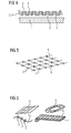
- Figure 1 shows a detail from a rotor blade manufactured using a first embodiment of the present invention.
- a plurality of fibre fabric layers 2 are placed in a mould 1 which defines an outer shape of a rotor blade for a wind turbine or a portion thereof.
- the mould 1 comprises an inclined portion where the layers 2 can slip out of place due to their own weight or that of the neighbouring layers 2.
- a deformed rotor blade may be formed due to an accidental displacement of the layers 2 in the mould 1.
- the invention proposes interlocking the layers 2 with each other by placing mechanical interlocking elements 3 at singular points having a distance from each other.
- Fig. 1 one example of such a mechanical interlocking element 3 is shown prior to and after insertion into the stack of fibre fabric layers 2.
- the mechanical interlocking element 3 assumes the form of a dowel or bolt that will perforate at least one of the fibre fabric layers 2 during insertion into the stack.
- the dowel or bolt 3 includes barbs 4 that will engage with the fibre fabric of the layers 2 once the inserted or injected dowel or bolt is slightly pulled backwards and will thereby interlock the fibre fabric layers 2.
- the mechanical interlocking element 3 as shown in Fig. 1 could be injected into the fibre fabric layers 2 using air pressure.
- Figure 2 shows an embodiment of a preferred fibre fabric layer according to the present invention.
- preconfigured produces including a plurality of mechanical interlocking elements 3 may be used.
- One such produce is a fibre fabric layer 2 wherein a plurality of mechanical interlocking elements 3 is embedded into the fabric.
- the mechanical interlocking elements 3 are completely hidden in the fabric while on the right side locking ends 5 of the mechanical interlocking elements are exposed on either sides of the fabric layer 2.
- the fabric layer 2 may be manufactured both with the locking ends of the mechanical interlocking elements covered or exposed. However, the configuration on the left hand side is preferred. This is because the fibre fabric layer 2 may be compressible and thus be pressed, e.g.
- the locking ends 5 of the mechanical interlocking elements will perforate the surface(s) of the fibre fabric layer 2 wherein they are embedded. This will expose the locking ends 5 as shown on the right side of Fig. 2 . The exposed locking ends 5 may then engage with an adjacent fibre fabric layer.
- the locking ends 5 assume the form of hooks, however, other forms may be used such as spikes with or without barbs.
- the mechanical interlocking elements 3 are embedded into the fibre fabric layer 2, there is no need for a separator paper or similar and the fibre fabric layer 2 may be transported in a rolled up manner and unrolled when needed during manufacture of the wind rotor blade.
- FIG. 3 shows an embodiment of a mesh 6 according to the present invention.
- the mesh 6 may have rectangular openings with the mechanical interlocking elements 3 arranged at the knots of the mesh, i.e. at the corners of the openings. Other configurations like triangular or hexagonal openings may be devised.
- the mesh 6 may be arranged between two neighbouring fibre fabric layers 2 during manufacture of the wind rotor blade.
- the mechanical interlocking elements 3 in Fig. 3 preferably include at least two locking ends oriented in opposing directions. For example, a pyramidal arrangement of four locking ends or an arrangement of six locking ends similar to that of a "Czech hedgehog" may be used. This guarantees that at least one locking end is inserted into either of the adjacent fibre fabric layers 2 during the manufacturing process.
- the large openings of the mesh 6 do not obstruct the flow of liquid resin to the effect that delamination failures observed in the prior art may be prevented. Since the mesh 6 may be flexible and the mechanical interlocking elements 3 may move relative to each other during transport or handling, the mesh 6 may be releasably attached to a separator having a light adhesive or the like applied at one side of the separator.
- Figure 4 shows a stack of interlocked fibre fabric layers according to the present invention.
- a plurality of fibre fabric layers 2 is arranged in a mould 1.
- a fibre fabric layer 2 including mechanical interlocking elements 3 or a mesh 6 as shown in Figs. 3 or 5 is placed between a bottom fibre fabric layer and a top fibre fabric layer.
- the stack of layers 2 is pressed against the mould 1 and locking ends of the mechanical interlocking elements 3 fasten the layers 2 to each other.
- Other layers 2 may be added with meshes 6 inserted in between as needed.
- the mechanical interlocking element 3 formed like a dowel or bolt as shown in Fig. 1 may be used in addition to the mesh 6 or layer 2 comprising the mechanical interlocking elements 3.
- the dowel or bolt may be used in places of the mould 1 that are particularly prone to deplacement of fibre fabric layers 2 during the manufacturing process of the wind rotor blade and where the degree of fixation provided by the mechanical interlocking elements of the mesh or fibre fabric layer appears insufficient.
- Figure 5 shows another embodiment of a mesh 6 according to the present invention.
- the mesh 6 is similar to that shown in Fig. 3 and what was said in conjunction with Fig. 3 also applies to the embodiment of Fig. 5 unless stated to the contrary.
- the mechanical interlocking elements 3 are formed as spikes.
- the spikes may have a triangular form optionally including barbs.
- the spikes may be formed similar to shark teeth.
- Figure 6 shows further inventive produces according to the invention.
- the mesh 6 of the invention may be applied to a separator 7 and may be rolled up. It is also possible to use rectangular or circular patches 8, 9 of mesh including mechanical interlocking elements.
- the invention also proposes a thread 10 including mechanical interlocking elements 3 distributed along the thread 10. The thread can be used in the same or similar fashion as described above for the mesh provided by the present invention.
Landscapes
- Engineering & Computer Science (AREA)
- Mechanical Engineering (AREA)
- Chemical & Material Sciences (AREA)
- Composite Materials (AREA)
- Textile Engineering (AREA)
- Wind Motors (AREA)
Abstract
- providing a mould (1) defining an outer shape of a the rotor blade or a portion thereof;
- arranging a plurality of fibre fabric layers (2) on a surface of the mould (1) having at least one inclined surface portion; and
- laminating the fibre fabrics layers (2) together by infusing a liquid resin into the mould (1). According to the invention a step of interlocking the plurality of fibre fabric layers (2) using at least one mechanical interlocking element (3) prior to laminating the fibre fabric layers (2) together is carried out.
Description
- The present disclosure relates to a method of manufacturing a rotor blade for a wind turbine and a thread, a fibre fabric layer and a mesh for use in the manufacture of a rotor blade for a wind turbine.
- Wind turbine blades are commonly fabricated of fibre reinforced composite materials such as glass fibre reinforced epoxy plastic or carbon fibre reinforced epoxy plastic. A popular manufacturing method is VARTM or vacuum assisted resin transfer moulding technique which may also be employed for the present invention. A number of fibre fabric layers are placed in a mould forming a stack. The mould is closed and evacuated to low pressure by means of a vacuum pump. Then a liquid resin is infused into the laminate stack and left to cure. After cure, the item can be taken out of the mould and be finalised.
- When the fabric layers are placed into the mould, the stiffness of the individual fabric layers helps stabilising the arrangement of the layer onto inclining or vertical surface portions of the mould before vacuum pressure finally consolidates and stabilises the lay-up. As wind turbine blades already reach lengths of 70 metres and continuously increase in size, the root diameters of the blades also increase. The lay-up of reinforcement fabrics on the side walls in the root area of the mould for manufacturing a wind turbine rotor blade is no longer supported sufficiently by the inherent stiffness of the individual layers. For large blades there are substantial problems in arranging and securing the fabric layers, especially on inclined surfaces. In some cases the reinforcement material will slide towards the bottom of the mould cavity before infusion of the blade commences. When the blade is demoulded, the placement of fibre fabrics turns out to be erratic and the blade has to be repaired or even discarded.
- To overcome this problem, a liquid adhesive is applied in between the individual fabric layers in order to make the layers stick together and to prevent them from sliding towards the bottom of the mould. Often this tackifier is sprayed on the fabric layers. However, the aerosol spray is hazardous to occupational health because of volatile organic compounds of the adhesive such as Acetone. The adhesive may also contain Bisphenol-A powder or other hazardous epoxy components. Furthermore, as the tackifier is sprayed on the fabric, the fibres are to some degree coated with the tackifier. This may prevent correct flow of the resin once it is infused into the fabric layer stack.
- Another tackifier system uses a thermoplastic which is called a hot melt. After application, the hot melt causes the neighbouring fabric layers to stick together. However, when the hot melt is applied with a spray gun by a worker, there is a risk that too much hot melt is applied in some areas and a thermoplastic film layer may form in some places. Since the thermoplastic layer is not soluble in the epoxy resin, it does not bond well to the resin which causes a risk of delamination failures in such laminates.
- To overcome one or more of the aforementioned problems, a first aspect of the invention provides a method of manufacturing a rotor blade for a wind turbine. The method includes steps of:
- providing a mould defining an outer shape of a the rotor blade or a portion thereof;
- arranging a plurality of fibre fabric layers on a surface of the mould having at least one inclined surface portion; and
- laminating the fibre fabrics layers together by infusing a liquid resin into the mould.
- According to the invention a step of interlocking the plurality of fibre fabric layers using at least one mechanical interlocking element is carried out prior to laminating the fibre fabric layers together.
- The inventive method is advantageous in that the mechanical interlocking elements, e.g. when placed between adjacent fibre fabric layers, attach to some of the fabric fibres of both adjacent fibre fabric layers. In this way the individual fabric layers are mechanically coupled such that none of the layers may slip on an underlying layer. Thus, the placement of the layers in the layer stack within the mould may be maintained throughout the following lamination procedure and quality and yield of the manufacture will increase.
- The mechanical interlocking elements may be fabricated from thermoplastic material, however, since the mechanical interlocking elements are located only at discrete points of the laminate, the thermoplastic will not form a layer impairing the robustness of the laminate.
- The at least one mechanical interlocking element may be provided together with and within one of the fibre fabric layers. If the mechanical interlocking elements are provided within the one fibre fabric layer, a step of distributing the mechanical interlocking elements across the fibre fabric layer can be ommited resulting in a faster manufacturing process. Furthermore, placement of the mechanical interlocking elements can be carried out during manufacture of the fibre fabric layer which ensures equidistant placement of the mechanical interlocking elements. The fibre fabric layer comprising the mechanical interlocking elements can be cut as needed and the patches tailored in this manner will always comprise a suitable number of mechanical interlocking elements that is approximately proportional to the surface area of the patch.
- When a fibre fabric layer containing the mechanical interlocking elements is used, the method of the invention may further includes a step of pressing the one of the fibre fabric layers. In this way a locking end of the at least one mechanical interlocking element provided within the one of the fibre fabric layers may be exposed. The plurality of fibre fabric layers may be interlocked by fastening the exposed locking end to a fibre fabric layer adjacent to the one fibre fabric layer. This provides for a very quick way of interlocking the individual fibre fabric layers.
- In particular, the method may further include arranging an additional fibre fabric layer onto the one of the fibre layers on a side of the one of the fibre layers opposing the neighbouring fibre fabric layer and fastening the additional fibre fabric layer to the one of the fibre fabric layers including the at least one mechanical interlocking element. A stack of fibre fabric layers may be formed easily by alternating fibre fabric layers with and without mechanical interlocking elements incorporated into the respective fibre fabric layer.
- Alternatively or additionally the step of interlocking the plurality of fibre fabric layers may include injecting at least one mechanical interlocking element into the plurality of fibre fabric layers thereby perforating at least one of the fibre fabric layers with the at least one mechanical interlocking element. Here the mechanical interlocking element works like a dowel or peg effectively stapling the fibre fabric layers together.
- Subsequently the injected mechanical interlocking element may be partially retracted to thereby fold out a plurality of barbs from the mechanical interlocking element. The barbs will grip the fabric and lock the laminate.
- The method of the invention may further include a step of placing a thread or mesh having a plurality of mechanical interlocking elements between two of the fibre fabric layers. The step of interlocking the plurality of fibre fabric layers may include fastening the two of the fibre fabric layers to the mechanical interlocking elements of the thread or mesh. Herein a mesh includes openings that are much larger than the threads surrounding the openings. Contrary to this a fibre fabric has only very small openings - if any at all - and will usually appear opaque to the naked eye. The thread or mesh serves as a carrier for the mechanical interlocking elements to which the mechanical interlocking elements are attached. In this way the mechanical interlocking elements may be provided at preconfigured distances from each other. Since the mesh possesses large openings, the mesh hardly interferes with the lamination process such that bonding of the fibre fabric layers is of superior quality when compared to the prior art. The thread or mesh may be made from thermoplastic material.
- The method of the invention may further include a step of manufacturing a plurality of mechanical interlocking elements by cutting a helically shaped blank along a length direction of the blank. This provides a large number of mechanical interlocking elements having an arcuate or bent shape that may function as hooks.
- A second aspect of the invention provides a thread including a plurality of mechanical interlocking elements arranged along the thread and protruding from the thread in at least three different directions. Preferably the three different directions are at least approximately equiangularly arranged around the thread length axis. This ensures that always at least one mechanical interlocking element will lock to either one of the adjacent fibre fabric layers.
- Another aspect of the invention provides a fibre fabric layer for manufacturing a rotor blade for a wind turbine, the fibre fabric layer including a plurality of mechanical interlocking elements arranged across the fibre fabric layer. The fibre fabric layer may be used in the invention manufacturing method. The mechanical interlocking elements of the fibre fabric layer may be embedded into the fibre fabric layer.
- Yet another aspect of the invention provides a mesh including a plurality of mechanical interlocking elements arranged across the mesh. The mechanical interlocking elements protrude from both opposing sides of the mesh. The mesh may be placed between two layers of fibre fabric and be used to lock the two fibre fabric layers.
- The fibre fabric layer or the mesh may include a separator arranged on one side of the layer or mesh. The separator may be a paper or such and prevents the mechanical interlocking elements from locking to the fibre fabric layer or mesh itself. Using a separator, the fibre fabric layer or mesh may be rolled up and transported as a roll.
- Preferably the mechanical interlocking elements are made from thermoplastic material, preferably from thermoplastic polyester. Thermoplastic material is light-weight, inexpensive and may be processed and manufactured easily.
- Preferably the mechanical interlocking elements are formed as hooks or spikes. The hooks or spikes may have a length of about 0.5 to 5 millimetres. The hooks or spikes may have a diameter of about 0.1 to 1 millimetres. The dimensions given for a hook refer to the hook thread rather than to the size of the curved hook formed from the hook thread.
- The invention will be better understood from the following drawings in which a preferred embodiment of the invention will be illustrated by way of example. In the drawings:
-
Figure 1 shows a detail from a rotor blade manufactured using a first embodiment of the present invention; -
Figure 2 shows an embodiment of a preferred fibre fabric layer according to the present invention; -
Figure 3 shows an embodiment of a mesh according to the present invention; -
Figure 4 shows a stack of interlocked fibre fabric layers according to the present invention; -
Figure 5 shows another embodiment of a mesh according to the present invention; and -
Figure 6 shows further inventive produces according to the invention. -
Figure 1 shows a detail from a rotor blade manufactured using a first embodiment of the present invention. A plurality offibre fabric layers 2 are placed in amould 1 which defines an outer shape of a rotor blade for a wind turbine or a portion thereof. Themould 1 comprises an inclined portion where thelayers 2 can slip out of place due to their own weight or that of the neighbouring layers 2. When the stack oflayers 2 is infused with liquid resin, a deformed rotor blade may be formed due to an accidental displacement of thelayers 2 in themould 1. - In order to prevent this defect, the invention proposes interlocking the
layers 2 with each other by placingmechanical interlocking elements 3 at singular points having a distance from each other. InFig. 1 one example of such amechanical interlocking element 3 is shown prior to and after insertion into the stack of fibre fabric layers 2. Here, themechanical interlocking element 3 assumes the form of a dowel or bolt that will perforate at least one of thefibre fabric layers 2 during insertion into the stack. The dowel orbolt 3 includesbarbs 4 that will engage with the fibre fabric of thelayers 2 once the inserted or injected dowel or bolt is slightly pulled backwards and will thereby interlock the fibre fabric layers 2. For example, themechanical interlocking element 3 as shown inFig. 1 could be injected into thefibre fabric layers 2 using air pressure. -
Figure 2 shows an embodiment of a preferred fibre fabric layer according to the present invention. In order to avoid manual placement of themechanical interlocking elements 3, preconfigured produces including a plurality ofmechanical interlocking elements 3 may be used. One such produce is afibre fabric layer 2 wherein a plurality ofmechanical interlocking elements 3 is embedded into the fabric. On the left side themechanical interlocking elements 3 are completely hidden in the fabric while on the right side locking ends 5 of the mechanical interlocking elements are exposed on either sides of thefabric layer 2. Thefabric layer 2 may be manufactured both with the locking ends of the mechanical interlocking elements covered or exposed. However, the configuration on the left hand side is preferred. This is because thefibre fabric layer 2 may be compressible and thus be pressed, e.g. using a roller or similar device, such that the locking ends 5 of the mechanical interlocking elements will perforate the surface(s) of thefibre fabric layer 2 wherein they are embedded. This will expose the locking ends 5 as shown on the right side ofFig. 2 . The exposed locking ends 5 may then engage with an adjacent fibre fabric layer. InFig. 2 the locking ends 5 assume the form of hooks, however, other forms may be used such as spikes with or without barbs. - If the
mechanical interlocking elements 3 are embedded into thefibre fabric layer 2, there is no need for a separator paper or similar and thefibre fabric layer 2 may be transported in a rolled up manner and unrolled when needed during manufacture of the wind rotor blade. -
Figure 3 shows an embodiment of amesh 6 according to the present invention. Themesh 6 may have rectangular openings with themechanical interlocking elements 3 arranged at the knots of the mesh, i.e. at the corners of the openings. Other configurations like triangular or hexagonal openings may be devised. Themesh 6 may be arranged between two neighbouringfibre fabric layers 2 during manufacture of the wind rotor blade. Themechanical interlocking elements 3 inFig. 3 preferably include at least two locking ends oriented in opposing directions. For example, a pyramidal arrangement of four locking ends or an arrangement of six locking ends similar to that of a "Czech hedgehog" may be used. This guarantees that at least one locking end is inserted into either of the adjacentfibre fabric layers 2 during the manufacturing process. - The large openings of the
mesh 6 do not obstruct the flow of liquid resin to the effect that delamination failures observed in the prior art may be prevented. Since themesh 6 may be flexible and themechanical interlocking elements 3 may move relative to each other during transport or handling, themesh 6 may be releasably attached to a separator having a light adhesive or the like applied at one side of the separator. -
Figure 4 shows a stack of interlocked fibre fabric layers according to the present invention. A plurality offibre fabric layers 2 is arranged in amould 1. Afibre fabric layer 2 includingmechanical interlocking elements 3 or amesh 6 as shown inFigs. 3 or5 is placed between a bottom fibre fabric layer and a top fibre fabric layer. The stack oflayers 2 is pressed against themould 1 and locking ends of themechanical interlocking elements 3 fasten thelayers 2 to each other.Other layers 2 may be added withmeshes 6 inserted in between as needed. Themechanical interlocking element 3 formed like a dowel or bolt as shown inFig. 1 may be used in addition to themesh 6 orlayer 2 comprising themechanical interlocking elements 3. For example, the dowel or bolt may be used in places of themould 1 that are particularly prone to deplacement offibre fabric layers 2 during the manufacturing process of the wind rotor blade and where the degree of fixation provided by the mechanical interlocking elements of the mesh or fibre fabric layer appears insufficient. -
Figure 5 shows another embodiment of amesh 6 according to the present invention. Themesh 6 is similar to that shown inFig. 3 and what was said in conjunction withFig. 3 also applies to the embodiment ofFig. 5 unless stated to the contrary. In the embodiment ofFig. 5 themechanical interlocking elements 3 are formed as spikes. The spikes may have a triangular form optionally including barbs. For example, the spikes may be formed similar to shark teeth. -
Figure 6 shows further inventive produces according to the invention. As shown, themesh 6 of the invention may be applied to a separator 7 and may be rolled up. It is also possible to use rectangular orcircular patches 8, 9 of mesh including mechanical interlocking elements. The invention also proposes athread 10 includingmechanical interlocking elements 3 distributed along thethread 10. The thread can be used in the same or similar fashion as described above for the mesh provided by the present invention. - Although the invention has been shown and described with respect to exemplary embodiments thereof, various other changes, omissions, and additions in form and detail thereof may be made therein without departing from the spirit and scope of the invention.
- While the invention has been described in connection with a preferred embodiment, it is not intended to limit the scope of the invention to the particular form set forth, but on the contrary, it is intended to cover such alternatives, modifications, and equivalents as may be included within the scope of the invention as defined by the appended claims.
Claims (15)
- A method of manufacturing a rotor blade for a wind turbine, the method including steps of:- providing a mould (1) defining an outer shape of a the rotor blade or a portion thereof;- arranging a plurality of fibre fabric layers (2) on a surface of the mould (1) having at least one inclined surface portion; and- laminating the fibre fabric layers (2) together by infusing a liquid resin into the mould (1),characterised by a step of interlocking the plurality of fibre fabric layers (2) using at least one mechanical interlocking element (3) prior to laminating the fibre fabric layers (2) together.
- The method of the preceding claim, wherein the at least one mechanical interlocking element (3) is provided together with and within one of the fibre fabric layers (2).
- The method of the preceding claim, further including pressing the one of the fibre fabric layers (2) to thereby expose a locking end (5) of the at least one mechanical interlocking element (3) provided within the one of the fibre fabric layers (2) and interlocking the plurality of fibre fabric layers (2) by fastening the exposed locking end (5) to a neighbouring fibre fabric layer (2).
- The method of the preceding claim, further including arranging an additional fibre fabric layer (2) onto the one of the fibre fabric layers (2) on a side of the one of the fibre fabric layers (2) opposing the neighbouring fibre fabric layer (2) and fastening the additional fibre fabric layer (2) to the one of the fibre fabric layers (2) including the at least one mechanical interlocking element (3).
- The method of one of the preceding claims, wherein the step of interlocking the plurality of fibre fabric layers (2) includes injecting the at least one mechanical interlocking element (3) into the plurality of fibre fabric layers (2) thereby perforating at least one of the fibre fabric layers (2) with the at least one mechanical interlocking element (3).
- The method of the preceding claim, further including partially retracting the injected at least one mechanical interlocking element (3) to thereby fold out a plurality of barbs (4) from the at least one mechanical interlocking element (3).
- The method of one of the preceding claims, further including a step of placing a thread (10) or mesh (6) including a plurality of mechanical interlocking elements (3) between two of the fibre fabric layers (2), wherein the step of interlocking the plurality of fibre fabric layers (2) includes fastening the two of the fibre fabric layers (2) to the mechanical interlocking elements (3) of the thread (10) or mesh (6).
- The method of one of the preceding claims, further including a step of manufacturing a plurality of mechanical interlocking elements (3) by cutting a helically shaped blank along a length direction of the blank.
- A thread (10) including a plurality of mechanical interlocking elements (3) arranged along the thread (10), the mechanical interlocking elements (3) protruding from the thread (10) in at least three different directions.
- A fibre fabric layer (2) for manufacturing a rotor blade for a wind turbine, the fibre fabric layer (2) including a plurality of mechanical interlocking elements (3) arranged across the fibre fabric layer (2).
- The fibre fabric layer (2) of the preceding claim, wherein the mechanical interlocking elements (3) are embedded into the fibre fabric layer (2).
- A mesh (6) including a plurality of mechanical interlocking elements (3) arranged across the mesh (6), the mechanical interlocking elements (3) protruding from both opposing sides of the mesh (6).
- The produce (2, 6) of one of the claims 11 or 12, further including a separator (7) arranged on one side of the layer (2) or mesh (6).
- The produce (10, 2, 6) of one of the claims 9 through 13, wherein the mechanical interlocking elements (3) are made from thermoplastic material, preferably from thermoplastic polyester.
- The produce (10, 2, 6) of one of the claims 9 through 14, wherein the mechanical interlocking elements (3) are formed as hooks or spikes having a length of about 0.5 to 5 millimetres and/or a diameter of about 0.1 to 1 millimetres.
Priority Applications (3)
| Application Number | Priority Date | Filing Date | Title |
|---|---|---|---|
| EP15156916.7A EP3061596B1 (en) | 2015-02-27 | 2015-02-27 | Fixation of fibre fabric layers in moulds for wind turbine blades |
| US15/049,179 US11090915B2 (en) | 2015-02-27 | 2016-02-22 | Fixation of fibre fabric layers in moulds for wind turbine blades |
| CN201610326026.4A CN106042415B (en) | 2015-02-27 | 2016-02-26 | Fixation of fibre fabric layers in modules of wind turbine blades |
Applications Claiming Priority (1)
| Application Number | Priority Date | Filing Date | Title |
|---|---|---|---|
| EP15156916.7A EP3061596B1 (en) | 2015-02-27 | 2015-02-27 | Fixation of fibre fabric layers in moulds for wind turbine blades |
Publications (2)
| Publication Number | Publication Date |
|---|---|
| EP3061596A1 true EP3061596A1 (en) | 2016-08-31 |
| EP3061596B1 EP3061596B1 (en) | 2021-05-05 |
Family
ID=52596801
Family Applications (1)
| Application Number | Title | Priority Date | Filing Date |
|---|---|---|---|
| EP15156916.7A Active EP3061596B1 (en) | 2015-02-27 | 2015-02-27 | Fixation of fibre fabric layers in moulds for wind turbine blades |
Country Status (3)
| Country | Link |
|---|---|
| US (1) | US11090915B2 (en) |
| EP (1) | EP3061596B1 (en) |
| CN (1) | CN106042415B (en) |
Families Citing this family (1)
| Publication number | Priority date | Publication date | Assignee | Title |
|---|---|---|---|---|
| CN107743440B (en) * | 2015-05-12 | 2020-03-13 | 维斯塔斯风力系统有限公司 | Improvements relating to the production of wind turbine components |
Citations (3)
| Publication number | Priority date | Publication date | Assignee | Title |
|---|---|---|---|---|
| US5580646A (en) * | 1993-09-25 | 1996-12-03 | Symalit Ag | Fibre reinforced thermoplastic sheet |
| US5876540A (en) * | 1996-05-31 | 1999-03-02 | The Boeing Company | Joining composites using Z-pinned precured strips |
| EP2217748B1 (en) * | 2007-11-09 | 2011-09-21 | Vestas Wind Systems A/S | Method for manufacturing a wind turbine blade and use of a structural mat for reinforcing a wind turbine blade structure |
Family Cites Families (19)
| Publication number | Priority date | Publication date | Assignee | Title |
|---|---|---|---|---|
| NL241434A (en) * | 1958-08-20 | |||
| US3142610A (en) * | 1960-04-13 | 1964-07-28 | Wright Barry Corp | Self-damped composite structures |
| US3239590A (en) * | 1962-01-29 | 1966-03-08 | Budd Co | Method of making composite structure of plastic, especially forming die |
| US3622428A (en) * | 1968-05-16 | 1971-11-23 | Kimberly Clark Co | Staple fiber reinforced thermoplastic film |
| US3618447A (en) * | 1969-09-15 | 1971-11-09 | Phillips Petroleum Co | Deterioration fasteners |
| US5495935A (en) * | 1994-08-12 | 1996-03-05 | Globe International Inc. | Conveyor belting and method of manufacture |
| US5906269A (en) * | 1994-08-12 | 1999-05-25 | Habasit Globe, Inc. | Conveyor belting and method of manufacture |
| US7032278B2 (en) * | 2003-03-03 | 2006-04-25 | Velcro Industries B.V. | Hook fastener engaging zones |
| CN101168926A (en) * | 2006-10-27 | 2008-04-30 | 韩楠林 | Fiber product and manufacturing and application method thereof |
| US20100227112A1 (en) * | 2006-10-27 | 2010-09-09 | Nanlin Han | Composite Ply with Adhered Groupings of Fiber Fasteners |
| EP2090423B1 (en) * | 2006-11-22 | 2018-10-31 | Fukui Prefectural Government | Reinforced thermoplastic-resin multilayer sheet material, process for producing the same, and method of forming molded thermoplastic-resin composite material |
| US8479468B1 (en) * | 2007-05-21 | 2013-07-09 | Seyed Hossein Abbasi | Structure rehabilitation and enhancement |
| DE102008019065B4 (en) | 2008-04-15 | 2011-06-16 | Airbus Operations Gmbh | Process for producing a core composite provided with cover layers on both sides and core composite |
| DE102009017361B4 (en) | 2009-04-14 | 2013-03-28 | Airbus Operations Gmbh | Apparatus and method for draping fiber fabrics for curved profiled structural members of fiber composite material |
| US9212437B2 (en) | 2011-11-02 | 2015-12-15 | GM Global Technology Operations LLC | One-piece fiber reinforcement for a reinforced polymer combining aligned and random fiber layers |
| CN104936768B (en) * | 2012-11-20 | 2017-03-08 | 维斯塔斯风力系统有限公司 | Wind turbine blade and its manufacture method |
| CN103862595A (en) | 2012-12-10 | 2014-06-18 | 中航惠腾风电设备股份有限公司 | Wind turbine blade mold with double vacuum systems and method for making wind turbine blade by wind turbine blade mold |
| FR2999970B1 (en) * | 2012-12-20 | 2015-06-19 | Airbus Operations Sas | METHOD OF MAKING A CONTINUOUS FIBER TEXTILE PREFORM BY CIRCULATING A HOT GAS FLOW THROUGH A FIBROUS ASSEMBLY |
| PL3045297T3 (en) * | 2013-05-31 | 2018-06-29 | Lm Wind Power International Technology Ii Aps | Mould and method for assisting in the manufacture of a wind turbine blade shell |
-
2015
- 2015-02-27 EP EP15156916.7A patent/EP3061596B1/en active Active
-
2016
- 2016-02-22 US US15/049,179 patent/US11090915B2/en active Active
- 2016-02-26 CN CN201610326026.4A patent/CN106042415B/en active Active
Patent Citations (3)
| Publication number | Priority date | Publication date | Assignee | Title |
|---|---|---|---|---|
| US5580646A (en) * | 1993-09-25 | 1996-12-03 | Symalit Ag | Fibre reinforced thermoplastic sheet |
| US5876540A (en) * | 1996-05-31 | 1999-03-02 | The Boeing Company | Joining composites using Z-pinned precured strips |
| EP2217748B1 (en) * | 2007-11-09 | 2011-09-21 | Vestas Wind Systems A/S | Method for manufacturing a wind turbine blade and use of a structural mat for reinforcing a wind turbine blade structure |
Also Published As
| Publication number | Publication date |
|---|---|
| CN106042415B (en) | 2020-01-10 |
| US11090915B2 (en) | 2021-08-17 |
| EP3061596B1 (en) | 2021-05-05 |
| US20160250832A1 (en) | 2016-09-01 |
| CN106042415A (en) | 2016-10-26 |
Similar Documents
| Publication | Publication Date | Title |
|---|---|---|
| EP3294532B1 (en) | Improvements relating to the production of wind turbine components | |
| US11752709B2 (en) | Reinforcing structure for a wind turbine blade | |
| CA2880989C (en) | Manufacture of a resin infused one-piece composite truss structure | |
| EP3060385B1 (en) | Wind turbine blades | |
| EP3288750B1 (en) | Method for manufacturing a reinforcing structure for a wind turbine blade and reinforcing structure obtained thereby | |
| US8947847B2 (en) | Methods for forming a structure having a lightning strike protection | |
| EP2397312B1 (en) | Method for bonding cylindrical members | |
| EP3386743B1 (en) | Composite grid structure | |
| WO2011113812A1 (en) | Improved wind turbine blade spar | |
| EP3155159B1 (en) | A method of producing a continuous fibre reinforcement layer from individual fibre mats | |
| US20110044820A1 (en) | Consolidated composite pre-form | |
| US20140301857A1 (en) | Device and method for manufacturing a component | |
| DK2633187T3 (en) | The wind turbine component comprising radar-absorbing materials and process for producing same | |
| US7780808B2 (en) | Method of reinforcing a laminated member such as a skin for an aircraft | |
| US20210268753A1 (en) | Pre-kitted infusion package including vacuum bag with built-in infusion channels and consumables | |
| US11090915B2 (en) | Fixation of fibre fabric layers in moulds for wind turbine blades | |
| JP5972854B2 (en) | Joining method and joined body of fiber reinforced composite member, and manufacturing method of wind turbine blade | |
| US9827744B2 (en) | Lightning strike protection material for dry lay-up / dry fiber placement device | |
| EP2915656A1 (en) | A method for manufacturing a component for a wind turbine | |
| WO2016184472A1 (en) | A method of manufacturing a wind turbine component, a wind turbine blade and a shell component | |
| US20220048258A1 (en) | Method for manufacturing a fiber reinforced polymer composite beam, parcicularly a spar beam for a wind turbine rotor blade | |
| EP2851183A1 (en) | A method for applying fibre material on a vertical surface | |
| EP4516487A1 (en) | Layup arrangement | |
| EP4563335A1 (en) | Method for preparing a vacuum sealed layer stack of fiber mats on a three-dimensional mold surface of a mold | |
| US20100189955A1 (en) | Panel structure and relative process for making it |
Legal Events
| Date | Code | Title | Description |
|---|---|---|---|
| PUAI | Public reference made under article 153(3) epc to a published international application that has entered the european phase |
Free format text: ORIGINAL CODE: 0009012 |
|
| AK | Designated contracting states |
Kind code of ref document: A1 Designated state(s): AL AT BE BG CH CY CZ DE DK EE ES FI FR GB GR HR HU IE IS IT LI LT LU LV MC MK MT NL NO PL PT RO RS SE SI SK SM TR |
|
| AX | Request for extension of the european patent |
Extension state: BA ME |
|
| STAA | Information on the status of an ep patent application or granted ep patent |
Free format text: STATUS: REQUEST FOR EXAMINATION WAS MADE |
|
| 17P | Request for examination filed |
Effective date: 20161121 |
|
| RBV | Designated contracting states (corrected) |
Designated state(s): AL AT BE BG CH CY CZ DE DK EE ES FI FR GB GR HR HU IE IS IT LI LT LU LV MC MK MT NL NO PL PT RO RS SE SI SK SM TR |
|
| RAP1 | Party data changed (applicant data changed or rights of an application transferred) |
Owner name: SIEMENS AKTIENGESELLSCHAFT |
|
| RAP1 | Party data changed (applicant data changed or rights of an application transferred) |
Owner name: SIEMENS GAMESA RENEWABLE ENERGY A/S |
|
| STAA | Information on the status of an ep patent application or granted ep patent |
Free format text: STATUS: EXAMINATION IS IN PROGRESS |
|
| 17Q | First examination report despatched |
Effective date: 20200408 |
|
| RIC1 | Information provided on ipc code assigned before grant |
Ipc: B29D 99/00 20100101ALI20201028BHEP Ipc: B29L 31/08 20060101ALN20201028BHEP Ipc: B29C 70/54 20060101AFI20201028BHEP |
|
| GRAP | Despatch of communication of intention to grant a patent |
Free format text: ORIGINAL CODE: EPIDOSNIGR1 |
|
| STAA | Information on the status of an ep patent application or granted ep patent |
Free format text: STATUS: GRANT OF PATENT IS INTENDED |
|
| RIC1 | Information provided on ipc code assigned before grant |
Ipc: B29C 70/54 20060101AFI20201117BHEP Ipc: B29L 31/08 20060101ALN20201117BHEP Ipc: B29D 99/00 20100101ALI20201117BHEP |
|
| INTG | Intention to grant announced |
Effective date: 20201217 |
|
| GRAS | Grant fee paid |
Free format text: ORIGINAL CODE: EPIDOSNIGR3 |
|
| GRAA | (expected) grant |
Free format text: ORIGINAL CODE: 0009210 |
|
| STAA | Information on the status of an ep patent application or granted ep patent |
Free format text: STATUS: THE PATENT HAS BEEN GRANTED |
|
| AK | Designated contracting states |
Kind code of ref document: B1 Designated state(s): AL AT BE BG CH CY CZ DE DK EE ES FI FR GB GR HR HU IE IS IT LI LT LU LV MC MK MT NL NO PL PT RO RS SE SI SK SM TR |
|
| REG | Reference to a national code |
Ref country code: GB Ref legal event code: FG4D |
|
| REG | Reference to a national code |
Ref country code: CH Ref legal event code: EP |
|
| REG | Reference to a national code |
Ref country code: AT Ref legal event code: REF Ref document number: 1389286 Country of ref document: AT Kind code of ref document: T Effective date: 20210515 |
|
| REG | Reference to a national code |
Ref country code: IE Ref legal event code: FG4D |
|
| REG | Reference to a national code |
Ref country code: DE Ref legal event code: R096 Ref document number: 602015068863 Country of ref document: DE |
|
| REG | Reference to a national code |
Ref country code: LT Ref legal event code: MG9D |
|
| REG | Reference to a national code |
Ref country code: AT Ref legal event code: MK05 Ref document number: 1389286 Country of ref document: AT Kind code of ref document: T Effective date: 20210505 |
|
| PG25 | Lapsed in a contracting state [announced via postgrant information from national office to epo] |
Ref country code: HR Free format text: LAPSE BECAUSE OF FAILURE TO SUBMIT A TRANSLATION OF THE DESCRIPTION OR TO PAY THE FEE WITHIN THE PRESCRIBED TIME-LIMIT Effective date: 20210505 Ref country code: FI Free format text: LAPSE BECAUSE OF FAILURE TO SUBMIT A TRANSLATION OF THE DESCRIPTION OR TO PAY THE FEE WITHIN THE PRESCRIBED TIME-LIMIT Effective date: 20210505 Ref country code: LT Free format text: LAPSE BECAUSE OF FAILURE TO SUBMIT A TRANSLATION OF THE DESCRIPTION OR TO PAY THE FEE WITHIN THE PRESCRIBED TIME-LIMIT Effective date: 20210505 Ref country code: BG Free format text: LAPSE BECAUSE OF FAILURE TO SUBMIT A TRANSLATION OF THE DESCRIPTION OR TO PAY THE FEE WITHIN THE PRESCRIBED TIME-LIMIT Effective date: 20210805 Ref country code: AT Free format text: LAPSE BECAUSE OF FAILURE TO SUBMIT A TRANSLATION OF THE DESCRIPTION OR TO PAY THE FEE WITHIN THE PRESCRIBED TIME-LIMIT Effective date: 20210505 |
|
| PG25 | Lapsed in a contracting state [announced via postgrant information from national office to epo] |
Ref country code: RS Free format text: LAPSE BECAUSE OF FAILURE TO SUBMIT A TRANSLATION OF THE DESCRIPTION OR TO PAY THE FEE WITHIN THE PRESCRIBED TIME-LIMIT Effective date: 20210505 Ref country code: SE Free format text: LAPSE BECAUSE OF FAILURE TO SUBMIT A TRANSLATION OF THE DESCRIPTION OR TO PAY THE FEE WITHIN THE PRESCRIBED TIME-LIMIT Effective date: 20210505 Ref country code: ES Free format text: LAPSE BECAUSE OF FAILURE TO SUBMIT A TRANSLATION OF THE DESCRIPTION OR TO PAY THE FEE WITHIN THE PRESCRIBED TIME-LIMIT Effective date: 20210505 Ref country code: PT Free format text: LAPSE BECAUSE OF FAILURE TO SUBMIT A TRANSLATION OF THE DESCRIPTION OR TO PAY THE FEE WITHIN THE PRESCRIBED TIME-LIMIT Effective date: 20210906 Ref country code: NO Free format text: LAPSE BECAUSE OF FAILURE TO SUBMIT A TRANSLATION OF THE DESCRIPTION OR TO PAY THE FEE WITHIN THE PRESCRIBED TIME-LIMIT Effective date: 20210805 Ref country code: PL Free format text: LAPSE BECAUSE OF FAILURE TO SUBMIT A TRANSLATION OF THE DESCRIPTION OR TO PAY THE FEE WITHIN THE PRESCRIBED TIME-LIMIT Effective date: 20210505 Ref country code: LV Free format text: LAPSE BECAUSE OF FAILURE TO SUBMIT A TRANSLATION OF THE DESCRIPTION OR TO PAY THE FEE WITHIN THE PRESCRIBED TIME-LIMIT Effective date: 20210505 Ref country code: IS Free format text: LAPSE BECAUSE OF FAILURE TO SUBMIT A TRANSLATION OF THE DESCRIPTION OR TO PAY THE FEE WITHIN THE PRESCRIBED TIME-LIMIT Effective date: 20210905 Ref country code: GR Free format text: LAPSE BECAUSE OF FAILURE TO SUBMIT A TRANSLATION OF THE DESCRIPTION OR TO PAY THE FEE WITHIN THE PRESCRIBED TIME-LIMIT Effective date: 20210806 |
|
| REG | Reference to a national code |
Ref country code: NL Ref legal event code: MP Effective date: 20210505 |
|
| PG25 | Lapsed in a contracting state [announced via postgrant information from national office to epo] |
Ref country code: NL Free format text: LAPSE BECAUSE OF FAILURE TO SUBMIT A TRANSLATION OF THE DESCRIPTION OR TO PAY THE FEE WITHIN THE PRESCRIBED TIME-LIMIT Effective date: 20210505 |
|
| PG25 | Lapsed in a contracting state [announced via postgrant information from national office to epo] |
Ref country code: CZ Free format text: LAPSE BECAUSE OF FAILURE TO SUBMIT A TRANSLATION OF THE DESCRIPTION OR TO PAY THE FEE WITHIN THE PRESCRIBED TIME-LIMIT Effective date: 20210505 Ref country code: EE Free format text: LAPSE BECAUSE OF FAILURE TO SUBMIT A TRANSLATION OF THE DESCRIPTION OR TO PAY THE FEE WITHIN THE PRESCRIBED TIME-LIMIT Effective date: 20210505 Ref country code: DK Free format text: LAPSE BECAUSE OF FAILURE TO SUBMIT A TRANSLATION OF THE DESCRIPTION OR TO PAY THE FEE WITHIN THE PRESCRIBED TIME-LIMIT Effective date: 20210505 Ref country code: SK Free format text: LAPSE BECAUSE OF FAILURE TO SUBMIT A TRANSLATION OF THE DESCRIPTION OR TO PAY THE FEE WITHIN THE PRESCRIBED TIME-LIMIT Effective date: 20210505 Ref country code: SM Free format text: LAPSE BECAUSE OF FAILURE TO SUBMIT A TRANSLATION OF THE DESCRIPTION OR TO PAY THE FEE WITHIN THE PRESCRIBED TIME-LIMIT Effective date: 20210505 Ref country code: RO Free format text: LAPSE BECAUSE OF FAILURE TO SUBMIT A TRANSLATION OF THE DESCRIPTION OR TO PAY THE FEE WITHIN THE PRESCRIBED TIME-LIMIT Effective date: 20210505 |
|
| REG | Reference to a national code |
Ref country code: DE Ref legal event code: R097 Ref document number: 602015068863 Country of ref document: DE |
|
| PLBE | No opposition filed within time limit |
Free format text: ORIGINAL CODE: 0009261 |
|
| STAA | Information on the status of an ep patent application or granted ep patent |
Free format text: STATUS: NO OPPOSITION FILED WITHIN TIME LIMIT |
|
| 26N | No opposition filed |
Effective date: 20220208 |
|
| PG25 | Lapsed in a contracting state [announced via postgrant information from national office to epo] |
Ref country code: IS Free format text: LAPSE BECAUSE OF FAILURE TO SUBMIT A TRANSLATION OF THE DESCRIPTION OR TO PAY THE FEE WITHIN THE PRESCRIBED TIME-LIMIT Effective date: 20210905 Ref country code: AL Free format text: LAPSE BECAUSE OF FAILURE TO SUBMIT A TRANSLATION OF THE DESCRIPTION OR TO PAY THE FEE WITHIN THE PRESCRIBED TIME-LIMIT Effective date: 20210505 |
|
| PG25 | Lapsed in a contracting state [announced via postgrant information from national office to epo] |
Ref country code: IT Free format text: LAPSE BECAUSE OF FAILURE TO SUBMIT A TRANSLATION OF THE DESCRIPTION OR TO PAY THE FEE WITHIN THE PRESCRIBED TIME-LIMIT Effective date: 20210505 |
|
| REG | Reference to a national code |
Ref country code: DE Ref legal event code: R082 Ref document number: 602015068863 Country of ref document: DE Representative=s name: SAUTHOFF, KARSTEN, DIPL.-ING. UNIV., DE |
|
| PG25 | Lapsed in a contracting state [announced via postgrant information from national office to epo] |
Ref country code: MC Free format text: LAPSE BECAUSE OF FAILURE TO SUBMIT A TRANSLATION OF THE DESCRIPTION OR TO PAY THE FEE WITHIN THE PRESCRIBED TIME-LIMIT Effective date: 20210505 |
|
| REG | Reference to a national code |
Ref country code: CH Ref legal event code: PL |
|
| REG | Reference to a national code |
Ref country code: BE Ref legal event code: MM Effective date: 20220228 |
|
| PG25 | Lapsed in a contracting state [announced via postgrant information from national office to epo] |
Ref country code: LU Free format text: LAPSE BECAUSE OF NON-PAYMENT OF DUE FEES Effective date: 20220227 |
|
| PG25 | Lapsed in a contracting state [announced via postgrant information from national office to epo] |
Ref country code: LI Free format text: LAPSE BECAUSE OF NON-PAYMENT OF DUE FEES Effective date: 20220228 Ref country code: IE Free format text: LAPSE BECAUSE OF NON-PAYMENT OF DUE FEES Effective date: 20220227 Ref country code: CH Free format text: LAPSE BECAUSE OF NON-PAYMENT OF DUE FEES Effective date: 20220228 |
|
| PG25 | Lapsed in a contracting state [announced via postgrant information from national office to epo] |
Ref country code: BE Free format text: LAPSE BECAUSE OF NON-PAYMENT OF DUE FEES Effective date: 20220228 |
|
| PG25 | Lapsed in a contracting state [announced via postgrant information from national office to epo] |
Ref country code: HU Free format text: LAPSE BECAUSE OF FAILURE TO SUBMIT A TRANSLATION OF THE DESCRIPTION OR TO PAY THE FEE WITHIN THE PRESCRIBED TIME-LIMIT; INVALID AB INITIO Effective date: 20150227 |
|
| PG25 | Lapsed in a contracting state [announced via postgrant information from national office to epo] |
Ref country code: MK Free format text: LAPSE BECAUSE OF FAILURE TO SUBMIT A TRANSLATION OF THE DESCRIPTION OR TO PAY THE FEE WITHIN THE PRESCRIBED TIME-LIMIT Effective date: 20210505 Ref country code: CY Free format text: LAPSE BECAUSE OF FAILURE TO SUBMIT A TRANSLATION OF THE DESCRIPTION OR TO PAY THE FEE WITHIN THE PRESCRIBED TIME-LIMIT Effective date: 20210505 |
|
| PG25 | Lapsed in a contracting state [announced via postgrant information from national office to epo] |
Ref country code: MT Free format text: LAPSE BECAUSE OF FAILURE TO SUBMIT A TRANSLATION OF THE DESCRIPTION OR TO PAY THE FEE WITHIN THE PRESCRIBED TIME-LIMIT Effective date: 20210505 |
|
| PG25 | Lapsed in a contracting state [announced via postgrant information from national office to epo] |
Ref country code: TR Free format text: LAPSE BECAUSE OF FAILURE TO SUBMIT A TRANSLATION OF THE DESCRIPTION OR TO PAY THE FEE WITHIN THE PRESCRIBED TIME-LIMIT Effective date: 20210505 |
|
| PGFP | Annual fee paid to national office [announced via postgrant information from national office to epo] |
Ref country code: GB Payment date: 20260223 Year of fee payment: 12 |
|
| PGFP | Annual fee paid to national office [announced via postgrant information from national office to epo] |
Ref country code: DE Payment date: 20250731 Year of fee payment: 12 |
|
| PGFP | Annual fee paid to national office [announced via postgrant information from national office to epo] |
Ref country code: FR Payment date: 20260227 Year of fee payment: 12 |