EP3061533A2 - A multi-deck screening assembly - Google Patents
A multi-deck screening assembly Download PDFInfo
- Publication number
- EP3061533A2 EP3061533A2 EP16154404.4A EP16154404A EP3061533A2 EP 3061533 A2 EP3061533 A2 EP 3061533A2 EP 16154404 A EP16154404 A EP 16154404A EP 3061533 A2 EP3061533 A2 EP 3061533A2
- Authority
- EP
- European Patent Office
- Prior art keywords
- deck
- stockpile
- discharge end
- conveyor
- chassis
- Prior art date
- Legal status (The legal status is an assumption and is not a legal conclusion. Google has not performed a legal analysis and makes no representation as to the accuracy of the status listed.)
- Granted
Links
- 238000012216 screening Methods 0.000 title claims abstract description 21
- 239000000463 material Substances 0.000 claims abstract description 54
- 238000012423 maintenance Methods 0.000 claims description 5
- 230000005484 gravity Effects 0.000 description 4
- XLYOFNOQVPJJNP-UHFFFAOYSA-N water Substances O XLYOFNOQVPJJNP-UHFFFAOYSA-N 0.000 description 4
- 239000002245 particle Substances 0.000 description 3
- 229920002635 polyurethane Polymers 0.000 description 3
- 239000004814 polyurethane Substances 0.000 description 3
- 230000000712 assembly Effects 0.000 description 1
- 238000000429 assembly Methods 0.000 description 1
- 239000011236 particulate material Substances 0.000 description 1
- 239000004576 sand Substances 0.000 description 1
Images


Classifications
-
- B—PERFORMING OPERATIONS; TRANSPORTING
- B07—SEPARATING SOLIDS FROM SOLIDS; SORTING
- B07B—SEPARATING SOLIDS FROM SOLIDS BY SIEVING, SCREENING, SIFTING OR BY USING GAS CURRENTS; SEPARATING BY OTHER DRY METHODS APPLICABLE TO BULK MATERIAL, e.g. LOOSE ARTICLES FIT TO BE HANDLED LIKE BULK MATERIAL
- B07B1/00—Sieving, screening, sifting, or sorting solid materials using networks, gratings, grids, or the like
- B07B1/46—Constructional details of screens in general; Cleaning or heating of screens
- B07B1/4609—Constructional details of screens in general; Cleaning or heating of screens constructional details of screening surfaces or meshes
- B07B1/4663—Multi-layer screening surfaces
-
- B—PERFORMING OPERATIONS; TRANSPORTING
- B07—SEPARATING SOLIDS FROM SOLIDS; SORTING
- B07B—SEPARATING SOLIDS FROM SOLIDS BY SIEVING, SCREENING, SIFTING OR BY USING GAS CURRENTS; SEPARATING BY OTHER DRY METHODS APPLICABLE TO BULK MATERIAL, e.g. LOOSE ARTICLES FIT TO BE HANDLED LIKE BULK MATERIAL
- B07B11/00—Arrangement of accessories in apparatus for separating solids from solids using gas currents
- B07B11/06—Feeding or discharging arrangements
-
- B—PERFORMING OPERATIONS; TRANSPORTING
- B07—SEPARATING SOLIDS FROM SOLIDS; SORTING
- B07B—SEPARATING SOLIDS FROM SOLIDS BY SIEVING, SCREENING, SIFTING OR BY USING GAS CURRENTS; SEPARATING BY OTHER DRY METHODS APPLICABLE TO BULK MATERIAL, e.g. LOOSE ARTICLES FIT TO BE HANDLED LIKE BULK MATERIAL
- B07B1/00—Sieving, screening, sifting, or sorting solid materials using networks, gratings, grids, or the like
- B07B1/005—Transportable screening plants
-
- B—PERFORMING OPERATIONS; TRANSPORTING
- B07—SEPARATING SOLIDS FROM SOLIDS; SORTING
- B07B—SEPARATING SOLIDS FROM SOLIDS BY SIEVING, SCREENING, SIFTING OR BY USING GAS CURRENTS; SEPARATING BY OTHER DRY METHODS APPLICABLE TO BULK MATERIAL, e.g. LOOSE ARTICLES FIT TO BE HANDLED LIKE BULK MATERIAL
- B07B1/00—Sieving, screening, sifting, or sorting solid materials using networks, gratings, grids, or the like
- B07B1/28—Moving screens not otherwise provided for, e.g. swinging, reciprocating, rocking, tilting or wobbling screens
- B07B1/40—Resonant vibration screens
-
- B—PERFORMING OPERATIONS; TRANSPORTING
- B07—SEPARATING SOLIDS FROM SOLIDS; SORTING
- B07B—SEPARATING SOLIDS FROM SOLIDS BY SIEVING, SCREENING, SIFTING OR BY USING GAS CURRENTS; SEPARATING BY OTHER DRY METHODS APPLICABLE TO BULK MATERIAL, e.g. LOOSE ARTICLES FIT TO BE HANDLED LIKE BULK MATERIAL
- B07B1/00—Sieving, screening, sifting, or sorting solid materials using networks, gratings, grids, or the like
- B07B1/46—Constructional details of screens in general; Cleaning or heating of screens
-
- B—PERFORMING OPERATIONS; TRANSPORTING
- B07—SEPARATING SOLIDS FROM SOLIDS; SORTING
- B07B—SEPARATING SOLIDS FROM SOLIDS BY SIEVING, SCREENING, SIFTING OR BY USING GAS CURRENTS; SEPARATING BY OTHER DRY METHODS APPLICABLE TO BULK MATERIAL, e.g. LOOSE ARTICLES FIT TO BE HANDLED LIKE BULK MATERIAL
- B07B13/00—Grading or sorting solid materials by dry methods, not otherwise provided for; Sorting articles otherwise than by indirectly controlled devices
- B07B13/14—Details or accessories
- B07B13/16—Feed or discharge arrangements
-
- B—PERFORMING OPERATIONS; TRANSPORTING
- B07—SEPARATING SOLIDS FROM SOLIDS; SORTING
- B07B—SEPARATING SOLIDS FROM SOLIDS BY SIEVING, SCREENING, SIFTING OR BY USING GAS CURRENTS; SEPARATING BY OTHER DRY METHODS APPLICABLE TO BULK MATERIAL, e.g. LOOSE ARTICLES FIT TO BE HANDLED LIKE BULK MATERIAL
- B07B9/00—Combinations of apparatus for screening or sifting or for separating solids from solids using gas currents; General arrangement of plant, e.g. flow sheets
- B07B9/02—Combinations of similar or different apparatus for separating solids from solids using gas currents
-
- B—PERFORMING OPERATIONS; TRANSPORTING
- B65—CONVEYING; PACKING; STORING; HANDLING THIN OR FILAMENTARY MATERIAL
- B65G—TRANSPORT OR STORAGE DEVICES, e.g. CONVEYORS FOR LOADING OR TIPPING, SHOP CONVEYOR SYSTEMS OR PNEUMATIC TUBE CONVEYORS
- B65G47/00—Article or material-handling devices associated with conveyors; Methods employing such devices
- B65G47/02—Devices for feeding articles or materials to conveyors
- B65G47/16—Devices for feeding articles or materials to conveyors for feeding materials in bulk
- B65G47/18—Arrangements or applications of hoppers or chutes
- B65G47/20—Arrangements or applications of hoppers or chutes the hoppers or chutes being movable
-
- B—PERFORMING OPERATIONS; TRANSPORTING
- B07—SEPARATING SOLIDS FROM SOLIDS; SORTING
- B07B—SEPARATING SOLIDS FROM SOLIDS BY SIEVING, SCREENING, SIFTING OR BY USING GAS CURRENTS; SEPARATING BY OTHER DRY METHODS APPLICABLE TO BULK MATERIAL, e.g. LOOSE ARTICLES FIT TO BE HANDLED LIKE BULK MATERIAL
- B07B2201/00—Details applicable to machines for screening using sieves or gratings
- B07B2201/04—Multiple deck screening devices comprising one or more superimposed screens
Definitions
- This invention relates to a multi-deck screen assembly, and in particular to a multi-deck screen assembly having three vertically spaced screen decks and to a compact discharge arrangement thereof.
- Vibrating screens are commonly used to sort, grade or classify particulate material, such as sand and aggregate.
- a typical vibrating screen comprises a frame, typically defined by a pair of substantially parallel side walls interconnected by transversely extending bridging members, upon which is mounted a polyurethane screen deck having small openings or slots for water and/or undersize particles to pass through.
- the frame is mounted on a chassis via resilient mountings and the frame, and thus the screen, is typically vibrated by means of a pair of counter rotating rotors defining eccentric masses driven by one or more drive motors, to impart circular or reciprocating vibratory motion to the screen.
- the screen deck is typically arranged at a predetermined slope and material to be graded is delivered onto an upper end of the screen, typically entrained in a flow of water, particularly if they material is also being washed.
- the screen is vibrated at high frequency to convey the material over the screen deck and to cause undersize material (and water if present) to pass through the openings in the screen deck, oversize material being discharged from a lower end of the deck onto a stockpile conveyor or into a collection bay or hopper.
- a multi-deck screening assembly to produce a number of different grades of product.
- a plurality of screen decks are typically arranged one above the other, and generally parallel to each other, each with a downward slope from an upper receiving end to a lower discharge end at which over-sized material (relative to the screen deck concerned) can be discharged.
- Material of a size in excess of the size of the screening apertures of each screen deck is discharged under gravity action from the lower end of the respective deck onto a respective stockpile conveyor, whereas under-sized material able to pass downwardly through the screening apertures of the respective screen deck falls under gravity onto the deck below, where the further screening action takes place, or into a collection region or sump in the case of the lowest deck.
- a triple deck screen assembly can grade feed material into four or more separate grades (particle size) of product.
- a problem with existing triple deck screen assemblies is how to arrange each of the stockpile conveyors within the dimensional constraints of the chassis while enabling over-sized material from each deck to be delivered onto a respective stockpile conveyor.
- a first stockpile conveyor extends laterally from a first side of the chassis, transverse to the screening decks, for conveying oversized material from a lower deck
- a second stockpile conveyor extending laterally from a second side of the chassis, opposite the first side, for conveying oversized material from an intermediate deck, typically via a intervening delivery chute
- a third stockpile conveyor extends from an end of the chassis, substantially perpendicular to the first and second stockpile conveyors and aligned with a longitudinal axis of the chassis, for conveying oversized material from an upper deck, typically via a intervening delivery chute.
- This arrangement increases the overall length of the screening assembly and also restricts access to the discharge end of each deck.
- one or more of the stockpile conveyors and/or delivery chutes typically require removal to provided access
- a multi-deck screening assembly comprising a plurality of vertically stacked downwardly sloping screen decks, each screen deck having a plurality of grading apertures formed therethrough whereby under-sized material may pass through said apertures while over-sized material passes over a lower discharge end of each screen deck, said plurality of screen decks being mounted on a common frame, said frame being mounted on a chassis via resilient mounts and being provided with vibration generating means for imparting vibration to the screen decks, said plurality of screen decks comprising an upper deck, an intermediate deck mounted below the upper deck for receiving under-sized material from the upper deck, and a lower deck mounted below the intermediate deck for receiving under-sized material from the intermediate screen deck, a first stockpile conveyor being mounted on the chassis arranged to receive over-sized material from the discharge end of the lower deck, a second stockpile conveyor being mounted on the chassis to receive over-sized material from the discharge end of the intermediate deck, and a third stockpile conveyor being arranged to receive over-sized material from the
- the transfer conveyor preferably extends transverse to the screen decks to discharge material onto the third stockpile to one side of the chassis.
- the transfer conveyor is mounted above a loading end of the second stockpile conveyor.
- a first delivery chute may be provided for transferring over-sized material from the discharge end of the upper deck onto the transfer conveyor.
- a second delivery chute may be provided for transferring over-sized material from the discharge end of the intermediate deck onto the second stockpile conveyor, the second delivery chute being mounted beneath and substantially parallel to the first delivery chute. Preferably said second delivery chute is mounted above a loading end of the first stockpile conveyor.
- the transfer conveyor and the first and second delivery chutes may be mounted on a carriage slidably mounted on the chassis for movement between a first position, wherein the first chute is aligned with the discharge end of the intermediate deck, and the second chute is aligned with the discharge end of the upper deck, and a second position, wherein the first chute is spaced from the discharge end of the intermediate deck and the second chute is spaced from the discharge end of the upper deck, to permit access to the discharge ends of the lower, intermediate and upper decks for maintenance when the carriage is in its second position.
- the carriage may be moveable in a direction substantially parallel to a longitudinal axis of the screen decks.
- the carriage may be mounted on guide rails or tracks provided on the chassis.
- a control panel may be mounted on an end of the chassis, said carriage being mounted between the discharge ends of the screen decks and the control panel.
- first and second stockpile conveyors extend laterally from the chassis.
- Said first and second stockpile conveyors may extend from opposite sides of the chassis.
- Said first and second stockpile conveyors preferably extend parallel to one another.
- the third stockpile conveyor may be mounted on a side of the chassis adjacent the first stockpile conveyor.
- the third stockpile conveyor may be detachable from the chassis.
- Said first, second and third stockpile conveyors may comprise endless belt conveyors.
- the first and second stockpile conveyor may be foldable between outwardly extending operative positions and folded transport positions.
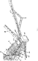
- FIG. 1 A multi-deck screening assembly in accordance with the present invention is illustrated in Figure 1 .
- the screening assembly comprises an elongate chassis 2 having mounted thereon a triple deck grading screen 4 comprising substantially parallel upper 6, intermediate 8 and lower 10 decks mounted on a frame 12 defined by a pair of substantially parallel side walls interconnected by transversely extending bridging members.
- Each of the upper, intermediate and lower screen decks 6,8,10 comprises a polyurethane screen having small openings or slots for water and/or undersize particles to pass through.
- the openings or slots in the upper deck 6 are larger than those of the intermediate deck 8, which are in turn larger than those of the lower deck 10.
- the frame 12 of the grading screen 4 is mounted on the chassis 2 via resilient mountings 14 and a vibration generating means 16, in the form of an eccentrically mounted motor driven rotor, is mounted on the frame 12 for imparting circular or reciprocating vibratory motion to the decks of the grading screen 4.
- Each deck 6,8,10 of the grading screen 4 has a downward slope from an upper receiving end to a lower discharge end at which over-sized material (relative to the screen deck concerned) can be discharged.
- Material of a size in excess of the size of the screening apertures of each screen deck is discharged under gravity action from the lower end of the respective deck 6,8,10 onto a respective stockpile conveyor 18,20,22, whereas under-sized material able to pass downwardly through the screening apertures of the respective screen deck 6,8,10 falls under gravity onto the deck below, where the further screening action takes place, or into a sump 24 in the case of the lower deck 10.
- a control panel 26 is mounted on one end of the chassis 2, adjacent a discharge end of the grading screen 4.
- Each of the stockpile conveyors 18,20,22 are located between control panel 26 and the grading screen 4.
- a first stockpile belt conveyor 18 is mounted on the chassis 2 arranged to receive over-sized material from the discharge end of the lower deck 10. The first stockpile conveyor 18 extends laterally from the chassis 2 to a first side of the chassis 2, substantially perpendicular to a longitudinal axis of the grading screen 4, a loading end of the first stockpile conveyor 18 being located directly beneath the discharge end of the lower deck 10 of the grading screen 4.
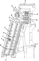
- a second stockpile conveyor 20 is mounted on the chassis 2 to receive over-sized material from the discharge end of the intermediate deck 8, via a first delivery chute 30 adapted to receive over-size material from the intermediate deck 8 of the grading screen 4.
- the second stockpile conveyor 20 extends laterally from the chassis 2, perpendicular to the grading screen 4, to a second side of the chassis 2, opposite said first side of the chassis 2, such that the second stockpile conveyor 20 extends parallel to and in an opposite direction to the first stockpile conveyor 18.
- a loading end of the second stockpile conveyor 20 is arranged alongside the loading end of the first stockpile conveyor 18 to receive material falling from the first delivery chute 30.
- a third stockpile conveyor 22 is arranged to receive over-sized material from the discharge end of the upper deck 6.
- a transfer belt conveyor 28 is provided adjacent the discharge end of the upper deck 6, said transfer conveyor 28 being arranged to deliver over-sized material from the discharge end of the upper deck 6 onto the third stockpile conveyor 22.
- the transfer conveyor 28 extends transverse to the chassis 2 and to the grading screen 4 and is located above the loading end of a second stockpile conveyor 20.
- the transfer conveyor 28 is arranged to deliver material from the discharge end of the upper deck 6 onto a loading end of the third stockpile conveyor 22, located to said one side of chassis 2 alongside the first stockpile conveyor 18, as best shown in Figure 5 .
- the third stockpile conveyor 22 may extend at an angle of approximately 45° to the first stockpile conveyor 18 and to the longitudinal axis of the chassis 2.
- the angle of the third stockpile conveyor 22 may be adjustable with respect to the chassis 2.
- the first, second and third stockpile conveyors 18,20,22 may be foldable against the sides of the chassis 2 for transportation and/or may be removable from the chassis 2 (in particular in the case of the third stockpile conveyor).
- a second delivery chute 32 is provided for transferring material from the discharge end of the upper deck 6 of the grading screen 4 onto the transfer conveyor 28, the second delivery chute 32 being mounted above and substantially parallel to the first delivery chute 30.
- first and second delivery chutes 30,32 and the transfer conveyor 28 are mounted on a carriage 34 slidable mounted on the chassis 2 via guide rails 36 for movement between an operative position, shown in Figure 4 , wherein the first chute 30 is aligned with the discharge end of the intermediate deck 8, and the second chute 32 is aligned with the discharge end of the upper deck 6, and a maintenance position, wherein the first chute 30 is spaced from the discharge end of the intermediate deck 8 and the second chute 32 is spaced from the discharge end of the upper deck 6, and wherein the transfer conveyor 28 is adjacent a rear side of the control panel 26.
Abstract
Description
- This invention relates to a multi-deck screen assembly, and in particular to a multi-deck screen assembly having three vertically spaced screen decks and to a compact discharge arrangement thereof.
- Vibrating screens are commonly used to sort, grade or classify particulate material, such as sand and aggregate.
- A typical vibrating screen comprises a frame, typically defined by a pair of substantially parallel side walls interconnected by transversely extending bridging members, upon which is mounted a polyurethane screen deck having small openings or slots for water and/or undersize particles to pass through.
- The frame is mounted on a chassis via resilient mountings and the frame, and thus the screen, is typically vibrated by means of a pair of counter rotating rotors defining eccentric masses driven by one or more drive motors, to impart circular or reciprocating vibratory motion to the screen. In a grading screen, the screen deck is typically arranged at a predetermined slope and material to be graded is delivered onto an upper end of the screen, typically entrained in a flow of water, particularly if they material is also being washed. The screen is vibrated at high frequency to convey the material over the screen deck and to cause undersize material (and water if present) to pass through the openings in the screen deck, oversize material being discharged from a lower end of the deck onto a stockpile conveyor or into a collection bay or hopper.
- It is known to provide a multi-deck screening assembly to produce a number of different grades of product. A plurality of screen decks, typically two or three decks, are typically arranged one above the other, and generally parallel to each other, each with a downward slope from an upper receiving end to a lower discharge end at which over-sized material (relative to the screen deck concerned) can be discharged. Material of a size in excess of the size of the screening apertures of each screen deck is discharged under gravity action from the lower end of the respective deck onto a respective stockpile conveyor, whereas under-sized material able to pass downwardly through the screening apertures of the respective screen deck falls under gravity onto the deck below, where the further screening action takes place, or into a collection region or sump in the case of the lowest deck. A triple deck screen assembly can grade feed material into four or more separate grades (particle size) of product.
- A problem with existing triple deck screen assemblies is how to arrange each of the stockpile conveyors within the dimensional constraints of the chassis while enabling over-sized material from each deck to be delivered onto a respective stockpile conveyor. Typically a first stockpile conveyor extends laterally from a first side of the chassis, transverse to the screening decks, for conveying oversized material from a lower deck, a second stockpile conveyor extending laterally from a second side of the chassis, opposite the first side, for conveying oversized material from an intermediate deck, typically via a intervening delivery chute, and a third stockpile conveyor extends from an end of the chassis, substantially perpendicular to the first and second stockpile conveyors and aligned with a longitudinal axis of the chassis, for conveying oversized material from an upper deck, typically via a intervening delivery chute. This arrangement increases the overall length of the screening assembly and also restricts access to the discharge end of each deck. As such, one or more of the stockpile conveyors and/or delivery chutes typically require removal to provided access to the discharge ends of the decks.
- According to the present invention there is provided A multi-deck screening assembly comprising a plurality of vertically stacked downwardly sloping screen decks, each screen deck having a plurality of grading apertures formed therethrough whereby under-sized material may pass through said apertures while over-sized material passes over a lower discharge end of each screen deck, said plurality of screen decks being mounted on a common frame, said frame being mounted on a chassis via resilient mounts and being provided with vibration generating means for imparting vibration to the screen decks, said plurality of screen decks comprising an upper deck, an intermediate deck mounted below the upper deck for receiving under-sized material from the upper deck, and a lower deck mounted below the intermediate deck for receiving under-sized material from the intermediate screen deck, a first stockpile conveyor being mounted on the chassis arranged to receive over-sized material from the discharge end of the lower deck, a second stockpile conveyor being mounted on the chassis to receive over-sized material from the discharge end of the intermediate deck, and a third stockpile conveyor being arranged to receive over-sized material from the discharge end of the upper deck, wherein a transfer conveyor is provided adjacent the discharge end of the upper deck, said transfer conveyor being arranged to deliver over-sized material from the discharge end of the upper deck onto the third stockpile conveyor.
- The transfer conveyor preferably extends transverse to the screen decks to discharge material onto the third stockpile to one side of the chassis. Preferably the transfer conveyor is mounted above a loading end of the second stockpile conveyor.
- A first delivery chute may be provided for transferring over-sized material from the discharge end of the upper deck onto the transfer conveyor. A second delivery chute may be provided for transferring over-sized material from the discharge end of the intermediate deck onto the second stockpile conveyor, the second delivery chute being mounted beneath and substantially parallel to the first delivery chute. Preferably said second delivery chute is mounted above a loading end of the first stockpile conveyor.
- In one embodiment the transfer conveyor and the first and second delivery chutes may be mounted on a carriage slidably mounted on the chassis for movement between a first position, wherein the first chute is aligned with the discharge end of the intermediate deck, and the second chute is aligned with the discharge end of the upper deck, and a second position, wherein the first chute is spaced from the discharge end of the intermediate deck and the second chute is spaced from the discharge end of the upper deck, to permit access to the discharge ends of the lower, intermediate and upper decks for maintenance when the carriage is in its second position. The carriage may be moveable in a direction substantially parallel to a longitudinal axis of the screen decks. The carriage may be mounted on guide rails or tracks provided on the chassis.
- In one embodiment a control panel may be mounted on an end of the chassis, said carriage being mounted between the discharge ends of the screen decks and the control panel.
- Preferably said first and second stockpile conveyors extend laterally from the chassis. Said first and second stockpile conveyors may extend from opposite sides of the chassis. Said first and second stockpile conveyors preferably extend parallel to one another. The third stockpile conveyor may be mounted on a side of the chassis adjacent the first stockpile conveyor.
- In one embodiment the third stockpile conveyor may be detachable from the chassis. Said first, second and third stockpile conveyors may comprise endless belt conveyors. The first and second stockpile conveyor may be foldable between outwardly extending operative positions and folded transport positions.
- A screening assembly in accordance with an embodiment of the present invention will now be described, by way of example only, with reference to the accompanying drawings, in which :-
-
Figure 1 is a perspective view of a screening apparatus in accordance with an embodiment of the present invention; -
Figure 2 is a detailed perspective view of the screening apparatus ofFigure 1 ; -
Figure 3 is a further detailed perspective view of the screening apparatus ofFigure 1 ; -
Figure 4 is a longitudinal sectional view of the screening apparatus ofFigure 1 ; and - Figure is a plan view of a portion of the screening apparatus of
Figure 1 . - A multi-deck screening assembly in accordance with the present invention is illustrated in
Figure 1 . The screening assembly comprises anelongate chassis 2 having mounted thereon a tripledeck grading screen 4 comprising substantially parallel upper 6, intermediate 8 and lower 10 decks mounted on aframe 12 defined by a pair of substantially parallel side walls interconnected by transversely extending bridging members. Each of the upper, intermediate andlower screen decks 6,8,10 comprises a polyurethane screen having small openings or slots for water and/or undersize particles to pass through. The openings or slots in the upper deck 6 are larger than those of the intermediate deck 8, which are in turn larger than those of thelower deck 10. - The
frame 12 of thegrading screen 4 is mounted on thechassis 2 viaresilient mountings 14 and a vibration generating means 16, in the form of an eccentrically mounted motor driven rotor, is mounted on theframe 12 for imparting circular or reciprocating vibratory motion to the decks of thegrading screen 4. - Each
deck 6,8,10 of thegrading screen 4 has a downward slope from an upper receiving end to a lower discharge end at which over-sized material (relative to the screen deck concerned) can be discharged. Material of a size in excess of the size of the screening apertures of each screen deck is discharged under gravity action from the lower end of therespective deck 6,8,10 onto arespective stockpile conveyor respective screen deck 6,8,10 falls under gravity onto the deck below, where the further screening action takes place, or into asump 24 in the case of thelower deck 10. - A
control panel 26 is mounted on one end of thechassis 2, adjacent a discharge end of thegrading screen 4. Each of thestockpile conveyors control panel 26 and thegrading screen 4. A firststockpile belt conveyor 18 is mounted on thechassis 2 arranged to receive over-sized material from the discharge end of thelower deck 10. Thefirst stockpile conveyor 18 extends laterally from thechassis 2 to a first side of thechassis 2, substantially perpendicular to a longitudinal axis of thegrading screen 4, a loading end of thefirst stockpile conveyor 18 being located directly beneath the discharge end of thelower deck 10 of thegrading screen 4. - A
second stockpile conveyor 20 is mounted on thechassis 2 to receive over-sized material from the discharge end of the intermediate deck 8, via afirst delivery chute 30 adapted to receive over-size material from the intermediate deck 8 of thegrading screen 4. Thesecond stockpile conveyor 20 extends laterally from thechassis 2, perpendicular to thegrading screen 4, to a second side of thechassis 2, opposite said first side of thechassis 2, such that thesecond stockpile conveyor 20 extends parallel to and in an opposite direction to thefirst stockpile conveyor 18. A loading end of thesecond stockpile conveyor 20 is arranged alongside the loading end of thefirst stockpile conveyor 18 to receive material falling from thefirst delivery chute 30. - A
third stockpile conveyor 22 is arranged to receive over-sized material from the discharge end of the upper deck 6. Atransfer belt conveyor 28 is provided adjacent the discharge end of the upper deck 6, saidtransfer conveyor 28 being arranged to deliver over-sized material from the discharge end of the upper deck 6 onto thethird stockpile conveyor 22. Thetransfer conveyor 28 extends transverse to thechassis 2 and to thegrading screen 4 and is located above the loading end of asecond stockpile conveyor 20. Thetransfer conveyor 28 is arranged to deliver material from the discharge end of the upper deck 6 onto a loading end of thethird stockpile conveyor 22, located to said one side ofchassis 2 alongside thefirst stockpile conveyor 18, as best shown inFigure 5 . - The
third stockpile conveyor 22 may extend at an angle of approximately 45° to thefirst stockpile conveyor 18 and to the longitudinal axis of thechassis 2. The angle of thethird stockpile conveyor 22 may be adjustable with respect to thechassis 2. - The first, second and
third stockpile conveyors chassis 2 for transportation and/or may be removable from the chassis 2 (in particular in the case of the third stockpile conveyor). - A
second delivery chute 32 is provided for transferring material from the discharge end of the upper deck 6 of thegrading screen 4 onto thetransfer conveyor 28, thesecond delivery chute 32 being mounted above and substantially parallel to thefirst delivery chute 30. - In order to facilitate access to the discharge ends of the intermediate and
lower decks 8,10 of thegrading screen 4, the first andsecond delivery chutes transfer conveyor 28 are mounted on acarriage 34 slidable mounted on thechassis 2 viaguide rails 36 for movement between an operative position, shown inFigure 4 , wherein thefirst chute 30 is aligned with the discharge end of the intermediate deck 8, and thesecond chute 32 is aligned with the discharge end of the upper deck 6, and a maintenance position, wherein thefirst chute 30 is spaced from the discharge end of the intermediate deck 8 and thesecond chute 32 is spaced from the discharge end of the upper deck 6, and wherein thetransfer conveyor 28 is adjacent a rear side of thecontrol panel 26. When thecarriage 34 is in its maintenance position, access is granted to the discharge ends of each of the lower 10, intermediate 8 and upper 6 decks of thegrading screen 4 for maintenance, for example to permit replacement the polyurethane screen mats of thegrading screen 4, without requiring substantial disassembly of the apparatus, as is typically required with prior art arrangements. - The compact arrangement of the first, second and
third stockpile conveyors transfer conveyor 28, enables a triple deck grading screen to take up the same footprint as that of a twin deck grading screen. - The invention is not limited to the embodiment(s) described herein but can be amended or modified without departing from the scope of the present invention.
Claims (15)
- A multi-deck screening assembly comprising a plurality of vertically stacked downwardly sloping screen decks (6,8,10), each screen deck having a plurality of grading apertures formed therethrough whereby under-sized material may pass through said apertures while over-sized material passes over a lower discharge end of each screen deck, said plurality of screen decks being mounted on a common frame (12), said frame (12) being mounted on a chassis (2) via resilient mounts (14) and being provided with vibration generating means (16) for imparting vibration to the screen decks, said plurality of screen decks comprising an upper deck (6), an intermediate deck (8) mounted below the upper deck for receiving under-sized material from the upper deck, and a lower deck (10) mounted below the intermediate deck for receiving under-sized material from the intermediate screen deck, a first stockpile conveyor (18) being mounted on the chassis (2) arranged to receive over-sized material from the discharge end of the lower deck (10), a second stockpile conveyor (20) being mounted on the chassis (2) to receive over-sized material from the discharge end of the intermediate deck (8), and a third stockpile conveyor (22) being arranged to receive over-sized material from the discharge end of the upper deck (6), wherein a transfer conveyor (28) is provided adjacent the discharge end of the upper deck (6), said transfer conveyor (28) being arranged to deliver over-sized material from the discharge end of the upper deck (6) onto the third stockpile conveyor (22).
- An assembly as claimed in claim 1, wherein the transfer conveyor (28) extends transverse to the screen decks (6,8,10) to discharge material onto the third stockpile (22) to one side of the chassis (2).
- An assembly as claimed in claim 2, wherein the transfer conveyor (28) is mounted above a loading end of the second stockpile conveyor (20).
- An assembly as claimed in any preceding claim, wherein a first delivery chute (32) is provided for transferring over-sized material from the discharge end of the upper deck (6) onto the transfer conveyor (32).
- An assembly as claimed in claim 4, wherein a second delivery chute (32) is provided for transferring over-sized material from the discharge end of the intermediate deck (8) onto the second stockpile conveyor (2), the second delivery chute (32) being mounted beneath the first delivery chute (30).
- An assembly as claimed in claim 5, wherein said second delivery chute (32) is mounted above a loading end of the first stockpile conveyor (18).
- An assembly as claimed in any claim 5 or claim 6, wherein the transfer conveyor (28) and the first and second delivery chutes (30,32) are mounted on a carriage (34) slidably mounted on the chassis (2) for movement between a first position, wherein the first delivery chute (30) is aligned with the discharge end of the intermediate deck (8), and the second delivery chute (32) is aligned with the discharge end of the upper deck (6), and a second position, wherein the first delivery chute (30) is spaced from the discharge end of the intermediate deck (10) and the second delivery chute (32) is spaced from the discharge end of the upper deck (6), to permit access to the discharge ends of the lower, intermediate and upper decks (6,8,10) for maintenance when the carriage (34) is in its second position.
- An assembly as claimed in claim 7, wherein said carriage (34) is moveable in a direction substantially parallel to a longitudinal axis of the screen decks (6,8,10).
- An assembly as claimed in claim 8, wherein a control panel (26) is mounted on an end of the chassis (2), said carriage (34) being mounted between the discharge ends of the screen decks (6,8,10) and the control panel (26).
- An assembly as claimed in any preceding claim, wherein said first and second stockpile conveyors (18,20) extend laterally from the chassis (2).
- An assembly as claimed in claim 10, wherein the first and second stockpile conveyors (18,20) extend from opposite sides of the chassis (2).
- An assembly as claimed in claim 10 or claim 11, wherein the third stockpile conveyor (22) is mounted on a side of the chassis (2) adjacent the first stockpile conveyor (18).
- An assembly as claimed in any preceding claim, wherein the third stockpile conveyor (22) is detachable from the chassis (2).
- An assembly as claimed in any preceding claim, wherein said first, second and third stockpile conveyors (18,20,22) comprise endless belt conveyors.
- An assembly as claimed in any preceding claim, wherein said first and second stockpile conveyor (18,20) are foldable between outwardly extending operative positions and folded transport positions.
Applications Claiming Priority (1)
| Application Number | Priority Date | Filing Date | Title |
|---|---|---|---|
| GB1501982.1A GB2523658B (en) | 2015-02-06 | 2015-02-06 | A multi-deck screening assembly |
Publications (3)
| Publication Number | Publication Date |
|---|---|
| EP3061533A2 true EP3061533A2 (en) | 2016-08-31 |
| EP3061533A3 EP3061533A3 (en) | 2016-11-16 |
| EP3061533B1 EP3061533B1 (en) | 2023-03-08 |
Family
ID=52746231
Family Applications (1)
| Application Number | Title | Priority Date | Filing Date |
|---|---|---|---|
| EP16154404.4A Active EP3061533B1 (en) | 2015-02-06 | 2016-02-05 | Multi-deck screening assembly |
Country Status (3)
| Country | Link |
|---|---|
| US (1) | US9776214B2 (en) |
| EP (1) | EP3061533B1 (en) |
| GB (1) | GB2523658B (en) |
Cited By (1)
| Publication number | Priority date | Publication date | Assignee | Title |
|---|---|---|---|---|
| EP3482836A1 (en) | 2017-11-13 | 2019-05-15 | Sandvik Intellectual Property AB | Screening assembly and mobile material processing machine |
Families Citing this family (22)
| Publication number | Priority date | Publication date | Assignee | Title |
|---|---|---|---|---|
| GB2548856B (en) | 2016-03-30 | 2018-03-21 | Cde Global Ltd | Apparatus for processing aggregate material |
| GB2550943A (en) * | 2016-06-01 | 2017-12-06 | Cde Global Ltd | A Multi-deck screening assembly |
| DE202016004740U1 (en) * | 2016-08-04 | 2017-11-07 | Klöckner Siebmaschinen GmbH & Co. KG | Multi-stage screening device and screening stage for it |
| GB2559360B (en) * | 2017-02-01 | 2019-10-23 | Cde Global Ltd | Apparatus for washing and grading aggregate |
| GB2560038B (en) | 2017-02-28 | 2020-09-09 | Cde Global Ltd | Method and apparatus for washing and grading sand and aggregate |
| GB2560517B (en) | 2017-03-13 | 2019-04-24 | Cde Global Ltd | Apparatus for washing and grading sand and aggregate |
| EP3621751A2 (en) * | 2017-05-11 | 2020-03-18 | ISMECA Semiconductor Holding SA | Feeder assembly |
| US10357779B2 (en) * | 2017-05-25 | 2019-07-23 | Thomas Pratt | Method for sorting soil |
| CN108704852A (en) * | 2018-07-12 | 2018-10-26 | 河南省振源科技有限公司 | Building stones produce three sections of sieve classification systems and its sieve classification method |
| WO2020047131A1 (en) * | 2018-08-28 | 2020-03-05 | Superior Industries, Inc. | Aggregate processing systems, methods and apparatus |
| DE102019120580B4 (en) * | 2019-07-30 | 2021-04-01 | Kleemann Gmbh | Rock processing machine |
| CN110586448A (en) * | 2019-08-27 | 2019-12-20 | 湖北民族大学 | Chinese yam and plant separating screen |
| DE102019126778A1 (en) * | 2019-10-04 | 2021-04-08 | Kleemann Gmbh | Rock processing plant |
| AT523535B1 (en) * | 2020-04-16 | 2021-09-15 | Neuson Hydrotec Gmbh | Mobile classifying or sieving device |
| FI20205524A1 (en) * | 2020-05-25 | 2021-11-26 | Metso Minerals Inc | Screen tightening in mobile multi-deck screening devices |
| CN111632841A (en) * | 2020-06-04 | 2020-09-08 | 钱学森 | Screening device for agricultural planting seeds |
| GB2597327B (en) * | 2020-07-20 | 2022-12-21 | Terex Gb Ltd | Material Washing System and Apparatus |
| CA3215892A1 (en) * | 2021-04-26 | 2022-11-03 | Jasvinder SHARMA | Dividing hopper and transportable screening apparatus |
| GB2609224B (en) | 2021-07-23 | 2023-08-02 | Cde Global Ltd | Apparatus for processing aggregate material |
| CN114178167A (en) * | 2021-10-29 | 2022-03-15 | 扬州正大机械制造有限公司 | Dustless screening lifting machine of likepowder thing |
| CN116140207A (en) * | 2021-11-23 | 2023-05-23 | 湖南省宝庆农产品进出口有限公司 | Automatic vibrating feeder for lily |
| CN114772158B (en) * | 2022-06-21 | 2022-08-23 | 山东丸美佳食品有限公司 | Fish bean curd conveyor |
Family Cites Families (15)
| Publication number | Priority date | Publication date | Assignee | Title |
|---|---|---|---|---|
| DE7407300U (en) | 1974-06-20 | Allgaier Werke Gmbh | Vibrating screening machine with a large, rectangular screen structure | |
| US2276333A (en) * | 1939-12-14 | 1942-03-17 | Pioneer Engineering Works Inc | Apparatus and method for crushing and segregating materials |
| US3647150A (en) | 1969-08-27 | 1972-03-07 | Pettibone Corp | Crusher |
| US4598875A (en) * | 1978-09-11 | 1986-07-08 | Allis-Chalmers Corporation | Portable crushing and screening plant |
| US5234564A (en) * | 1992-07-24 | 1993-08-10 | Smith Roger G | Mobile screen assembly for rubble and debris |
| US5341939A (en) * | 1993-02-22 | 1994-08-30 | Corrosion Engineering, Inc. | Multiple deck vibrating screen apparatus |
| BE1010451A6 (en) * | 1996-08-02 | 1998-08-04 | Brecon Nv | Sieve machine |
| ATE282481T1 (en) * | 1999-01-21 | 2004-12-15 | Extec Screens & Crushers Ltd | SCREENING DEVICE |
| US6698594B2 (en) * | 2002-03-18 | 2004-03-02 | Ohio Central Steel Company | Screening machine |
| US6935587B2 (en) * | 2002-06-06 | 2005-08-30 | Johnson Crushers International | Mobile rock crushing plant |
| CN101384378A (en) * | 2006-02-16 | 2009-03-11 | 奥贾伊研究与设计有限公司 | A material screening apparatus |
| US20150103614A1 (en) * | 2009-01-28 | 2015-04-16 | Astec, Inc. | Apparatus and method for a concrete plant |
| EP2822707B1 (en) * | 2012-03-09 | 2022-06-22 | AAA Screens Pty Ltd | A mobile screening apparatus |
| US9205459B2 (en) * | 2012-08-28 | 2015-12-08 | Terex Usa, Llc | Vibrating screen deck deflector systems and methods |
| US9146554B2 (en) | 2012-10-16 | 2015-09-29 | Adam Hoban | Aggregate processing control system |
-
2015
- 2015-02-06 GB GB1501982.1A patent/GB2523658B/en active Active
-
2016
- 2016-02-04 US US15/015,701 patent/US9776214B2/en active Active
- 2016-02-05 EP EP16154404.4A patent/EP3061533B1/en active Active
Non-Patent Citations (1)
| Title |
|---|
| None * |
Cited By (6)
| Publication number | Priority date | Publication date | Assignee | Title |
|---|---|---|---|---|
| EP3482836A1 (en) | 2017-11-13 | 2019-05-15 | Sandvik Intellectual Property AB | Screening assembly and mobile material processing machine |
| WO2019092243A1 (en) | 2017-11-13 | 2019-05-16 | Sandvik Intellectual Property Ab | Screening assembly and mobile material processing machine |
| EP3482836B1 (en) | 2017-11-13 | 2020-06-17 | Sandvik Intellectual Property AB | Screening assembly and mobile material processing machine |
| CN111344071A (en) * | 2017-11-13 | 2020-06-26 | 山特维克知识产权股份有限公司 | Screen assembly and mobile material processor |
| CN111344071B (en) * | 2017-11-13 | 2022-09-20 | 山特维克知识产权股份有限公司 | Screen assembly and mobile material processor |
| US11511319B2 (en) | 2017-11-13 | 2022-11-29 | Sandvik Intellectual Property Ab | Screening assembly and mobile material processing machine |
Also Published As
| Publication number | Publication date |
|---|---|
| GB2523658A (en) | 2015-09-02 |
| US9776214B2 (en) | 2017-10-03 |
| EP3061533A3 (en) | 2016-11-16 |
| US20160228919A1 (en) | 2016-08-11 |
| GB201501982D0 (en) | 2015-03-25 |
| EP3061533B1 (en) | 2023-03-08 |
| GB2523658B (en) | 2019-10-30 |
Similar Documents
| Publication | Publication Date | Title |
|---|---|---|
| EP3061533B1 (en) | Multi-deck screening assembly | |
| US6889846B2 (en) | Hybrid screen | |
| EP3251759B1 (en) | A multi-deck screening assembly | |
| AU2018201257B2 (en) | Method and apparatus for washing and grading sand and aggregate | |
| EP2910313B1 (en) | Screen assembly | |
| US10189028B2 (en) | Method and apparatus for washing and grading aggregate | |
| AU2019245933B2 (en) | Apparatus for grading and washing sand | |
| GB2528257A (en) | Apparatus for grading and blending aggregates | |
| US5904254A (en) | Vibratory particle separating apparatus | |
| US3087618A (en) | Device for separating fine from coarse materials | |
| CN209968929U (en) | Multistage sorter of beans | |
| JP3690363B2 (en) | Raw material particle size separation method and separation apparatus | |
| CN215150766U (en) | Quick screening device for high-speed mixer | |
| JP2003300019A (en) | Vibration screen and screen equipment provided with the same | |
| CN110090801B (en) | Bean multistage sorting machine | |
| CN218796393U (en) | Multifunctional screening system | |
| DE4434748C2 (en) | Method and device for separating a bulk material mixture | |
| CN215878706U (en) | Filter equipment is used in loading and unloading of mechanism sand | |
| EP4059622A1 (en) | Screen apparatus with multi-discharge | |
| US1201685A (en) | Method of and apparatus for handling coal. | |
| CS259146B1 (en) | Equipment for loose materials' vibrating feed and sorting |
Legal Events
| Date | Code | Title | Description |
|---|---|---|---|
| PUAI | Public reference made under article 153(3) epc to a published international application that has entered the european phase |
Free format text: ORIGINAL CODE: 0009012 |
|
| AK | Designated contracting states |
Kind code of ref document: A2 Designated state(s): AL AT BE BG CH CY CZ DE DK EE ES FI FR GB GR HR HU IE IS IT LI LT LU LV MC MK MT NL NO PL PT RO RS SE SI SK SM TR |
|
| AX | Request for extension of the european patent |
Extension state: BA ME |
|
| PUAL | Search report despatched |
Free format text: ORIGINAL CODE: 0009013 |
|
| AK | Designated contracting states |
Kind code of ref document: A3 Designated state(s): AL AT BE BG CH CY CZ DE DK EE ES FI FR GB GR HR HU IE IS IT LI LT LU LV MC MK MT NL NO PL PT RO RS SE SI SK SM TR |
|
| AX | Request for extension of the european patent |
Extension state: BA ME |
|
| RIC1 | Information provided on ipc code assigned before grant |
Ipc: B65G 69/12 20060101ALI20161012BHEP Ipc: B07B 13/16 20060101ALI20161012BHEP Ipc: B65G 47/18 20060101ALI20161012BHEP Ipc: B07B 1/00 20060101ALI20161012BHEP Ipc: B65G 47/44 20060101ALI20161012BHEP Ipc: B65G 47/20 20060101ALI20161012BHEP Ipc: B07B 1/40 20060101AFI20161012BHEP |
|
| STAA | Information on the status of an ep patent application or granted ep patent |
Free format text: STATUS: REQUEST FOR EXAMINATION WAS MADE |
|
| 17P | Request for examination filed |
Effective date: 20170421 |
|
| RBV | Designated contracting states (corrected) |
Designated state(s): AL AT BE BG CH CY CZ DE DK EE ES FI FR GB GR HR HU IE IS IT LI LT LU LV MC MK MT NL NO PL PT RO RS SE SI SK SM TR |
|
| STAA | Information on the status of an ep patent application or granted ep patent |
Free format text: STATUS: EXAMINATION IS IN PROGRESS |
|
| STAA | Information on the status of an ep patent application or granted ep patent |
Free format text: STATUS: EXAMINATION IS IN PROGRESS |
|
| 17Q | First examination report despatched |
Effective date: 20201007 |
|
| STAA | Information on the status of an ep patent application or granted ep patent |
Free format text: STATUS: EXAMINATION IS IN PROGRESS |
|
| RBV | Designated contracting states (corrected) |
Designated state(s): AL AT BE BG CH CY CZ DE DK EE ES FI FR GR HR HU IE IS IT LI LT LU LV MC MK MT NL NO PL PT RO RS SE SI SK SM TR |
|
| GRAP | Despatch of communication of intention to grant a patent |
Free format text: ORIGINAL CODE: EPIDOSNIGR1 |
|
| STAA | Information on the status of an ep patent application or granted ep patent |
Free format text: STATUS: GRANT OF PATENT IS INTENDED |
|
| INTG | Intention to grant announced |
Effective date: 20221104 |
|
| GRAS | Grant fee paid |
Free format text: ORIGINAL CODE: EPIDOSNIGR3 |
|
| GRAA | (expected) grant |
Free format text: ORIGINAL CODE: 0009210 |
|
| STAA | Information on the status of an ep patent application or granted ep patent |
Free format text: STATUS: THE PATENT HAS BEEN GRANTED |
|
| AK | Designated contracting states |
Kind code of ref document: B1 Designated state(s): AL AT BE BG CH CY CZ DE DK EE ES FI FR GR HR HU IE IS IT LI LT LU LV MC MK MT NL NO PL PT RO RS SE SI SK SM TR |
|
| REG | Reference to a national code |
Ref country code: CH Ref legal event code: EP Ref country code: AT Ref legal event code: REF Ref document number: 1552222 Country of ref document: AT Kind code of ref document: T Effective date: 20230315 |
|
| REG | Reference to a national code |
Ref country code: DE Ref legal event code: R096 Ref document number: 602016078156 Country of ref document: DE |
|
| REG | Reference to a national code |
Ref country code: IE Ref legal event code: FG4D |
|
| REG | Reference to a national code |
Ref country code: LT Ref legal event code: MG9D |
|
| P01 | Opt-out of the competence of the unified patent court (upc) registered |
Effective date: 20230530 |
|
| REG | Reference to a national code |
Ref country code: NL Ref legal event code: MP Effective date: 20230308 |
|
| PG25 | Lapsed in a contracting state [announced via postgrant information from national office to epo] |
Ref country code: RS Free format text: LAPSE BECAUSE OF FAILURE TO SUBMIT A TRANSLATION OF THE DESCRIPTION OR TO PAY THE FEE WITHIN THE PRESCRIBED TIME-LIMIT Effective date: 20230308 Ref country code: NO Free format text: LAPSE BECAUSE OF FAILURE TO SUBMIT A TRANSLATION OF THE DESCRIPTION OR TO PAY THE FEE WITHIN THE PRESCRIBED TIME-LIMIT Effective date: 20230608 Ref country code: LV Free format text: LAPSE BECAUSE OF FAILURE TO SUBMIT A TRANSLATION OF THE DESCRIPTION OR TO PAY THE FEE WITHIN THE PRESCRIBED TIME-LIMIT Effective date: 20230308 Ref country code: LT Free format text: LAPSE BECAUSE OF FAILURE TO SUBMIT A TRANSLATION OF THE DESCRIPTION OR TO PAY THE FEE WITHIN THE PRESCRIBED TIME-LIMIT Effective date: 20230308 Ref country code: HR Free format text: LAPSE BECAUSE OF FAILURE TO SUBMIT A TRANSLATION OF THE DESCRIPTION OR TO PAY THE FEE WITHIN THE PRESCRIBED TIME-LIMIT Effective date: 20230308 Ref country code: ES Free format text: LAPSE BECAUSE OF FAILURE TO SUBMIT A TRANSLATION OF THE DESCRIPTION OR TO PAY THE FEE WITHIN THE PRESCRIBED TIME-LIMIT Effective date: 20230308 |
|
| REG | Reference to a national code |
Ref country code: AT Ref legal event code: MK05 Ref document number: 1552222 Country of ref document: AT Kind code of ref document: T Effective date: 20230308 |
|
| PG25 | Lapsed in a contracting state [announced via postgrant information from national office to epo] |
Ref country code: SE Free format text: LAPSE BECAUSE OF FAILURE TO SUBMIT A TRANSLATION OF THE DESCRIPTION OR TO PAY THE FEE WITHIN THE PRESCRIBED TIME-LIMIT Effective date: 20230308 Ref country code: NL Free format text: LAPSE BECAUSE OF FAILURE TO SUBMIT A TRANSLATION OF THE DESCRIPTION OR TO PAY THE FEE WITHIN THE PRESCRIBED TIME-LIMIT Effective date: 20230308 Ref country code: GR Free format text: LAPSE BECAUSE OF FAILURE TO SUBMIT A TRANSLATION OF THE DESCRIPTION OR TO PAY THE FEE WITHIN THE PRESCRIBED TIME-LIMIT Effective date: 20230609 Ref country code: FI Free format text: LAPSE BECAUSE OF FAILURE TO SUBMIT A TRANSLATION OF THE DESCRIPTION OR TO PAY THE FEE WITHIN THE PRESCRIBED TIME-LIMIT Effective date: 20230308 |
|
| PG25 | Lapsed in a contracting state [announced via postgrant information from national office to epo] |
Ref country code: SM Free format text: LAPSE BECAUSE OF FAILURE TO SUBMIT A TRANSLATION OF THE DESCRIPTION OR TO PAY THE FEE WITHIN THE PRESCRIBED TIME-LIMIT Effective date: 20230308 Ref country code: RO Free format text: LAPSE BECAUSE OF FAILURE TO SUBMIT A TRANSLATION OF THE DESCRIPTION OR TO PAY THE FEE WITHIN THE PRESCRIBED TIME-LIMIT Effective date: 20230308 Ref country code: PT Free format text: LAPSE BECAUSE OF FAILURE TO SUBMIT A TRANSLATION OF THE DESCRIPTION OR TO PAY THE FEE WITHIN THE PRESCRIBED TIME-LIMIT Effective date: 20230710 Ref country code: EE Free format text: LAPSE BECAUSE OF FAILURE TO SUBMIT A TRANSLATION OF THE DESCRIPTION OR TO PAY THE FEE WITHIN THE PRESCRIBED TIME-LIMIT Effective date: 20230308 Ref country code: CZ Free format text: LAPSE BECAUSE OF FAILURE TO SUBMIT A TRANSLATION OF THE DESCRIPTION OR TO PAY THE FEE WITHIN THE PRESCRIBED TIME-LIMIT Effective date: 20230308 Ref country code: AT Free format text: LAPSE BECAUSE OF FAILURE TO SUBMIT A TRANSLATION OF THE DESCRIPTION OR TO PAY THE FEE WITHIN THE PRESCRIBED TIME-LIMIT Effective date: 20230308 |
|
| PG25 | Lapsed in a contracting state [announced via postgrant information from national office to epo] |
Ref country code: SK Free format text: LAPSE BECAUSE OF FAILURE TO SUBMIT A TRANSLATION OF THE DESCRIPTION OR TO PAY THE FEE WITHIN THE PRESCRIBED TIME-LIMIT Effective date: 20230308 Ref country code: PL Free format text: LAPSE BECAUSE OF FAILURE TO SUBMIT A TRANSLATION OF THE DESCRIPTION OR TO PAY THE FEE WITHIN THE PRESCRIBED TIME-LIMIT Effective date: 20230308 Ref country code: IS Free format text: LAPSE BECAUSE OF FAILURE TO SUBMIT A TRANSLATION OF THE DESCRIPTION OR TO PAY THE FEE WITHIN THE PRESCRIBED TIME-LIMIT Effective date: 20230708 |
|
| REG | Reference to a national code |
Ref country code: DE Ref legal event code: R097 Ref document number: 602016078156 Country of ref document: DE |
|
| PLBE | No opposition filed within time limit |
Free format text: ORIGINAL CODE: 0009261 |
|
| STAA | Information on the status of an ep patent application or granted ep patent |
Free format text: STATUS: NO OPPOSITION FILED WITHIN TIME LIMIT |
|
| PG25 | Lapsed in a contracting state [announced via postgrant information from national office to epo] |
Ref country code: SI Free format text: LAPSE BECAUSE OF FAILURE TO SUBMIT A TRANSLATION OF THE DESCRIPTION OR TO PAY THE FEE WITHIN THE PRESCRIBED TIME-LIMIT Effective date: 20230308 Ref country code: DK Free format text: LAPSE BECAUSE OF FAILURE TO SUBMIT A TRANSLATION OF THE DESCRIPTION OR TO PAY THE FEE WITHIN THE PRESCRIBED TIME-LIMIT Effective date: 20230308 |
|
| 26N | No opposition filed |
Effective date: 20231211 |