EP3061366A1 - Conversion lifting platform - Google Patents
Conversion lifting platform Download PDFInfo
- Publication number
- EP3061366A1 EP3061366A1 EP15197466.4A EP15197466A EP3061366A1 EP 3061366 A1 EP3061366 A1 EP 3061366A1 EP 15197466 A EP15197466 A EP 15197466A EP 3061366 A1 EP3061366 A1 EP 3061366A1
- Authority
- EP
- European Patent Office
- Prior art keywords
- checkout
- module
- housing
- rotatable platform
- gear
- Prior art date
- Legal status (The legal status is an assumption and is not a legal conclusion. Google has not performed a legal analysis and makes no representation as to the accuracy of the status listed.)
- Granted
Links
Images



Classifications
-
- A—HUMAN NECESSITIES
- A47—FURNITURE; DOMESTIC ARTICLES OR APPLIANCES; COFFEE MILLS; SPICE MILLS; SUCTION CLEANERS IN GENERAL
- A47F—SPECIAL FURNITURE, FITTINGS, OR ACCESSORIES FOR SHOPS, STOREHOUSES, BARS, RESTAURANTS OR THE LIKE; PAYING COUNTERS
- A47F9/00—Shop, bar, bank or like counters
- A47F9/02—Paying counters
- A47F9/04—Check-out counters, e.g. for self-service stores
-
- G—PHYSICS
- G07—CHECKING-DEVICES
- G07G—REGISTERING THE RECEIPT OF CASH, VALUABLES, OR TOKENS
- G07G1/00—Cash registers
- G07G1/0018—Constructional details, e.g. of drawer, printing means, input means
-
- A—HUMAN NECESSITIES
- A47—FURNITURE; DOMESTIC ARTICLES OR APPLIANCES; COFFEE MILLS; SPICE MILLS; SUCTION CLEANERS IN GENERAL
- A47F—SPECIAL FURNITURE, FITTINGS, OR ACCESSORIES FOR SHOPS, STOREHOUSES, BARS, RESTAURANTS OR THE LIKE; PAYING COUNTERS
- A47F9/00—Shop, bar, bank or like counters
- A47F9/02—Paying counters
- A47F9/04—Check-out counters, e.g. for self-service stores
- A47F9/046—Arrangement of recording means in or on check-out counters
-
- A—HUMAN NECESSITIES
- A47—FURNITURE; DOMESTIC ARTICLES OR APPLIANCES; COFFEE MILLS; SPICE MILLS; SUCTION CLEANERS IN GENERAL
- A47F—SPECIAL FURNITURE, FITTINGS, OR ACCESSORIES FOR SHOPS, STOREHOUSES, BARS, RESTAURANTS OR THE LIKE; PAYING COUNTERS
- A47F10/00—Furniture or installations specially adapted to particular types of service systems, not otherwise provided for
- A47F10/02—Furniture or installations specially adapted to particular types of service systems, not otherwise provided for for self-service type systems, e.g. supermarkets
-
- F—MECHANICAL ENGINEERING; LIGHTING; HEATING; WEAPONS; BLASTING
- F16—ENGINEERING ELEMENTS AND UNITS; GENERAL MEASURES FOR PRODUCING AND MAINTAINING EFFECTIVE FUNCTIONING OF MACHINES OR INSTALLATIONS; THERMAL INSULATION IN GENERAL
- F16H—GEARING
- F16H19/00—Gearings comprising essentially only toothed gears or friction members and not capable of conveying indefinitely-continuing rotary motion
- F16H19/02—Gearings comprising essentially only toothed gears or friction members and not capable of conveying indefinitely-continuing rotary motion for interconverting rotary or oscillating motion and reciprocating motion
- F16H19/04—Gearings comprising essentially only toothed gears or friction members and not capable of conveying indefinitely-continuing rotary motion for interconverting rotary or oscillating motion and reciprocating motion comprising a rack
-
- G—PHYSICS
- G07—CHECKING-DEVICES
- G07G—REGISTERING THE RECEIPT OF CASH, VALUABLES, OR TOKENS
- G07G1/00—Cash registers
- G07G1/12—Cash registers electronically operated
Definitions
- the kiosks come in a variety of sizes and are used for a variety of purposes. Some kiosks are drive through, such as fast food establishments, pharmacies, banks, and the like. Other kiosks are stationary located in gas stations, grocery stores, department stores, and the like.
- self-checkout kiosks are the victim of their own success because the popularity has been so well received the traditional model and the self-checkout kiosks may become a bottleneck in stores during heavy customer demand periods.
- a device includes a housing, a rotatable platform, and a lift assembly supported by the housing and coupled to lift the rotatable platform above a working surface of the housing, the rotatable platform configured to support a checkout module and rotate the checkout module between a self-checkout position and an assisted checkout position.
- a system includes a housing, a checkout module having a product identifier, a rotatable platform configured to support and rotate the checkout module, and a lift assembly supported by the housing and coupled to lift the rotatable platform above the housing such that the checkout module is rotatable between a self-checkout position and an assisted checkout position when lowered back to the housing.
- a method includes receiving force to rotate a gear to raise a platform containing a checkout module above a surface of a housing, receiving force to rotate the platform to place the checkout module into a self-checkout orientation or an assisted checkout orientation, and receiving force to lower the platform containing the checkout module such that the module and housing operate in a self-checkout mode or an assisted checkout mode.
- a device comprising: a housing; a rotatable platform; a lift assembly supported by the housing and coupled to lift the rotatable platform above a working surface of the housing, the rotatable platform being configured to support a checkout module and rotate the checkout module between a self-checkout position and an assisted checkout position.
- a method comprising: rotating a gear to raise a platform containing a checkout module above a surface of a housing; rotating the platform to place the checkout module into a self-checkout orientation or an assisted checkout orientation; and lowering the platform containing the checkout module such that the module and housing operate in a self-checkout mode or an assisted checkout mode.
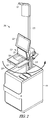
- FIG. 1 is a block perspective diagram of a system 100 that includes a housing 110 supporting a checkout module indicated generally at 115.
- Housing 110 may have a rack like structure and may contain circuitry to provide power, processing, circuitry, card reading and other functions.
- the checkout module includes a product identifier, such as one or more product identifiers, such as RF readers or barcode scanners 120, 121, and a display device 125, which may be a touchscreen type of display device for accepting user input.
- Scanner 120 is shown as parallel to a working surface 127 of the housing 110 to facilitate scanning of products to be purchased.
- the working surface may also be referred to as a top surface.
- the module 115 may alternatively include customer card readers for completing transactions as opposed to including card readers in a rack in housing 110.
- a marker device 130 may be used to provide indicators to customers, such as via a light 135 having a color representative of a status of a lane that the system is servicing.
- System 100 may be used in two different modes.
- a customer self-service mode wherein the customer scans products the customer is purchasing, or in an assisted mode, where a cashier scans the customer's products and performs other checkout functions.
- the modes may be changed by the cashier by lifting the module 115 as indicated by arrow 140, and rotating it 180 degrees such that the scanners and display are facing opposite the position shown in FIG. 1 .
- Such a changing enables the flow of customer traffic to remain the same in both modes, but facilitates changing the party handling the scanning.
- cashiers are much more proficient at scanning products, having practiced doing so many more hours than an average customer. Changing the mode of operation thus provides a store the option of configuring systems in either mode to facilitate efficient customer flow and reduce bottlenecks which may be caused by customer self-checkout during busy periods.
- module 115 may weigh more than is conveniently lifted by cashiers and other store personnel. Typical modules today weigh nearly 40 Kg. Prior methods of reversing modes involved sliding the module out of the rack and using separate equipment to rotate it and slide it back into the rack.
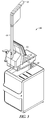
- FIG. 2 is a block perspective diagram of system 100 illustrating the module 115 lifted above the top surface 127 of the housing 110 as indicating generally at 200.
- the lift travel may be about 7 inches (177.8mm) in one embodiment, but may vary depending on the size of the module to be reconfigured.
- a lifting arm 210 is coupled to a rotatable platform 215, both of which are shown in further detail below. Once the module is lifted, the platform 215 supports the module above the surface 127 of the housing and allows rotation as indicated by arrow 220.
- FIG. 1 shows the system 100 in two different modes of operation, a customer self-checkout mode indicated at 100 or 400, and in a customer assisted mode indicated at 400 or 100 respectively.
- the direction of the module combined with designed customer traffic patterns in a store may define which mode the system is in.
- FIG. 5 is a pseudo exploded perspective block diagram view of a lift assembly 500, also referred to as a lifting assembly.
- the lifting assembly 500 is shown fully assembled, but selected parts are duplicated and separately illustrated to more clearly illustrate the assembled lifting assembly 500.
- the lifting mechanism 500 includes a rotatable platform 510.
- the lifting mechanism 500 is supported by the housing and coupled to lift the rotatable platform 510 above the housing.
- the rotatable platform 510 configured to support a checkout module and rotate the checkout module between a self-checkout position and an assisted checkout position as illustrated by arrow 512.
- a bearing 515 may be used to provide for rotation of the rotatable platform and the platform and bearing 515 are structurally formed to support typical module weights and securely hold the module during rotation.
- a spring 520 is coupled to the lift assembly to act as a counter balance to aid in lifting the rotatable platform with self-checkout module.
- the spring 520 may be a gas spring, such as one rated at 80 lbs (36.3 kg) in one embodiment, corresponding to slightly less than the weight of the module and lift assembly combined.
- the lift assembly 500 may also include at least one gear rack 525 (two shown) coupled to an upright support arm 530.
- the upright support arm may include C-shaped rails (PCB Linear CR30 Rail, 400 mm long, Part Number CR30R400 for example) with crown rollers mounted in linear rail slide blocks (4 blocks - PCB Linear CR30 Slide, Part Number CRSS30MCA for example) to provide a telescoping mount for the rotatable platform that is driven up and down by the gear racks 525.
- the direction of telescoping is illustrated by arrow 535.
- a worm drive 540 supported by housing 110 may have one or more spur gears 545 to mesh with the gear rack 525.
- An example gear rack may have a height of 0.720 inches (18.300mm), width of 0.750 inches (19.050mm) and length of 8 inches (203.2 mm), with a 20 degree pressure angle, pitch 16 and may be formed of machinable carbon steel or other suitable material.
- the spur gears have 36 teeth, a 20 degree pressure angle, a 16 pitch, and are formed of machinable carbon steel or other suitable material.
- Various other gears having different numbers of teeth, angles and pitch may be used in further embodiments.
- Rotation of the worm drive such as by a user utilizing a hand gear 550 coupled to the worm drive 540 is used to move the platform up and down, altogether providing an 18:1 ratio gear drive in one embodiment.
- Other ratios may be used in further embodiments such as may be desired based on ergonomic factors.
- the platform may be configured to stop downward motion when flush with the top surface 127 of the housing 110, and the weight of the module will keep the module from lifting without force applied by a user to the worm drive.
- the hand gear may include a handle 555 to rotate the hand gear.
- FIG. 6 is a block rear elevation representation of the system at 600.
- System 600 includes a housing 610, which may include various electronics 615 for interfacing with a checkout module 620 via an electrical connector 625.
- connector 625 is an electrical connector cable coupled between the checkout module 620 and the housing 610.
- the electrical connector cable 625 may contain sufficient slack to allow lifting and rotation of the checkout module 620 between the self-checkout position and the assisted checkout position.
- rotation of the module 620 may be limited in one direction to 180 degrees by two sets of 90 degree circular slots in the lift and rotating platforms and a plate in between with studs and bushings in a specific arrangement.
- the combination of rotating platforms and plate act as a bearing mechanism for rotation.
- Ultra High Molecular Weight plastic may be used to overcome the friction instead of ball bearings or other type of bearing.
- a computing device 630 as described in further detail may also be included either in the module 620, housing 610, or both.
- the functions or algorithms utilized to scan products, perform checkout transactions, and communicate with other computers such as remote servers, may be implemented in software or a combination of software and human implemented procedures in one embodiment.
- the software may consist of computer executable instructions stored on computer readable media or computer readable storage device such as one or more memory or other type of hardware based storage devices, either local or networked. Further, such functions correspond to modules, which are software, hardware, firmware or any combination thereof. Multiple functions may be performed in one or more modules as desired, and the embodiments described are merely examples.
- the software may be executed on a digital signal processor, ASIC, microprocessor, or other type of processor operating on a computer system, such as a personal computer, server or other computer system.
- FIG. 7 is a simplified block diagram of a checkout module 700 according to an example embodiment.
- the scanner 700 includes one or more computing devices such as programmed processors that are specifically configured to perform processing associated with scanning products and obtaining payment information to perform customer checkout.
- the module 700 may include a variety of other hardware components, such as network adapters, memory, display screen, input mechanisms, and the like.
- the module 700 includes an entry mechanism 701 and a communication mechanism 702. Each of these and their interactions with one another will now be discussed in turn.
- the entry mechanism 701 can include a digital camera, key input buttons, a track ball for selecting information on a screen of the scanner 700, a touch screen having information selected thereon, and/or a microphone integrated with voice recognition software for the customer to audibly communicate information.
- the entry mechanism 701 is configured to be operated by a customer within a store to initiate a transaction in one mode, and by a cashier in another mode. The transaction is independent of any particular store-based checkout terminal. The entry mechanism 701 is also configured to record scan details for goods that the customer plans to purchase before concluding a transaction with the store.
- the communication mechanism 702 is configured to communicate information from and to the scanner.
- the information can be communicated to other devices over a wireless network, such as the checkout terminal or a store-based enterprise server, and information can be communicated from the checkout terminal or server back to the scanner 700 via the communication mechanism 702.
- the communication mechanism 702 may be configured to communicate a transaction identifier for the transaction and the scan details to the remote server. In cases, where the identifier and scan details are communicated to the remote server, the remote server subsequently communicates with the module 700 to supply the transaction identifier and scan details at checkout by the customer.
- One example computing device may include a processing unit, memory, removable storage, and non-removable storage.
- the computing device may be in different forms in different embodiments.
- Cloud-based storage that is accessible via a network, such as the Internet may also be used.
- the computing device may operate in a networked environment using a communication connection to connect to one or more remote computers, such as database servers.
- the remote computer may include a personal computer (PC), server, router, network PC, a peer device or other common network node, or the like.
- the communication connection may include a Local Area Network (LAN), a Wide Area Network (WAN), cellular, WiFi, Bluetooth, or other networks.
- Computer-readable instructions stored on a computer-readable medium are executable by the processing unit the computer device.
- a hard drive, CD-ROM, and RAM are some examples of articles including a non-transitory computer-readable medium such as a storage device.
- the terms computer-readable medium and storage device do not include carrier waves.
- FIG. 8 is a block diagram of a rotatable platform 800 that is vertically movable via a piston arrangement 810 that may be operated by a foot pedal 820.
- FIG. 9 is a block diagram of a rotatable platform 900 that is vertically movable via a jack like structure operated 910 including a screw 916 operable by a handle 920 or motor 830.
- Various other lifting mechanisms may include hydraulic pistons, hinges, servo motors, linkages, pneumatic, hydraulic, block and tackle, linear actuators, drive wedges, magnetic levitation, scissor jack, belt drive, chain drive, cable operated caliper, lift lever, air bladder, winch, large screw drive, and other structures in further embodiments.
Landscapes
- Physics & Mathematics (AREA)
- General Physics & Mathematics (AREA)
- Engineering & Computer Science (AREA)
- General Engineering & Computer Science (AREA)
- Mechanical Engineering (AREA)
- Cash Registers Or Receiving Machines (AREA)
- Transmission Devices (AREA)
Abstract
Description
- Consumers are increasingly using kiosks to conduct business with enterprises. The kiosks come in a variety of sizes and are used for a variety of purposes. Some kiosks are drive through, such as fast food establishments, pharmacies, banks, and the like. Other kiosks are stationary located in gas stations, grocery stores, department stores, and the like.
- Store kiosks were originally created to alleviate the need for excessive store personnel to check out the customers from stores. For the most part this worked and stores reduced the number of costly cashiers employed by the stores. However, more often than not, the bottleneck in stores may be at self-checkout kiosks. While customers attempt to use them properly, store personnel are often needed to assist the customers in using them. Meanwhile, full service checkout lanes are diminishing from the stores in greater numbers.
- In short, self-checkout kiosks are the victim of their own success because the popularity has been so well received the traditional model and the self-checkout kiosks may become a bottleneck in stores during heavy customer demand periods.
- A device includes a housing, a rotatable platform, and a lift assembly supported by the housing and coupled to lift the rotatable platform above a working surface of the housing, the rotatable platform configured to support a checkout module and rotate the checkout module between a self-checkout position and an assisted checkout position.
- A system includes a housing, a checkout module having a product identifier, a rotatable platform configured to support and rotate the checkout module, and a lift assembly supported by the housing and coupled to lift the rotatable platform above the housing such that the checkout module is rotatable between a self-checkout position and an assisted checkout position when lowered back to the housing.
- A method includes receiving force to rotate a gear to raise a platform containing a checkout module above a surface of a housing, receiving force to rotate the platform to place the checkout module into a self-checkout orientation or an assisted checkout orientation, and receiving force to lower the platform containing the checkout module such that the module and housing operate in a self-checkout mode or an assisted checkout mode.
- According to a first aspect of the present invention there is provided a device comprising: a housing; a rotatable platform; a lift assembly supported by the housing and coupled to lift the rotatable platform above a working surface of the housing, the rotatable platform being configured to support a checkout module and rotate the checkout module between a self-checkout position and an assisted checkout position.
- According to a second aspect of the present invention there is provided a method comprising: rotating a gear to raise a platform containing a checkout module above a surface of a housing; rotating the platform to place the checkout module into a self-checkout orientation or an assisted checkout orientation; and lowering the platform containing the checkout module such that the module and housing operate in a self-checkout mode or an assisted checkout mode.
- These and other aspects of the present invention will be apparent from the following specific description, given by way of example, with reference to the accompanying drawings, in which:
-
FIG. 1 is a block perspective diagram of a system incorporating a conversion lifting platform according to an example embodiment; -
FIG. 2 is a block perspective diagram of the system ofFIG. 1 illustrating a module lifted above a top surface according to an example embodiment; -
FIG. 3 is a block perspective diagram of the system ofFIG. 1 illustrating a module lifted above a top surface and rotated according to an example embodiment; -
FIG. 4 is a block perspective diagram of the system ofFIG. 1 illustrating a module in a converted position according to an example embodiment; -
FIG. 5 is pseudo exploded perspective block diagram view of a lift assembly according to an example embodiment; -
FIG. 6 is a block rear elevation representation of a system incorporating a conversion lifting platform according to an example embodiment; -
FIG. 7 is a simplified block diagram of a checkout module according to an example embodiment; -
FIG. 8 is a block diagram of a rotatable platform that is vertically movable via a piston arrangement according to an example embodiment; and -
FIG. 9 is a block diagram of a rotatable platform that is vertically movable via a jack like structure according to an example embodiment. - In the following description, reference is made to the accompanying drawings that form a part hereof, and in which is shown by way of illustration specific embodiments which may be practiced. These embodiments are described in sufficient detail to enable those skilled in the art to practice the invention, and it is to be understood that other embodiments may be utilized and that structural, logical and electrical changes may be made without departing from the scope of the present invention. The following description of example embodiments is, therefore, not to be taken in a limited sense, and the scope of the present invention is defined by the appended claims.
-
FIG. 1 is a block perspective diagram of asystem 100 that includes ahousing 110 supporting a checkout module indicated generally at 115.Housing 110 may have a rack like structure and may contain circuitry to provide power, processing, circuitry, card reading and other functions. In various embodiments, the checkout module includes a product identifier, such as one or more product identifiers, such as RF readers orbarcode scanners display device 125, which may be a touchscreen type of display device for accepting user input.Scanner 120 is shown as parallel to a workingsurface 127 of thehousing 110 to facilitate scanning of products to be purchased. The working surface may also be referred to as a top surface. Themodule 115 may alternatively include customer card readers for completing transactions as opposed to including card readers in a rack inhousing 110. Amarker device 130 may be used to provide indicators to customers, such as via alight 135 having a color representative of a status of a lane that the system is servicing. -
System 100 may be used in two different modes. A customer self-service mode wherein the customer scans products the customer is purchasing, or in an assisted mode, where a cashier scans the customer's products and performs other checkout functions. The modes may be changed by the cashier by lifting themodule 115 as indicated byarrow 140, and rotating it 180 degrees such that the scanners and display are facing opposite the position shown inFIG. 1 . Such a changing enables the flow of customer traffic to remain the same in both modes, but facilitates changing the party handling the scanning. Generally, cashiers are much more proficient at scanning products, having practiced doing so many more hours than an average customer. Changing the mode of operation thus provides a store the option of configuring systems in either mode to facilitate efficient customer flow and reduce bottlenecks which may be caused by customer self-checkout during busy periods. - Note that the
module 115 may weigh more than is conveniently lifted by cashiers and other store personnel. Typical modules today weigh nearly 40 Kg. Prior methods of reversing modes involved sliding the module out of the rack and using separate equipment to rotate it and slide it back into the rack. -
FIG. 2 is a block perspective diagram ofsystem 100 illustrating themodule 115 lifted above thetop surface 127 of thehousing 110 as indicating generally at 200. The lift travel may be about 7 inches (177.8mm) in one embodiment, but may vary depending on the size of the module to be reconfigured. Alifting arm 210 is coupled to arotatable platform 215, both of which are shown in further detail below. Once the module is lifted, theplatform 215 supports the module above thesurface 127 of the housing and allows rotation as indicated byarrow 220. - Once rotated, the module is now in a position indicated at 300 in
FIG. 3 , facing 180 degrees from the original position. Thelifting arm 210 is then used to lower the module back to a position such that thescanner 120 is again flush with thetop surface 127 of thehousing 110 as illustrated at 400 inFIG. 4 . Anarrow 410 shows the direction corresponding to lowering the module.FIGs. 1 and4 thus show thesystem 100 in two different modes of operation, a customer self-checkout mode indicated at 100 or 400, and in a customer assisted mode indicated at 400 or 100 respectively. In some embodiments, the direction of the module combined with designed customer traffic patterns in a store may define which mode the system is in. -
FIG. 5 is a pseudo exploded perspective block diagram view of alift assembly 500, also referred to as a lifting assembly. Thelifting assembly 500 is shown fully assembled, but selected parts are duplicated and separately illustrated to more clearly illustrate the assembledlifting assembly 500. - In one embodiment, the
lifting mechanism 500 includes arotatable platform 510. Thelifting mechanism 500 is supported by the housing and coupled to lift therotatable platform 510 above the housing. Therotatable platform 510 configured to support a checkout module and rotate the checkout module between a self-checkout position and an assisted checkout position as illustrated byarrow 512. A bearing 515 may be used to provide for rotation of the rotatable platform and the platform and bearing 515 are structurally formed to support typical module weights and securely hold the module during rotation. - In one embodiment, a
spring 520 is coupled to the lift assembly to act as a counter balance to aid in lifting the rotatable platform with self-checkout module. Thespring 520 may be a gas spring, such as one rated at 80 lbs (36.3 kg) in one embodiment, corresponding to slightly less than the weight of the module and lift assembly combined. - The
lift assembly 500 may also include at least one gear rack 525 (two shown) coupled to anupright support arm 530. The upright support arm may include C-shaped rails (PCB Linear CR30 Rail, 400 mm long, Part Number CR30R400 for example) with crown rollers mounted in linear rail slide blocks (4 blocks - PCB Linear CR30 Slide, Part Number CRSS30MCA for example) to provide a telescoping mount for the rotatable platform that is driven up and down by thegear racks 525. The direction of telescoping is illustrated byarrow 535. - A
worm drive 540 supported byhousing 110 may have one or morespur gears 545 to mesh with thegear rack 525. An example gear rack may have a height of 0.720 inches (18.300mm), width of 0.750 inches (19.050mm) and length of 8 inches (203.2 mm), with a 20 degree pressure angle, pitch 16 and may be formed of machinable carbon steel or other suitable material. In one example embodiment, the spur gears have 36 teeth, a 20 degree pressure angle, a 16 pitch, and are formed of machinable carbon steel or other suitable material. Various other gears having different numbers of teeth, angles and pitch may be used in further embodiments. Rotation of the worm drive, such as by a user utilizing ahand gear 550 coupled to theworm drive 540 is used to move the platform up and down, altogether providing an 18:1 ratio gear drive in one embodiment. Other ratios may be used in further embodiments such as may be desired based on ergonomic factors. - No lock is needed in some embodiments, as the platform may be configured to stop downward motion when flush with the
top surface 127 of thehousing 110, and the weight of the module will keep the module from lifting without force applied by a user to the worm drive. In one embodiment, the hand gear may include ahandle 555 to rotate the hand gear. -
FIG. 6 is a block rear elevation representation of the system at 600.System 600 includes ahousing 610, which may includevarious electronics 615 for interfacing with acheckout module 620 via anelectrical connector 625. In one embodiment,connector 625 is an electrical connector cable coupled between thecheckout module 620 and thehousing 610. Theelectrical connector cable 625 may contain sufficient slack to allow lifting and rotation of thecheckout module 620 between the self-checkout position and the assisted checkout position. In some embodiments, rotation of themodule 620 may be limited in one direction to 180 degrees by two sets of 90 degree circular slots in the lift and rotating platforms and a plate in between with studs and bushings in a specific arrangement. The combination of rotating platforms and plate act as a bearing mechanism for rotation. Ultra High Molecular Weight plastic may be used to overcome the friction instead of ball bearings or other type of bearing. A computing device 630 as described in further detail may also be included either in themodule 620,housing 610, or both. - The functions or algorithms utilized to scan products, perform checkout transactions, and communicate with other computers such as remote servers, may be implemented in software or a combination of software and human implemented procedures in one embodiment. The software may consist of computer executable instructions stored on computer readable media or computer readable storage device such as one or more memory or other type of hardware based storage devices, either local or networked. Further, such functions correspond to modules, which are software, hardware, firmware or any combination thereof. Multiple functions may be performed in one or more modules as desired, and the embodiments described are merely examples. The software may be executed on a digital signal processor, ASIC, microprocessor, or other type of processor operating on a computer system, such as a personal computer, server or other computer system.
-
FIG. 7 is a simplified block diagram of acheckout module 700 according to an example embodiment. Thescanner 700 includes one or more computing devices such as programmed processors that are specifically configured to perform processing associated with scanning products and obtaining payment information to perform customer checkout. Themodule 700 may include a variety of other hardware components, such as network adapters, memory, display screen, input mechanisms, and the like. - In one embodiment, the
module 700 includes anentry mechanism 701 and acommunication mechanism 702. Each of these and their interactions with one another will now be discussed in turn. - The
entry mechanism 701 can include a digital camera, key input buttons, a track ball for selecting information on a screen of thescanner 700, a touch screen having information selected thereon, and/or a microphone integrated with voice recognition software for the customer to audibly communicate information. - The
entry mechanism 701 is configured to be operated by a customer within a store to initiate a transaction in one mode, and by a cashier in another mode. The transaction is independent of any particular store-based checkout terminal. Theentry mechanism 701 is also configured to record scan details for goods that the customer plans to purchase before concluding a transaction with the store. - The
communication mechanism 702 is configured to communicate information from and to the scanner. The information can be communicated to other devices over a wireless network, such as the checkout terminal or a store-based enterprise server, and information can be communicated from the checkout terminal or server back to thescanner 700 via thecommunication mechanism 702. - In one embodiment, the
communication mechanism 702 may be configured to communicate a transaction identifier for the transaction and the scan details to the remote server. In cases, where the identifier and scan details are communicated to the remote server, the remote server subsequently communicates with themodule 700 to supply the transaction identifier and scan details at checkout by the customer. - One example computing device may include a processing unit, memory, removable storage, and non-removable storage. The computing device may be in different forms in different embodiments. Cloud-based storage that is accessible via a network, such as the Internet may also be used.
- The computing device may operate in a networked environment using a communication connection to connect to one or more remote computers, such as database servers. The remote computer may include a personal computer (PC), server, router, network PC, a peer device or other common network node, or the like. The communication connection may include a Local Area Network (LAN), a Wide Area Network (WAN), cellular, WiFi, Bluetooth, or other networks.
- Computer-readable instructions stored on a computer-readable medium are executable by the processing unit the computer device. A hard drive, CD-ROM, and RAM are some examples of articles including a non-transitory computer-readable medium such as a storage device. The terms computer-readable medium and storage device do not include carrier waves.
- In further embodiments, different lifting mechanisms may be employed that allow lifting of the rotatable platform sufficiently to convert the
system 100 between modes.FIG. 8 is a block diagram of arotatable platform 800 that is vertically movable via apiston arrangement 810 that may be operated by afoot pedal 820.FIG. 9 is a block diagram of arotatable platform 900 that is vertically movable via a jack like structure operated 910 including a screw 916 operable by ahandle 920 or motor 830. Various other lifting mechanisms may include hydraulic pistons, hinges, servo motors, linkages, pneumatic, hydraulic, block and tackle, linear actuators, drive wedges, magnetic levitation, scissor jack, belt drive, chain drive, cable operated caliper, lift lever, air bladder, winch, large screw drive, and other structures in further embodiments. -
- 1. A device comprising:
- a housing;
- a rotatable platform;
- a lift assembly supported by the housing and coupled to lift the rotatable platform above a working surface of the housing, the rotatable platform configured to support a checkout module and rotate the checkout module between a self-checkout position and an assisted checkout position.
- 2. The device of example 1 and further comprising a spring coupled to the lift assembly to act as a counter balance to aid in lifting the rotatable platform with self-checkout module.
- 3. The device of any of examples 1-2 wherein the lift assembly comprises a gear rack coupled to an upright support arm, which upright support arm is coupled to the rotatable platform.
- 4. The device of example 3 and further comprising a worm drive having a spur gear to mesh with the gear rack.
- 5. The device of example 4 wherein the gear rack comprises two gear racks and wherein the worm drive comprises two spur gears to mesh with respective gear racks.
- 6. The device of example 5 and further comprising a hand gear coupled to the worm drive to rotate the worm drive.
- 7. The device of example 6 wherein the hand gear comprises a handle to rotate the hand gear.
- 8. The device of any of examples 1-7 and further comprising a gas spring coupled to the lift assembly to act as a counter balance to aid in lifting the rotatable platform with self-checkout module.
- 9. A system comprising:
- a housing;
- a checkout module having a product identifier;
- a rotatable platform configured to support and rotate the checkout module; and
- a lift assembly supported by the housing and coupled to lift the rotatable platform above the housing such that the checkout module is rotatable between a self-checkout position and an assisted checkout position when lowered back to the housing.
- 10. The system of example 9 and further comprising an electrical connector cable coupled between the checkout module and the housing, wherein the electrical connector cable contains sufficient slack to allow lifting and rotation of the module between the self-checkout position and the assisted checkout position.
- 11. The system of any of examples 9-10 wherein the rotatable platform permits rotation of the module in one direction from either position.
- 12. The system of any of examples 9-11 and further comprising a spring coupled to the lift assembly to act as a counter balance to aid in lifting the rotatable platform with self-checkout module.
- 13. The system of any of examples 9-12 wherein the lift assembly comprises a gear rack coupled to an upright support arm, which upright support arm is coupled to the rotatable platform.
- 14. The system of example 13 and further comprising a worm drive having a spur gear to mesh with the gear rack.
- 15. The system of example 14 wherein the gear rack comprises two gear racks and wherein the worm drive comprises two spur gears to mesh with respective gear racks.
- 16. The system of example 15 and further comprising a hand gear coupled to the worm drive to rotate the worm drive.
- 17. The system of example 16 wherein the hand gear comprises a handle to rotate the hand gear.
- 18. The system of any of examples 9-17 and further comprising a gas spring coupled to the lift assembly to act as a counter balance to aid in lifting the rotatable platform with self-checkout module.
- 19. The system of any of examples 9-18 wherein the product identifier comprises a scanner.
- 20. A method comprising:
- receiving force to rotate a gear to raise a platform containing a checkout module above a surface of a housing;
- receiving force to rotate the platform to place the checkout module into a self-checkout orientation or an assisted checkout orientation; and
- receiving force to lower the platform containing the checkout module such that the module and housing operate in a self-checkout mode or an assisted checkout mode.
- Although a few embodiments have been described in detail above, other modifications are possible. For example, the logic flows depicted in the figures do not require the particular order shown, or sequential order, to achieve desirable results. Other steps may be provided, or steps may be eliminated, from the described flows, and other components may be added to, or removed from, the described systems. Other embodiments may be within the scope of the following claims.
Claims (9)
- A device (100) comprising:a housing (110);a rotatable platform (215 or 510);a lift assembly (500) supported by the housing (110) and coupled to lift the rotatable platform (215 or 510) above a working surface (127) of the housing (110), the rotatable platform (215 or 510) configured to support a checkout module (115) and rotate the checkout module (115) between a self-checkout position and an assisted checkout position.
- The device of claim 1 and further comprising a spring (520) coupled to the lift assembly (500) to act as a counter balance to aid in lifting the rotatable platform (215 or 510) with the checkout module (115) mounted thereon.
- The device of claim 1 or 2, wherein the lift assembly (500) comprises a gear rack (525) coupled to an upright support arm (530), which upright support arm (530) is coupled to the rotatable platform (215 or 510).
- The device of claim 3 and further comprising a worm drive (540) having a spur gear (545) to mesh with the gear rack (525).
- The device of claim 4 wherein the gear rack (525) comprises two gear racks and wherein the worm drive (540) comprises two spur gears (545) to mesh with respective gear racks (525).
- The device of claim 5 and further comprising a hand gear (550) coupled to the worm drive (540) to rotate the worm drive (540).
- The device of claim 6 wherein the hand gear (550) comprises a handle (555) to rotate the hand gear (550).
- The device of any preceding claim, further comprising a gas spring (520) coupled to the lift assembly (500) to act as a counter balance to aid in lifting the rotatable platform (215 or 510) on which the checkout module (115) is mounted.
- A method of moving a checkout module between a self-checkout orientation and an assisted checkout orientation, the method comprising:rotating a gear (550) to raise a platform (215 or 510) containing a checkout module (115) above a surface (127) of a housing (110);rotating the platform (215 or 510) to place the checkout module (115) into a self-checkout orientation or an assisted checkout orientation; andlowering the platform (215 or 510) such that the checkout module (115) and housing (110) operate in a self-checkout mode or an assisted checkout modem, respectively.
Applications Claiming Priority (1)
| Application Number | Priority Date | Filing Date | Title |
|---|---|---|---|
| US14/633,968 US9155406B1 (en) | 2015-02-27 | 2015-02-27 | Conversion lifting platform |
Publications (2)
| Publication Number | Publication Date |
|---|---|
| EP3061366A1 true EP3061366A1 (en) | 2016-08-31 |
| EP3061366B1 EP3061366B1 (en) | 2018-07-04 |
Family
ID=54252511
Family Applications (1)
| Application Number | Title | Priority Date | Filing Date |
|---|---|---|---|
| EP15197466.4A Active EP3061366B1 (en) | 2015-02-27 | 2015-12-02 | System with checkoutmodule and conversion lifting platform |
Country Status (3)
| Country | Link |
|---|---|
| US (1) | US9155406B1 (en) |
| EP (1) | EP3061366B1 (en) |
| CN (1) | CN105931391B (en) |
Cited By (2)
| Publication number | Priority date | Publication date | Assignee | Title |
|---|---|---|---|---|
| CN110148270A (en) * | 2019-05-07 | 2019-08-20 | 北京神州安芯科技有限公司 | A support device for a POS machine |
| EP3537393A1 (en) * | 2018-03-05 | 2019-09-11 | Toshiba Tec Kabushiki Kaisha | Reading device |
Families Citing this family (9)
| Publication number | Priority date | Publication date | Assignee | Title |
|---|---|---|---|---|
| US9829118B2 (en) * | 2015-07-30 | 2017-11-28 | Ncr Corporation | Cable guide |
| USD1063920S1 (en) | 2022-09-09 | 2025-02-25 | Ncr Voyix Corporation | Self-service terminal |
| US10539455B2 (en) * | 2017-03-29 | 2020-01-21 | Ncr Corporation | Scale and scanner system |
| CN107424354A (en) * | 2017-04-12 | 2017-12-01 | 成都理道科技有限公司 | Rotary type POS with signature platform |
| CN107093294A (en) * | 2017-04-12 | 2017-08-25 | 成都理道科技有限公司 | The Novel POS machine of fixed rotatable |
| JP2021157314A (en) * | 2020-03-25 | 2021-10-07 | 東芝テック株式会社 | Sales data processing device and program |
| US11562163B1 (en) * | 2021-06-30 | 2023-01-24 | Zebra Technologies Corporation | Barcode reader and barcode reader assembly with lift handles |
| USD1108189S1 (en) * | 2023-03-23 | 2026-01-06 | Ncr Voyix Corporation | Checkout station |
| USD1108190S1 (en) * | 2023-03-23 | 2026-01-06 | Ncr Voyix Corporation | Checkout station |
Citations (5)
| Publication number | Priority date | Publication date | Assignee | Title |
|---|---|---|---|---|
| DE1654689A1 (en) * | 1967-10-14 | 1971-01-21 | Heinz Pollmeier | Tabletop or table |
| DE8808038U1 (en) * | 1987-07-16 | 1988-09-22 | Montaguti, Gabriella, Mailand/Milano | Height adjustable table |
| DE9213553U1 (en) * | 1992-10-08 | 1992-12-03 | Karl Gutmann Kg, 7731 Unterkirnach | Table with height-adjustable worktop |
| US5732919A (en) * | 1997-01-13 | 1998-03-31 | Advanced Multimedia Products Corporation | Stowable monitor lift apparatus |
| US20070138269A1 (en) * | 2005-12-21 | 2007-06-21 | Wincor Nixdorf International Gmbh | Self-service checkout system |
Family Cites Families (9)
| Publication number | Priority date | Publication date | Assignee | Title |
|---|---|---|---|---|
| US6715677B1 (en) * | 2001-11-13 | 2004-04-06 | Ncr Corporation | Checkout system including a product security label deactivator |
| US7127706B2 (en) * | 2001-12-14 | 2006-10-24 | Ncr Corporation | System and method for controlling software configuration in a convertible self-checkout station |
| US6729242B2 (en) * | 2002-05-06 | 2004-05-04 | Philip S. Kerber | Adjustable retail store checkout stand, and arrangements |
| US20040050626A1 (en) * | 2002-09-13 | 2004-03-18 | Lantz David B. | Bagging module |
| US6994370B2 (en) * | 2003-09-09 | 2006-02-07 | Sabol Jeffrey P | Adjustable rotatable sports board boot binding |
| US7621446B2 (en) * | 2006-04-11 | 2009-11-24 | International Business Machines Corporation | Convertible self-checkout system |
| JP5183298B2 (en) * | 2008-05-21 | 2013-04-17 | 東芝テック株式会社 | Bag storage rack system and bag storage rack device control method |
| JP2013025511A (en) * | 2011-07-20 | 2013-02-04 | Itac:Kk | Ticket issuing machine whose orientation is changeable |
| CA2851982A1 (en) * | 2013-05-21 | 2014-11-21 | Royston, Llc | Rotatable turret assembly for checkout stand |
-
2015
- 2015-02-27 US US14/633,968 patent/US9155406B1/en active Active
- 2015-12-02 EP EP15197466.4A patent/EP3061366B1/en active Active
- 2015-12-25 CN CN201510992568.0A patent/CN105931391B/en active Active
Patent Citations (5)
| Publication number | Priority date | Publication date | Assignee | Title |
|---|---|---|---|---|
| DE1654689A1 (en) * | 1967-10-14 | 1971-01-21 | Heinz Pollmeier | Tabletop or table |
| DE8808038U1 (en) * | 1987-07-16 | 1988-09-22 | Montaguti, Gabriella, Mailand/Milano | Height adjustable table |
| DE9213553U1 (en) * | 1992-10-08 | 1992-12-03 | Karl Gutmann Kg, 7731 Unterkirnach | Table with height-adjustable worktop |
| US5732919A (en) * | 1997-01-13 | 1998-03-31 | Advanced Multimedia Products Corporation | Stowable monitor lift apparatus |
| US20070138269A1 (en) * | 2005-12-21 | 2007-06-21 | Wincor Nixdorf International Gmbh | Self-service checkout system |
Cited By (3)
| Publication number | Priority date | Publication date | Assignee | Title |
|---|---|---|---|---|
| EP3537393A1 (en) * | 2018-03-05 | 2019-09-11 | Toshiba Tec Kabushiki Kaisha | Reading device |
| US10769398B2 (en) | 2018-03-05 | 2020-09-08 | Toshiba Tec Kabushiki Kaisha | Reading device |
| CN110148270A (en) * | 2019-05-07 | 2019-08-20 | 北京神州安芯科技有限公司 | A support device for a POS machine |
Also Published As
| Publication number | Publication date |
|---|---|
| EP3061366B1 (en) | 2018-07-04 |
| CN105931391A (en) | 2016-09-07 |
| CN105931391B (en) | 2018-11-30 |
| US9155406B1 (en) | 2015-10-13 |
Similar Documents
| Publication | Publication Date | Title |
|---|---|---|
| US9155406B1 (en) | Conversion lifting platform | |
| EP3123903B1 (en) | Cable guide for convertible checkout system | |
| US10460573B2 (en) | Two-way merchandise fixture | |
| CA2955901C (en) | Reconfigurable checkout station | |
| US9916737B2 (en) | Modularizable register | |
| CN109231005A (en) | A kind of anti-swing system of automatic crane dynamic of intelligent three-dimensional storage | |
| CN112407731B (en) | Book sorting equipment based on image recognition | |
| CN109087467A (en) | A kind of super market checkout device | |
| CN108280381A (en) | Barcode scanning gun lifting gear | |
| KR102407862B1 (en) | POS terminal device for both cashier and customer payment | |
| CN108806072B (en) | A mixed cargo lane and unmanned vending cabinet | |
| CN208775581U (en) | A kind of intelligence goods weight acquisition device | |
| CN213338969U (en) | Take face identification payment device's cash registering terminal | |
| US20170143138A1 (en) | Merchandise Fixture | |
| CN113538815B (en) | Self-service cash register and self-service cash register system | |
| CN212075636U (en) | Three-shaft grabbing mechanism of vending machine | |
| CN210743104U (en) | A convenient and fast self-service equipment for managing and returning books | |
| CN220131838U (en) | Bidirectional adjustment stacker | |
| CN208115805U (en) | Convenient for picking and placing the testing stand of article | |
| CN114049728B (en) | Self-service settlement platform of unmanned bookstore | |
| CN111302053A (en) | Three-shaft grabbing mechanism of vending machine | |
| CN110775130A (en) | Intelligent shopping cart based on Internet of things and used for supermarket | |
| JPS62109727A (en) | Shopping basket automatic conveyor | |
| CA3264898A1 (en) | Case Sequencer and Buffer System | |
| CN215015739U (en) | Simple tally rack for pharmacy |
Legal Events
| Date | Code | Title | Description |
|---|---|---|---|
| PUAI | Public reference made under article 153(3) epc to a published international application that has entered the european phase |
Free format text: ORIGINAL CODE: 0009012 |
|
| AK | Designated contracting states |
Kind code of ref document: A1 Designated state(s): AL AT BE BG CH CY CZ DE DK EE ES FI FR GB GR HR HU IE IS IT LI LT LU LV MC MK MT NL NO PL PT RO RS SE SI SK SM TR |
|
| AX | Request for extension of the european patent |
Extension state: BA ME |
|
| 17P | Request for examination filed |
Effective date: 20170228 |
|
| RBV | Designated contracting states (corrected) |
Designated state(s): AL AT BE BG CH CY CZ DE DK EE ES FI FR GB GR HR HU IE IS IT LI LT LU LV MC MK MT NL NO PL PT RO RS SE SI SK SM TR |
|
| 17Q | First examination report despatched |
Effective date: 20170714 |
|
| GRAP | Despatch of communication of intention to grant a patent |
Free format text: ORIGINAL CODE: EPIDOSNIGR1 |
|
| INTG | Intention to grant announced |
Effective date: 20180216 |
|
| RAP1 | Party data changed (applicant data changed or rights of an application transferred) |
Owner name: NCR CORPORATION |
|
| GRAS | Grant fee paid |
Free format text: ORIGINAL CODE: EPIDOSNIGR3 |
|
| GRAA | (expected) grant |
Free format text: ORIGINAL CODE: 0009210 |
|
| AK | Designated contracting states |
Kind code of ref document: B1 Designated state(s): AL AT BE BG CH CY CZ DE DK EE ES FI FR GB GR HR HU IE IS IT LI LT LU LV MC MK MT NL NO PL PT RO RS SE SI SK SM TR |
|
| REG | Reference to a national code |
Ref country code: GB Ref legal event code: FG4D |
|
| REG | Reference to a national code |
Ref country code: CH Ref legal event code: EP |
|
| REG | Reference to a national code |
Ref country code: AT Ref legal event code: REF Ref document number: 1013594 Country of ref document: AT Kind code of ref document: T Effective date: 20180715 |
|
| REG | Reference to a national code |
Ref country code: IE Ref legal event code: FG4D |
|
| REG | Reference to a national code |
Ref country code: DE Ref legal event code: R096 Ref document number: 602015012966 Country of ref document: DE |
|
| REG | Reference to a national code |
Ref country code: GB Ref legal event code: 746 Effective date: 20180820 |
|
| REG | Reference to a national code |
Ref country code: DE Ref legal event code: R084 Ref document number: 602015012966 Country of ref document: DE |
|
| REG | Reference to a national code |
Ref country code: NL Ref legal event code: MP Effective date: 20180704 |
|
| REG | Reference to a national code |
Ref country code: LT Ref legal event code: MG4D |
|
| REG | Reference to a national code |
Ref country code: AT Ref legal event code: MK05 Ref document number: 1013594 Country of ref document: AT Kind code of ref document: T Effective date: 20180704 |
|
| PG25 | Lapsed in a contracting state [announced via postgrant information from national office to epo] |
Ref country code: NL Free format text: LAPSE BECAUSE OF FAILURE TO SUBMIT A TRANSLATION OF THE DESCRIPTION OR TO PAY THE FEE WITHIN THE PRESCRIBED TIME-LIMIT Effective date: 20180704 |
|
| PG25 | Lapsed in a contracting state [announced via postgrant information from national office to epo] |
Ref country code: IS Free format text: LAPSE BECAUSE OF FAILURE TO SUBMIT A TRANSLATION OF THE DESCRIPTION OR TO PAY THE FEE WITHIN THE PRESCRIBED TIME-LIMIT Effective date: 20181104 Ref country code: PL Free format text: LAPSE BECAUSE OF FAILURE TO SUBMIT A TRANSLATION OF THE DESCRIPTION OR TO PAY THE FEE WITHIN THE PRESCRIBED TIME-LIMIT Effective date: 20180704 Ref country code: FI Free format text: LAPSE BECAUSE OF FAILURE TO SUBMIT A TRANSLATION OF THE DESCRIPTION OR TO PAY THE FEE WITHIN THE PRESCRIBED TIME-LIMIT Effective date: 20180704 Ref country code: LT Free format text: LAPSE BECAUSE OF FAILURE TO SUBMIT A TRANSLATION OF THE DESCRIPTION OR TO PAY THE FEE WITHIN THE PRESCRIBED TIME-LIMIT Effective date: 20180704 Ref country code: RS Free format text: LAPSE BECAUSE OF FAILURE TO SUBMIT A TRANSLATION OF THE DESCRIPTION OR TO PAY THE FEE WITHIN THE PRESCRIBED TIME-LIMIT Effective date: 20180704 Ref country code: SE Free format text: LAPSE BECAUSE OF FAILURE TO SUBMIT A TRANSLATION OF THE DESCRIPTION OR TO PAY THE FEE WITHIN THE PRESCRIBED TIME-LIMIT Effective date: 20180704 Ref country code: CZ Free format text: LAPSE BECAUSE OF FAILURE TO SUBMIT A TRANSLATION OF THE DESCRIPTION OR TO PAY THE FEE WITHIN THE PRESCRIBED TIME-LIMIT Effective date: 20180704 Ref country code: GR Free format text: LAPSE BECAUSE OF FAILURE TO SUBMIT A TRANSLATION OF THE DESCRIPTION OR TO PAY THE FEE WITHIN THE PRESCRIBED TIME-LIMIT Effective date: 20181005 Ref country code: BG Free format text: LAPSE BECAUSE OF FAILURE TO SUBMIT A TRANSLATION OF THE DESCRIPTION OR TO PAY THE FEE WITHIN THE PRESCRIBED TIME-LIMIT Effective date: 20181004 Ref country code: NO Free format text: LAPSE BECAUSE OF FAILURE TO SUBMIT A TRANSLATION OF THE DESCRIPTION OR TO PAY THE FEE WITHIN THE PRESCRIBED TIME-LIMIT Effective date: 20181004 Ref country code: AT Free format text: LAPSE BECAUSE OF FAILURE TO SUBMIT A TRANSLATION OF THE DESCRIPTION OR TO PAY THE FEE WITHIN THE PRESCRIBED TIME-LIMIT Effective date: 20180704 |
|
| PG25 | Lapsed in a contracting state [announced via postgrant information from national office to epo] |
Ref country code: HR Free format text: LAPSE BECAUSE OF FAILURE TO SUBMIT A TRANSLATION OF THE DESCRIPTION OR TO PAY THE FEE WITHIN THE PRESCRIBED TIME-LIMIT Effective date: 20180704 Ref country code: LV Free format text: LAPSE BECAUSE OF FAILURE TO SUBMIT A TRANSLATION OF THE DESCRIPTION OR TO PAY THE FEE WITHIN THE PRESCRIBED TIME-LIMIT Effective date: 20180704 Ref country code: ES Free format text: LAPSE BECAUSE OF FAILURE TO SUBMIT A TRANSLATION OF THE DESCRIPTION OR TO PAY THE FEE WITHIN THE PRESCRIBED TIME-LIMIT Effective date: 20180704 Ref country code: AL Free format text: LAPSE BECAUSE OF FAILURE TO SUBMIT A TRANSLATION OF THE DESCRIPTION OR TO PAY THE FEE WITHIN THE PRESCRIBED TIME-LIMIT Effective date: 20180704 |
|
| REG | Reference to a national code |
Ref country code: DE Ref legal event code: R097 Ref document number: 602015012966 Country of ref document: DE |
|
| PG25 | Lapsed in a contracting state [announced via postgrant information from national office to epo] |
Ref country code: IT Free format text: LAPSE BECAUSE OF FAILURE TO SUBMIT A TRANSLATION OF THE DESCRIPTION OR TO PAY THE FEE WITHIN THE PRESCRIBED TIME-LIMIT Effective date: 20180704 Ref country code: RO Free format text: LAPSE BECAUSE OF FAILURE TO SUBMIT A TRANSLATION OF THE DESCRIPTION OR TO PAY THE FEE WITHIN THE PRESCRIBED TIME-LIMIT Effective date: 20180704 Ref country code: EE Free format text: LAPSE BECAUSE OF FAILURE TO SUBMIT A TRANSLATION OF THE DESCRIPTION OR TO PAY THE FEE WITHIN THE PRESCRIBED TIME-LIMIT Effective date: 20180704 |
|
| PLBE | No opposition filed within time limit |
Free format text: ORIGINAL CODE: 0009261 |
|
| STAA | Information on the status of an ep patent application or granted ep patent |
Free format text: STATUS: NO OPPOSITION FILED WITHIN TIME LIMIT |
|
| PG25 | Lapsed in a contracting state [announced via postgrant information from national office to epo] |
Ref country code: DK Free format text: LAPSE BECAUSE OF FAILURE TO SUBMIT A TRANSLATION OF THE DESCRIPTION OR TO PAY THE FEE WITHIN THE PRESCRIBED TIME-LIMIT Effective date: 20180704 Ref country code: SK Free format text: LAPSE BECAUSE OF FAILURE TO SUBMIT A TRANSLATION OF THE DESCRIPTION OR TO PAY THE FEE WITHIN THE PRESCRIBED TIME-LIMIT Effective date: 20180704 Ref country code: SM Free format text: LAPSE BECAUSE OF FAILURE TO SUBMIT A TRANSLATION OF THE DESCRIPTION OR TO PAY THE FEE WITHIN THE PRESCRIBED TIME-LIMIT Effective date: 20180704 |
|
| 26N | No opposition filed |
Effective date: 20190405 |
|
| REG | Reference to a national code |
Ref country code: CH Ref legal event code: PL |
|
| PG25 | Lapsed in a contracting state [announced via postgrant information from national office to epo] |
Ref country code: LU Free format text: LAPSE BECAUSE OF NON-PAYMENT OF DUE FEES Effective date: 20181202 Ref country code: SI Free format text: LAPSE BECAUSE OF FAILURE TO SUBMIT A TRANSLATION OF THE DESCRIPTION OR TO PAY THE FEE WITHIN THE PRESCRIBED TIME-LIMIT Effective date: 20180704 Ref country code: MC Free format text: LAPSE BECAUSE OF FAILURE TO SUBMIT A TRANSLATION OF THE DESCRIPTION OR TO PAY THE FEE WITHIN THE PRESCRIBED TIME-LIMIT Effective date: 20180704 |
|
| REG | Reference to a national code |
Ref country code: IE Ref legal event code: MM4A |
|
| REG | Reference to a national code |
Ref country code: BE Ref legal event code: MM Effective date: 20181231 |
|
| PG25 | Lapsed in a contracting state [announced via postgrant information from national office to epo] |
Ref country code: IE Free format text: LAPSE BECAUSE OF NON-PAYMENT OF DUE FEES Effective date: 20181202 |
|
| PG25 | Lapsed in a contracting state [announced via postgrant information from national office to epo] |
Ref country code: BE Free format text: LAPSE BECAUSE OF NON-PAYMENT OF DUE FEES Effective date: 20181231 |
|
| PG25 | Lapsed in a contracting state [announced via postgrant information from national office to epo] |
Ref country code: LI Free format text: LAPSE BECAUSE OF NON-PAYMENT OF DUE FEES Effective date: 20181231 Ref country code: CH Free format text: LAPSE BECAUSE OF NON-PAYMENT OF DUE FEES Effective date: 20181231 |
|
| PG25 | Lapsed in a contracting state [announced via postgrant information from national office to epo] |
Ref country code: MT Free format text: LAPSE BECAUSE OF NON-PAYMENT OF DUE FEES Effective date: 20181202 |
|
| PG25 | Lapsed in a contracting state [announced via postgrant information from national office to epo] |
Ref country code: TR Free format text: LAPSE BECAUSE OF FAILURE TO SUBMIT A TRANSLATION OF THE DESCRIPTION OR TO PAY THE FEE WITHIN THE PRESCRIBED TIME-LIMIT Effective date: 20180704 |
|
| PG25 | Lapsed in a contracting state [announced via postgrant information from national office to epo] |
Ref country code: PT Free format text: LAPSE BECAUSE OF FAILURE TO SUBMIT A TRANSLATION OF THE DESCRIPTION OR TO PAY THE FEE WITHIN THE PRESCRIBED TIME-LIMIT Effective date: 20180704 |
|
| PG25 | Lapsed in a contracting state [announced via postgrant information from national office to epo] |
Ref country code: MK Free format text: LAPSE BECAUSE OF NON-PAYMENT OF DUE FEES Effective date: 20180704 Ref country code: CY Free format text: LAPSE BECAUSE OF FAILURE TO SUBMIT A TRANSLATION OF THE DESCRIPTION OR TO PAY THE FEE WITHIN THE PRESCRIBED TIME-LIMIT Effective date: 20180704 Ref country code: HU Free format text: LAPSE BECAUSE OF FAILURE TO SUBMIT A TRANSLATION OF THE DESCRIPTION OR TO PAY THE FEE WITHIN THE PRESCRIBED TIME-LIMIT; INVALID AB INITIO Effective date: 20151202 |
|
| P01 | Opt-out of the competence of the unified patent court (upc) registered |
Effective date: 20230506 |
|
| REG | Reference to a national code |
Ref country code: DE Ref legal event code: R081 Ref document number: 602015012966 Country of ref document: DE Owner name: NCR VOYIX CORP., ATLANTA, US Free format text: FORMER OWNER: NCR CORPORATION, ATLANTA, GA, US |
|
| PGFP | Annual fee paid to national office [announced via postgrant information from national office to epo] |
Ref country code: GB Payment date: 20251229 Year of fee payment: 11 |
|
| PGFP | Annual fee paid to national office [announced via postgrant information from national office to epo] |
Ref country code: FR Payment date: 20251226 Year of fee payment: 11 |
|
| PGFP | Annual fee paid to national office [announced via postgrant information from national office to epo] |
Ref country code: DE Payment date: 20251229 Year of fee payment: 11 |