EP3059999A1 - Mobile station - Google Patents
Mobile station Download PDFInfo
- Publication number
- EP3059999A1 EP3059999A1 EP14853717.8A EP14853717A EP3059999A1 EP 3059999 A1 EP3059999 A1 EP 3059999A1 EP 14853717 A EP14853717 A EP 14853717A EP 3059999 A1 EP3059999 A1 EP 3059999A1
- Authority
- EP
- European Patent Office
- Prior art keywords
- radio base
- base station
- mobile station
- enb
- transmitter
- Prior art date
- Legal status (The legal status is an assumption and is not a legal conclusion. Google has not performed a legal analysis and makes no representation as to the accuracy of the status listed.)
- Withdrawn
Links
Images


Classifications
-
- H—ELECTRICITY
- H04—ELECTRIC COMMUNICATION TECHNIQUE
- H04W—WIRELESS COMMUNICATION NETWORKS
- H04W72/00—Local resource management
- H04W72/50—Allocation or scheduling criteria for wireless resources
- H04W72/52—Allocation or scheduling criteria for wireless resources based on load
-
- H—ELECTRICITY
- H04—ELECTRIC COMMUNICATION TECHNIQUE
- H04L—TRANSMISSION OF DIGITAL INFORMATION, e.g. TELEGRAPHIC COMMUNICATION
- H04L43/00—Arrangements for monitoring or testing data switching networks
- H04L43/08—Monitoring or testing based on specific metrics, e.g. QoS, energy consumption or environmental parameters
- H04L43/0876—Network utilisation, e.g. volume of load or congestion level
- H04L43/0888—Throughput
-
- H—ELECTRICITY
- H04—ELECTRIC COMMUNICATION TECHNIQUE
- H04L—TRANSMISSION OF DIGITAL INFORMATION, e.g. TELEGRAPHIC COMMUNICATION
- H04L43/00—Arrangements for monitoring or testing data switching networks
- H04L43/16—Threshold monitoring
-
- H—ELECTRICITY
- H04—ELECTRIC COMMUNICATION TECHNIQUE
- H04W—WIRELESS COMMUNICATION NETWORKS
- H04W24/00—Supervisory, monitoring or testing arrangements
- H04W24/10—Scheduling measurement reports ; Arrangements for measurement reports
-
- H—ELECTRICITY
- H04—ELECTRIC COMMUNICATION TECHNIQUE
- H04W—WIRELESS COMMUNICATION NETWORKS
- H04W28/00—Network traffic management; Network resource management
- H04W28/02—Traffic management, e.g. flow control or congestion control
- H04W28/0289—Congestion control
-
- H—ELECTRICITY
- H04—ELECTRIC COMMUNICATION TECHNIQUE
- H04W—WIRELESS COMMUNICATION NETWORKS
- H04W36/00—Hand-off or reselection arrangements
- H04W36/16—Performing reselection for specific purposes
- H04W36/22—Performing reselection for specific purposes for handling the traffic
-
- H—ELECTRICITY
- H04—ELECTRIC COMMUNICATION TECHNIQUE
- H04W—WIRELESS COMMUNICATION NETWORKS
- H04W76/00—Connection management
- H04W76/20—Manipulation of established connections
- H04W76/27—Transitions between radio resource control [RRC] states
-
- H—ELECTRICITY
- H04—ELECTRIC COMMUNICATION TECHNIQUE
- H04W—WIRELESS COMMUNICATION NETWORKS
- H04W92/00—Interfaces specially adapted for wireless communication networks
- H04W92/04—Interfaces between hierarchically different network devices
- H04W92/10—Interfaces between hierarchically different network devices between terminal device and access point, i.e. wireless air interface
Definitions
- the present invention relates to a mobile station.
- CA Carrier Aggregation
- LTE Long Term Evolution
- CC Component Carrier
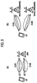
- Inter-eNB CA (or inter-node UP aggregation)" has been considered (refer to Non-patent document 1) in which CA up to LTE Release-10 is expanded such that, as shown in (b) of Fig. 5 , communications are performed simultaneously by using CC#1 and CC#2 under different radio base stations eNB#1 and eNB#2 to achieve high throughput.
- the inter-eNB CA needs to be performed to achieve a degree of throughput comparable to LTE Release-10 when, for example, all CCs cannot be accommodated within one radio base station eNB.
- a radio base station MeNB may serve as an anchor node to forward data addressed to a mobile station UE and transmitted by a gateway apparatus S-GW to the mobile station UE or a radio base station SeNB, as shown in (a) of Fig. 6 .
- the gateway apparatus S-GW may serve as an anchor node to forward data addressed to the mobile station UE to the radio base station MeNB or the radio base station SeNB, as shown in (b) of Fig. 6 .
- Non-patent document 1 3GPP Contribution R2-131782
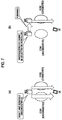
- the radio base station MeNB can dynamically figure out the congestion status of each CC, and thus can select the scheduling-target CC with the congestion status taken into consideration, as shown in (a) of Fig. 7 .
- the radio base station MeNB cannot dynamically figure out the congestion status in the radio base station SeNB, and thus cannot select an uncongested CC as the scheduling-target CC, as shown in (b) of Fig. 7 .
- the backhaul line between the radio base station MeNB and the radio base station SeNB is likely to be formed by a low-speed line such as ADSL instead of a high-speed line such as an optical fiber.
- the radio base station SeNB uses the backhaul line to notify the radio base station MeNB of the congestion status in the radio base station SeNB, there has also been a problem in that the backhaul line causes a delay in the notification.
- the present invention has been made in view of the above problems, and an object thereof is to provide a mobile station that enables scheduling with congestion status of each CC taken into consideration in a case of performing inter-eNB CA using a cell under a radio base station MeNB and a cell under a radio base station SeNB.
- a first feature of the present invention is summarized as a mobile station configured to be capable of performing carrier aggregation using a cell under a master radio base station and a cell under a slave radio base station, including a transmitter configured to transmit a congestion status in the slave radio base station to the master radio base station.
- a mobile communication system according to a first embodiment of the present invention will be described with reference to Figs. 1 to 4 .
- the mobile communication system according to the embodiment will be described by exemplarily presenting an LTE mobile communication system, the present invention is also applicable to other mobile communication systems than LTE mobile communication systems.
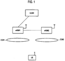
- the mobile communication system includes a gateway apparatus S-GW, a radio base station eNB#1, and a radio base station eNB#2.
- the radio base station eNB#1 is a master radio base station (or macro radio base station configured to manage a macrocell) MeNB.
- the radio base station eNB#2 is a slave radio base station (or a small radio base station configured to manage a small cell) SeNB.
- a mobile station UE is configured to be capable of performing inter-eNB CA using a cell under the radio base station eNB#1 and a cell under the radio base station eNB#2.
- the CC in the cell under the radio base station eNB#1 is CC#1
- the CC in the cell under the radio base station eNB#2 is CC#2.
- the mobile communication system is configured such that data addressed to the mobile station UE and transmitted by the gateway apparatus S-GW is forwarded to the mobile station UE or the radio base station eNB#2 by the radio base station eNB#1, which serves as an anchor node.
- the mobile station UE includes a measurement unit 11, a transmitter 12, and a receiver 13.
- the measurement unit 11 is configured to measure the throughput in a downlink from the radio base station eNB#2, the throughput in an uplink to the radio base station eNB#2, and the like.
- the transmitter 12 is configured to transmit various signals to the radio base station eNB#1 and the radio base station eNB#2.
- the receiver 13 is configured to receive various signals from the radio base station MeNB#1 and the radio base station SeNB#2.
- the transmitter 12 is configured to transmit the congestion status in the radio base station eNB#2 to the radio base station eNB#1.
- the transmitter 12 may be configured to report congestion status to the radio base station eNB#1 that the radio base station eNB#2 is congested in the case where at least one of the throughput of the mobile station UE in the downlink or the throughput of the mobile station UE in the uplink is less than a predetermined threshold.
- the transmitter 12 may be configured to report congestion status to the radio base station eNB#1 that the radio base station eNB#2 is congested in the case where the throughput of the mobile station UE in the downlink is less than a predetermined threshold, and report congestion status to the radio base station eNB#1 that the radio base station eNB#2 is congested in the case where the throughput of the mobile station UE in the uplink is less than a predetermined threshold.
- the transmitter 12 may be configured to report as mentioned above individually for the downlink and the uplink.
- the predetermined threshold compared to the throughput in the downlink and the predetermined threshold compared to the throughput in the uplink may be the same value or different values.
- the transmitter 12 may be configured to report congestion status to the radio base station eNB#1 that the radio base station eNB#2 is congested in the case where the throughput of the mobile station UE in both of the uplink and the downlink in either of the CC#1 and CC#2 is less than a predetermined value.
- the transmitter 12 may be configured to determine for each of the CC#1 and CC#2 whether or not the throughput of the mobile station UE in both of the uplink and the downlink is less than a predetermined threshold, and report congestion status to the radio base station eNB#1 that the radio base station eNB#2 is congested in the case where the throughputs are less than the predetermined thresholds.
- the transmitter 12 may be configured to report the index of the CC with throughput less than the predetermined threshold, in addition to the congestion status.
- the predetermined thresholds compared to the throughputs may be the same value or different values between the CCs.
- the transmitter 12 may be configured to report congestion status to the radio base station eNB#1 that the radio base station eNB#2 is congested in the case where at least one of the throughput of the mobile station UE in the downlink or the throughput of the mobile station UE in the uplink is less than its predetermined threshold for a predetermined length of time.
- the transmitter 12 may be configured to determine whether or not at least one of the two throughputs is less than its predetermined threshold for the predetermined length of time by setting the number of protection stages or a hysteresis.
- the transmitter 12 may be configured to determine the predetermined threshold (s) based on at least one of quality information on the cell under the radio base station eNB#2, setting information on the cell, or QoS of data transmitted in the cell.
- the transmitter 12 may be configured to calculate an expected throughput(s) based on the quality information on the cell under the radio base station eNB#2, the setting information on the cell, or the like, and set the value of the calculated throughput as the predetermined threshold(s).
- CQI Channel Quality Indicator
- RSRP Reference Signal Received Power
- RSRQ Reference Signal Received Quality
- the transmitter 12 may be configured to report as mentioned above for each CC or to report as mentioned above based on the average of the throughputs in the plurality of CCs in the case of performing intra-eNB CA in the radio base station eNB#2 (radio base station SeNB).
- the number of CCs set in the cell mentioned above the number of MIMO (Multi Input Multi Output) layers, or the like may be used.
- the predetermined threshold(s) may be notified by the radio base station eNB#1 (or radio base station eNB#2).
- the transmitter 12 may be configured to report congestion status to the radio base station eNB#1 that the radio base station eNB#2 is congested in the case where the number or total size of packets (RLC-SDU/PDCP-SDU) discarded during a predetermined period of time in a bearer (or logical channel) set in the radio base station eNB#2 is greater than a predetermined threshold.
- RLC-SDU/PDCP-SDU packets
- the transmitter 12 may be configured to report congestion status to the radio base station eNB#1 that the radio base station eNB#2 is congested in the case where the number of times allocation is performed within a predetermined period of time is less than a predetermined threshold during a period in which data is present in a buffer in the bearer (or logical channel) set in the radio base station eNB#2.
- the radio base station eNB#1 includes a receiver 21, a transmitter 22, and a controller 23.
- the receiver 21 is configured to receive various signals from the mobile station UE and the radio base station eNB#2.
- the transmitter 22 is configured to transmit various signals to the mobile station UE and the radio base station eNB#2.
- the controller 23 is configured to perform control related to communication with the mobile station UE (e.g. control related to the inter-eNB CA mentioned above).
- the controller 23 may be configured to stop the inter-eNB CA or change the slave radio base station SeNB from the radio base station eNB#2 to another radio base station eNB based on the received congestion status.
- the transmitter 22 may be configured to transmit the predetermined threshold(s) to the mobile station UE.
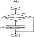
- the radio base station eNB#1 determines whether or not the throughput (s) (Tput) notified by means of the congestion status received from the mobile station UE is less than the predetermined threshold(s) (the value(s) of the throughput(s) expected by the mobile station UE).
- step S102 the radio base station eNB#1 changes the slave radio base station SeNB (radio base station eNB#2).
- the first feature of the embodiment is as follows.
- a mobile station UE is configured to be capable of performing CA (carrier aggregation) using a cell under a radio base station eNB#1 (master radio base station) and a cell under a radio base station eNB#2 (slave radio base station).
- the mobile station UE includes a transmitter 12 configured to transmit a congestion status in the radio base station eNB#2 to the radio base station eNB#1.
- the radio base station eNB#1 can perform scheduling with the congestion status of each CC taken into consideration in the case where the mobile station UE performs inter-eNB CA using the cell under the radio base station MeNB and the cell under the radio base station SeNB.
- the congestion status maybe stored in any signal in the RRC layer.
- the congestion status may be reported as a dummy "measurement report" with which the quality in the cell under the radio base station eNB#2 is assumed to have been lowered significantly.
- the transmitter 12 may report congestion status to the radio base station eNB#1 that the radio base station eNB#2 is congested in the case where at least one of a throughput of the mobile station UE in a downlink or a throughput of the mobile station UE in an uplink is less than a predetermined threshold.
- the radio base station eNB#2 is determined to be congested in the case where at least one of the throughput of the mobile station UE in the downlink or the throughput of the mobile station UE in the uplink is less than the predetermined threshold. In this way, it is possible to quickly detect the occurrence of congestion in the radio base station eNB#2.
- the transmitter 12 may report congestion status to the radio base station eNB#1 that the radio base station eNB#2 is congested in the case where the throughput of the mobile station UE in the downlink is less than the predetermined threshold, and the transmitter 12 may report congestion status to the radio base station eNB#1 that the radio base station eNB#2 is congested in the case where the throughput of the mobile station UE in the uplink is less than the predetermined threshold.
- congestion in the radio base station eNB#2 is reported individually for the downlink and the uplink. In this way, it is possible to perform scheduling with the congestion status taken into consideration independently for the downlink and the uplink.
- the transmitter 12 may report congestion status to the radio base station eNB#1 that the radio base station eNB#2 is congested in the case where the throughput of the mobile station UE in each of the uplink and the downlink in each of CCs is less than the predetermined threshold.
- congestion in the radio base station eNB#2 is reported individually for each CC. In this way, it is possible to perform scheduling with the congestion status taken into consideration independently for each CC.
- the transmitter 12 may report congestion status to the radio base station eNB#1 that the radio base station eNB#2 is congested in the case where at least one of the throughput of the mobile station UE in the downlink or the throughput of the mobile station UE in the uplink is less than the predetermined threshold for a predetermined length of time.
- the mobile station UE can avoid reporting that the radio base station eNB#2 is congested in the case where the throughput(s) decreases only instantaneously.
- the transmitter 12 may determine the predetermined threshold based on at least one of quality information on the cell under the radio base station eNB#2, setting information on the cell, or QoS of data transmitted in the cell.
- the predetermined threshold can be determined with the conditions of the cell under the radio base station eNB#2 taken into consideration.
- the predetermined threshold may be notified of by the radio base station eNB#1. That is, in the first feature of the embodiment, the receiver 13 of the mobile station UE may be configured to receive the predetermined threshold transmitted by the transmitter 22 of the radio base station eNB#1 to be notified to the mobile station UE.
- the predetermined threshold can be determined based on the operator's policy.
- radio base stations eNB#1/eNB#2 and the mobile station UE may be implemented by hardware, may be implemented by a software module executed by a processor, or may be implemented in combination of the hardware and software.
- the software module may be provided on a storage medium in any format, such as RAM (Random Access Memory), flash memory, ROM (Read Only Memory), EPROM (Erasable Programmable ROM), EEPROM (Electronically Erasable and Programmable ROM), a register, a hard disk, a removable disk, or CD-ROM.
- RAM Random Access Memory
- flash memory ROM (Read Only Memory)
- EPROM Erasable Programmable ROM
- EEPROM Electrical Erasable and Programmable ROM
- register a hard disk, a removable disk, or CD-ROM.
- the storage medium is connected to a processor so that the processor can read and write information from and to the storage medium.
- the storage medium may be integrated in a processor.
- the storage medium and the processor may be provided inside an ASIC. Such an ASIC may be provided in the radio base stations eNB#1/eNB#2 and the mobile station UE. Otherwise, the storage medium and the processor may be provided as discrete components inside the radio base stations eNB#1/eNB#2 and the mobile station UE.
- the present invention is applicable to cases where a mobile station is subjected to scheduling with the congestion status of each CC taken into consideration when performing inter-eNB CA.
Landscapes
- Engineering & Computer Science (AREA)
- Computer Networks & Wireless Communication (AREA)
- Signal Processing (AREA)
- Environmental & Geological Engineering (AREA)
- Mobile Radio Communication Systems (AREA)
Abstract
Description
- The present invention relates to a mobile station.
- In CA (Carrier Aggregation) specified up to LTE (Long Term Evolution) Release-10, as shown in (a) of
Fig. 5 , communications are performed simultaneously by using CC (Component Carrier) #1 andCC# 2 under the same radio base station eNB to achieve high throughput. - Meanwhile, in LTE Release-12, "inter-eNB CA (or inter-node UP aggregation)" has been considered (refer to Non-patent document 1) in which CA up to LTE Release-10 is expanded such that, as shown in (b) of
Fig. 5 , communications are performed simultaneously by usingCC# 1 andCC# 2 under different radio base stations eNB#1 and eNB#2 to achieve high throughput. - The inter-eNB CA needs to be performed to achieve a degree of throughput comparable to LTE Release-10 when, for example, all CCs cannot be accommodated within one radio base station eNB.
- The following case is assumed where, in order to perform the inter-eNB CA, a radio base station MeNB may serve as an anchor node to forward data addressed to a mobile station UE and transmitted by a gateway apparatus S-GW to the mobile station UE or a radio base station SeNB, as shown in (a) of
Fig. 6 . - The following case is assumed where, the gateway apparatus S-GW may serve as an anchor node to forward data addressed to the mobile station UE to the radio base station MeNB or the radio base station SeNB, as shown in (b) of
Fig. 6 . - Non-patent document 1: 3GPP Contribution R2-131782
- Here, in the case where intra-eNB CA is performed in the existing LTE system, the radio base station MeNB can dynamically figure out the congestion status of each CC, and thus can select the scheduling-target CC with the congestion status taken into consideration, as shown in (a) of
Fig. 7 . - However, there is a problem in that, in the case where the inter-eNB CA mentioned above is performed in the existing LTE system, the radio base station MeNB cannot dynamically figure out the congestion status in the radio base station SeNB, and thus cannot select an uncongested CC as the scheduling-target CC, as shown in (b) of
Fig. 7 . - The backhaul line between the radio base station MeNB and the radio base station SeNB is likely to be formed by a low-speed line such as ADSL instead of a high-speed line such as an optical fiber.
- For this reason, if the radio base station SeNB uses the backhaul line to notify the radio base station MeNB of the congestion status in the radio base station SeNB, there has also been a problem in that the backhaul line causes a delay in the notification.
- Thus, the present invention has been made in view of the above problems, and an object thereof is to provide a mobile station that enables scheduling with congestion status of each CC taken into consideration in a case of performing inter-eNB CA using a cell under a radio base station MeNB and a cell under a radio base station SeNB.
- A first feature of the present invention is summarized as a mobile station configured to be capable of performing carrier aggregation using a cell under a master radio base station and a cell under a slave radio base station, including a transmitter configured to transmit a congestion status in the slave radio base station to the master radio base station.
-
- [
Fig. 1] Fig. 1 is an overall configuration view of a mobile communication system according to the first embodiment of the present invention. - [
Fig. 2] Fig. 2 is a functional block diagram of a mobile station UE according to the first embodiment of the present invention. - [
Fig. 3] Fig. 3 is a functional block diagram of a radio base station eNB#1 according to the first embodiment of the present invention. - [
Fig. 4] Fig. 4 is a flowchart showing the operation of the radio base stationend## 1 according to the first embodiment of the present invention. - [
Fig. 5 ] (a) ofFig. 5 is a view for describing carrier aggregation specified up to LTE Release-10, and (b) ofFig. 5 is a view for describing inter-eNB CA considered in LTE Release-12. - [
Fig. 6 ] (a) ofFig. 6 is a view for describing a first case expected to occur when inter-eNB CA is performed, and (b) ofFig. 6 is a view for describing a second case expected to occur when inter-eNB CA is performed. - [
Fig. 7 ] (a) ofFig. 7 is a view for describing a case where a scheduling-target CC can be selected with the congestion status of each CC taken into consideration, and (b) ofFig. 7 is a view for describing a case where a scheduling-target CC cannot be selected with the congestion status of each CC taken into consideration. - A mobile communication system according to a first embodiment of the present invention will be described with reference to
Figs. 1 to 4 . Although the mobile communication system according to the embodiment will be described by exemplarily presenting an LTE mobile communication system, the present invention is also applicable to other mobile communication systems than LTE mobile communication systems. - As shown in
Fig. 1 , the mobile communication system according to this embodiment includes a gateway apparatus S-GW, a radio base station eNB#1, and a radio base station eNB#2. - In the mobile communication system according to the embodiment, the radio base station eNB#1 is a master radio base station (or macro radio base station configured to manage a macrocell) MeNB. The radio base station eNB#2 is a slave radio base station (or a small radio base station configured to manage a small cell) SeNB.
- Also, in the mobile communication system according to the embodiment, a mobile station UE is configured to be capable of performing inter-eNB CA using a cell under the radio base station eNB#1 and a cell under the radio base station eNB#2. Here, the CC in the cell under the radio base station eNB#1 is
CC# 1, and the CC in the cell under the radio base station eNB#2 isCC# 2. - Further, as shown in
Fig. 1 , the mobile communication system according to the embodiment is configured such that data addressed to the mobile station UE and transmitted by the gateway apparatus S-GW is forwarded to the mobile station UE or the radio base station eNB#2 by the radio base station eNB#1, which serves as an anchor node. - As shown in
Fig. 2 , the mobile station UE according to the embodiment includes ameasurement unit 11, atransmitter 12, and areceiver 13. - The
measurement unit 11 is configured to measure the throughput in a downlink from the radio base station eNB#2, the throughput in an uplink to the radio base station eNB#2, and the like. - The
transmitter 12 is configured to transmit various signals to the radio base station eNB#1 and the radio base station eNB#2. Thereceiver 13 is configured to receive various signals from the radio base station MeNB#1 and the radio base station SeNB#2. - Also, the
transmitter 12 is configured to transmit the congestion status in the radio base station eNB#2 to the radio base station eNB#1. - Here, the
transmitter 12 may be configured to report congestion status to the radio base station eNB#1 that the radio base station eNB#2 is congested in the case where at least one of the throughput of the mobile station UE in the downlink or the throughput of the mobile station UE in the uplink is less than a predetermined threshold. - Further, the
transmitter 12 may be configured to report congestion status to the radio base station eNB#1 that the radio base station eNB#2 is congested in the case where the throughput of the mobile station UE in the downlink is less than a predetermined threshold, and report congestion status to the radio base station eNB#1 that the radio base station eNB#2 is congested in the case where the throughput of the mobile station UE in the uplink is less than a predetermined threshold. - That is, the
transmitter 12 may be configured to report as mentioned above individually for the downlink and the uplink. - In this case, the predetermined threshold compared to the throughput in the downlink and the predetermined threshold compared to the throughput in the uplink may be the same value or different values.
- Alternatively, the
transmitter 12 may be configured to report congestion status to the radio base station eNB#1 that the radio base station eNB#2 is congested in the case where the throughput of the mobile station UE in both of the uplink and the downlink in either of theCC# 1 andCC# 2 is less than a predetermined value. - That is, the
transmitter 12 may be configured to determine for each of theCC# 1 andCC# 2 whether or not the throughput of the mobile station UE in both of the uplink and the downlink is less than a predetermined threshold, and report congestion status to the radio base station eNB#1 that the radio base station eNB#2 is congested in the case where the throughputs are less than the predetermined thresholds. - In this case, the
transmitter 12 may be configured to report the index of the CC with throughput less than the predetermined threshold, in addition to the congestion status. - Also, the predetermined thresholds compared to the throughputs may be the same value or different values between the CCs.
- Further, the
transmitter 12 may be configured to report congestion status to the radio base station eNB#1 that the radio base station eNB#2 is congested in the case where at least one of the throughput of the mobile station UE in the downlink or the throughput of the mobile station UE in the uplink is less than its predetermined threshold for a predetermined length of time. - In this case, the
transmitter 12 may be configured to determine whether or not at least one of the two throughputs is less than its predetermined threshold for the predetermined length of time by setting the number of protection stages or a hysteresis. - Also, the
transmitter 12 may be configured to determine the predetermined threshold (s) based on at least one of quality information on the cell under the radio base station eNB#2, setting information on the cell, or QoS of data transmitted in the cell. - Specifically, the
transmitter 12 may be configured to calculate an expected throughput(s) based on the quality information on the cell under the radio base station eNB#2, the setting information on the cell, or the like, and set the value of the calculated throughput as the predetermined threshold(s). - Here, as the above quality information, CQI (Channel Quality Indicator), RSRP (Reference Signal Received Power), RSRQ (Reference Signal Received Quality), or the like may be used.
- The
transmitter 12 may be configured to report as mentioned above for each CC or to report as mentioned above based on the average of the throughputs in the plurality of CCs in the case of performing intra-eNB CA in the radio base station eNB#2 (radio base station SeNB). - As the above setting information, the number of CCs set in the cell mentioned above, the number of MIMO (Multi Input Multi Output) layers, or the like may be used.
- Note that the predetermined threshold(s) may be notified by the radio base station eNB#1 (or radio base station eNB#2).
- The
transmitter 12 may be configured to report congestion status to the radio base station eNB#1 that the radio base station eNB#2 is congested in the case where the number or total size of packets (RLC-SDU/PDCP-SDU) discarded during a predetermined period of time in a bearer (or logical channel) set in the radio base station eNB#2 is greater than a predetermined threshold. - The
transmitter 12 may be configured to report congestion status to the radio base station eNB#1 that the radio base station eNB#2 is congested in the case where the number of times allocation is performed within a predetermined period of time is less than a predetermined threshold during a period in which data is present in a buffer in the bearer (or logical channel) set in the radio base station eNB#2. - As shown in
Fig. 3 , the radio base station eNB#1 according to the embodiment includes areceiver 21, atransmitter 22, and acontroller 23. - The
receiver 21 is configured to receive various signals from the mobile station UE and the radio base station eNB#2. Thetransmitter 22 is configured to transmit various signals to the mobile station UE and the radio base station eNB#2. Thecontroller 23 is configured to perform control related to communication with the mobile station UE (e.g. control related to the inter-eNB CA mentioned above). - In the case where the
receiver 21 receives the congestion status from the mobile station UE, thecontroller 23 may be configured to stop the inter-eNB CA or change the slave radio base station SeNB from the radio base station eNB#2 to another radio base station eNB based on the received congestion status. - Also, the
transmitter 22 may be configured to transmit the predetermined threshold(s) to the mobile station UE. - The operation of the radio base station eNB#1 in the mobile communication system according to the embodiment will be described below with reference to
Fig. 4 . - As shown in
Fig. 4 , in step S101, the radio base station eNB#1 determines whether or not the throughput (s) (Tput) notified by means of the congestion status received from the mobile station UE is less than the predetermined threshold(s) (the value(s) of the throughput(s) expected by the mobile station UE). - If "Yes," this operation proceeds to step S102. If "No," this operation ends.
- In step S102, the radio base
station eNB# 1 changes the slave radio base station SeNB (radio base station eNB#2). - The features of the embodiment as described above may also be expressed as follows.
- The first feature of the embodiment is as follows.
- A mobile station UE is configured to be capable of performing CA (carrier aggregation) using a cell under a radio base station eNB#1 (master radio base station) and a cell under a radio base station eNB#2 (slave radio base station). Here, the mobile station UE includes a
transmitter 12 configured to transmit a congestion status in the radio basestation eNB# 2 to the radio basestation eNB# 1. - According to the first feature, the radio base
station eNB# 1 can perform scheduling with the congestion status of each CC taken into consideration in the case where the mobile station UE performs inter-eNB CA using the cell under the radio base station MeNB and the cell under the radio base station SeNB. - Note that the congestion status maybe stored in any signal in the RRC layer. For example, the congestion status may be reported as a dummy "measurement report" with which the quality in the cell under the radio base
station eNB# 2 is assumed to have been lowered significantly. - In the first feature of the embodiment, the
transmitter 12 may report congestion status to the radio basestation eNB# 1 that the radio basestation eNB# 2 is congested in the case where at least one of a throughput of the mobile station UE in a downlink or a throughput of the mobile station UE in an uplink is less than a predetermined threshold. - According to this configuration, the radio base
station eNB# 2 is determined to be congested in the case where at least one of the throughput of the mobile station UE in the downlink or the throughput of the mobile station UE in the uplink is less than the predetermined threshold. In this way, it is possible to quickly detect the occurrence of congestion in the radio basestation eNB# 2. - In the first feature of the embodiment, the
transmitter 12 may report congestion status to the radio basestation eNB# 1 that the radio basestation eNB# 2 is congested in the case where the throughput of the mobile station UE in the downlink is less than the predetermined threshold, and thetransmitter 12 may report congestion status to the radio basestation eNB# 1 that the radio basestation eNB# 2 is congested in the case where the throughput of the mobile station UE in the uplink is less than the predetermined threshold. - According to this configuration, congestion in the radio base
station eNB# 2 is reported individually for the downlink and the uplink. In this way, it is possible to perform scheduling with the congestion status taken into consideration independently for the downlink and the uplink. - In the first feature of the embodiment, the
transmitter 12 may report congestion status to the radio basestation eNB# 1 that the radio basestation eNB# 2 is congested in the case where the throughput of the mobile station UE in each of the uplink and the downlink in each of CCs is less than the predetermined threshold. - According to this configuration, congestion in the radio base
station eNB# 2 is reported individually for each CC. In this way, it is possible to perform scheduling with the congestion status taken into consideration independently for each CC. - In the first feature of the embodiment, the
transmitter 12 may report congestion status to the radio basestation eNB# 1 that the radio basestation eNB# 2 is congested in the case where at least one of the throughput of the mobile station UE in the downlink or the throughput of the mobile station UE in the uplink is less than the predetermined threshold for a predetermined length of time. - According to this configuration, the mobile station UE can avoid reporting that the radio base
station eNB# 2 is congested in the case where the throughput(s) decreases only instantaneously. - In the first feature of the embodiment, the
transmitter 12 may determine the predetermined threshold based on at least one of quality information on the cell under the radio basestation eNB# 2, setting information on the cell, or QoS of data transmitted in the cell. - According to this configuration, the predetermined threshold can be determined with the conditions of the cell under the radio base
station eNB# 2 taken into consideration. - In the first feature of the embodiment, the predetermined threshold may be notified of by the radio base
station eNB# 1. That is, in the first feature of the embodiment, thereceiver 13 of the mobile station UE may be configured to receive the predetermined threshold transmitted by thetransmitter 22 of the radio basestation eNB# 1 to be notified to the mobile station UE. - According to this configuration, the predetermined threshold can be determined based on the operator's policy.
- Note that the foregoing operations of the radio base
stations eNB# 1/eNB# 2 and the mobile station UE may be implemented by hardware, may be implemented by a software module executed by a processor, or may be implemented in combination of the hardware and software. - The software module may be provided on a storage medium in any format, such as RAM (Random Access Memory), flash memory, ROM (Read Only Memory), EPROM (Erasable Programmable ROM), EEPROM (Electronically Erasable and Programmable ROM), a register, a hard disk, a removable disk, or CD-ROM.
- The storage medium is connected to a processor so that the processor can read and write information from and to the storage medium. Alternatively, the storage medium may be integrated in a processor. The storage medium and the processor may be provided inside an ASIC. Such an ASIC may be provided in the radio base
stations eNB# 1/eNB# 2 and the mobile station UE. Otherwise, the storage medium and the processor may be provided as discrete components inside the radio basestations eNB# 1/eNB# 2 and the mobile station UE. - Previously, the present invention has been described in detail by use of the foregoing embodiments. However, it is apparent to those skilled in the art that the present invention should not be limited to the embodiments described in the specification. The present invention can be implemented as an altered or modified embodiment without departing from the spirit and scope of the present invention, which is determined by the description of the scope of claims. Therefore, the description of the specification is intended for illustrative explanation only and does not impose any limited interpretation on the present invention.
- Note that the entire content of Japanese Patent Application No.
2013-214935 (filed on October 15, 2013 - The present invention is applicable to cases where a mobile station is subjected to scheduling with the congestion status of each CC taken into consideration when performing inter-eNB CA.
-
- S-GW
- gateway apparatus
- UE
- mobile station
-
eNB# 1/eNB# 2 - radio base station
- 11
- measurement unit
- 12, 22
- transmitter
- 13, 21
- receiver
- 23
- controller
Claims (8)
- A mobile station configured to be capable of performing carrier aggregation using a first cell under a master radio base station and a second cell under a slave radio base station, comprising a transmitter configured to transmit a congestion status of the slave radio base station to the master radio base station.
- The mobile station according to claim 1, wherein the transmitter is configured to report congestion status to the master radio base station that the slave radio base station is congested in a case where at least one of a throughput of the mobile station in a downlink or a throughput of the mobile station in an uplink is less than a predetermined threshold.
- The mobile station according to claim 2, wherein
the transmitter is configured to report to the master radio base station that the slave radio base station is congested as the congestion status in a case where the throughput in the downlink is less than the predetermined threshold, and
the transmitter is configured to report congestion status to the master radio base station that the slave radio base station is congested in a case where the throughput in the uplink is less than the predetermined threshold. - The mobile station according to claim 2, wherein the transmitter is configured to report congestion status to the master radio base station that the slave radio base station is congested in a case where the throughput in each of component carriers is less than the predetermined threshold.
- The mobile station according to claim 2, wherein the transmitter is configured to report congestion status to the master radio base station that the slave radio base station is congested in a case where at least one of the throughput in the downlink or the throughput in the uplink is less than the predetermined threshold for a predetermined length of time.
- The mobile station according to any one of claims 1 to 5, wherein the transmitter is configured to determine the predetermined threshold based on at least one of quality information on the second cell, setting information on the second cell, or QoS of data transmitted in the second cell.
- The mobile station according to any one of claims 1 to 5, further comprising a receiver configured to receive the predetermined threshold transmitted by the master radio base station.
- The mobile station according to any one of claims 1 to 7, wherein the transmitter is configured to transmit the congestion status in the slave radio base station by using a signal in an RRC layer.
Applications Claiming Priority (2)
| Application Number | Priority Date | Filing Date | Title |
|---|---|---|---|
| JP2013214935A JP6251538B2 (en) | 2013-10-15 | 2013-10-15 | Mobile station |
| PCT/JP2014/075444 WO2015056542A1 (en) | 2013-10-15 | 2014-09-25 | Mobile station |
Publications (2)
| Publication Number | Publication Date |
|---|---|
| EP3059999A1 true EP3059999A1 (en) | 2016-08-24 |
| EP3059999A4 EP3059999A4 (en) | 2016-09-28 |
Family
ID=52827991
Family Applications (1)
| Application Number | Title | Priority Date | Filing Date |
|---|---|---|---|
| EP14853717.8A Withdrawn EP3059999A4 (en) | 2013-10-15 | 2014-09-25 | MOBILE STATION |
Country Status (4)
| Country | Link |
|---|---|
| US (1) | US10306512B2 (en) |
| EP (1) | EP3059999A4 (en) |
| JP (1) | JP6251538B2 (en) |
| WO (1) | WO2015056542A1 (en) |
Families Citing this family (1)
| Publication number | Priority date | Publication date | Assignee | Title |
|---|---|---|---|---|
| CN115551033A (en) * | 2022-09-23 | 2022-12-30 | Oppo广东移动通信有限公司 | Network switching method, device, terminal equipment, storage medium and program product |
Family Cites Families (36)
| Publication number | Priority date | Publication date | Assignee | Title |
|---|---|---|---|---|
| US7391722B2 (en) * | 2004-02-17 | 2008-06-24 | Alcatel Lucent | Method and system for determining link congestion |
| GB2458258A (en) * | 2008-02-04 | 2009-09-16 | Nec Corp | Method of controlling base station loading in a mobile communication system |
| JP5074327B2 (en) * | 2008-08-21 | 2012-11-14 | 株式会社日立製作所 | Routing system |
| WO2010148290A1 (en) * | 2009-06-19 | 2010-12-23 | Interdigital Patent Holdings, Inc. | Method and apparatus for detecting and measuring for home node-bs |
| JP5241645B2 (en) * | 2009-08-04 | 2013-07-17 | 株式会社日立製作所 | Mobile communication system, line connection control method and control station in mobile communication system |
| JP5108865B2 (en) * | 2009-11-30 | 2012-12-26 | 株式会社エヌ・ティ・ティ・ドコモ | Mobile communication terminal, network device, mobile communication system, and mobile communication method |
| US8248981B2 (en) * | 2010-01-21 | 2012-08-21 | Eigent Technologies, Inc. | Method and apparatus for low cost, long range, power efficient, wireless system with enhanced functionality |
| GB201004380D0 (en) * | 2010-03-17 | 2010-04-28 | Vodafone Intellectual Property | Mechanisms for load balancing between eNB/RNC and h(e)NB |
| US8942194B2 (en) * | 2010-05-19 | 2015-01-27 | Qualcomm Incorporated | QOS-based power control in aggregated carrier communication systems |
| TWI407224B (en) * | 2010-07-28 | 2013-09-01 | Au Optronics Corp | Liquid crystal display panel, pixel array substrate and pixel structure thereof |
| US8886198B2 (en) * | 2010-09-28 | 2014-11-11 | Qualcomm Incorporated | Active hang-in for multi-FEMTO deployments |
| KR20120085998A (en) * | 2011-01-25 | 2012-08-02 | 삼성전자주식회사 | Method and apparatus for interference mitigation in heterogeneous network using beamforming |
| ES2404979B1 (en) * | 2011-04-29 | 2014-05-05 | Telefónica, S.A. | METHOD AND SYSTEM FOR SAVING ENERGY AND MINIMIZING THE LEVEL OF INTERFERENCE IN A RADIO ACCESS NODE NETWORK DEPLOYMENT |
| EP3082288B1 (en) * | 2011-11-22 | 2018-01-17 | Huawei Technologies Co., Ltd. | Method and device for implementing lte baseband resource pool |
| CN102726106B (en) * | 2011-11-28 | 2015-08-19 | 华为技术有限公司 | The defining method of power offset parameter and device |
| KR101980093B1 (en) * | 2012-01-27 | 2019-05-20 | 삼성전자주식회사 | Method and system for providing service in a next generation radio communication system |
| US20130237233A1 (en) * | 2012-03-08 | 2013-09-12 | Qualcomm Incorporated | Method and apparatus for offloading devices in femtocell coverage |
| CN102647771B (en) * | 2012-04-10 | 2016-05-25 | 华为技术有限公司 | The discovery of WLAN and system of selection, equipment and system and terminal |
| US10432298B2 (en) * | 2012-04-30 | 2019-10-01 | Hughes Network Systems, Llc | Method and apparatus for dynamic load balancing of communications channels for controlling traffic load in a communications system |
| KR101882669B1 (en) * | 2012-05-11 | 2018-07-30 | 노키아 솔루션스 앤드 네트웍스 오와이 | Method for uplink-downlink interference mitigation in heterogeneous network |
| EP2688348A1 (en) * | 2012-07-16 | 2014-01-22 | Alcatel Lucent | Apparatuses, Methods, and Computer Programs for Base Station Transceivers |
| US8987590B2 (en) * | 2012-08-01 | 2015-03-24 | International Business Machines Corporation | Thin film solar cells |
| WO2014084762A1 (en) * | 2012-11-28 | 2014-06-05 | Telefonaktiebolaget L M Ericsson (Publ) | Method and network node for handling handover |
| US9686677B2 (en) * | 2013-01-17 | 2017-06-20 | Intel IP Corporation | Techniques for deploying small cells as secondary cells for user equipment |
| WO2014111223A1 (en) * | 2013-01-18 | 2014-07-24 | Nokia Solutions And Networks Oy | Transfer from access points outside of a radio access network |
| KR101568310B1 (en) * | 2013-02-01 | 2015-11-12 | 주식회사 케이티 | Methods and apparatuses for transmitting user plane data in small cell deployments |
| US10142879B2 (en) * | 2013-02-20 | 2018-11-27 | Lg Electronics Inc. | Method and apparatus for transmitting cell load information in wireless communication system |
| US9955383B2 (en) * | 2013-02-22 | 2018-04-24 | Lg Electronics Inc. | Method and apparatus for transmitting cell load information in wireless communication system |
| WO2014146272A1 (en) * | 2013-03-21 | 2014-09-25 | Nokia Corporation | Method and apparatus for mobility control in a heterogenous network |
| WO2014182118A1 (en) * | 2013-05-09 | 2014-11-13 | Lg Electronics Inc. | Method and apparatus for transmitting cell load information in wireless communication system |
| US9801099B2 (en) * | 2013-05-15 | 2017-10-24 | Blackberry Limited | Method and system for use of cellular infrastructure to manage small cell access |
| US9497682B2 (en) * | 2013-06-07 | 2016-11-15 | Intel Corporation | Central processing unit and methods for supporting coordinated multipoint transmission in an LTE network |
| WO2015002389A1 (en) * | 2013-07-04 | 2015-01-08 | 엘지전자 주식회사 | Method by which terminal performs communication in heterogeneous cell environment and terminal |
| CN109510697B (en) * | 2013-07-04 | 2021-07-06 | 韩国电子通信研究院 | Methods of handling radio link failures |
| EP3044895B1 (en) * | 2013-09-13 | 2020-04-01 | Nokia Solutions and Networks Oy | Uplink inter-site carrier aggregation based on amount of data to transmit |
| KR102051831B1 (en) * | 2013-09-13 | 2019-12-04 | 삼성전자주식회사 | Method and apparatus for traffic load balancing in mobile communication system |
-
2013
- 2013-10-15 JP JP2013214935A patent/JP6251538B2/en active Active
-
2014
- 2014-09-25 EP EP14853717.8A patent/EP3059999A4/en not_active Withdrawn
- 2014-09-25 WO PCT/JP2014/075444 patent/WO2015056542A1/en not_active Ceased
- 2014-09-25 US US15/029,270 patent/US10306512B2/en active Active
Also Published As
| Publication number | Publication date |
|---|---|
| JP2015080042A (en) | 2015-04-23 |
| WO2015056542A1 (en) | 2015-04-23 |
| EP3059999A4 (en) | 2016-09-28 |
| JP6251538B2 (en) | 2017-12-20 |
| US20160262046A1 (en) | 2016-09-08 |
| US10306512B2 (en) | 2019-05-28 |
Similar Documents
| Publication | Publication Date | Title |
|---|---|---|
| JP7630501B2 (en) | User Equipment Involved in Neighboring Cell Measurement Procedure | |
| KR102693825B1 (en) | Resource selection method, data transmission method and device | |
| US11064413B2 (en) | Communication control device and communication control method with switching off of second cell by switching operation mode | |
| US10390251B2 (en) | Terminal device, base station device, measurement method, and integrated circuit | |
| KR102174133B1 (en) | Method and Apparatus to perform cell measurements and to choose a special cell of small cell in mobile communication system | |
| CN106471755B (en) | System and method for TDD communication | |
| US11330588B2 (en) | Method for selecting carrier and communication device | |
| JP6844853B2 (en) | Terminal and wireless communication method | |
| EP2941044A1 (en) | Load balancing method and network control node | |
| US20190230546A1 (en) | User equipment and transmission method | |
| US10839696B2 (en) | Apparatuses, methods and computer programs for a local platooning controller and a global platooning controller, and a platooning system | |
| EP3437385B1 (en) | Interference control in cellular communication system | |
| CN112751655B (en) | Uplink carrier aggregation method, device, system and storage medium | |
| CN105659679A (en) | Mobile communication system and user equipment device | |
| EP2975899A1 (en) | Terminal apparatus, base station apparatus, communication system, communication method and integrated circuit | |
| CN110731071A (en) | User terminal and wireless communication method | |
| EP4161191A1 (en) | Beam failure recovery method and apparatus, and device | |
| WO2017135344A1 (en) | User terminal, wireless base station, and wireless communication method | |
| WO2021111620A1 (en) | Terminal and measurement report transmission method | |
| CN109803313B (en) | Congestion control method, terminal and computer readable storage medium | |
| US10306512B2 (en) | Mobile station | |
| WO2017135340A1 (en) | User terminal, wireless base station, and wireless communication method | |
| WO2015030119A1 (en) | Radio base station | |
| JP2020155874A (en) | Base station and radio communication control method | |
| JPWO2019182135A1 (en) | Base station and transmission method |
Legal Events
| Date | Code | Title | Description |
|---|---|---|---|
| PUAI | Public reference made under article 153(3) epc to a published international application that has entered the european phase |
Free format text: ORIGINAL CODE: 0009012 |
|
| 17P | Request for examination filed |
Effective date: 20160429 |
|
| AK | Designated contracting states |
Kind code of ref document: A1 Designated state(s): AL AT BE BG CH CY CZ DE DK EE ES FI FR GB GR HR HU IE IS IT LI LT LU LV MC MK MT NL NO PL PT RO RS SE SI SK SM TR |
|
| AX | Request for extension of the european patent |
Extension state: BA ME |
|
| A4 | Supplementary search report drawn up and despatched |
Effective date: 20160831 |
|
| RIC1 | Information provided on ipc code assigned before grant |
Ipc: H04W 28/08 20090101AFI20160825BHEP Ipc: H04W 72/04 20090101ALI20160825BHEP Ipc: H04W 36/22 20090101ALI20160825BHEP |
|
| RAP1 | Party data changed (applicant data changed or rights of an application transferred) |
Owner name: NTT DOCOMO, INC. |
|
| DAX | Request for extension of the european patent (deleted) | ||
| 17Q | First examination report despatched |
Effective date: 20170811 |
|
| GRAP | Despatch of communication of intention to grant a patent |
Free format text: ORIGINAL CODE: EPIDOSNIGR1 |
|
| INTG | Intention to grant announced |
Effective date: 20180504 |
|
| STAA | Information on the status of an ep patent application or granted ep patent |
Free format text: STATUS: THE APPLICATION IS DEEMED TO BE WITHDRAWN |
|
| 18D | Application deemed to be withdrawn |
Effective date: 20180915 |