EP3059749A1 - Circuit breaker including current path geometries that increase contact self-popping level - Google Patents
Circuit breaker including current path geometries that increase contact self-popping level Download PDFInfo
- Publication number
- EP3059749A1 EP3059749A1 EP16155867.1A EP16155867A EP3059749A1 EP 3059749 A1 EP3059749 A1 EP 3059749A1 EP 16155867 A EP16155867 A EP 16155867A EP 3059749 A1 EP3059749 A1 EP 3059749A1
- Authority
- EP
- European Patent Office
- Prior art keywords
- circuit breaker
- stationary contact
- popping
- breaker according
- contact
- Prior art date
- Legal status (The legal status is an assumption and is not a legal conclusion. Google has not performed a legal analysis and makes no representation as to the accuracy of the status listed.)
- Granted
Links
Images



Classifications
-
- H—ELECTRICITY
- H01—ELECTRIC ELEMENTS
- H01H—ELECTRIC SWITCHES; RELAYS; SELECTORS; EMERGENCY PROTECTIVE DEVICES
- H01H73/00—Protective overload circuit-breaking switches in which excess current opens the contacts by automatic release of mechanical energy stored by previous operation of a hand reset mechanism
- H01H73/02—Details
- H01H73/04—Contacts
-
- H—ELECTRICITY
- H01—ELECTRIC ELEMENTS
- H01H—ELECTRIC SWITCHES; RELAYS; SELECTORS; EMERGENCY PROTECTIVE DEVICES
- H01H1/00—Contacts
- H01H1/12—Contacts characterised by the manner in which co-operating contacts engage
- H01H1/14—Contacts characterised by the manner in which co-operating contacts engage by abutting
- H01H1/22—Contacts characterised by the manner in which co-operating contacts engage by abutting with rigid pivoted member carrying the moving contact
-
- H—ELECTRICITY
- H01—ELECTRIC ELEMENTS
- H01H—ELECTRIC SWITCHES; RELAYS; SELECTORS; EMERGENCY PROTECTIVE DEVICES
- H01H1/00—Contacts
- H01H1/02—Contacts characterised by the material thereof
- H01H1/021—Composite material
- H01H1/023—Composite material having a noble metal as the basic material
-
- H—ELECTRICITY
- H01—ELECTRIC ELEMENTS
- H01H—ELECTRIC SWITCHES; RELAYS; SELECTORS; EMERGENCY PROTECTIVE DEVICES
- H01H1/00—Contacts
- H01H1/50—Means for increasing contact pressure, preventing vibration of contacts, holding contacts together after engagement, or biasing contacts to the open position
- H01H1/54—Means for increasing contact pressure, preventing vibration of contacts, holding contacts together after engagement, or biasing contacts to the open position by magnetic force
-
- H—ELECTRICITY
- H01—ELECTRIC ELEMENTS
- H01H—ELECTRIC SWITCHES; RELAYS; SELECTORS; EMERGENCY PROTECTIVE DEVICES
- H01H1/00—Contacts
- H01H1/12—Contacts characterised by the manner in which co-operating contacts engage
- H01H1/14—Contacts characterised by the manner in which co-operating contacts engage by abutting
-
- H—ELECTRICITY
- H01—ELECTRIC ELEMENTS
- H01H—ELECTRIC SWITCHES; RELAYS; SELECTORS; EMERGENCY PROTECTIVE DEVICES
- H01H2203/00—Form of contacts
-
- H—ELECTRICITY
- H01—ELECTRIC ELEMENTS
- H01H—ELECTRIC SWITCHES; RELAYS; SELECTORS; EMERGENCY PROTECTIVE DEVICES
- H01H2203/00—Form of contacts
- H01H2203/036—Form of contacts to solve particular problems
Definitions
- the subject matter disclosed herein relates to the art of circuit breakers and, more particularly, to a circuit breaker including current path geometries that increase contact popping levels.
- a circuit breaker includes one or more stationary contacts and one or more movable contacts that are connected to close a circuit to pass electrical current.
- the movable contact(s) is/are shifted away from the stationary contact(s) to open the circuit.
- the movable contact may chatter or pop at certain current levels. Popping generally results from forces that are generated in a direction of contact opening due to magnetic constriction forces. Popping may create arcing events that reduce an overall service life of the contacts and the circuit breaker.
- a circuit breaker includes a housing, and a movable contact arm arranged in the housing.
- the movable contact arm includes a movable contact.
- a stationary contact assembly is arranged in the housing.
- the stationary contact assembly includes a base member including a first side and an opposing second side.
- An anti-popping recess having a wall portion is formed in one of the first and second sides and defines a cantilevered arm portion.
- a stationary contact member extends from the first side toward the second side.
- a circuit breaker includes a housing, and a first contact assembly arranged in the housing.
- the first contact assembly includes a first contact member.
- a second contact assembly is arranged in the housing.
- the second contact assembly includes a contact portion having a first side and an opposing, second side.
- An anti-popping recess having a wall portion is formed in one of the first and second sides and defines a cantilevered arm portion.
- the first contact assembly being attracted to the second contact assembly upon an application of electrical current through the circuit breaker.
- Circuit breaker 2 includes a housing 4 that encloses a first or movable contact assembly) 6 and a second or stationary contact assembly 8.
- Movable contact assembly 6 includes a movable contact arm 12 that supports a movable contact 14 which, in accordance with an aspect of an exemplary embodiment, may be formed from silver, a silver alloy, or other electrically conductive materials.
- stationary contact assembly 8 includes a contact portion 19 having a base member 20 that is electrically coupled to a lug or connection strap 22.
- Connection strap 22 may provide a connection point for an electrical load (not shown).
- Connection strap 22 may also provide a connection point for a source of electricity or line connection (also not shown).
- Base member 20 includes a first side 24 and an opposing, second side 25.
- Base member 20 may also include a third side (not separately labeled) and an opposing fourth side (also not separately labeled).
- Second side 25 includes an anti-popping recess 28 having a wall portion 30 that is off-set relative to first and second sides 24 and 25. Anti-popping recess 28 establishes a cantilevered arm portion 32 on contact portion 19.
- Wall portion 30, in accordance with the exemplary embodiment shown, extends substantially parallel to first and second sides 24 and 25 and substantially aligns with second end portion 16 of movable contact 14 when circuit breaker 2 is in a closed or electrically conducting configuration such as shown in FIG. 2 .
- contact portion 19 may also include a stationary contact member 34 coupled to base member 20.
- Stationary contact member 34 may be formed from silver, a silver alloy, or other electrically conductive materials and includes an end portion 38 that may be co-extensive or substantially align with second side 25 of base member 20.
- Stationary contact member 34 promotes forward loop attraction forces that reduce repulsion forces and further draw movable contact 14 toward stationary contact member 34.
- a stationary contact member 46 may include an end portion 48 that may be co-extensive or substantially align with wall portion 30.
- anti-popping recess 28 includes a desired depth and a desired height.
- the desired depth is represented by a distance between second side 25 and wall portion 30.
- the desired height e.g., a length of wall portion 30, establishes a desired thickness of cantilevered arm portion 32.
- the desired thickness of cantilevered arm portion 32 in accordance with an exemplary aspect, should be understood to include a thickness of stationary contact member 34. In this manner, anti-popping recess 28 and cantilevered arm portion 32 influence magnetic flux through movable contact 14 and stationary contact member 34.
- a desired ratio of a depth of anti-popping recess 28 verses a thickness of cantilevered arm portion 32 is about 2:7. In accordance with another aspect of an exemplary embodiment, the desired ratio is about 4:6. In accordance with yet another aspect of an exemplary embodiment, the desired ratio is about 3:5.
- the desired ratio may vary depending upon contact geometries, current, and material properties of movable contact assembly 6 and stationary contact assembly 8. Further, it should be understood that the desired height will also affect the desired thickness of cantilevered arm portion 32 and stationary contact member 34 and thus play a role in establishing the desired ratio.
- anti-popping recess 28 establishes desired current flow vectors through stationary contact member 34 and movable contact 14. More specifically, current flow vectors flux lines that pass through stationary contact member 34 are substantially parallel to current flow vectors passing through movable contact 14 thereby generating an attraction force, as shown in FIG. 4 . More specifically, the current flow vectors flow substantially in one direction generating an attraction force. In contrast, prior art flux lines diverge from one another forming a reverse loop, such as shown at 80 in FIG. 5 , creating a repulsion force that may lead to popping at lower current levels. More specifically, in prior art systems, the current flow vectors flow in opposite directions causing popping or chatter at lower current levels.
- base member 20 may include a stationary contact member having a geometry, e.g., a position of an end portion relative to base member, that further promotes magnetic flux field lines that enhance forward loop attraction forces. In this manner, the anti-popping recess and the stationary contact member cooperate to establish an attraction force between the stationary contact portion and movable contact.
- the attraction force opposes repulsion forces that may be created between the stationary contact and the movable contact thereby increasing contact popping level and enhancing performance at higher currents and an overall operational life increase of the circuit breaker.
- the phrase "popping level" should be understood to describe a condition in which a particular current level causes a popping, chatter and/or vibration of the moveable contact relative to the stationary contact.
- Increasing the popping level should be understood to mean that the geometry of the stationary contact member increases the level of current that could lead to popping, chatter and/or vibration of the moveable contact relative to the stationary contact.
- exemplary embodiments increase popping level without a need for additional heavy springs, longer movable contact lever arms, and the like that may be employed to hold contacts together
Landscapes
- Chemical & Material Sciences (AREA)
- Engineering & Computer Science (AREA)
- Composite Materials (AREA)
- Materials Engineering (AREA)
- Contacts (AREA)
Abstract
Description
- The subject matter disclosed herein relates to the art of circuit breakers and, more particularly, to a circuit breaker including current path geometries that increase contact popping levels.
- A circuit breaker includes one or more stationary contacts and one or more movable contacts that are connected to close a circuit to pass electrical current. In the event that the electrical current exceeds predetermined parameters, such as during a short circuit event, the movable contact(s) is/are shifted away from the stationary contact(s) to open the circuit. In some cases, the movable contact may chatter or pop at certain current levels. Popping generally results from forces that are generated in a direction of contact opening due to magnetic constriction forces. Popping may create arcing events that reduce an overall service life of the contacts and the circuit breaker.
- According to one aspect of an exemplary embodiment, a circuit breaker includes a housing, and a movable contact arm arranged in the housing. The movable contact arm includes a movable contact. A stationary contact assembly is arranged in the housing. The stationary contact assembly includes a base member including a first side and an opposing second side. An anti-popping recess having a wall portion is formed in one of the first and second sides and defines a cantilevered arm portion. A stationary contact member extends from the first side toward the second side.
- According to another aspect of an exemplary embodiment, a circuit breaker includes a housing, and a first contact assembly arranged in the housing. The first contact assembly includes a first contact member. A second contact assembly is arranged in the housing. The second contact assembly includes a contact portion having a first side and an opposing, second side. An anti-popping recess having a wall portion is formed in one of the first and second sides and defines a cantilevered arm portion.
- The first contact assembly being attracted to the second contact assembly upon an application of electrical current through the circuit breaker.
- These and other advantages and features will become more apparent from the following description taken in conjunction with the drawings.
- The subject matter, which is regarded as the invention, is particularly pointed out and distinctly claimed in the claims at the conclusion of the specification. The foregoing and other features, and advantages of the invention are apparent from the following detailed description taken in conjunction with the accompanying drawings in which:
-
FIG. 1 depicts a circuit breaker including contacts having a current path geometry that increases a contact popping level shown in an open configuration, in accordance with an exemplary embodiment; -
FIG. 2 depicts the circuit breaker ofFIG. 1 with the contacts having a current path geometry that increases a contact popping level shown in a closed configuration; -
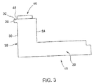
FIG. 3 depicts a circuit breaker contact having a current path geometry that increases a contact popping level, in accordance with aspect of an exemplary embodiment; -
FIG. 4 depicts current flow vectors passing through the circuit breaker contact ofFIG. 2 ; and -
FIG. 5 depicts current flow vectors passing through a prior art circuit breaker contact. - The detailed description explains embodiments of the invention, together with advantages and features, by way of example with reference to the drawings.
- A circuit breaker, in accordance with an exemplary embodiment, is indicated generally at 2, in
FIG. 1 .Circuit breaker 2 includes ahousing 4 that encloses a first or movable contact assembly) 6 and a second or stationary contact assembly 8.Movable contact assembly 6 includes amovable contact arm 12 that supports amovable contact 14 which, in accordance with an aspect of an exemplary embodiment, may be formed from silver, a silver alloy, or other electrically conductive materials. - In accordance with an exemplary embodiment, stationary contact assembly 8 includes a
contact portion 19 having abase member 20 that is electrically coupled to a lug orconnection strap 22.Connection strap 22 may provide a connection point for an electrical load (not shown).Connection strap 22 may also provide a connection point for a source of electricity or line connection (also not shown).Base member 20 includes afirst side 24 and an opposing,second side 25.Base member 20 may also include a third side (not separately labeled) and an opposing fourth side (also not separately labeled).Second side 25 includes ananti-popping recess 28 having awall portion 30 that is off-set relative to first andsecond sides Anti-popping recess 28 establishes a cantileveredarm portion 32 oncontact portion 19.Wall portion 30, in accordance with the exemplary embodiment shown, extends substantially parallel to first andsecond sides second end portion 16 ofmovable contact 14 whencircuit breaker 2 is in a closed or electrically conducting configuration such as shown inFIG. 2 . - Anti-popping recess 28 promotes magnetic flux lines that establish an attractive force which draws
movable contact 14 towardcontact portion 19. In addition,contact portion 19 may also include astationary contact member 34 coupled tobase member 20.Stationary contact member 34 may be formed from silver, a silver alloy, or other electrically conductive materials and includes anend portion 38 that may be co-extensive or substantially align withsecond side 25 ofbase member 20.Stationary contact member 34 promotes forward loop attraction forces that reduce repulsion forces and further drawmovable contact 14 towardstationary contact member 34. In accordance with another aspect of an exemplary embodiment illustrated inFIG. 3 , astationary contact member 46 may include anend portion 48 that may be co-extensive or substantially align withwall portion 30. - In accordance with an aspect of an exemplary embodiment,
anti-popping recess 28 includes a desired depth and a desired height. The desired depth is represented by a distance betweensecond side 25 andwall portion 30. The desired height, e.g., a length ofwall portion 30, establishes a desired thickness of cantileveredarm portion 32. The desired thickness of cantileveredarm portion 32, in accordance with an exemplary aspect, should be understood to include a thickness ofstationary contact member 34. In this manner, anti-popping recess 28 and cantileveredarm portion 32 influence magnetic flux throughmovable contact 14 andstationary contact member 34. In accordance with an aspect of an exemplary embodiment, a desired ratio of a depth of anti-popping recess 28 verses a thickness of cantileveredarm portion 32 is about 2:7. In accordance with another aspect of an exemplary embodiment, the desired ratio is about 4:6. In accordance with yet another aspect of an exemplary embodiment, the desired ratio is about 3:5. Of course, it should be understood that the desired ratio may vary depending upon contact geometries, current, and material properties ofmovable contact assembly 6 and stationary contact assembly 8. Further, it should be understood that the desired height will also affect the desired thickness of cantileveredarm portion 32 andstationary contact member 34 and thus play a role in establishing the desired ratio. - In further accordance with an exemplary embodiment,
anti-popping recess 28 establishes desired current flow vectors throughstationary contact member 34 andmovable contact 14. More specifically, current flow vectors flux lines that pass throughstationary contact member 34 are substantially parallel to current flow vectors passing throughmovable contact 14 thereby generating an attraction force, as shown inFIG. 4 . More specifically, the current flow vectors flow substantially in one direction generating an attraction force. In contrast, prior art flux lines diverge from one another forming a reverse loop, such as shown at 80 inFIG. 5 , creating a repulsion force that may lead to popping at lower current levels. More specifically, in prior art systems, the current flow vectors flow in opposite directions causing popping or chatter at lower current levels. - At this point, it should be understood that the anti-popping recess shapes magnetic flux field lines and current density fields flowing through
contact portion 19 causing a reduction in reverse loop forces that may reduce the repulsion ofmovable contact 14 away frombase member 20. In addition,base member 20 may include a stationary contact member having a geometry, e.g., a position of an end portion relative to base member, that further promotes magnetic flux field lines that enhance forward loop attraction forces. In this manner, the anti-popping recess and the stationary contact member cooperate to establish an attraction force between the stationary contact portion and movable contact. The attraction force opposes repulsion forces that may be created between the stationary contact and the movable contact thereby increasing contact popping level and enhancing performance at higher currents and an overall operational life increase of the circuit breaker. The phrase "popping level" should be understood to describe a condition in which a particular current level causes a popping, chatter and/or vibration of the moveable contact relative to the stationary contact. Increasing the popping level should be understood to mean that the geometry of the stationary contact member increases the level of current that could lead to popping, chatter and/or vibration of the moveable contact relative to the stationary contact. Further, exemplary embodiments increase popping level without a need for additional heavy springs, longer movable contact lever arms, and the like that may be employed to hold contacts together - While the invention has been described in detail in connection with only a limited number of embodiments, it should be readily understood that the invention is not limited to such disclosed embodiments. Rather, the invention can be modified to incorporate any number of variations, alterations, substitutions or equivalent arrangements not heretofore described, but which are commensurate with the spirit and scope of the invention. Additionally, while various embodiments of the invention have been described, it is to be understood that aspects of the invention may include only some of the described embodiments. Accordingly, the invention is not to be seen as limited by the foregoing description, but is only limited by the scope of the appended claims.
- Various aspects and embodiments of the present invention are defined with the following numbered clauses:
- 1. A circuit breaker comprising:
- a housing;
- a movable contact arm arranged in the housing, the movable contact arm including a movable contact; and
- a stationary contact assembly arranged in the housing, the stationary contact assembly including a base member including a first side and an opposing second side, an anti-popping recess formed in one of the first and second sides defining a cantilevered arm portion, and a stationary contact member extending from the first side toward the second side.
- 2. The circuit breaker according to claim 1, wherein the stationary contact member extends along the cantilevered arm portion and includes an end portion that is substantially co-extensive with the second side of the base member.
- 3. The circuit breaker according to
clause 2, wherein the stationary contact member comprises at least one of silver and alloys of silver. - 4. The circuit breaker according to clause 1 or
clause 2, wherein the stationary contact member includes an end portion that is substantially co-extensive with the wall portion. - 5. The circuit breaker according to any preceding clause, wherein the stationary contact member comprises at least one of silver and alloys of silver.
- 6. The circuit breaker according to any preceding clause, wherein the movable contact includes a first end portion, a second end portion and an intermediate portion extending between the first end portion and the second end portion, the first end portion being substantially co-extensive with the wall portion when the movable contact engages the stationary contact assembly.
- 7. The circuit breaker according to any preceding clause, wherein the movable contact comprises at least one of silver and alloys of silver.
- 8. The circuit breaker according to any preceding clause, wherein the stationary contact member comprises one of silver and alloys of silver.
- 9. The circuit breaker according to any preceding clause, wherein the anti-popping recess includes a depth and the cantilevered arm portion and stationary contact member include a thickness, the depth being at a desired ratio relative to the thickness of about 2:7.
- 10. The circuit breaker according to any preceding clause, wherein the desired ratio is about 4:6.
- 11. The circuit breaker according to any preceding clause, wherein the desired ratio is about 3:5.
- 12. The circuit breaker according to any preceding clause, wherein the anti-popping recess includes a wall portion having a depth dimension that is greater than a width of the stationary contact member and the cantilevered arm portion.
- 13. A circuit breaker comprising:
- a housing;
- a first contact assembly arranged in the housing, the first contact assembly including a first contact member; and
- a second contact assembly arranged in the housing, the second contact assembly including a contact portion having a first side and an opposing, second side, and an anti-popping recess formed in one of the first and second sides defining a cantilevered arm portion, the first contact assembly being attracted toward the second contact assembly upon an application of electrical current through the circuit breaker.
- 14. The circuit breaker according to any preceding clause, further comprising a stationary contact member extending across the second contact assembly from the first side toward the second side, the stationary contact member including an end portion that is substantially co-extensive with the second side of the base member.
- 15. The circuit breaker according to any preceding clause, wherein the stationary contact member comprises silver.
- 16. The circuit breaker according to any preceding clause, further comprising a stationary contact member extending across the second contact assembly from the first side toward the second side, the stationary contact member including an end portion that is substantially co-extensive with the wall portion.
- 17. The circuit breaker according to any preceding clause, wherein the stationary contact member comprises at least one of silver and alloys of silver.
- 18. The circuit breaker according to any preceding clause, wherein the first contact member comprises one of silver and alloys of silver.
- 19. The circuit breaker according to any preceding clause, wherein the anti-popping recess includes a depth and the cantilevered arm portion includes a thickness, the height being at a desired ratio relative to the thickness of about 2:7.
- 20. The circuit breaker according to any preceding clause, wherein the anti-popping recess includes a wall portion having a depth dimension that is greater than a width of the stationary contact member and the cantilevered arm portion.
Claims (15)
- A circuit breaker (2) comprising:a housing (4);a movable contact arm (12) arranged in the housing (4), the movable contact arm (12) including a movable contact (14); anda stationary contact assembly (8) arranged in the housing (4), the stationary contact assembly (8) including a base member (20) including a first side (24) and an opposing second side (25), an anti-popping recess (28) formed in one of the first and second sides defining a cantilevered arm portion (32), and a stationary contact member (34) extending from the first side (24) toward the second side (25).
- The circuit breaker according to claim 1, wherein the stationary contact member (34) extends along the cantilevered arm portion (32) and includes an end portion that is substantially co-extensive with the second side of the base member.
- The circuit breaker according to claim 1 or claim 2, wherein the stationary contact member (34) comprises at least one of silver and alloys of silver.
- The circuit breaker according to any preceding claim, wherein the stationary contact member (34) includes an end portion that is substantially co-extensive with the wall portion.
- The circuit breaker according to any preceding claim, wherein the stationary contact member (34) comprises at least one of silver and alloys of silver.
- The circuit breaker according to any preceding claim, wherein the movable contact (14) includes a first end portion, a second end portion and an intermediate portion extending between the first end portion and the second end portion, the first end portion being substantially co-extensive with the wall portion when the movable contact engages the stationary contact assembly.
- The circuit breaker according to any preceding claim, wherein the movable contact (14) comprises at least one of silver and alloys of silver.
- The circuit breaker according to any preceding claim, wherein the stationary contact (34) member comprises one of silver and alloys of silver.
- The circuit breaker according to any preceding claim, wherein the anti-popping recess (28) includes a depth and the cantilevered arm portion and stationary contact member include a thickness, the depth being at a desired ratio relative to the thickness of about 2:7.
- The circuit breaker according to claim 9, wherein the desired ratio is about 4:6.
- The circuit breaker according to claim 10, wherein the desired ratio is about 3:5.
- The circuit breaker according to any preceding claim, wherein the anti-popping recess includes a wall portion having a depth dimension that is greater than a width of the stationary contact member and the cantilevered arm portion.
- A circuit breaker comprising:a housing;a first contact assembly arranged in the housing, the first contact assembly including a first contact member; anda second contact assembly arranged in the housing, the second contact assembly including a contact portion having a first side and an opposing, second side, and an anti-popping recess formed in one of the first and second sides defining a cantilevered arm portion, the first contact assembly being attracted toward the second contact assembly upon an application of electrical current through the circuit breaker.
- The circuit breaker according to claim 13, further comprising a stationary contact member extending across the second contact assembly from the first side toward the second side, the stationary contact member including an end portion that is substantially co-extensive with the second side of the base member.
- The circuit breaker according to claim 13 or claim 14, wherein the stationary contact member comprises silver.
Applications Claiming Priority (1)
| Application Number | Priority Date | Filing Date | Title |
|---|---|---|---|
| US14/624,471 US20160240329A1 (en) | 2015-02-17 | 2015-02-17 | Circuit breaker including current path geometries that increase contact popping level |
Publications (2)
| Publication Number | Publication Date |
|---|---|
| EP3059749A1 true EP3059749A1 (en) | 2016-08-24 |
| EP3059749B1 EP3059749B1 (en) | 2022-11-30 |
Family
ID=55361395
Family Applications (1)
| Application Number | Title | Priority Date | Filing Date |
|---|---|---|---|
| EP16155867.1A Active EP3059749B1 (en) | 2015-02-17 | 2016-02-16 | Circuit breaker including current path geometries that increase contact self-popping level |
Country Status (3)
| Country | Link |
|---|---|
| US (1) | US20160240329A1 (en) |
| EP (1) | EP3059749B1 (en) |
| CN (2) | CN105895465A (en) |
Citations (8)
| Publication number | Priority date | Publication date | Assignee | Title |
|---|---|---|---|---|
| US2025697A (en) * | 1933-04-22 | 1935-12-24 | Westinghouse Electric & Mfg Co | Circuit interrupter |
| FR1086026A (en) * | 1953-07-01 | 1955-02-09 | Alsthom Cgee | Arrangement causing the pressure of electrical contacts to increase when the current intensity reaches a high value |
| US2777921A (en) * | 1953-06-16 | 1957-01-15 | Merlin Gerin | Face-on-face contact pair for circuit breakers |
| DE966034C (en) * | 1942-01-25 | 1957-07-04 | Voigt & Haeffner Ag | Spring-loaded block contact |
| JPS5459154U (en) * | 1977-09-30 | 1979-04-24 | ||
| JP2004311293A (en) * | 2003-04-09 | 2004-11-04 | Toyota Motor Corp | Relay device |
| US20040239459A1 (en) * | 2001-09-06 | 2004-12-02 | Michael Bach | Switch contact arrangement comprising a device for increasing a contact-force acting between switch contacts |
| US20070209827A1 (en) * | 2003-09-30 | 2007-09-13 | Michael Kruschke | Connecting Bar Arrangement for an Electric Switch and Electric Switch Comprising a Connecting Bar Arrangement |
Family Cites Families (7)
| Publication number | Priority date | Publication date | Assignee | Title |
|---|---|---|---|---|
| US5815058A (en) * | 1997-04-02 | 1998-09-29 | Onan Corporation | Contact enhancement apparatus for an electric switch |
| US6015957A (en) * | 1998-12-31 | 2000-01-18 | General Electric Company | High ampacity pinless conducting joint in movable contact arm assembly |
| US20020053066A1 (en) * | 2000-03-17 | 2002-05-02 | Richter Timothy Gerard | Circuit breaker mechanism modeling |
| US6437266B1 (en) * | 2000-09-22 | 2002-08-20 | General Electric Company | Electrical contact arm assembly for a circuit breaker |
| US7646269B2 (en) * | 2007-03-07 | 2010-01-12 | Eaton Corporation | Electrical switching apparatus, and conductor assembly and shunt assembly therefor |
| CN201130648Y (en) * | 2007-12-17 | 2008-10-08 | 宁波市华安电力电气股份有限公司 | Long direction breaker |
| WO2011097612A1 (en) * | 2010-02-08 | 2011-08-11 | Siemens Aktiengesellschaft | Circuit breaker electrical contact assembly, and systems and methods using same |
-
2015
- 2015-02-17 US US14/624,471 patent/US20160240329A1/en not_active Abandoned
-
2016
- 2016-02-16 EP EP16155867.1A patent/EP3059749B1/en active Active
- 2016-02-17 CN CN201610088450.XA patent/CN105895465A/en active Pending
- 2016-02-17 CN CN202210137512.7A patent/CN114446735A/en active Pending
Patent Citations (8)
| Publication number | Priority date | Publication date | Assignee | Title |
|---|---|---|---|---|
| US2025697A (en) * | 1933-04-22 | 1935-12-24 | Westinghouse Electric & Mfg Co | Circuit interrupter |
| DE966034C (en) * | 1942-01-25 | 1957-07-04 | Voigt & Haeffner Ag | Spring-loaded block contact |
| US2777921A (en) * | 1953-06-16 | 1957-01-15 | Merlin Gerin | Face-on-face contact pair for circuit breakers |
| FR1086026A (en) * | 1953-07-01 | 1955-02-09 | Alsthom Cgee | Arrangement causing the pressure of electrical contacts to increase when the current intensity reaches a high value |
| JPS5459154U (en) * | 1977-09-30 | 1979-04-24 | ||
| US20040239459A1 (en) * | 2001-09-06 | 2004-12-02 | Michael Bach | Switch contact arrangement comprising a device for increasing a contact-force acting between switch contacts |
| JP2004311293A (en) * | 2003-04-09 | 2004-11-04 | Toyota Motor Corp | Relay device |
| US20070209827A1 (en) * | 2003-09-30 | 2007-09-13 | Michael Kruschke | Connecting Bar Arrangement for an Electric Switch and Electric Switch Comprising a Connecting Bar Arrangement |
Also Published As
| Publication number | Publication date |
|---|---|
| EP3059749B1 (en) | 2022-11-30 |
| US20160240329A1 (en) | 2016-08-18 |
| CN105895465A (en) | 2016-08-24 |
| CN114446735A (en) | 2022-05-06 |
Similar Documents
| Publication | Publication Date | Title |
|---|---|---|
| CN107230570B (en) | Electrical switching apparatus and arc chute assembly and related circuit protection method | |
| US10056200B2 (en) | Electromagnetic contactor | |
| US8981883B2 (en) | Contact mechanism and electromagnetic contactor using same | |
| EP3940734B1 (en) | Electromagnetic relay | |
| US9378914B2 (en) | Contact device and electromagnetic contactor using the same | |
| CN107533927B (en) | Contactor Assembly | |
| US12080496B2 (en) | Contactor with integrated drive shaft and yoke | |
| CN101145453A (en) | Contact device for electrical equipment and electrical equipment equipped with the same | |
| JP5056571B2 (en) | Circuit breaker | |
| EP3059749B1 (en) | Circuit breaker including current path geometries that increase contact self-popping level | |
| EP3827458A1 (en) | Solenoid assembly with decreased release time | |
| CN102959672A (en) | Contact mechanism and electromagnetic contactor using same | |
| JP7563108B2 (en) | Electromagnetic Relay | |
| CN113692629A (en) | Electrical assembly having contacts with improved mating surfaces | |
| US11942296B2 (en) | Contactor | |
| KR102842352B1 (en) | electronic relay | |
| JP5387728B2 (en) | Circuit breaker | |
| KR20260069656A (en) | Relay | |
| US11728114B2 (en) | Low-voltage switching device including an electromagnetic contact load support | |
| JP4401810B2 (en) | Circuit breaker | |
| WO2021001471A1 (en) | Switching contact system for a switching system | |
| JP2020115432A (en) | relay | |
| JP2016177914A (en) | Switchgear |
Legal Events
| Date | Code | Title | Description |
|---|---|---|---|
| PUAI | Public reference made under article 153(3) epc to a published international application that has entered the european phase |
Free format text: ORIGINAL CODE: 0009012 |
|
| AK | Designated contracting states |
Kind code of ref document: A1 Designated state(s): AL AT BE BG CH CY CZ DE DK EE ES FI FR GB GR HR HU IE IS IT LI LT LU LV MC MK MT NL NO PL PT RO RS SE SI SK SM TR |
|
| AX | Request for extension of the european patent |
Extension state: BA ME |
|
| STAA | Information on the status of an ep patent application or granted ep patent |
Free format text: STATUS: REQUEST FOR EXAMINATION WAS MADE |
|
| 17P | Request for examination filed |
Effective date: 20170224 |
|
| RBV | Designated contracting states (corrected) |
Designated state(s): AL AT BE BG CH CY CZ DE DK EE ES FI FR GB GR HR HU IE IS IT LI LT LU LV MC MK MT NL NO PL PT RO RS SE SI SK SM TR |
|
| STAA | Information on the status of an ep patent application or granted ep patent |
Free format text: STATUS: EXAMINATION IS IN PROGRESS |
|
| 17Q | First examination report despatched |
Effective date: 20180329 |
|
| RAP1 | Party data changed (applicant data changed or rights of an application transferred) |
Owner name: ABB SCHWEIZ AG |
|
| RAP3 | Party data changed (applicant data changed or rights of an application transferred) |
Owner name: ABB SCHWEIZ AG |
|
| RAP1 | Party data changed (applicant data changed or rights of an application transferred) |
Owner name: ABB S.P.A. |
|
| GRAP | Despatch of communication of intention to grant a patent |
Free format text: ORIGINAL CODE: EPIDOSNIGR1 |
|
| STAA | Information on the status of an ep patent application or granted ep patent |
Free format text: STATUS: GRANT OF PATENT IS INTENDED |
|
| INTG | Intention to grant announced |
Effective date: 20220711 |
|
| GRAS | Grant fee paid |
Free format text: ORIGINAL CODE: EPIDOSNIGR3 |
|
| GRAA | (expected) grant |
Free format text: ORIGINAL CODE: 0009210 |
|
| STAA | Information on the status of an ep patent application or granted ep patent |
Free format text: STATUS: THE PATENT HAS BEEN GRANTED |
|
| AK | Designated contracting states |
Kind code of ref document: B1 Designated state(s): AL AT BE BG CH CY CZ DE DK EE ES FI FR GB GR HR HU IE IS IT LI LT LU LV MC MK MT NL NO PL PT RO RS SE SI SK SM TR |
|
| REG | Reference to a national code |
Ref country code: CH Ref legal event code: EP Ref country code: GB Ref legal event code: FG4D |
|
| REG | Reference to a national code |
Ref country code: AT Ref legal event code: REF Ref document number: 1535320 Country of ref document: AT Kind code of ref document: T Effective date: 20221215 |
|
| REG | Reference to a national code |
Ref country code: IE Ref legal event code: FG4D |
|
| REG | Reference to a national code |
Ref country code: DE Ref legal event code: R096 Ref document number: 602016076562 Country of ref document: DE |
|
| REG | Reference to a national code |
Ref country code: LT Ref legal event code: MG9D |
|
| REG | Reference to a national code |
Ref country code: NL Ref legal event code: MP Effective date: 20221130 |
|
| PG25 | Lapsed in a contracting state [announced via postgrant information from national office to epo] |
Ref country code: SE Free format text: LAPSE BECAUSE OF FAILURE TO SUBMIT A TRANSLATION OF THE DESCRIPTION OR TO PAY THE FEE WITHIN THE PRESCRIBED TIME-LIMIT Effective date: 20221130 Ref country code: PT Free format text: LAPSE BECAUSE OF FAILURE TO SUBMIT A TRANSLATION OF THE DESCRIPTION OR TO PAY THE FEE WITHIN THE PRESCRIBED TIME-LIMIT Effective date: 20230331 Ref country code: NO Free format text: LAPSE BECAUSE OF FAILURE TO SUBMIT A TRANSLATION OF THE DESCRIPTION OR TO PAY THE FEE WITHIN THE PRESCRIBED TIME-LIMIT Effective date: 20230228 Ref country code: LT Free format text: LAPSE BECAUSE OF FAILURE TO SUBMIT A TRANSLATION OF THE DESCRIPTION OR TO PAY THE FEE WITHIN THE PRESCRIBED TIME-LIMIT Effective date: 20221130 Ref country code: FI Free format text: LAPSE BECAUSE OF FAILURE TO SUBMIT A TRANSLATION OF THE DESCRIPTION OR TO PAY THE FEE WITHIN THE PRESCRIBED TIME-LIMIT Effective date: 20221130 Ref country code: ES Free format text: LAPSE BECAUSE OF FAILURE TO SUBMIT A TRANSLATION OF THE DESCRIPTION OR TO PAY THE FEE WITHIN THE PRESCRIBED TIME-LIMIT Effective date: 20221130 |
|
| REG | Reference to a national code |
Ref country code: AT Ref legal event code: MK05 Ref document number: 1535320 Country of ref document: AT Kind code of ref document: T Effective date: 20221130 |
|
| PG25 | Lapsed in a contracting state [announced via postgrant information from national office to epo] |
Ref country code: RS Free format text: LAPSE BECAUSE OF FAILURE TO SUBMIT A TRANSLATION OF THE DESCRIPTION OR TO PAY THE FEE WITHIN THE PRESCRIBED TIME-LIMIT Effective date: 20221130 Ref country code: PL Free format text: LAPSE BECAUSE OF FAILURE TO SUBMIT A TRANSLATION OF THE DESCRIPTION OR TO PAY THE FEE WITHIN THE PRESCRIBED TIME-LIMIT Effective date: 20221130 Ref country code: LV Free format text: LAPSE BECAUSE OF FAILURE TO SUBMIT A TRANSLATION OF THE DESCRIPTION OR TO PAY THE FEE WITHIN THE PRESCRIBED TIME-LIMIT Effective date: 20221130 Ref country code: IS Free format text: LAPSE BECAUSE OF FAILURE TO SUBMIT A TRANSLATION OF THE DESCRIPTION OR TO PAY THE FEE WITHIN THE PRESCRIBED TIME-LIMIT Effective date: 20230330 Ref country code: HR Free format text: LAPSE BECAUSE OF FAILURE TO SUBMIT A TRANSLATION OF THE DESCRIPTION OR TO PAY THE FEE WITHIN THE PRESCRIBED TIME-LIMIT Effective date: 20221130 Ref country code: GR Free format text: LAPSE BECAUSE OF FAILURE TO SUBMIT A TRANSLATION OF THE DESCRIPTION OR TO PAY THE FEE WITHIN THE PRESCRIBED TIME-LIMIT Effective date: 20230301 |
|
| PG25 | Lapsed in a contracting state [announced via postgrant information from national office to epo] |
Ref country code: NL Free format text: LAPSE BECAUSE OF FAILURE TO SUBMIT A TRANSLATION OF THE DESCRIPTION OR TO PAY THE FEE WITHIN THE PRESCRIBED TIME-LIMIT Effective date: 20221130 |
|
| PG25 | Lapsed in a contracting state [announced via postgrant information from national office to epo] |
Ref country code: SM Free format text: LAPSE BECAUSE OF FAILURE TO SUBMIT A TRANSLATION OF THE DESCRIPTION OR TO PAY THE FEE WITHIN THE PRESCRIBED TIME-LIMIT Effective date: 20221130 Ref country code: RO Free format text: LAPSE BECAUSE OF FAILURE TO SUBMIT A TRANSLATION OF THE DESCRIPTION OR TO PAY THE FEE WITHIN THE PRESCRIBED TIME-LIMIT Effective date: 20221130 Ref country code: EE Free format text: LAPSE BECAUSE OF FAILURE TO SUBMIT A TRANSLATION OF THE DESCRIPTION OR TO PAY THE FEE WITHIN THE PRESCRIBED TIME-LIMIT Effective date: 20221130 Ref country code: DK Free format text: LAPSE BECAUSE OF FAILURE TO SUBMIT A TRANSLATION OF THE DESCRIPTION OR TO PAY THE FEE WITHIN THE PRESCRIBED TIME-LIMIT Effective date: 20221130 Ref country code: CZ Free format text: LAPSE BECAUSE OF FAILURE TO SUBMIT A TRANSLATION OF THE DESCRIPTION OR TO PAY THE FEE WITHIN THE PRESCRIBED TIME-LIMIT Effective date: 20221130 Ref country code: AT Free format text: LAPSE BECAUSE OF FAILURE TO SUBMIT A TRANSLATION OF THE DESCRIPTION OR TO PAY THE FEE WITHIN THE PRESCRIBED TIME-LIMIT Effective date: 20221130 |
|
| PG25 | Lapsed in a contracting state [announced via postgrant information from national office to epo] |
Ref country code: SK Free format text: LAPSE BECAUSE OF FAILURE TO SUBMIT A TRANSLATION OF THE DESCRIPTION OR TO PAY THE FEE WITHIN THE PRESCRIBED TIME-LIMIT Effective date: 20221130 Ref country code: AL Free format text: LAPSE BECAUSE OF FAILURE TO SUBMIT A TRANSLATION OF THE DESCRIPTION OR TO PAY THE FEE WITHIN THE PRESCRIBED TIME-LIMIT Effective date: 20221130 |
|
| REG | Reference to a national code |
Ref country code: DE Ref legal event code: R097 Ref document number: 602016076562 Country of ref document: DE |
|
| REG | Reference to a national code |
Ref country code: DE Ref legal event code: R119 Ref document number: 602016076562 Country of ref document: DE |
|
| PG25 | Lapsed in a contracting state [announced via postgrant information from national office to epo] |
Ref country code: MC Free format text: LAPSE BECAUSE OF FAILURE TO SUBMIT A TRANSLATION OF THE DESCRIPTION OR TO PAY THE FEE WITHIN THE PRESCRIBED TIME-LIMIT Effective date: 20221130 |
|
| REG | Reference to a national code |
Ref country code: CH Ref legal event code: PL |
|
| PLBE | No opposition filed within time limit |
Free format text: ORIGINAL CODE: 0009261 |
|
| STAA | Information on the status of an ep patent application or granted ep patent |
Free format text: STATUS: NO OPPOSITION FILED WITHIN TIME LIMIT |
|
| REG | Reference to a national code |
Ref country code: BE Ref legal event code: MM Effective date: 20230228 |
|
| GBPC | Gb: european patent ceased through non-payment of renewal fee |
Effective date: 20230228 |
|
| PG25 | Lapsed in a contracting state [announced via postgrant information from national office to epo] |
Ref country code: LU Free format text: LAPSE BECAUSE OF NON-PAYMENT OF DUE FEES Effective date: 20230216 Ref country code: LI Free format text: LAPSE BECAUSE OF NON-PAYMENT OF DUE FEES Effective date: 20230228 Ref country code: CH Free format text: LAPSE BECAUSE OF NON-PAYMENT OF DUE FEES Effective date: 20230228 |
|
| 26N | No opposition filed |
Effective date: 20230831 |
|
| PG25 | Lapsed in a contracting state [announced via postgrant information from national office to epo] |
Ref country code: SI Free format text: LAPSE BECAUSE OF FAILURE TO SUBMIT A TRANSLATION OF THE DESCRIPTION OR TO PAY THE FEE WITHIN THE PRESCRIBED TIME-LIMIT Effective date: 20221130 |
|
| REG | Reference to a national code |
Ref country code: IE Ref legal event code: MM4A |
|
| PG25 | Lapsed in a contracting state [announced via postgrant information from national office to epo] |
Ref country code: GB Free format text: LAPSE BECAUSE OF NON-PAYMENT OF DUE FEES Effective date: 20230228 |
|
| PG25 | Lapsed in a contracting state [announced via postgrant information from national office to epo] |
Ref country code: IE Free format text: LAPSE BECAUSE OF NON-PAYMENT OF DUE FEES Effective date: 20230216 Ref country code: GB Free format text: LAPSE BECAUSE OF NON-PAYMENT OF DUE FEES Effective date: 20230228 Ref country code: FR Free format text: LAPSE BECAUSE OF NON-PAYMENT OF DUE FEES Effective date: 20230228 Ref country code: DE Free format text: LAPSE BECAUSE OF NON-PAYMENT OF DUE FEES Effective date: 20230901 |
|
| PG25 | Lapsed in a contracting state [announced via postgrant information from national office to epo] |
Ref country code: BE Free format text: LAPSE BECAUSE OF NON-PAYMENT OF DUE FEES Effective date: 20230228 |
|
| PG25 | Lapsed in a contracting state [announced via postgrant information from national office to epo] |
Ref country code: BG Free format text: LAPSE BECAUSE OF FAILURE TO SUBMIT A TRANSLATION OF THE DESCRIPTION OR TO PAY THE FEE WITHIN THE PRESCRIBED TIME-LIMIT Effective date: 20221130 |
|
| PG25 | Lapsed in a contracting state [announced via postgrant information from national office to epo] |
Ref country code: BG Free format text: LAPSE BECAUSE OF FAILURE TO SUBMIT A TRANSLATION OF THE DESCRIPTION OR TO PAY THE FEE WITHIN THE PRESCRIBED TIME-LIMIT Effective date: 20221130 |
|
| PG25 | Lapsed in a contracting state [announced via postgrant information from national office to epo] |
Ref country code: CY Free format text: LAPSE BECAUSE OF FAILURE TO SUBMIT A TRANSLATION OF THE DESCRIPTION OR TO PAY THE FEE WITHIN THE PRESCRIBED TIME-LIMIT; INVALID AB INITIO Effective date: 20160216 |
|
| PG25 | Lapsed in a contracting state [announced via postgrant information from national office to epo] |
Ref country code: HU Free format text: LAPSE BECAUSE OF FAILURE TO SUBMIT A TRANSLATION OF THE DESCRIPTION OR TO PAY THE FEE WITHIN THE PRESCRIBED TIME-LIMIT; INVALID AB INITIO Effective date: 20160216 |
|
| PG25 | Lapsed in a contracting state [announced via postgrant information from national office to epo] |
Ref country code: TR Free format text: LAPSE BECAUSE OF FAILURE TO SUBMIT A TRANSLATION OF THE DESCRIPTION OR TO PAY THE FEE WITHIN THE PRESCRIBED TIME-LIMIT Effective date: 20221130 |
|
| PGFP | Annual fee paid to national office [announced via postgrant information from national office to epo] |
Ref country code: IT Payment date: 20260224 Year of fee payment: 11 |