EP3059715B1 - Wireless sensor device with voice annunciation of signal strength - Google Patents
Wireless sensor device with voice annunciation of signal strength Download PDFInfo
- Publication number
- EP3059715B1 EP3059715B1 EP16155125.4A EP16155125A EP3059715B1 EP 3059715 B1 EP3059715 B1 EP 3059715B1 EP 16155125 A EP16155125 A EP 16155125A EP 3059715 B1 EP3059715 B1 EP 3059715B1
- Authority
- EP
- European Patent Office
- Prior art keywords
- voice
- radio
- wireless device
- signal strength
- sensor
- Prior art date
- Legal status (The legal status is an assumption and is not a legal conclusion. Google has not performed a legal analysis and makes no representation as to the accuracy of the status listed.)
- Active
Links
Images

Classifications
-
- H—ELECTRICITY
- H04—ELECTRIC COMMUNICATION TECHNIQUE
- H04B—TRANSMISSION
- H04B17/00—Monitoring; Testing
- H04B17/20—Monitoring; Testing of receivers
- H04B17/23—Indication means, e.g. displays, alarms, audible means
-
- H—ELECTRICITY
- H04—ELECTRIC COMMUNICATION TECHNIQUE
- H04W—WIRELESS COMMUNICATION NETWORKS
- H04W24/00—Supervisory, monitoring or testing arrangements
- H04W24/04—Arrangements for maintaining operational condition
-
- G—PHYSICS
- G08—SIGNALLING
- G08B—SIGNALLING SYSTEMS, e.g. PERSONAL CALLING SYSTEMS; ORDER TELEGRAPHS; ALARM SYSTEMS
- G08B29/00—Checking or monitoring of signalling or alarm systems; Prevention or correction of operating errors, e.g. preventing unauthorised operation
- G08B29/02—Monitoring continuously signalling or alarm systems
- G08B29/04—Monitoring of the detection circuits
-
- G—PHYSICS
- G08—SIGNALLING
- G08B—SIGNALLING SYSTEMS, e.g. PERSONAL CALLING SYSTEMS; ORDER TELEGRAPHS; ALARM SYSTEMS
- G08B29/00—Checking or monitoring of signalling or alarm systems; Prevention or correction of operating errors, e.g. preventing unauthorised operation
- G08B29/02—Monitoring continuously signalling or alarm systems
- G08B29/06—Monitoring of the line circuits, e.g. signalling of line faults
-
- H—ELECTRICITY
- H04—ELECTRIC COMMUNICATION TECHNIQUE
- H04B—TRANSMISSION
- H04B17/00—Monitoring; Testing
- H04B17/30—Monitoring; Testing of propagation channels
- H04B17/309—Measuring or estimating channel quality parameters
- H04B17/318—Received signal strength
-
- H—ELECTRICITY
- H04—ELECTRIC COMMUNICATION TECHNIQUE
- H04L—TRANSMISSION OF DIGITAL INFORMATION, e.g. TELEGRAPHIC COMMUNICATION
- H04L41/00—Arrangements for maintenance, administration or management of data switching networks, e.g. of packet switching networks
- H04L41/50—Network service management, e.g. ensuring proper service fulfilment according to agreements
- H04L41/5003—Managing SLA; Interaction between SLA and QoS
Definitions
- the present invention relates generally to wireless devices. More particularly, the present invention relates to a system and method of voice annunciation of signal strength, quality of service, and sensor status for wireless devices.
- wireless devices include a radio with a limited range.
- a limited radio range can cause difficulty during the installation of the device, especially when the device is installed in an area with marginal reception conditions.
- a wireless device is installed in a region with marginal reception conditions, a user may have to revisit the device to remedy an installation issue, thereby incurring additional cost.
- Range finding techniques are known, but often rely on a blinking LED, beep, or other cryptic annunciation.
- Some wireless devices can be networked together in various configurations, such as a hub and spoke or mesh configuration, using a variety network protocols.
- Network protocols have failure modes, such as packet collision, packet corruption, and the like.
- known wireless devices are limited to simple voice annunciation of such conditions. Indeed, when additional information is available, known systems and methods have only allowed users to access such information via a software application on a smart phone, a website, and the like. Such tools can be cumbersome to use during an installation process.
- EP patent application, publication number 2264681A1 discloses a signal strength testing method for a wireless device.
- the present invention provides for a wireless device as claimed in the accompanying claims.
- Examples disclosed herein include systems and methods of voice annunciation of signal strength, quality of service, and sensor status for wireless devices.
- some embodiments can provide a user with information for allowing the user to quickly, intuitively, and decisively determine the quality of service that a wireless device with an integral radio is able to receive and provide, determine and diagnose quality of service issues with a wireless device, and determine the status of a sensor in a wireless device and the necessary actions to take in the event of a sensor maintenance event, all without relying on smart phone software applications, blinking LEDs, beeps, or other cryptic annunciations.
- some systems and methods disclosed herein can provide voice annunciation of instructions and guidance to a user during a sensor maintenance event and other detected events and conditions.
- a wireless device can include a voice annunciation module that can execute one or more software applications that include, for example, a quality of service algorithm for detecting and tracking signal strength of the wireless device's radio or for detecting and tracking quality of service events and statistics, such as dropped packets, interferences, network collisions, and the like.
- a quality of service algorithm for detecting and tracking signal strength of the wireless device's radio or for detecting and tracking quality of service events and statistics, such as dropped packets, interferences, network collisions, and the like.
- the wireless device can be placed in an installation mode by actuating a push button or test switch, providing a voice command, or the like.
- the device can provide a range finding function that can operate intermittently or continuously to determine the range of the device's radio and verbally annunciate information relating to the determined range, thereby allowing hands free operation for an user.
- the wireless device claimed can provide real time guidance and instructions to a user regarding the range of a wireless device's radio, such as, when the device is almost out of range, verbally annunciating the phrase: "Low signal. Move device closer to central monitoring station.”
- the device when in the installation mode, can verbally annunciate information and instructions relating to detected quality of service events and statistics.
- quality of service events and statistics can be cleared, either individually or as a group, via a further command received from a user, for example, by actuating a button or switch, providing a voice command, or the like.
- a wireless device can include a voice annunciation module that can execute one or more software applications that include, for example, a sensor monitoring algorithm for detecting failure modes of device sensors. While the device is being serviced, a user can provide input to the device, for example, by actuating a button or switch, providing a voice command, or the like, to solicit voice annunciation from the device that includes details about the device sensors. Details about device sensors that can be annunciated by system and methods disclosed herein include, but are not limited to, remaining battery life, cleanliness of a sensor, remaining sensor life, and recommendations on actions to take when a sensor threshold level is reached.
- a service company can maintain a group of sensors and can download specific threshold levels to a wireless device.
- a threshold level can be specific to a type of maintenance event.
- service requirements can be determined and set according to the location of the wireless device or the application of the wireless device. For example, a wireless device in a harsh environment can have a lower threshold level for maintenance than a wireless device is a mild environment.
- FIG. 1 is a block diagram of a wireless device 100 in accordance with disclosed embodiments.
- the wireless device 100 can include at least an actuator 110, a microphone 120, a radio 130, one or more sensors 140, a battery 150, and a voice annunciation module 160.
- the actuator 110 and the microphone 120 can receive input from a user for placing the device 100 in an installation mode, service mode, maintenance mode, and the like.
- the actuator 110 can include a push button or test switch that can be depressed or toggled by the user.
- the microphone 120 can receive a voice command from the user, which can be sent to the voice annunciation module 160 or other control circuitry in the device 100 for processing.
- user input can include instructions for handling detected quality of service events and statistics.
- the voice annunciation module 160 can include a voice annunciator 162, control circuitry 164, one or more programmable processors 166, and executable control software 168 as would be understood by one of ordinary skill in the art.
- the executable control software 168 can be stored on a transitory or non-transitory computer readable medium, including, but not limited to, local computer memory, RAM, optical storage media, magnetic storage media, flash memory, and the like.
- the executable control software 168 can include software applications or programmed algorithms that can be executed.
- the executable control software 168 can execute a software application that includes a quality of service algorithm for detecting and tracking signal strength of the radio 130, for determining the range of the radio 130, or for detecting and tracking quality of service events and statistics for the device 100 as described herein.
- the executable control software 168 can execute a software application that includes a sensor monitoring algorithm for detecting a failure mode of the sensor 140, the remaining life of the battery 150, or details about the state of the sensor 140.
- the control circuitry 164, the programmable processor 166, or the executable control software 168 can transmit data or instructions to the voice annunciator 162 for annunciation thereof.
- a signal sent to the voice annunciator 162 can include guidance regarding the determined range of the radio 130, information related to detected quality of service events and statistics for the device 100, information related to the sensor 140 or the battery 150, or instructions on actions to take when predetermined sensor events are detected, such as when a sensor threshold level is detected.
- the control circuitry 164 can access predetermined phrases that are saved in a local or remote database or storage medium to retrieve a phrase for verbal annunciation thereof according to a condition determined or detected by the device 100.
- the wireless device 100 can communicate with a central monitoring station 200 or with other wireless devices 100 in a region R.
- the central monitoring station 200 can transmit a signal that can be detected by the radio 130 in the wireless device 100.
- the control circuitry 164, programmable processor 166, and executable control software 168 can use the signal received from the central monitoring station 200 when executing a quality of service algorithm for detecting and tracking signal strength of the radio 130 and for determining the range of the radio 130.
- the central monitoring station 200 can transmit one or more signals to the wireless device 100 for downloading specific information thereto, such as a threshold level for the sensor 140, according to the region R in which the device 100 is located.
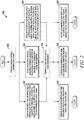
- FIG. 2 is a flow diagram of a method 300 in accordance with disclosed examples. As seen in FIG. 2 , the method 300 can include, a wireless device entering an installation mode, for example, responsive to received user input as in 305.
- the method 300 can also include a voice annunciation module of the wireless device executing a software application that includes a quality of service algorithm for detecting and tracking signal strength of the wireless device's radio and for determining the range of the radio as in 310, a voice annunciation module of the wireless device executing a software application that includes a quality of service algorithm for detecting and tracking quality of service events and statistics as in 315, and/or a voice annunciation module of the wireless device executing a software application that includes a sensor monitoring algorithm for detecting failure modes of sensors, for detecting battery life, and for detecting details about the state of the wireless device's sensors as in 320.
- some or all of the execution as in 310, 315, and 320 can be performed continuously, intermittently, simultaneously, sequentially, individually, automatically, or responsive to a received signal, command, or user input.
- the method 300 can also include, optionally, the wireless device receiving user input to solicit voice annunciation as in 325.
- the method 300 can include the wireless device verbally annunciating information and instructions related to the determined range of the device's radio as in 330, the wireless device verbally annunciating information and instructions related to detected quality of service events and statistics as in 335, and/or the wireless device verbally annunciating information and instructions related to the device's sensors and the maintenance thereof as in 340.
- some or all of the verbal annunciation as in 330, 335, and 340 can be performed continuously, intermittently, simultaneously, sequentially, individually, automatically, or responsive to a received signal, command, or user input.
- the method 300 shown in FIG. 2 and others in accordance with disclosed embodiments can be controlled and/or executed by the control circuitry 164 that is part of the voice annunciation module 160 and/or by any other control circuitry in the wireless device 100.
Landscapes
- Engineering & Computer Science (AREA)
- Physics & Mathematics (AREA)
- Signal Processing (AREA)
- Computer Networks & Wireless Communication (AREA)
- Electromagnetism (AREA)
- Computer Security & Cryptography (AREA)
- General Physics & Mathematics (AREA)
- Quality & Reliability (AREA)
- Mobile Radio Communication Systems (AREA)
- Telephone Function (AREA)
- Arrangements For Transmission Of Measured Signals (AREA)
- Alarm Systems (AREA)
- Telephonic Communication Services (AREA)
Description
- The present invention relates generally to wireless devices. More particularly, the present invention relates to a system and method of voice annunciation of signal strength, quality of service, and sensor status for wireless devices.
- Many wireless devices, including, for example, smoke detectors, carbon dioxide detectors, security devices, and other types of sensors, are known in the art. However, such devices have various limitations.
- For example, many wireless devices include a radio with a limited range. A limited radio range can cause difficulty during the installation of the device, especially when the device is installed in an area with marginal reception conditions. For example, when a wireless device is installed in a region with marginal reception conditions, a user may have to revisit the device to remedy an installation issue, thereby incurring additional cost. Range finding techniques are known, but often rely on a blinking LED, beep, or other cryptic annunciation.
- Some wireless devices can be networked together in various configurations, such as a hub and spoke or mesh configuration, using a variety network protocols. Network protocols have failure modes, such as packet collision, packet corruption, and the like. However, known wireless devices are limited to simple voice annunciation of such conditions. Indeed, when additional information is available, known systems and methods have only allowed users to access such information via a software application on a smart phone, a website, and the like. Such tools can be cumbersome to use during an installation process.
- When a wireless device is installed in a region, sensors therein must often be maintained. However, when a user is inexperienced with wireless devices, sensors, and sensor failure modes, any visit by the user can take longer than necessary. Voice annunciation of maintenance events in wireless devices is known. However, information provided by known systems and methods has not been sufficient for assisting a user attending to the device.
- In view of the above limitations and others, there is a continuing, ongoing need for improved systems and methods of installing and maintaining wireless devices.
-
EP patent application, publication number 2264681A1 discloses a signal strength testing method for a wireless device. - The present invention provides for a wireless device as claimed in the accompanying claims.
-
-
FIG. 1 is a block diagram of a wireless device in accordance with disclosed embodiments; and -
FIG. 2 is a flow diagram of a method in accordance with disclosed embodiments. - While this invention is susceptible of an embodiment in many different forms, there are shown in the drawings and will be described herein in detail specific embodiments thereof with the understanding that the present disclosure is to be considered as an exemplification of the principles of the invention. It is not intended to limit the invention to the specific illustrated embodiments.
- Examples disclosed herein include systems and methods of voice annunciation of signal strength, quality of service, and sensor status for wireless devices. For example, some embodiments can provide a user with information for allowing the user to quickly, intuitively, and decisively determine the quality of service that a wireless device with an integral radio is able to receive and provide, determine and diagnose quality of service issues with a wireless device, and determine the status of a sensor in a wireless device and the necessary actions to take in the event of a sensor maintenance event, all without relying on smart phone software applications, blinking LEDs, beeps, or other cryptic annunciations. Indeed, some systems and methods disclosed herein can provide voice annunciation of instructions and guidance to a user during a sensor maintenance event and other detected events and conditions.
- According to the present invention, a wireless device can include a voice annunciation module that can execute one or more software applications that include, for example, a quality of service algorithm for detecting and tracking signal strength of the wireless device's radio or for detecting and tracking quality of service events and statistics, such as dropped packets, interferences, network collisions, and the like.
- The wireless device can be placed in an installation mode by actuating a push button or test switch, providing a voice command, or the like. When in the installation mode, the device can provide a range finding function that can operate intermittently or continuously to determine the range of the device's radio and verbally annunciate information relating to the determined range, thereby allowing hands free operation for an user. The wireless device claimed can provide real time guidance and instructions to a user regarding the range of a wireless device's radio, such as, when the device is almost out of range, verbally annunciating the phrase: "Low signal. Move device closer to central monitoring station."
- Additionally or alternatively, when in the installation mode, the device can verbally annunciate information and instructions relating to detected quality of service events and statistics. In some embodiments, quality of service events and statistics can be cleared, either individually or as a group, via a further command received from a user, for example, by actuating a button or switch, providing a voice command, or the like.
- In some embodiments, a wireless device can include a voice annunciation module that can execute one or more software applications that include, for example, a sensor monitoring algorithm for detecting failure modes of device sensors. While the device is being serviced, a user can provide input to the device, for example, by actuating a button or switch, providing a voice command, or the like, to solicit voice annunciation from the device that includes details about the device sensors. Details about device sensors that can be annunciated by system and methods disclosed herein include, but are not limited to, remaining battery life, cleanliness of a sensor, remaining sensor life, and recommendations on actions to take when a sensor threshold level is reached.
- In some embodiments, a service company can maintain a group of sensors and can download specific threshold levels to a wireless device. For example, a threshold level can be specific to a type of maintenance event. Additionally or alternatively, service requirements can be determined and set according to the location of the wireless device or the application of the wireless device. For example, a wireless device in a harsh environment can have a lower threshold level for maintenance than a wireless device is a mild environment.
-
FIG. 1 is a block diagram of awireless device 100 in accordance with disclosed embodiments. As seen inFIG. 1 , thewireless device 100 can include at least anactuator 110, amicrophone 120, aradio 130, one ormore sensors 140, abattery 150, and avoice annunciation module 160. - The
actuator 110 and themicrophone 120 can receive input from a user for placing thedevice 100 in an installation mode, service mode, maintenance mode, and the like. For example, theactuator 110 can include a push button or test switch that can be depressed or toggled by the user. Additionally or alternatively, themicrophone 120 can receive a voice command from the user, which can be sent to thevoice annunciation module 160 or other control circuitry in thedevice 100 for processing. In some embodiments, user input can include instructions for handling detected quality of service events and statistics. - The
voice annunciation module 160 can include avoice annunciator 162,control circuitry 164, one or moreprogrammable processors 166, andexecutable control software 168 as would be understood by one of ordinary skill in the art. Theexecutable control software 168 can be stored on a transitory or non-transitory computer readable medium, including, but not limited to, local computer memory, RAM, optical storage media, magnetic storage media, flash memory, and the like. - In some embodiments, the
executable control software 168 can include software applications or programmed algorithms that can be executed. For example, in some embodiments, theexecutable control software 168 can execute a software application that includes a quality of service algorithm for detecting and tracking signal strength of theradio 130, for determining the range of theradio 130, or for detecting and tracking quality of service events and statistics for thedevice 100 as described herein. Additionally or alternatively, in some embodiments, theexecutable control software 168 can execute a software application that includes a sensor monitoring algorithm for detecting a failure mode of thesensor 140, the remaining life of thebattery 150, or details about the state of thesensor 140. - During or after execution of the software applications or programmed algorithms, the
control circuitry 164, theprogrammable processor 166, or theexecutable control software 168 can transmit data or instructions to thevoice annunciator 162 for annunciation thereof. For example, in some embodiments a signal sent to thevoice annunciator 162 can include guidance regarding the determined range of theradio 130, information related to detected quality of service events and statistics for thedevice 100, information related to thesensor 140 or thebattery 150, or instructions on actions to take when predetermined sensor events are detected, such as when a sensor threshold level is detected. In some embodiments, thecontrol circuitry 164 can access predetermined phrases that are saved in a local or remote database or storage medium to retrieve a phrase for verbal annunciation thereof according to a condition determined or detected by thedevice 100. - In accordance with the present invention, the
wireless device 100 can communicate with acentral monitoring station 200 or with otherwireless devices 100 in a region R. For example, thecentral monitoring station 200 can transmit a signal that can be detected by theradio 130 in thewireless device 100. Thecontrol circuitry 164,programmable processor 166, andexecutable control software 168 can use the signal received from thecentral monitoring station 200 when executing a quality of service algorithm for detecting and tracking signal strength of theradio 130 and for determining the range of theradio 130. In some embodiments, thecentral monitoring station 200 can transmit one or more signals to thewireless device 100 for downloading specific information thereto, such as a threshold level for thesensor 140, according to the region R in which thedevice 100 is located. -
FIG. 2 is a flow diagram of amethod 300 in accordance with disclosed examples. As seen inFIG. 2 , themethod 300 can include, a wireless device entering an installation mode, for example, responsive to received user input as in 305. - The
method 300 can also include a voice annunciation module of the wireless device executing a software application that includes a quality of service algorithm for detecting and tracking signal strength of the wireless device's radio and for determining the range of the radio as in 310, a voice annunciation module of the wireless device executing a software application that includes a quality of service algorithm for detecting and tracking quality of service events and statistics as in 315, and/or a voice annunciation module of the wireless device executing a software application that includes a sensor monitoring algorithm for detecting failure modes of sensors, for detecting battery life, and for detecting details about the state of the wireless device's sensors as in 320. In some embodiments, some or all of the execution as in 310, 315, and 320 can be performed continuously, intermittently, simultaneously, sequentially, individually, automatically, or responsive to a received signal, command, or user input. - As seen in
FIG. 2 , themethod 300 can also include, optionally, the wireless device receiving user input to solicit voice annunciation as in 325. After receiving the user input as in 325 or upon the occurrence or detection of a predetermined event, themethod 300 can include the wireless device verbally annunciating information and instructions related to the determined range of the device's radio as in 330, the wireless device verbally annunciating information and instructions related to detected quality of service events and statistics as in 335, and/or the wireless device verbally annunciating information and instructions related to the device's sensors and the maintenance thereof as in 340. In some embodiments, some or all of the verbal annunciation as in 330, 335, and 340 can be performed continuously, intermittently, simultaneously, sequentially, individually, automatically, or responsive to a received signal, command, or user input. - It is to be understood that the
method 300 shown inFIG. 2 and others in accordance with disclosed embodiments can be controlled and/or executed by thecontrol circuitry 164 that is part of thevoice annunciation module 160 and/or by any other control circuitry in thewireless device 100. - Although a few embodiments have been described in detail above, other modifications are possible. For example, the logic flows described above do not require the particular order described, or sequential order, to achieve desirable results. Other steps may be provided, or steps may be eliminated, from the described flows, and other components may be added to, or removed from, the described systems. Other embodiments may be within the scope of the invention.
Claims (3)
- A wireless sensor device (100) with:a sensor (140);an integrated radio (130); anda voice annunciation module (160) in communication with the radio, whereby, in an installation mode, the voice annunciation module (160):intermittently or continuously determines a signal strength of a signal received by the radio from a central monitoring station (200); anddetermines and verbally annunciates real time guidance and instructions related to the determined range of the radio based on the signal strength including to move closer to the central monitoring station.
- The device of claim 1 further comprising a user input device for receiving user input.
- The device of claim 1 wherein the voice annunciation module includes a voice annunciator (162) and control circuitry (164).
Applications Claiming Priority (1)
| Application Number | Priority Date | Filing Date | Title |
|---|---|---|---|
| US14/627,288 US9900115B2 (en) | 2015-02-20 | 2015-02-20 | System and method of voice annunciation of signal strength, quality of service, and sensor status for wireless devices |
Publications (3)
| Publication Number | Publication Date |
|---|---|
| EP3059715A2 EP3059715A2 (en) | 2016-08-24 |
| EP3059715A3 EP3059715A3 (en) | 2016-09-07 |
| EP3059715B1 true EP3059715B1 (en) | 2021-01-06 |
Family
ID=55521389
Family Applications (1)
| Application Number | Title | Priority Date | Filing Date |
|---|---|---|---|
| EP16155125.4A Active EP3059715B1 (en) | 2015-02-20 | 2016-02-10 | Wireless sensor device with voice annunciation of signal strength |
Country Status (4)
| Country | Link |
|---|---|
| US (1) | US9900115B2 (en) |
| EP (1) | EP3059715B1 (en) |
| CN (1) | CN105916169B (en) |
| CA (1) | CA2920476C (en) |
Families Citing this family (6)
| Publication number | Priority date | Publication date | Assignee | Title |
|---|---|---|---|---|
| BR102015032311B1 (en) * | 2015-12-22 | 2023-10-17 | Robert Bosch Limitada | PROCESS OF DEPLOYING A MESH NETWORK AND NODE DEVICE OF A MESH NETWORK |
| US10755555B2 (en) * | 2017-09-18 | 2020-08-25 | Johnson Controls Fire Protection LP | Method and apparatus for verifying service of installed devices using RFID |
| US10735418B2 (en) | 2017-09-18 | 2020-08-04 | Johnson Controls Fire Protection LP | Method and system for service verification using access control system |
| US10681667B2 (en) | 2017-09-18 | 2020-06-09 | Johnson Controls Fire Protection LP | Method and system for service verification using WiFi signal strength mapping |
| US11687048B2 (en) | 2017-09-18 | 2023-06-27 | Johnson Controls Tyco IP Holdings LLP | Method and apparatus for evaluation of temperature sensors |
| US10850868B1 (en) * | 2018-05-29 | 2020-12-01 | Rockwell Collins, Inc. | Operational scenario specific adaptive sensor voter |
Family Cites Families (30)
| Publication number | Priority date | Publication date | Assignee | Title |
|---|---|---|---|---|
| US3641496A (en) * | 1969-06-23 | 1972-02-08 | Phonplex Corp | Electronic voice annunciating system having binary data converted into audio representations |
| US4603325A (en) | 1984-06-05 | 1986-07-29 | Pittway Corporation | Evaluation apparatus |
| US4683459A (en) * | 1985-05-28 | 1987-07-28 | Adt, Inc. | Alarm system test annunciator |
| US5113380A (en) * | 1989-08-24 | 1992-05-12 | Levine Alfred B | Multiple option electronic scheduler and rescheduler |
| JP2575218B2 (en) * | 1989-12-05 | 1997-01-22 | 良太郎 初井 | High-speed labor-saving medical examination device |
| US6441723B1 (en) * | 1999-11-15 | 2002-08-27 | General Electric Company | Highly reliable power line communications system |
| US6753786B1 (en) | 2000-08-11 | 2004-06-22 | Walter Kidde Portable Equipment, Inc. | Microprocessor-based combination smoke and carbon monoxide detector having intelligent hush feature |
| GB0104282D0 (en) * | 2001-02-21 | 2001-04-11 | Cambridge Silicon Radio Ltd | Communication system |
| US20030048203A1 (en) * | 2001-07-19 | 2003-03-13 | Clary David E. | Flight management annunciator panel and system |
| US7040455B2 (en) * | 2001-09-10 | 2006-05-09 | Ncr Corporation | System and method for tracking items at a scale of a self-checkout terminal |
| US7006618B1 (en) * | 2001-11-09 | 2006-02-28 | Cisco Technology, Inc. | Method and apparatus for managing incoming and outgoing calls at an endpoint placed on hold |
| US7596373B2 (en) * | 2002-03-21 | 2009-09-29 | Mcgregor Christopher M | Method and system for quality of service (QoS) monitoring for wireless devices |
| US20040219906A1 (en) * | 2003-05-02 | 2004-11-04 | Benco David S. | Wireless verbal announcing method and system |
| GB0409617D0 (en) * | 2004-04-30 | 2004-06-02 | Ibm | A method and system for determining the location of an improved carrier signal |
| US8598864B2 (en) * | 2004-12-23 | 2013-12-03 | Power Survey Llc | Apparatus and method for monitoring and controlling detection of stray voltage anomalies |
| US7495553B2 (en) | 2005-07-05 | 2009-02-24 | Robert Bosch Gmbh | Method of installing a wireless security system |
| US8077028B2 (en) | 2006-02-15 | 2011-12-13 | Abl Ip Holding Llc | System and apparatus with self-diagnostic and emergency alert voice capabilities |
| ITTO20070082A1 (en) | 2007-02-05 | 2008-08-06 | Elkron Spa | METHOD AND SYSTEM TO ASSESS THE QUALITY OF RADIO CONNECTION BETWEEN TWO WIRELESS TYPE DEVICES |
| AU2009230304B2 (en) * | 2008-03-24 | 2013-09-19 | Hochiki Corporation | Alarm Device |
| US20100056878A1 (en) * | 2008-08-28 | 2010-03-04 | Partin Dale L | Indirectly coupled personal monitor for obtaining at least one physiological parameter of a subject |
| US20100330909A1 (en) * | 2009-06-25 | 2010-12-30 | Blueant Wireless Pty Limited | Voice-enabled walk-through pairing of telecommunications devices |
| CN201846402U (en) * | 2010-10-21 | 2011-05-25 | 华南理工大学 | Automobile anti-theft system capable of prompting network signal intensity |
| CN102014211A (en) * | 2010-12-14 | 2011-04-13 | 康佳集团股份有限公司 | Bluetooth mobile phone and anti-theft method thereof |
| CN102497573A (en) * | 2011-11-30 | 2012-06-13 | 广州市澳视光电子技术有限公司 | Intelligent automatic fault alarm system based on internet of things technology |
| JP2013125512A (en) * | 2011-12-16 | 2013-06-24 | Casio Comput Co Ltd | Information processing unit, information processing system and program |
| US20130244579A1 (en) * | 2012-03-16 | 2013-09-19 | Rapidblue Solutions | Method of enabling proximity based connectivity between mobile devices using different operating systems |
| US20130295853A1 (en) * | 2012-05-03 | 2013-11-07 | David Clark Company Incorporated | Communication system and method having low-signal-level warning system and method |
| US9014920B1 (en) * | 2012-07-02 | 2015-04-21 | Ricardo Torres | Vehicle occupants alert and alarm system |
| US20140329471A1 (en) * | 2013-05-02 | 2014-11-06 | Google Inc. | Network Suitability for a Streaming Device |
| US10091676B2 (en) * | 2014-05-12 | 2018-10-02 | DISH Technologies L.L.C. | Signal measurement using paired remote device |
-
2015
- 2015-02-20 US US14/627,288 patent/US9900115B2/en active Active
-
2016
- 2016-02-09 CA CA2920476A patent/CA2920476C/en active Active
- 2016-02-10 EP EP16155125.4A patent/EP3059715B1/en active Active
- 2016-02-19 CN CN201610163897.9A patent/CN105916169B/en active Active
Non-Patent Citations (1)
| Title |
|---|
| None * |
Also Published As
| Publication number | Publication date |
|---|---|
| CA2920476C (en) | 2023-08-08 |
| EP3059715A3 (en) | 2016-09-07 |
| EP3059715A2 (en) | 2016-08-24 |
| CN105916169A (en) | 2016-08-31 |
| US9900115B2 (en) | 2018-02-20 |
| CA2920476A1 (en) | 2016-08-20 |
| US20160248525A1 (en) | 2016-08-25 |
| CN105916169B (en) | 2021-10-01 |
Similar Documents
| Publication | Publication Date | Title |
|---|---|---|
| CA2920476C (en) | System and method of voice annunciation of signal strength, quality of service, and sensor status for wireless devices | |
| US9758120B2 (en) | Automatic cloudbased notification system for vehicle accidents | |
| EP3295442B1 (en) | Method to auto-configure gas detectors based on real-time location | |
| US9392431B2 (en) | Automatic vehicle crash detection using onboard devices | |
| US9294610B2 (en) | Emergency alert system and program for portable devices | |
| US11776387B2 (en) | Systems and methods for building and using a false alarm predicting model to determine whether to alert a user and/or relevant authorities about an alarm signal from a security system | |
| EP3417436B1 (en) | Automatically setting a gas detector's location via a short range radio communication | |
| EP3208785B1 (en) | Methods of location based awareness of life safety sensors | |
| US10129388B1 (en) | Systems and methods for restricting operation of a mobile device while operating a vehicle | |
| CN113568812B (en) | State detection method and device for intelligent robot | |
| CN109074712B (en) | Using bluetooth beacons to automatically update locations within a log of a portable gas detector | |
| EP3418994A1 (en) | System and method for preventing false alarms during alarm sensitivity threshold changes in fire alarm systems | |
| KR101564347B1 (en) | Terminal and method for requesting emergency relief | |
| EP4131198B1 (en) | Systems and methods for reducing false alarms using the gps location of a mobile device | |
| KR101845433B1 (en) | System and operating method for guiding firefighting | |
| US9129507B2 (en) | Portable electrical apparatus and method for detecting state of the same | |
| EP2946371B1 (en) | A control system for detecting the presence of equipment devices | |
| KR20150007362A (en) | Method for providing emergency message using push method and device using the same | |
| KR20150057165A (en) | Apparatus and method for monitoring moving means | |
| JP2017117141A (en) | Guard business support system and guard device | |
| JP6428490B2 (en) | Safety information management device, portable terminal, and safety confirmation system | |
| KR101551125B1 (en) | Apparatus and method for alarming control | |
| EP3422597B1 (en) | Method of extending rf signals in a wireless control system | |
| KR101622105B1 (en) | Apparatus for power controlling in traffic-terminal | |
| JP2017117142A (en) | Security device and security business support system |
Legal Events
| Date | Code | Title | Description |
|---|---|---|---|
| PUAI | Public reference made under article 153(3) epc to a published international application that has entered the european phase |
Free format text: ORIGINAL CODE: 0009012 |
|
| PUAL | Search report despatched |
Free format text: ORIGINAL CODE: 0009013 |
|
| 17P | Request for examination filed |
Effective date: 20160210 |
|
| AK | Designated contracting states |
Kind code of ref document: A2 Designated state(s): AL AT BE BG CH CY CZ DE DK EE ES FI FR GB GR HR HU IE IS IT LI LT LU LV MC MK MT NL NO PL PT RO RS SE SI SK SM TR |
|
| AX | Request for extension of the european patent |
Extension state: BA ME |
|
| AK | Designated contracting states |
Kind code of ref document: A3 Designated state(s): AL AT BE BG CH CY CZ DE DK EE ES FI FR GB GR HR HU IE IS IT LI LT LU LV MC MK MT NL NO PL PT RO RS SE SI SK SM TR |
|
| AX | Request for extension of the european patent |
Extension state: BA ME |
|
| RIC1 | Information provided on ipc code assigned before grant |
Ipc: G08B 13/00 20060101AFI20160802BHEP Ipc: G08B 29/04 20060101ALI20160802BHEP Ipc: G08B 29/12 20060101ALI20160802BHEP Ipc: G08B 29/06 20060101ALI20160802BHEP |
|
| STAA | Information on the status of an ep patent application or granted ep patent |
Free format text: STATUS: EXAMINATION IS IN PROGRESS |
|
| 17Q | First examination report despatched |
Effective date: 20180920 |
|
| GRAP | Despatch of communication of intention to grant a patent |
Free format text: ORIGINAL CODE: EPIDOSNIGR1 |
|
| STAA | Information on the status of an ep patent application or granted ep patent |
Free format text: STATUS: GRANT OF PATENT IS INTENDED |
|
| INTG | Intention to grant announced |
Effective date: 20200915 |
|
| GRAS | Grant fee paid |
Free format text: ORIGINAL CODE: EPIDOSNIGR3 |
|
| GRAA | (expected) grant |
Free format text: ORIGINAL CODE: 0009210 |
|
| STAA | Information on the status of an ep patent application or granted ep patent |
Free format text: STATUS: THE PATENT HAS BEEN GRANTED |
|
| AK | Designated contracting states |
Kind code of ref document: B1 Designated state(s): AL AT BE BG CH CY CZ DE DK EE ES FI FR GB GR HR HU IE IS IT LI LT LU LV MC MK MT NL NO PL PT RO RS SE SI SK SM TR |
|
| REG | Reference to a national code |
Ref country code: GB Ref legal event code: FG4D |
|
| REG | Reference to a national code |
Ref country code: AT Ref legal event code: REF Ref document number: 1353183 Country of ref document: AT Kind code of ref document: T Effective date: 20210115 Ref country code: CH Ref legal event code: EP |
|
| REG | Reference to a national code |
Ref country code: DE Ref legal event code: R096 Ref document number: 602016050878 Country of ref document: DE |
|
| REG | Reference to a national code |
Ref country code: IE Ref legal event code: FG4D |
|
| REG | Reference to a national code |
Ref country code: NL Ref legal event code: MP Effective date: 20210106 |
|
| REG | Reference to a national code |
Ref country code: AT Ref legal event code: MK05 Ref document number: 1353183 Country of ref document: AT Kind code of ref document: T Effective date: 20210106 |
|
| REG | Reference to a national code |
Ref country code: LT Ref legal event code: MG9D |
|
| PG25 | Lapsed in a contracting state [announced via postgrant information from national office to epo] |
Ref country code: GR Free format text: LAPSE BECAUSE OF FAILURE TO SUBMIT A TRANSLATION OF THE DESCRIPTION OR TO PAY THE FEE WITHIN THE PRESCRIBED TIME-LIMIT Effective date: 20210407 Ref country code: FI Free format text: LAPSE BECAUSE OF FAILURE TO SUBMIT A TRANSLATION OF THE DESCRIPTION OR TO PAY THE FEE WITHIN THE PRESCRIBED TIME-LIMIT Effective date: 20210106 Ref country code: HR Free format text: LAPSE BECAUSE OF FAILURE TO SUBMIT A TRANSLATION OF THE DESCRIPTION OR TO PAY THE FEE WITHIN THE PRESCRIBED TIME-LIMIT Effective date: 20210106 Ref country code: LT Free format text: LAPSE BECAUSE OF FAILURE TO SUBMIT A TRANSLATION OF THE DESCRIPTION OR TO PAY THE FEE WITHIN THE PRESCRIBED TIME-LIMIT Effective date: 20210106 Ref country code: NL Free format text: LAPSE BECAUSE OF FAILURE TO SUBMIT A TRANSLATION OF THE DESCRIPTION OR TO PAY THE FEE WITHIN THE PRESCRIBED TIME-LIMIT Effective date: 20210106 Ref country code: BG Free format text: LAPSE BECAUSE OF FAILURE TO SUBMIT A TRANSLATION OF THE DESCRIPTION OR TO PAY THE FEE WITHIN THE PRESCRIBED TIME-LIMIT Effective date: 20210406 Ref country code: NO Free format text: LAPSE BECAUSE OF FAILURE TO SUBMIT A TRANSLATION OF THE DESCRIPTION OR TO PAY THE FEE WITHIN THE PRESCRIBED TIME-LIMIT Effective date: 20210406 Ref country code: PT Free format text: LAPSE BECAUSE OF FAILURE TO SUBMIT A TRANSLATION OF THE DESCRIPTION OR TO PAY THE FEE WITHIN THE PRESCRIBED TIME-LIMIT Effective date: 20210506 |
|
| PG25 | Lapsed in a contracting state [announced via postgrant information from national office to epo] |
Ref country code: SE Free format text: LAPSE BECAUSE OF FAILURE TO SUBMIT A TRANSLATION OF THE DESCRIPTION OR TO PAY THE FEE WITHIN THE PRESCRIBED TIME-LIMIT Effective date: 20210106 Ref country code: LV Free format text: LAPSE BECAUSE OF FAILURE TO SUBMIT A TRANSLATION OF THE DESCRIPTION OR TO PAY THE FEE WITHIN THE PRESCRIBED TIME-LIMIT Effective date: 20210106 Ref country code: PL Free format text: LAPSE BECAUSE OF FAILURE TO SUBMIT A TRANSLATION OF THE DESCRIPTION OR TO PAY THE FEE WITHIN THE PRESCRIBED TIME-LIMIT Effective date: 20210106 Ref country code: RS Free format text: LAPSE BECAUSE OF FAILURE TO SUBMIT A TRANSLATION OF THE DESCRIPTION OR TO PAY THE FEE WITHIN THE PRESCRIBED TIME-LIMIT Effective date: 20210106 Ref country code: AT Free format text: LAPSE BECAUSE OF FAILURE TO SUBMIT A TRANSLATION OF THE DESCRIPTION OR TO PAY THE FEE WITHIN THE PRESCRIBED TIME-LIMIT Effective date: 20210106 |
|
| PG25 | Lapsed in a contracting state [announced via postgrant information from national office to epo] |
Ref country code: IS Free format text: LAPSE BECAUSE OF FAILURE TO SUBMIT A TRANSLATION OF THE DESCRIPTION OR TO PAY THE FEE WITHIN THE PRESCRIBED TIME-LIMIT Effective date: 20210506 |
|
| REG | Reference to a national code |
Ref country code: DE Ref legal event code: R097 Ref document number: 602016050878 Country of ref document: DE |
|
| REG | Reference to a national code |
Ref country code: BE Ref legal event code: MM Effective date: 20210228 |
|
| PG25 | Lapsed in a contracting state [announced via postgrant information from national office to epo] |
Ref country code: LU Free format text: LAPSE BECAUSE OF NON-PAYMENT OF DUE FEES Effective date: 20210210 Ref country code: LI Free format text: LAPSE BECAUSE OF NON-PAYMENT OF DUE FEES Effective date: 20210228 Ref country code: MC Free format text: LAPSE BECAUSE OF FAILURE TO SUBMIT A TRANSLATION OF THE DESCRIPTION OR TO PAY THE FEE WITHIN THE PRESCRIBED TIME-LIMIT Effective date: 20210106 Ref country code: CZ Free format text: LAPSE BECAUSE OF FAILURE TO SUBMIT A TRANSLATION OF THE DESCRIPTION OR TO PAY THE FEE WITHIN THE PRESCRIBED TIME-LIMIT Effective date: 20210106 Ref country code: EE Free format text: LAPSE BECAUSE OF FAILURE TO SUBMIT A TRANSLATION OF THE DESCRIPTION OR TO PAY THE FEE WITHIN THE PRESCRIBED TIME-LIMIT Effective date: 20210106 Ref country code: SM Free format text: LAPSE BECAUSE OF FAILURE TO SUBMIT A TRANSLATION OF THE DESCRIPTION OR TO PAY THE FEE WITHIN THE PRESCRIBED TIME-LIMIT Effective date: 20210106 Ref country code: CH Free format text: LAPSE BECAUSE OF NON-PAYMENT OF DUE FEES Effective date: 20210228 |
|
| PLBE | No opposition filed within time limit |
Free format text: ORIGINAL CODE: 0009261 |
|
| STAA | Information on the status of an ep patent application or granted ep patent |
Free format text: STATUS: NO OPPOSITION FILED WITHIN TIME LIMIT |
|
| PG25 | Lapsed in a contracting state [announced via postgrant information from national office to epo] |
Ref country code: ES Free format text: LAPSE BECAUSE OF FAILURE TO SUBMIT A TRANSLATION OF THE DESCRIPTION OR TO PAY THE FEE WITHIN THE PRESCRIBED TIME-LIMIT Effective date: 20210106 Ref country code: DK Free format text: LAPSE BECAUSE OF FAILURE TO SUBMIT A TRANSLATION OF THE DESCRIPTION OR TO PAY THE FEE WITHIN THE PRESCRIBED TIME-LIMIT Effective date: 20210106 Ref country code: SK Free format text: LAPSE BECAUSE OF FAILURE TO SUBMIT A TRANSLATION OF THE DESCRIPTION OR TO PAY THE FEE WITHIN THE PRESCRIBED TIME-LIMIT Effective date: 20210106 Ref country code: RO Free format text: LAPSE BECAUSE OF FAILURE TO SUBMIT A TRANSLATION OF THE DESCRIPTION OR TO PAY THE FEE WITHIN THE PRESCRIBED TIME-LIMIT Effective date: 20210106 |
|
| 26N | No opposition filed |
Effective date: 20211007 |
|
| PG25 | Lapsed in a contracting state [announced via postgrant information from national office to epo] |
Ref country code: IE Free format text: LAPSE BECAUSE OF NON-PAYMENT OF DUE FEES Effective date: 20210210 Ref country code: AL Free format text: LAPSE BECAUSE OF FAILURE TO SUBMIT A TRANSLATION OF THE DESCRIPTION OR TO PAY THE FEE WITHIN THE PRESCRIBED TIME-LIMIT Effective date: 20210106 |
|
| PG25 | Lapsed in a contracting state [announced via postgrant information from national office to epo] |
Ref country code: SI Free format text: LAPSE BECAUSE OF FAILURE TO SUBMIT A TRANSLATION OF THE DESCRIPTION OR TO PAY THE FEE WITHIN THE PRESCRIBED TIME-LIMIT Effective date: 20210106 |
|
| PG25 | Lapsed in a contracting state [announced via postgrant information from national office to epo] |
Ref country code: IT Free format text: LAPSE BECAUSE OF FAILURE TO SUBMIT A TRANSLATION OF THE DESCRIPTION OR TO PAY THE FEE WITHIN THE PRESCRIBED TIME-LIMIT Effective date: 20210106 |
|
| PG25 | Lapsed in a contracting state [announced via postgrant information from national office to epo] |
Ref country code: IS Free format text: LAPSE BECAUSE OF FAILURE TO SUBMIT A TRANSLATION OF THE DESCRIPTION OR TO PAY THE FEE WITHIN THE PRESCRIBED TIME-LIMIT Effective date: 20210506 |
|
| PG25 | Lapsed in a contracting state [announced via postgrant information from national office to epo] |
Ref country code: BE Free format text: LAPSE BECAUSE OF NON-PAYMENT OF DUE FEES Effective date: 20210228 |
|
| PG25 | Lapsed in a contracting state [announced via postgrant information from national office to epo] |
Ref country code: HU Free format text: LAPSE BECAUSE OF FAILURE TO SUBMIT A TRANSLATION OF THE DESCRIPTION OR TO PAY THE FEE WITHIN THE PRESCRIBED TIME-LIMIT; INVALID AB INITIO Effective date: 20160210 |
|
| P01 | Opt-out of the competence of the unified patent court (upc) registered |
Effective date: 20230523 |
|
| PG25 | Lapsed in a contracting state [announced via postgrant information from national office to epo] |
Ref country code: CY Free format text: LAPSE BECAUSE OF FAILURE TO SUBMIT A TRANSLATION OF THE DESCRIPTION OR TO PAY THE FEE WITHIN THE PRESCRIBED TIME-LIMIT Effective date: 20210106 |
|
| PG25 | Lapsed in a contracting state [announced via postgrant information from national office to epo] |
Ref country code: MK Free format text: LAPSE BECAUSE OF FAILURE TO SUBMIT A TRANSLATION OF THE DESCRIPTION OR TO PAY THE FEE WITHIN THE PRESCRIBED TIME-LIMIT Effective date: 20210106 |
|
| PG25 | Lapsed in a contracting state [announced via postgrant information from national office to epo] |
Ref country code: MT Free format text: LAPSE BECAUSE OF FAILURE TO SUBMIT A TRANSLATION OF THE DESCRIPTION OR TO PAY THE FEE WITHIN THE PRESCRIBED TIME-LIMIT Effective date: 20210106 |
|
| PG25 | Lapsed in a contracting state [announced via postgrant information from national office to epo] |
Ref country code: TR Free format text: LAPSE BECAUSE OF FAILURE TO SUBMIT A TRANSLATION OF THE DESCRIPTION OR TO PAY THE FEE WITHIN THE PRESCRIBED TIME-LIMIT Effective date: 20210106 |
|
| PGFP | Annual fee paid to national office [announced via postgrant information from national office to epo] |
Ref country code: GB Payment date: 20260223 Year of fee payment: 11 |
|
| PGFP | Annual fee paid to national office [announced via postgrant information from national office to epo] |
Ref country code: DE Payment date: 20260220 Year of fee payment: 11 |
|
| PGFP | Annual fee paid to national office [announced via postgrant information from national office to epo] |
Ref country code: FR Payment date: 20260224 Year of fee payment: 11 |