EP3059631A1 - Apparatuses and methods for providing light - Google Patents
Apparatuses and methods for providing light Download PDFInfo
- Publication number
- EP3059631A1 EP3059631A1 EP15156064.6A EP15156064A EP3059631A1 EP 3059631 A1 EP3059631 A1 EP 3059631A1 EP 15156064 A EP15156064 A EP 15156064A EP 3059631 A1 EP3059631 A1 EP 3059631A1
- Authority
- EP
- European Patent Office
- Prior art keywords
- light
- polarization
- control element
- light portion
- pixel control
- Prior art date
- Legal status (The legal status is an assumption and is not a legal conclusion. Google has not performed a legal analysis and makes no representation as to the accuracy of the status listed.)
- Granted
Links
Images

Classifications
-
- G—PHYSICS
- G03—PHOTOGRAPHY; CINEMATOGRAPHY; ANALOGOUS TECHNIQUES USING WAVES OTHER THAN OPTICAL WAVES; ELECTROGRAPHY; HOLOGRAPHY
- G03B—APPARATUS OR ARRANGEMENTS FOR TAKING PHOTOGRAPHS OR FOR PROJECTING OR VIEWING THEM; APPARATUS OR ARRANGEMENTS EMPLOYING ANALOGOUS TECHNIQUES USING WAVES OTHER THAN OPTICAL WAVES; ACCESSORIES THEREFOR
- G03B21/00—Projectors or projection-type viewers; Accessories therefor
- G03B21/14—Details
- G03B21/20—Lamp housings
- G03B21/2073—Polarisers in the lamp house
-
- G—PHYSICS
- G02—OPTICS
- G02B—OPTICAL ELEMENTS, SYSTEMS OR APPARATUS
- G02B5/00—Optical elements other than lenses
- G02B5/30—Polarising elements
-
- G—PHYSICS
- G02—OPTICS
- G02B—OPTICAL ELEMENTS, SYSTEMS OR APPARATUS
- G02B27/00—Optical systems or apparatus not provided for by any of the groups G02B1/00 - G02B26/00, G02B30/00
- G02B27/01—Head-up displays
- G02B27/017—Head mounted
-
- G—PHYSICS
- G02—OPTICS
- G02B—OPTICAL ELEMENTS, SYSTEMS OR APPARATUS
- G02B27/00—Optical systems or apparatus not provided for by any of the groups G02B1/00 - G02B26/00, G02B30/00
- G02B27/01—Head-up displays
- G02B27/017—Head mounted
- G02B27/0172—Head mounted characterised by optical features
-
- G—PHYSICS
- G02—OPTICS
- G02B—OPTICAL ELEMENTS, SYSTEMS OR APPARATUS
- G02B27/00—Optical systems or apparatus not provided for by any of the groups G02B1/00 - G02B26/00, G02B30/00
- G02B27/28—Optical systems or apparatus not provided for by any of the groups G02B1/00 - G02B26/00, G02B30/00 for polarising
- G02B27/283—Optical systems or apparatus not provided for by any of the groups G02B1/00 - G02B26/00, G02B30/00 for polarising used for beam splitting or combining
-
- G—PHYSICS
- G02—OPTICS
- G02F—OPTICAL DEVICES OR ARRANGEMENTS FOR THE CONTROL OF LIGHT BY MODIFICATION OF THE OPTICAL PROPERTIES OF THE MEDIA OF THE ELEMENTS INVOLVED THEREIN; NON-LINEAR OPTICS; FREQUENCY-CHANGING OF LIGHT; OPTICAL LOGIC ELEMENTS; OPTICAL ANALOGUE/DIGITAL CONVERTERS
- G02F1/00—Devices or arrangements for the control of the intensity, colour, phase, polarisation or direction of light arriving from an independent light source, e.g. switching, gating or modulating; Non-linear optics
- G02F1/01—Devices or arrangements for the control of the intensity, colour, phase, polarisation or direction of light arriving from an independent light source, e.g. switching, gating or modulating; Non-linear optics for the control of the intensity, phase, polarisation or colour
- G02F1/0136—Devices or arrangements for the control of the intensity, colour, phase, polarisation or direction of light arriving from an independent light source, e.g. switching, gating or modulating; Non-linear optics for the control of the intensity, phase, polarisation or colour for the control of polarisation, e.g. state of polarisation [SOP] control, polarisation scrambling, TE-TM mode conversion or separation
-
- G—PHYSICS
- G02—OPTICS
- G02B—OPTICAL ELEMENTS, SYSTEMS OR APPARATUS
- G02B27/00—Optical systems or apparatus not provided for by any of the groups G02B1/00 - G02B26/00, G02B30/00
- G02B27/01—Head-up displays
- G02B27/0101—Head-up displays characterised by optical features
- G02B2027/0118—Head-up displays characterised by optical features comprising devices for improving the contrast of the display / brillance control visibility
Definitions
- Examples of the disclosure relate to apparatuses and methods for providing light.
- examples of the disclosure relate to apparatuses and methods for providing light in a display apparatus such as a near eye display apparatus.
- Some display apparatuses utilize polarized light. Such display apparatuses are arranged so that in operation they are provided with polarized light which may then, for example, be provided to an eye or eyes of a user.
- display apparatuses that utilize polarized light may form part of a near eye display such as a head mounted display.
- an apparatus comprising:
- an apparatus comprising means for performing the method as described in the paragraph above.
- an apparatus comprising means for performing the method as described in the paragraph above.
- Examples of the disclosure relate to providing light in an apparatus, which may for example comprise a display apparatus.
- unpolarized light from a light source is polarized into a first light portion having a first polarization and a second light portion having a second polarization orthogonal to the first polarization.
- the first light portion is provided to a pixel control element, configured to operate using polarized incident light, and then may be transmitted onwards to an eye or eyes of a user and the second light portion is provided for illumination.
- the second light portion may be provided for illumination external to the apparatus.
- the second light portion having the second polarization that is not utilized by the pixel control element is not blocked and wasted but used for an illumination function. This provides the technical effect of, for example, an energy efficient apparatus.
- the apparatus 10 may be for use in a near eye display.
- Fig. 5 illustrates a method 500 comprising: providing a light source 12; providing a pixel control element 14; and providing an input transmission polarizer 16 configured to: polarize incident light 18 from the light source 12 into transmitted first and second light portions 20, 24, wherein the first light portion 20 has a first polarization and the second light portion 24 has a second polarization and wherein the first and second polarizations are orthogonal; to provide the first light portion 20 as input to the pixel control element 14; and to output the second light portion 24 to provide the second light portion 24 for illumination.
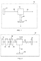
- Fig. 1 schematically illustrates an example of an apparatus 10.
- the apparatus 10 comprises a light source 12, a pixel control element 14 and an input transmission polarizer 16.
- the light source 12 is configured to output light as an input to the input transmission polarizer 16.
- the light source 12 may be/comprise any suitable light source 12 such as any suitable source of unpolarized light.
- the light source 12 may comprise one or more light emitting diodes (LEDs), one or more high pressure discharge lamps and/or one or more LED hybrid light sources and so on.
- the input transmission polarizer 16 is configured to polarize incident light 18 from the light source 12 into transmitted first and second light portions 20, 24.
- the first light portion 20 may have a first polarization and the second light portion 24 may have a second polarization orthogonal to the first polarization.
- the first and second polarizations may be considered first and second polarizations of the input transmission polarizer 16 as the input transmission polarizer 16 may be configured to polarize incident light into the first and second polarizations.
- the input transmission polarizer 16 may also be configured to direct polarized incident light, having the first polarization in a first direction and polarized incident light having the second polarization in a second direction, different to the first direction.
- the input transmission polarizer 16 is configured to provide the first light portion 20 as input to the pixel control element 14 and to output the second light portion 24 to provide the second light portion 24 for illumination
- the input transmission polarizer 16 may be/comprise any component or components configured to provide this functionality.
- the input transmission polarizer may be/comprise a polarizing beam splitter 28 (see, for example, Fig. 2 ), a polarizing plate beam splitter, a polarizing pellicle plate beam splitter and/or a diffractive beam splitter and so on.
- the pixel control element 14 may comprise a plurality of pixels and may be configured to utilize polarized light.
- the pixel control element 14 may rotate the polarization of the first light portion 20 depending on what is displayed on the pixels of the pixel control element 14.
- the polarization of the first light portion 20 may be rotated by 90° for pixels which are bright and by 0° for pixels which are dark.
- the pixel control element 14 may be a reflective pixel control element as illustrated in the example of Fig. 1 by the dashed arrow pointing from the pixel control element 14 back towards the input transmission polarizer 16 (see, for example, Fig. 3 ).
- the pixel control element 14 may comprise a reflective microdisplay such as a liquid crystal on silicone (LCOS) display and/or a digital light processing (DLP) display.
- LCOS liquid crystal on silicone
- DLP digital light processing
- the pixel control element 14 may be configured to transmit the first light portion 20 onwards as illustrated in the example of Fig. 1 by the dashed arrow pointing downwards from the pixel control element 14.
- the pixel control element 14 may comprise a transmissive microdisplay such as a transmissive liquid crystal microdisplay and/or a transmissive liquid crystal on silicone (LCOS) display.
- a transmissive microdisplay such as a transmissive liquid crystal microdisplay and/or a transmissive liquid crystal on silicone (LCOS) display.
- LCOS transmissive liquid crystal on silicone
- a microdisplay is a miniaturized display.
- a microdisplay may have a screen size less than 2 inches diagonally.
- a microdisplay may be, for example, suitable for use in a near eye display such as a head mounted display and/or a viewfinder.
- the apparatus 10 may comprise a number of additional components not illustrated in the example of Fig. 1 (see, for example, the example of Fig. 2 ).
- the light from the light source 12 is incident upon the input transmission polarizer 16.
- the input transmission polarizer 16 polarizes the incident light 18 from the light source 12 into a first light portion 20 and a second light portion 24.
- the first light portion 12 has a first polarization and, in the example of Fig. 1 , is directed downwards towards the pixel control element 14.
- the second light portion 24 may be provided for illumination.
- the second light portion 24 may be provided for illumination external to the apparatus 10 such as, as a flashlight and/or flash for a camera and/or other device.
- the camera and/or other device may form part of the apparatus 10 or may be separate from the apparatus 10.
- the second light portion 24 may be provided for any illumination function internal and/or external to the apparatus 10. This is advantageous as it provides for the polarization that is not utilized by the pixel control element 14 not being blocked and wasted as heat.
- the apparatus 10 may comprise one or more further components to further control the second light portion 24.
- the apparatus 10 may comprise one or more additional lenses to shape the external beam of light provided by the second light portion 24.
- the apparatus 10 may comprise additional component(s) to further direct and/or manipulate the second light portion 24.
- the first light portion 20 is provided to the pixel control element 14 as input.
- the pixel control element 14 selectively controls the polarization of the first light portion 20 according to the state of the pixels of the pixel control element 14. In some examples, the pixel control element 14 may reflect and/or transmit the first light portion 20 depending on the configuration of the pixel control element 14.
- the input transmission polarizer 16 may be located between the light source 12 and the pixel control element 14.
- the input transmission polarizer 16 may be physically located between the light source 12 and the pixel control element 14 and/or located between the light source 12 and the pixel control element 14 in the light path (see, for example, Fig. 1 ).
- the apparatus 10 may comprise a near-eye display.
- the apparatus 10 may comprise a head mounted display such as smart eye wear.
- the directions of the first and second light portions 20, 24 have been swapped. Accordingly, in the example of Fig. 2 the pixel control element 14 is located to the right of the input transmission polarizer 16.
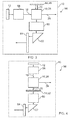
- the input transmission polarizer 16 is a polarizing beam splitter 28 and the apparatus 10 further comprises a polarization recycler 46, a polarization controller 36 and a control mechanism 30.
- the polarization controller 36 comprises a polarizer 38 and a controllable polarization rotator 40.
- the polarizer 38 may be configured to block and/or redirect and/or reflect the unselected polarization of light from the light source 12.
- the polarizer 38 may comprise any suitable component or components. For example, a wire-grid polarizer and so on.
- controllable polarization rotator 40 is configured to receive light from the polarizer 38 and to output light towards the polarizing beam splitter 28. In the example, the controllable polarization rotator 40 is configured to selectively rotate the polarization of the light from the polarizer 38.
- controllable polarization rotator 40 may be configured to controllably rotate the polarization of the light from the polarizer 38 from the first polarization of the polarizing beam splitter 28 to the second polarization of the polarizing beam splitter 28 or vice versa.
- the controllable polarization rotator 40 may also be configured to allow the light from the polarizer 38 to pass through without rotation of the polarization.
- the light from the polarizer 38 may not be in the first or second polarization of the polarizing beam splitter 28 and the controllable polarization rotator 40 may be configured to selectively rotate the polarization of light from the polarizer 38 into the first or second polarizations of the polarizing beam splitter 28.
- the polarization controller 36 which in the example of Fig. 2 comprises the polarizer 38 and the controllable polarization rotator 40, may be configured to controllably select in which polarization the light 18 is incident upon the polarizing beam splitter 28.
- the polarization controller 36 may be configured to select whether the light 18 incident upon the polarizing beam splitter 28 is in the first or second polarization of the polarizing beam splitter 28.
- the polarization controller 36 may therefore be configured to control whether light from the light source 12 is provided as the first light portion 20 or the second light portion 24 or how much light is provided in the first light portion 20 and the second light portion 24.
- the input transmission polarizer 16 which in the example of Fig. 2 is a polarizing beam splitter, may be configured to provide polarized incident light having the first polarization to the pixel control element 14 and to output polarized incident light having the second polarization for illumination.
- the polarization controller 36 may be configured to select, by controlling the polarization of light incident upon the input transmission polarizer 16, whether light from the light source is provided as the first light portion 20 to the pixel control element 14 and then for display or as the second light portion 24 for illumination.
- the controllable polarization rotator 40 may comprise any suitable component or components to controllably rotate the polarization of the light from the polarizer 38.
- the polarization rotator 40 may be controllable using an applied field such as an electric field.
- the controllable polarization rotator 40 may comprise a liquid crystal plate and/or a switchable waveplate such as a half wave waveplate and/or a lambda/4 switch where lambda refers to the wavelength of light from the light source 12.
- the polarization controller 36 may comprise any suitable component or components.
- the polarization controller 36 may comprise a plurality of different polarizers 38 that may be switched into the light path of light incident upon the input transmission polarizer 16 to selectively control the polarization of the light incident upon the input transmission polarizer 16.
- the polarization recycler 46 may be configured to receive light from the light source 12 and to provide light to the polarization controller 36, which in the example of Fig 2 comprises the polarizer 38 and the controllable polarization rotator 40.
- the polarization recycler 46 is also configured to receive returned light from the polarization controller 36, for example light having the polarization not transmitted by the polarizer 38, and to recycle at least a portion of the returned light.
- the polarization recycler 46 may recycle at least a portion of the returned light to have the selected polarization, for example light having the polarization transmitted by the polarizer 38.
- the polarization recycler 46 may be configured to maximize the amount of light from a light source 12 having a selected polarization and therefore the amount of light incident upon the polarizing beam splitter 18 having the selected polarization.
- the polarization recycler 46 and the polarization controller 36 may be configured to maximize the amount of light from the light source 12 provided as the second light portion 24 for illumination or the first light portion 20 to the pixel control element 14 and for display.
- the polarization recycler 46 may comprise any suitable component or components.
- an integrator light pipe or rod with polarization recycling implemented with, for example, a quarter wave plate and mirror.
- control mechanism 30 is configured to receive the second light portion 24 as input and to control how much of the second light portion 24 is provided for illumination.
- control mechanism 30 may be considered a light transmission controller, a controllable aperture and/or a light blocking apparatus.
- control mechanism 30 may be configured to control the transmission ratio of the second light portion 24.
- control mechanism 30 may be configured to block and/or absorb and/or redirect and/or reflect at least part of the second light portion 24.
- control mechanism 30 may be configured to transmit all or none of the second light portion 24 for illumination. In other examples, the control mechanism 30 may be configured to selectively control the transmission of the second light portion 24 on a continuous scale from 0% to an upper limit greater than 0%, for example 100%.
- the control mechanism 30 may comprise any suitable component or components.
- the control mechanism 30 may comprise a liquid crystal shutter such as an adjustable liquid crystal shutter and/or a mechanical shutter or aperture and so on.
- the light source 12 produces light which enters the polarization recycler 46.
- the light passes through the polarization recycler 46 to the polarizer 38.
- the polarizer 38 polarizes the light from the light source 12. In examples such as the example of Fig. 2 , the polarizer 38 polarizes the light from the light source 12 into the first polarization of the polarizing beam splitter 28.
- Light having the selected polarization passes to the controllable polarization rotator 40 and light having the unselected polarization is returned to the polarization recycler 46.
- the polarization recycler 46 recycles at least a portion of the returned light and outputs the recycled light to the polarizer 38.
- controllable polarization rotator 40 is controlled to either allow the light from the polarizer 38 to pass to the polarizing beam splitter 28 with the first polarization or to rotate the polarization of the light from the polarizer 38 to the second polarization of the polarizing beam splitter 28.
- the polarizing beam splitter 28 provides the light as the first light portion 20 as input to the pixel control element 14. That is, in examples where the incident light 18 upon the polarizing beam splitter 28 is polarized in the first polarization, the first light portion comprises all of the incident light 18.
- the polarizing beam splitter 28 When the polarization rotator 40 rotates the polarization of the light from the polarizer 38 to have the second polarization of the polarizing beam splitter and outputs light having the second polarization, the polarizing beam splitter 28 outputs the incident light 18 as the second light portion 24 for illumination. In examples where the incident light 18 upon the polarizing beam splitter 28 is polarized in the second polarization, the second light portion 24 comprises all of the incident light.
- control mechanism 30 may control the transmission ratio of the second light portion 24.
- the second light portion 24 may be used in some examples as a flashlight.
- the control mechanism 30 may control whether the flashlight is on or off and/or control brightness of the flashlight.
- the polarization controller 36 may be configured to control the polarization of the light from the light source 12 in synchronization with the pixel control element 14.
- the polarization controller 36 may be configured to control the polarization of the light from the light source 12 in synchronization with the duty cycle of the pixel control element 14.
- light may be provided as the first light portion 20 to the pixel control element 14 when the pixel control element 14 needs the input light but otherwise the light may be provided as the second light portion and output for illumination.
- the pixel control element 40 may operate without incident light all of the time.
- the pixel control element 14 may have a duty cycle of 40% or less which means that 60% of the time light from the light source 12 may be output for illumination.
- the polarization controller 36 may be controlled to provide light to the polarizing beam splitter 28 in the first polarization when the pixel control element 40 requires the light but otherwise may provide light in the second polarization to the polarizing beam splitter 28 to allow the light to be output as a second light portion 24 to be used for illumination.
- the polarization controller 36 may control the polarization of the light incident upon the input transmission polarizer 16 to control when the light is provided as the first light portion 20 or the second light portion 24.
- one or more of the components illustrated in Fig. 2 may be omitted.
- one or more of the polarization recycler 46, the polarizer 38, the controllable polarization rotator 40 and the control mechanism 30 may be omitted.
- the apparatus 10 may comprise a number of additional components not illustrated in the example of Fig. 2 .
- one or more of the components illustrated in the example of Fig. 2 may be integrated and/or combined with one or more components illustrated and/or additional components not illustrated in the example of Fig. 2 .
- FIG. 3 schematically illustrates a further example of an apparatus 10.
- the apparatus 10 comprises a near eye display 56.
- the apparatus 10 of Fig. 3 further comprises a light collimating and recycling lens set 58, image lenses 60, a mirror prism 62 and an exit pupil expander 64.
- the pixel control element comprises a reflective microdisplay.
- the reflective microdisplay 48 is a liquid crystal on silicone (LCOS) display.
- the light collimating and recycling lens set 58 is configured to receive light from the light source 12 and to provide light to the polarizing beam splitter 28.
- the light collimating and recycling lens set 58 is configured to collimate light from the light source 12 and to recycle light returned to it by other component(s) of the apparatus 10.
- the light collimating and recycling lens set 58 may comprise any suitable component or components.
- the image lenses 60 are configured to receive light from the polarizing beam splitter 28 and to adjust the light from the polarizing beam splitter 28.
- the image lenses 60 may project the image produced at the pixel control element 14 and/or may zoom the image produced at the pixel control element 14 and/or may adjust the focus of the image produced at the pixel control element 14 and so on.
- the image lenses 60 may comprise any suitable component or components.
- the mirror prism 62 is configured to receive light from the image lenses 60 and to redirect the light towards the exit pupil expander 64.
- the mirror prism 62 may comprise any suitable component or components.
- the light source 12 provides light to the light collimating and recycling lens set.
- the light passes through the light collimating and recycling lens set 58 to the polarizing beam splitter 28.
- the polarizing beam splitter polarizes the incident light 18 into transmitted first and second light portions 20, 24.
- the first light portion 20 having a first polarization is provided as input to the reflective microdisplay 48.
- the second light portion 24 having a second polarization orthogonal to the first polarization is output for illumination.
- At least part of the light in the first light portion 20 is reflected by the LCOS display.
- the polarization of the light reflected from each pixel is rotated between 0 and 90° depending on what is displayed on the LCOS pixels.
- the light passes through the image lenses 60 and is redirected by the mirror prism 62 into the exit pupil expander 64 which provides the light to an eye or eyes of a user.
- the image displayed on the reflective microdisplay is transmitted to an eye or eyes of the user.
- the polarized state of the second light portion 24, which is not used by the reflective microdisplay, is used for illumination and is not blocked and/or wasted.
- one or more of the components illustrated in Fig. 3 may be omitted.
- the apparatus 10 may comprise a number of additional components not illustrated in the example of Fig. 3 .
- Fig. 4 schematically illustrates a further example of an apparatus 10.
- the apparatus 10 comprises a near-eye display 56.
- the apparatus 10 comprises components described in relation to Fig. 3 . These components may be as described in relation to Fig. 3 .
- the pixel control element 14 comprises a transmissive microdisplay 52.
- the transmissive microdisplay 52 comprises a transmissive liquid crystal microdisplay.
- light is produced by the light source 12 and enters the light collimating and recycling lens set 58.
- the light passes through the light collimating and recycling lens set 58 to the polarizing beam splitter 28.
- the polarizing beam splitter 28 provides the first light portion as input to the transmissive microdisplay 14 and the second light portion is output to be provided for illumination.
- the first light portion 20 passes through the transmissive microdisplay 52.
- the pixels of the transmissive microdisplay 52 selectively rotate the polarization of the first light portion 20 depending upon what is displayed on the transmissive microdisplay 52.
- the light passes through the image lenses 60 and is redirected by the mirror prism 62 to the exit pupil expander 64.
- the exit pupil expander 64 provides the light to an eye or eyes of the user. In examples, such as the example of Fig. 4 , in this way, the image displayed on the transmissive microdisplay is transmitted to an eye or eyes of the user.
- the polarized state of the second light portion 24, which is not used by the transmissive microdisplay, is used for illumination and is not blocked and/or wasted.
- one or more of the components illustrated in Fig. 4 may be omitted.
- the apparatus 10 may comprise a number of additional components not illustrated in the example of Fig. 4 .
- one or more of the components illustrated in the example of Fig. 4 may be integrated and/or combined with one or more components illustrated and/or additional components not illustrated in the example of Fig. 4 .
- the use of the second light portion for illumination provide additional functionality to apparatuses such as near-eye displays 58 illustrated in the examples of Figs 3 and 4 at little or no extra cost.
- examples of the disclosure allow for a user to avoid wearing separate smart eyewear and head lamp, for example, which can be uncomfortable and difficult, or even impossible, to wear and operate together.
- Fig. 5 illustrates an example of a method 500.
- the light source 12 may be as described above and in relation to Figs. 1 and/or 2.
- a pixel control element 14 is provided.
- the pixel control element 14 may be any suitable pixel control element 14 and may be provided using any suitable method.
- the pixel control element 14 may be as described above in relation to Figs. 1 and/or 2.
- the input transmission polarizer may be configured to polarize incident light 18 from the light source 12 into transmitted first and second light portions 20, 24, wherein the first light portion 20 has a first polarization and the second light portion 24 has a second polarization wherein the first and second polarizations are orthogonal.
- the input transmission polarizer 16 may also be configured to provide the first light portion 20 as input to the pixel control element 14 and to output the second light portion 24 to provide the second light portion 24 for illumination.
- the input transmission polarizer 16 may be configured to polarize incident light 18 to simultaneously provide the first and second light portions 20, 24.
- the apparatus 10 may comprise a plurality of light sources 12.
- the light sources 12 may be the same or different light sources.
- 'component' may mean 'optical component'.
Landscapes
- Physics & Mathematics (AREA)
- General Physics & Mathematics (AREA)
- Optics & Photonics (AREA)
- Nonlinear Science (AREA)
- Polarising Elements (AREA)
Abstract
Description
- Examples of the disclosure relate to apparatuses and methods for providing light. For example, examples of the disclosure relate to apparatuses and methods for providing light in a display apparatus such as a near eye display apparatus.
- Some display apparatuses utilize polarized light. Such display apparatuses are arranged so that in operation they are provided with polarized light which may then, for example, be provided to an eye or eyes of a user.
- In some examples display apparatuses that utilize polarized light may form part of a near eye display such as a head mounted display.
- According to various, but not necessarily all, examples of the disclosure there is provided an apparatus comprising:
- a light source;
- a pixel control element; and
- an input transmission polarizer configured to:
- polarize incident light from the light source into transmitted first and second light portions,
- wherein the first light portion has a first polarization and the second light portion has a second polarization and wherein the first and second polarizations are orthogonal;
- to provide the first light portion as input to the pixel control element; and
- to output the second light portion to provide the second light portion for illumination.
- According to various, but not necessarily all, examples of the disclosure there is provided a method comprising:
- providing a light source;
- providing a pixel control element; and
- providing an input transmission polarizer configured to:
- polarize incident light from the light source into transmitted first and second light portions,
- wherein the first light portion has a first polarization and the second light portion has a second polarization and wherein the first and second polarizations are orthogonal;
- to provide the first light portion as input to the pixel control element; and
- to output the second light portion to provide the second light portion for illumination.
- According to various, but not necessarily all, examples of the disclosure there is provided an apparatus comprising:
- light providing means;
- pixel control means; and
- input transmission polarizing means for:
- polarizing incident light from the light source into transmitted first and second light portions,
- wherein the first light portion has a first polarization and the second light portion has a second polarization and wherein the first and second polarizations are orthogonal;
- providing the first light portion as input to the pixel control element; and
- outputting the second light portion to provide the second light portion for illumination.
- According to various, but not necessarily all, examples of the disclosure there is provided a method comprising:
- polarizing incident light from a light source into transmitted first and second light portions,
- wherein the first light portion has a first polarization and the second light portion has a second polarization and wherein the first and second polarizations are orthogonal;
- providing the first light portion as input to a pixel control element; and
- outputting the second light portion to provide the second light portion for illumination.
- According to various, but not necessarily all, examples of the disclosure, there is provided an apparatus comprising means for performing the method as described in the paragraph above.
- According to various, but not necessarily all, examples of the disclosure there is provided a method comprising:
- using a polarizing beam splitter to simultaneously polarize incident light from a light source into transmitted first and second light portions, wherein the first light portion has a first polarization and the second light portion has a second polarization and wherein the first and
- second polarizations are orthogonal;
- to provide the first light portion as input to a pixel control element; and
- to output the second light portion to provide the second light portion for illumination.
- According to various, but not necessarily all, examples of the disclosure there is provided an apparatus comprising means for performing the method as described in the paragraph above.
- For a better understanding of various examples that are useful for understanding the brief description, reference will now be made by way of example only to the accompanying drawings in which:
-
Fig. 1 illustrates an example of an apparatus; -
Fig. 2 illustrates an example of an apparatus; -
Fig. 3 illustrates an example of an apparatus; -
Fig. 4 illustrates an example of an apparatus; and -
Fig. 5 illustrates an example of a method. - Examples of the disclosure relate to providing light in an apparatus, which may for example comprise a display apparatus. In some examples unpolarized light from a light source is polarized into a first light portion having a first polarization and a second light portion having a second polarization orthogonal to the first polarization. The first light portion is provided to a pixel control element, configured to operate using polarized incident light, and then may be transmitted onwards to an eye or eyes of a user and the second light portion is provided for illumination. In some examples the second light portion may be provided for illumination external to the apparatus.
- In examples of the disclosure the second light portion having the second polarization that is not utilized by the pixel control element is not blocked and wasted but used for an illumination function. This provides the technical effect of, for example, an energy efficient apparatus.
-
Figures 1 to 4 illustrate anapparatus 10 comprising alight source 12; apixel control element 14; and aninput transmission polarizer 16 configured to: polarizeincident light 18 from thelight source 12 into transmitted first andsecond light portions first light portion 20 has a first polarization and thesecond light portion 24 has a second polarization and wherein the first and second polarizations are orthogonal; to provide thefirst light portion 20 as input to thepixel control element 14; and to output thesecond light portion 24 to provide thesecond light portion 24 for illumination. - In some examples, the
apparatus 10 may be for use in a near eye display. -
Fig. 5 illustrates amethod 500 comprising: providing alight source 12; providing apixel control element 14; and providing aninput transmission polarizer 16 configured to: polarizeincident light 18 from thelight source 12 into transmitted first andsecond light portions first light portion 20 has a first polarization and thesecond light portion 24 has a second polarization and wherein the first and second polarizations are orthogonal; to provide thefirst light portion 20 as input to thepixel control element 14; and to output thesecond light portion 24 to provide thesecond light portion 24 for illumination. -
Fig. 1 schematically illustrates an example of anapparatus 10. In the illustrated example, theapparatus 10 comprises alight source 12, apixel control element 14 and aninput transmission polarizer 16. - The
light source 12 is configured to output light as an input to theinput transmission polarizer 16. Thelight source 12 may be/comprise anysuitable light source 12 such as any suitable source of unpolarized light. For example, thelight source 12 may comprise one or more light emitting diodes (LEDs), one or more high pressure discharge lamps and/or one or more LED hybrid light sources and so on. - In the example of
Fig. 1 , theinput transmission polarizer 16 is configured to polarize incident light 18 from thelight source 12 into transmitted first and secondlight portions first light portion 20 may have a first polarization and the secondlight portion 24 may have a second polarization orthogonal to the first polarization. - The first and second polarizations may be considered first and second polarizations of the
input transmission polarizer 16 as theinput transmission polarizer 16 may be configured to polarize incident light into the first and second polarizations. - The
input transmission polarizer 16 may also be configured to direct polarized incident light, having the first polarization in a first direction and polarized incident light having the second polarization in a second direction, different to the first direction. - In the example of
Fig. 1 , theinput transmission polarizer 16 is configured to provide thefirst light portion 20 as input to thepixel control element 14 and to output the secondlight portion 24 to provide the secondlight portion 24 for illumination - In examples the
input transmission polarizer 16 may be/comprise any component or components configured to provide this functionality. For example the input transmission polarizer may be/comprise a polarizing beam splitter 28 (see, for example,Fig. 2 ), a polarizing plate beam splitter, a polarizing pellicle plate beam splitter and/or a diffractive beam splitter and so on. - The
pixel control element 14 may comprise a plurality of pixels and may be configured to utilize polarized light. - In examples such as the example of
Fig. 1 thepixel control element 14 is configured to receive thefirst light portion 20 from theinput transmission polarizer 16 and to selectively control the polarization of thefirst light portion 20 according to the state of pixels of thepixel control element 14. - For example the
pixel control element 14 may rotate the polarization of thefirst light portion 20 depending on what is displayed on the pixels of thepixel control element 14. In some examples, the polarization of thefirst light portion 20 may be rotated by 90° for pixels which are bright and by 0° for pixels which are dark. - In some examples, the
pixel control element 14 may be a reflective pixel control element as illustrated in the example ofFig. 1 by the dashed arrow pointing from thepixel control element 14 back towards the input transmission polarizer 16 (see, for example,Fig. 3 ). For example, thepixel control element 14 may comprise a reflective microdisplay such as a liquid crystal on silicone (LCOS) display and/or a digital light processing (DLP) display. - In some examples the
pixel control element 14 may be configured to transmit thefirst light portion 20 onwards as illustrated in the example ofFig. 1 by the dashed arrow pointing downwards from thepixel control element 14. - In some examples the
pixel control element 14 may comprise a transmissive microdisplay such as a transmissive liquid crystal microdisplay and/or a transmissive liquid crystal on silicone (LCOS) display. - As used herein a microdisplay is a miniaturized display. In some examples a microdisplay may have a screen size less than 2 inches diagonally. A microdisplay may be, for example, suitable for use in a near eye display such as a head mounted display and/or a viewfinder.
- In examples, the
apparatus 10 may comprise a number of additional components not illustrated in the example ofFig. 1 (see, for example, the example ofFig. 2 ). - In examples, there may be any number of intervening components between the components illustrated in the example of
Fig. 1 , including no intervening components. For example, there may be one or more components between thelight source 12 and theinput transmission polarizer 16. - However, in such examples, the
light source 12 is still considered to provide light to theinput transmission polarizer 16. That is, in some examples the light may be transmitted directly or indirectly between any of the components illustrated and described in the examples herein. - Additionally or alternatively one or more of the components illustrated in the example of
Fig. 1 may be integrated and/or combined with one or more components illustrated and/or additional components not illustrated in the example ofFig. 1 . - In use, the
light source 12 provides light to theinput transmission polarizer 16. This is illustrated in the example ofFig. 1 by the arrow from thelight source 12 to theinput transmission polarizer 16. The arrows illustrated in the figures are schematic illustrations of a light path. - The light from the
light source 12 is incident upon theinput transmission polarizer 16. Theinput transmission polarizer 16 polarizes the incident light 18 from thelight source 12 into afirst light portion 20 and a secondlight portion 24. - The
first light portion 12 has a first polarization and, in the example ofFig. 1 , is directed downwards towards thepixel control element 14. - The second
light portion 24 has a second polarization, orthogonal to the first polarization, and, in the example ofFig. 1 , is output straight through theinput transmission polarizer 16. This is illustrated in the example ofFig. 1 by the arrow to the right from theinput transmission polarizer 16. - In examples, the
first light portion 20 and secondlight portion 24 may be provided in any direction from theinput transmission polarizer 16. For example, thefirst light portion 20 may be provided in the direction of the second light portion inFig. 1 and vice versa (see for example,Fig. 2 ). In some examples, thefirst light portion 20 may be provided at a first angle from an arbitrary axis and the secondlight portion 24 may be provided at a second angle from the arbitrary axis, different to the first angle. The first and second angles may or may not be orthogonal to each other. - The second
light portion 24 may be provided for illumination. For example, the secondlight portion 24 may be provided for illumination external to theapparatus 10 such as, as a flashlight and/or flash for a camera and/or other device. In some examples, the camera and/or other device may form part of theapparatus 10 or may be separate from theapparatus 10. - In examples, the second
light portion 24 may be provided for any illumination function internal and/or external to theapparatus 10. This is advantageous as it provides for the polarization that is not utilized by thepixel control element 14 not being blocked and wasted as heat. - In some examples, the
apparatus 10 may comprise one or more further components to further control the secondlight portion 24. For example, theapparatus 10 may comprise one or more additional lenses to shape the external beam of light provided by the secondlight portion 24. Additionally, or alternatively theapparatus 10 may comprise additional component(s) to further direct and/or manipulate the secondlight portion 24. - In examples, such as that illustrated in
Fig. 1 thefirst light portion 20 is provided to thepixel control element 14 as input. - The
pixel control element 14 selectively controls the polarization of thefirst light portion 20 according to the state of the pixels of thepixel control element 14. In some examples, thepixel control element 14 may reflect and/or transmit thefirst light portion 20 depending on the configuration of thepixel control element 14. - In examples, the
input transmission polarizer 16 may be located between thelight source 12 and thepixel control element 14. Theinput transmission polarizer 16 may be physically located between thelight source 12 and thepixel control element 14 and/or located between thelight source 12 and thepixel control element 14 in the light path (see, for example,Fig. 1 ). - The
apparatus 10 may comprise a near-eye display. In examples, theapparatus 10 may comprise a head mounted display such as smart eye wear. -
Fig. 2 schematically illustrates a further example of anapparatus 10. In the example ofFig. 2 , theapparatus 10 comprises the components described above in relation to the example ofFig. 1 , and these components may be as described in the example ofFig. 1 . - In the example of
Fig. 2 , the directions of the first and secondlight portions Fig. 2 thepixel control element 14 is located to the right of theinput transmission polarizer 16. - In the example of
Fig. 2 , theinput transmission polarizer 16 is a polarizing beam splitter 28 and theapparatus 10 further comprises apolarization recycler 46, apolarization controller 36 and acontrol mechanism 30. In the example ofFig. 2 , thepolarization controller 36 comprises apolarizer 38 and acontrollable polarization rotator 40. - The
polarization controller 36 may be configured to receive light from thelight source 12 as an input and to selectively output light having the first or second polarization of the polarizing beam splitter 28 as an input to theinput transmission polarizer 16. - In examples, such as the example of
Fig. 2 , thepolarizer 38 is configured to polarize light from thelight source 12 prior to the light from thelight source 12 being incident upon the polarizing beam splitter 28. Thepolarizer 38 may be considered a prepolarizer, initial polarizer and/or further polarizer. - The
polarizer 38 may be configured to polarize light from thelight source 12 into any polarization state. For example, thepolarizer 38 may be configured to polarize light from thelight source 12 into the first or second polarization of the polarizing beam splitter 28. - In examples, the
polarizer 38 may be configured to block and/or redirect and/or reflect the unselected polarization of light from thelight source 12. - The
polarizer 38 may comprise any suitable component or components. For example, a wire-grid polarizer and so on. - In the example of
Fig. 2 , thecontrollable polarization rotator 40 is configured to receive light from thepolarizer 38 and to output light towards the polarizing beam splitter 28. In the example, thecontrollable polarization rotator 40 is configured to selectively rotate the polarization of the light from thepolarizer 38. - For example, the
controllable polarization rotator 40 may be configured to controllably rotate the polarization of the light from thepolarizer 38 from the first polarization of the polarizing beam splitter 28 to the second polarization of the polarizing beam splitter 28 or vice versa. - The
controllable polarization rotator 40 may also be configured to allow the light from thepolarizer 38 to pass through without rotation of the polarization. - In some examples, the light from the
polarizer 38 may not be in the first or second polarization of the polarizing beam splitter 28 and thecontrollable polarization rotator 40 may be configured to selectively rotate the polarization of light from thepolarizer 38 into the first or second polarizations of the polarizing beam splitter 28. - The
polarization controller 36, which in the example ofFig. 2 comprises thepolarizer 38 and thecontrollable polarization rotator 40, may be configured to controllably select in which polarization the light 18 is incident upon the polarizing beam splitter 28. For example, thepolarization controller 36 may be configured to select whether the light 18 incident upon the polarizing beam splitter 28 is in the first or second polarization of the polarizing beam splitter 28. Thepolarization controller 36 may therefore be configured to control whether light from thelight source 12 is provided as thefirst light portion 20 or the secondlight portion 24 or how much light is provided in thefirst light portion 20 and the secondlight portion 24. This is because theinput transmission polarizer 16, which in the example ofFig. 2 is a polarizing beam splitter, may be configured to provide polarized incident light having the first polarization to thepixel control element 14 and to output polarized incident light having the second polarization for illumination. - In examples, the
polarization controller 36 may be configured to select, by controlling the polarization of light incident upon theinput transmission polarizer 16, whether light from the light source is provided as thefirst light portion 20 to thepixel control element 14 and then for display or as the secondlight portion 24 for illumination. - The
controllable polarization rotator 40 may comprise any suitable component or components to controllably rotate the polarization of the light from thepolarizer 38. In some examples thepolarization rotator 40 may be controllable using an applied field such as an electric field. For example, thecontrollable polarization rotator 40 may comprise a liquid crystal plate and/or a switchable waveplate such as a half wave waveplate and/or a lambda/4 switch where lambda refers to the wavelength of light from thelight source 12. - In examples the
polarization controller 36 may comprise any suitable component or components. For example thepolarization controller 36 may comprise a plurality ofdifferent polarizers 38 that may be switched into the light path of light incident upon theinput transmission polarizer 16 to selectively control the polarization of the light incident upon theinput transmission polarizer 16. - The
polarization recycler 46 may be configured to receive light from thelight source 12 and to provide light to thepolarization controller 36, which in the example ofFig 2 comprises thepolarizer 38 and thecontrollable polarization rotator 40. - In some examples, the
polarization recycler 46 is also configured to receive returned light from thepolarization controller 36, for example light having the polarization not transmitted by thepolarizer 38, and to recycle at least a portion of the returned light. For example thepolarization recycler 46 may recycle at least a portion of the returned light to have the selected polarization, for example light having the polarization transmitted by thepolarizer 38. - The
polarization recycler 46 may be configured to maximize the amount of light from alight source 12 having a selected polarization and therefore the amount of light incident upon thepolarizing beam splitter 18 having the selected polarization. - In examples, the
polarization recycler 46 and thepolarization controller 36 may be configured to maximize the amount of light from thelight source 12 provided as the secondlight portion 24 for illumination or thefirst light portion 20 to thepixel control element 14 and for display. - In examples, the
polarization recycler 46 may comprise any suitable component or components. For example an integrator light pipe or rod with polarization recycling implemented with, for example, a quarter wave plate and mirror. - In some examples, the
control mechanism 30 is configured to receive the secondlight portion 24 as input and to control how much of the secondlight portion 24 is provided for illumination. In examples thecontrol mechanism 30 may be considered a light transmission controller, a controllable aperture and/or a light blocking apparatus. - In some examples, the
control mechanism 30 may be configured to control the transmission ratio of the secondlight portion 24. For example, thecontrol mechanism 30 may be configured to block and/or absorb and/or redirect and/or reflect at least part of the secondlight portion 24. - In some examples, the
control mechanism 30 may be configured to transmit all or none of the secondlight portion 24 for illumination. In other examples, thecontrol mechanism 30 may be configured to selectively control the transmission of the secondlight portion 24 on a continuous scale from 0% to an upper limit greater than 0%, for example 100%. - The
control mechanism 30 may comprise any suitable component or components. For example, thecontrol mechanism 30 may comprise a liquid crystal shutter such as an adjustable liquid crystal shutter and/or a mechanical shutter or aperture and so on. - In use, the
light source 12 produces light which enters thepolarization recycler 46. The light passes through thepolarization recycler 46 to thepolarizer 38. - The
polarizer 38 polarizes the light from thelight source 12. In examples such as the example ofFig. 2 , thepolarizer 38 polarizes the light from thelight source 12 into the first polarization of the polarizing beam splitter 28. - Light having the selected polarization passes to the
controllable polarization rotator 40 and light having the unselected polarization is returned to thepolarization recycler 46. - The
polarization recycler 46 recycles at least a portion of the returned light and outputs the recycled light to thepolarizer 38. - In examples such as the example of
Fig. 2 , thecontrollable polarization rotator 40 is controlled to either allow the light from thepolarizer 38 to pass to the polarizing beam splitter 28 with the first polarization or to rotate the polarization of the light from thepolarizer 38 to the second polarization of the polarizing beam splitter 28. - When the
controllable polarization rotator 40 outputs light with the first polarization, the polarizing beam splitter 28 provides the light as thefirst light portion 20 as input to thepixel control element 14. That is, in examples where theincident light 18 upon the polarizing beam splitter 28 is polarized in the first polarization, the first light portion comprises all of theincident light 18. - When the
polarization rotator 40 rotates the polarization of the light from thepolarizer 38 to have the second polarization of the polarizing beam splitter and outputs light having the second polarization, the polarizing beam splitter 28 outputs the incident light 18 as the secondlight portion 24 for illumination. In examples where theincident light 18 upon the polarizing beam splitter 28 is polarized in the second polarization, the secondlight portion 24 comprises all of the incident light. - In some examples, when light is output from the polarizing beam splitter 28 as a second
light portion 24, thecontrol mechanism 30 may control the transmission ratio of the secondlight portion 24. - For example, the second
light portion 24 may be used in some examples as a flashlight. In such examples, thecontrol mechanism 30 may control whether the flashlight is on or off and/or control brightness of the flashlight. - In some examples, the
polarization controller 36 may be configured to control the polarization of the light from thelight source 12 in synchronization with thepixel control element 14. For example thepolarization controller 36 may be configured to control the polarization of the light from thelight source 12 in synchronization with the duty cycle of thepixel control element 14. - That is, in some examples light may be provided as the
first light portion 20 to thepixel control element 14 when thepixel control element 14 needs the input light but otherwise the light may be provided as the second light portion and output for illumination. - In some examples, the
pixel control element 40 may operate without incident light all of the time. For example, thepixel control element 14 may have a duty cycle of 40% or less which means that 60% of the time light from thelight source 12 may be output for illumination. - The
polarization controller 36 may be controlled to provide light to the polarizing beam splitter 28 in the first polarization when thepixel control element 40 requires the light but otherwise may provide light in the second polarization to the polarizing beam splitter 28 to allow the light to be output as a secondlight portion 24 to be used for illumination. - In general, the
polarization controller 36 may control the polarization of the light incident upon theinput transmission polarizer 16 to control when the light is provided as thefirst light portion 20 or the secondlight portion 24. - In some examples, one or more of the components illustrated in
Fig. 2 may be omitted. For example, one or more of thepolarization recycler 46, thepolarizer 38, thecontrollable polarization rotator 40 and thecontrol mechanism 30 may be omitted. - In examples, the
apparatus 10 may comprise a number of additional components not illustrated in the example ofFig. 2 . - In examples, there may be any number of intervening components between the components illustrated in the example of
Fig. 2 , including no intervening components. - Additionally or alternatively one or more of the components illustrated in the example of
Fig. 2 may be integrated and/or combined with one or more components illustrated and/or additional components not illustrated in the example ofFig. 2 . -
Fig. 3 schematically illustrates a further example of anapparatus 10. - In the example of
Fig. 3 , theapparatus 10 comprises some components of theapparatus 10 described in relation toFigs. 1 and 2 and comprises additional components. The components ofFig. 3 may be as described above in relation toFigs. 1 and/or 2. - In the example of
Fig. 3 , theapparatus 10 comprises anear eye display 56. Theapparatus 10 ofFig. 3 further comprises a light collimating and recycling lens set 58,image lenses 60, amirror prism 62 and anexit pupil expander 64. - In the example of
Fig. 3 , the pixel control element comprises a reflective microdisplay. InFig. 3 the reflective microdisplay 48 is a liquid crystal on silicone (LCOS) display. - In
Fig. 3 , theinput transmission polarizer 16 comprises a polarizing beam splitter 28. - The light collimating and recycling lens set 58 is configured to receive light from the
light source 12 and to provide light to the polarizing beam splitter 28. The light collimating and recycling lens set 58 is configured to collimate light from thelight source 12 and to recycle light returned to it by other component(s) of theapparatus 10. The light collimating and recycling lens set 58 may comprise any suitable component or components. - In examples, such as the example of
Fig. 3 , theimage lenses 60 are configured to receive light from the polarizing beam splitter 28 and to adjust the light from the polarizing beam splitter 28. For example, theimage lenses 60 may project the image produced at thepixel control element 14 and/or may zoom the image produced at thepixel control element 14 and/or may adjust the focus of the image produced at thepixel control element 14 and so on. Theimage lenses 60 may comprise any suitable component or components. - The
mirror prism 62 is configured to receive light from theimage lenses 60 and to redirect the light towards theexit pupil expander 64. Themirror prism 62 may comprise any suitable component or components. - The
exit pupil expander 64 is configured to receive light from themirror prism 62 and to provide light to an eye or eyes of a user. Theexit pupil expander 64 may comprise any suitable component or components. - In use, the
light source 12 provides light to the light collimating and recycling lens set. The light passes through the light collimating and recycling lens set 58 to the polarizing beam splitter 28. The polarizing beam splitter polarizes the incident light 18 into transmitted first and secondlight portions first light portion 20 having a first polarization is provided as input to the reflective microdisplay 48. - The second
light portion 24 having a second polarization orthogonal to the first polarization is output for illumination. - In examples, such as the example of
Fig. 3 , at least part of the light in thefirst light portion 20 is reflected by the LCOS display. The polarization of the light reflected from each pixel is rotated between 0 and 90° depending on what is displayed on the LCOS pixels. - In the example of
Fig. 3 , light from a pixel having polarization rotated by 90° passes through the polarizing beam splitter and enters into theimage lenses 60. Light from pixels having polarization rotated by 0° is reflected back towards thelight source 12 by the polarizing beam splitter 28 and may be recycled in the light collimating and recycling lens set 58. - The light passes through the
image lenses 60 and is redirected by themirror prism 62 into theexit pupil expander 64 which provides the light to an eye or eyes of a user. - In examples, such as the example of
Fig. 3 , in this way, the image displayed on the reflective microdisplay is transmitted to an eye or eyes of the user. - In addition, the polarized state of the second
light portion 24, which is not used by the reflective microdisplay, is used for illumination and is not blocked and/or wasted. - In some examples, one or more of the components illustrated in
Fig. 3 may be omitted. - In examples, the
apparatus 10 may comprise a number of additional components not illustrated in the example ofFig. 3 . - In examples, there may be any number of intervening components between the components illustrated in the example of
Fig. 3 , including no intervening components. Additionally or alternatively one or more of the components illustrated in the example ofFig. 3 may be integrated and/or combined with one or more components illustrated and/or additional components not illustrated in the example ofFig. 3 . -
Fig. 4 schematically illustrates a further example of anapparatus 10. In the example ofFig. 4 theapparatus 10 comprises a near-eye display 56. - In the example of
Fig. 4 , theapparatus 10 comprises components described in relation toFig. 3 . These components may be as described in relation toFig. 3 . - In the example of
Fig. 4 , thepixel control element 14 comprises a transmissive microdisplay 52. In the example ofFig. 4 , the transmissive microdisplay 52 comprises a transmissive liquid crystal microdisplay. - In use, light is produced by the
light source 12 and enters the light collimating and recycling lens set 58. - The light passes through the light collimating and recycling lens set 58 to the polarizing beam splitter 28. The polarizing beam splitter 28 provides the first light portion as input to the
transmissive microdisplay 14 and the second light portion is output to be provided for illumination. - The
first light portion 20 passes through the transmissive microdisplay 52. The pixels of the transmissive microdisplay 52 selectively rotate the polarization of thefirst light portion 20 depending upon what is displayed on the transmissive microdisplay 52. - The light passes through the
image lenses 60 and is redirected by themirror prism 62 to theexit pupil expander 64. - The
exit pupil expander 64 provides the light to an eye or eyes of the user. In examples, such as the example ofFig. 4 , in this way, the image displayed on the transmissive microdisplay is transmitted to an eye or eyes of the user. - In addition, the polarized state of the second
light portion 24, which is not used by the transmissive microdisplay, is used for illumination and is not blocked and/or wasted. - In some examples, one or more of the components illustrated in
Fig. 4 may be omitted. - In examples, the
apparatus 10 may comprise a number of additional components not illustrated in the example ofFig. 4 . - In examples, there may be any number of intervening components between the components illustrated in the example of
Fig. 4 , including no intervening components. - Additionally or alternatively one or more of the components illustrated in the example of
Fig. 4 may be integrated and/or combined with one or more components illustrated and/or additional components not illustrated in the example ofFig. 4 . - The use of the second light portion for illumination provide additional functionality to apparatuses such as near-eye displays 58 illustrated in the examples of
Figs 3 and 4 at little or no extra cost. - In addition, examples of the disclosure allow for a user to avoid wearing separate smart eyewear and head lamp, for example, which can be uncomfortable and difficult, or even impossible, to wear and operate together.
-
Fig. 5 illustrates an example of amethod 500. - At block 502 a light source is provided. The
light source 12 may be any suitablelight source 12 and may be provided using any suitable method. - For example, the
light source 12 may be as described above and in relation toFigs. 1 and/or 2. - At block 504 a
pixel control element 14 is provided. - The
pixel control element 14 may be any suitablepixel control element 14 and may be provided using any suitable method. For example, thepixel control element 14 may be as described above in relation toFigs. 1 and/or 2. - At
block 506 aninput transmission polarizer 16 is provided. - The
input transmission polarizer 16 may be any suitableinput transmission polarizer 16 and may be provided by any suitable method. For example, theinput transmission polarizer 16 may be as described above in relation toFigs. 1 and/or 2. - The input transmission polarizer may be configured to polarize incident light 18 from the
light source 12 into transmitted first and secondlight portions first light portion 20 has a first polarization and the secondlight portion 24 has a second polarization wherein the first and second polarizations are orthogonal. Theinput transmission polarizer 16 may also be configured to provide thefirst light portion 20 as input to thepixel control element 14 and to output the secondlight portion 24 to provide the secondlight portion 24 for illumination. - The
input transmission polarizer 16 may be configured to polarize incident light 18 to simultaneously provide the first and secondlight portions - In some examples, the
method 500 may further comprise providing apolarization recycler 46 and/or apolarization controller 36 and/or acontrol mechanism 30. Thepolarization recycler 46 and/orpolarization controller 36 and/orcontrol mechanism 30 may comprise any suitable component or components and may be provided by any suitable method. For example, thepolarization recycler 46 and/orpolarization controller 36 and/orcontrol mechanism 30 may be as described above in relation toFig. 2 . - In some examples, the method may comprise providing one or more of the components illustrated in the examples of
Fig. 3 and/or 4. The components may be provided using any suitable method. - The blocks illustrated in
Fig 5 may represent steps in a method. The illustration of a particular order to the blocks does not necessarily imply that there is a required or preferred order for the blocks and the order and arrangement of the block may be varied. Furthermore, it may be possible for one or more blocks to be omitted. - Where a structural feature has been described, it may be replaced by means for performing one or more of the functions of the structural feature whether that function or those functions are explicitly or implicitly described.
- The term 'comprise' is used in this document with an inclusive not an exclusive meaning. That is any reference to X comprising Y indicates that X may comprise only one Y or may comprise more than one Y. If it is intended to use 'comprise' with an exclusive meaning then it will be made clear in the context by referring to "comprising only one.." or by using "consisting".
- In this brief description, reference has been made to various examples. The description of features or functions in relation to an example indicates that those features or functions are present in that example. The use of the term 'example' or 'for example' or 'may' in the text denotes, whether explicitly stated or not, that such features or functions are present in at least the described example, whether described as an example or not, and that they can be, but are not necessarily, present in some of or all other examples. Thus 'example', 'for example' or 'may' refers to a particular instance in a class of examples. A property of the instance can be a property of only that instance or a property of the class or a property of a sub-class of the class that includes some but not all of the instances in the class. It is therefore implicitly disclosed that a features described with reference to one example but not with reference to another example, can where possible be used in that other example but does not necessarily have to be used in that other example.
- Although examples of the disclosure have been described in the preceding paragraphs with reference to various examples, it should be appreciated that modifications to the examples given can be made without departing from the scope of the invention as claimed. For example, the
apparatus 10 may comprise a plurality oflight sources 12. Thelight sources 12 may be the same or different light sources. - Additionally or alternatively the
apparatus 10 may comprise a plurality ofpixel control elements 14. Thepixel control elements 14 may be the same or different pixel control elements. - As used herein 'all' may mean 'substantially all'.
- As used herein 'component' may mean 'optical component'.
- Features described in the preceding description may be used in combinations other than the combinations explicitly described.
- Although functions have been described with reference to certain features, those functions may be performable by other features whether described or not.
- Although features have been described with reference to certain embodiments, those features may also be present in other embodiments whether described or not.
- Whilst endeavoring in the foregoing specification to draw attention to those features of the disclosure believed to be of particular importance it should be understood that the Applicant claims protection in respect of any patentable feature or combination of features hereinbefore referred to and/or shown in the drawings whether or not particular emphasis has been placed thereon.
Claims (15)
- An apparatus comprising:a light source;a pixel control element; andan input transmission polarizer configured to:polarize incident light from the light source into transmitted first and second light portions, wherein the first light portion has a first polarization and the second light portion has a second polarization and wherein the first and second polarizations are orthogonal;to provide the first light portion as input to the pixel control element; andto output the second light portion to provide the second light portion for illumination.
- An apparatus as claimed in claim 1, wherein the input transmission polarizer comprises a polarizing beam splitter.
- An apparatus as claimed in claim 1 or 2, wherein the input transmission polarizer is located between the light source and the pixel control element.
- An apparatus as claimed in any preceding claim, wherein the second light portion is output for illumination external to the apparatus.
- An apparatus as claimed in any preceding claim further comprising a control mechanism configured to receive the second light portion as an input and to control the transmission ratio of the second light portion.
- An apparatus as claimed in claim 5 wherein the control mechanism comprises a liquid crystal shutter.
- An apparatus as claimed in any preceding claim, further comprising a polarization controller configured to receive light from the light source as an input and to selectively output light having the first or second polarization as an input to the input transmission polarizer.
- An apparatus as claimed in claim 7, wherein the polarization controller comprises a polarizer and a controllable polarization rotator.
- An apparatus as claimed in claim 8, wherein the polarization rotator comprises a liquid crystal plate.
- An apparatus as claimed in any of claims 7, 8 or 9 wherein the polarization controller is configured to be controlled in synchronisation with the duty cycle of the pixel control element.
- An apparatus as claimed in any of claims 8, 9 or 10 further comprising a polarization recycler configured to receive light returned from the polarization controller and to recycle at least a portion of the returned light and output the recycled light to the polarization controller.
- An apparatus as claimed in any preceding claim wherein the pixel control element comprises a reflective microdisplay.
- An apparatus as claimed in any of claims 1 to 11, wherein the pixel control element comprises a transmissive microdisplay.
- An apparatus as claimed in any preceding claim, wherein the apparatus comprises a near-eye display.
- A method comprising:providing a light source;providing a pixel control element; andproviding an input transmission polarizer configured to:polarize incident light from the light source into transmitted first and second light portions, wherein the first light portion has a first polarization and the second light portion has a second polarization and wherein the first and second polarizations are orthogonal;to provide the first light portion as input to the pixel control element; andto output the second light portion to provide the second light portion for illumination.
Priority Applications (4)
| Application Number | Priority Date | Filing Date | Title |
|---|---|---|---|
| PL15156064T PL3059631T3 (en) | 2015-02-23 | 2015-02-23 | Apparatuses and methods for providing light |
| EP15156064.6A EP3059631B1 (en) | 2015-02-23 | 2015-02-23 | Apparatuses and methods for providing light |
| US15/552,659 US10209611B2 (en) | 2015-02-23 | 2016-02-05 | Apparatuses and methods for providing light |
| PCT/FI2016/050073 WO2016135376A1 (en) | 2015-02-23 | 2016-02-05 | Apparatuses and methods for providing light |
Applications Claiming Priority (1)
| Application Number | Priority Date | Filing Date | Title |
|---|---|---|---|
| EP15156064.6A EP3059631B1 (en) | 2015-02-23 | 2015-02-23 | Apparatuses and methods for providing light |
Publications (2)
| Publication Number | Publication Date |
|---|---|
| EP3059631A1 true EP3059631A1 (en) | 2016-08-24 |
| EP3059631B1 EP3059631B1 (en) | 2018-01-03 |
Family
ID=52633072
Family Applications (1)
| Application Number | Title | Priority Date | Filing Date |
|---|---|---|---|
| EP15156064.6A Active EP3059631B1 (en) | 2015-02-23 | 2015-02-23 | Apparatuses and methods for providing light |
Country Status (4)
| Country | Link |
|---|---|
| US (1) | US10209611B2 (en) |
| EP (1) | EP3059631B1 (en) |
| PL (1) | PL3059631T3 (en) |
| WO (1) | WO2016135376A1 (en) |
Families Citing this family (3)
| Publication number | Priority date | Publication date | Assignee | Title |
|---|---|---|---|---|
| EP3054339B1 (en) * | 2015-02-09 | 2019-06-26 | Nokia Technologies OY | A display apparatus |
| US20230368474A1 (en) * | 2022-03-19 | 2023-11-16 | Auroratech Company | Lightguide-type eyepiece for augmented reality headsets with improved field-of-view |
| US20230324688A1 (en) * | 2022-04-12 | 2023-10-12 | Auroratech Company | Ar headset optical system with several display sources |
Citations (4)
| Publication number | Priority date | Publication date | Assignee | Title |
|---|---|---|---|---|
| JPH09265070A (en) * | 1996-03-28 | 1997-10-07 | Canon Inc | 3D image display device |
| EP1098537A2 (en) * | 1999-11-06 | 2001-05-09 | SAMSUNG ELECTRONICS Co. Ltd. | Projection display device using two liquid crystal display panels |
| US20100110383A1 (en) * | 2008-11-06 | 2010-05-06 | Deming Tang | Optical projection engine device |
| US20110273906A1 (en) * | 2010-04-16 | 2011-11-10 | Anthony John Nichol | Front illumination device comprising a film-based lightguide |
Family Cites Families (6)
| Publication number | Priority date | Publication date | Assignee | Title |
|---|---|---|---|---|
| US20080018558A1 (en) * | 2006-04-04 | 2008-01-24 | Microvision, Inc. | Electronic display with photoluminescent wavelength conversion |
| CN101377572A (en) * | 2007-08-28 | 2009-03-04 | 鸿富锦精密工业(深圳)有限公司 | Stereo projection optical system |
| US8152313B2 (en) * | 2008-05-09 | 2012-04-10 | Sanyo Electric Co., Ltd. | Projection display device that displaces an optical position of an imager in conjunction with a focus adjustment |
| JP5669211B2 (en) * | 2009-03-26 | 2015-02-12 | Necディスプレイソリューションズ株式会社 | Projector and control method thereof |
| JP5494678B2 (en) * | 2011-02-17 | 2014-05-21 | 株式会社ニコン | Illumination optical system and projector apparatus |
| JP5762086B2 (en) * | 2011-03-31 | 2015-08-12 | キヤノン株式会社 | Polarization separation element and image projection apparatus |
-
2015
- 2015-02-23 EP EP15156064.6A patent/EP3059631B1/en active Active
- 2015-02-23 PL PL15156064T patent/PL3059631T3/en unknown
-
2016
- 2016-02-05 US US15/552,659 patent/US10209611B2/en active Active
- 2016-02-05 WO PCT/FI2016/050073 patent/WO2016135376A1/en not_active Ceased
Patent Citations (4)
| Publication number | Priority date | Publication date | Assignee | Title |
|---|---|---|---|---|
| JPH09265070A (en) * | 1996-03-28 | 1997-10-07 | Canon Inc | 3D image display device |
| EP1098537A2 (en) * | 1999-11-06 | 2001-05-09 | SAMSUNG ELECTRONICS Co. Ltd. | Projection display device using two liquid crystal display panels |
| US20100110383A1 (en) * | 2008-11-06 | 2010-05-06 | Deming Tang | Optical projection engine device |
| US20110273906A1 (en) * | 2010-04-16 | 2011-11-10 | Anthony John Nichol | Front illumination device comprising a film-based lightguide |
Also Published As
| Publication number | Publication date |
|---|---|
| EP3059631B1 (en) | 2018-01-03 |
| PL3059631T3 (en) | 2018-06-29 |
| US20180046070A1 (en) | 2018-02-15 |
| US10209611B2 (en) | 2019-02-19 |
| WO2016135376A1 (en) | 2016-09-01 |
Similar Documents
| Publication | Publication Date | Title |
|---|---|---|
| CN112654902B (en) | Head Mounted Display (HMD) with spatially varying phase shifter optics | |
| WO2016060119A1 (en) | Head-up display device | |
| CN104067334A (en) | Adaptive brightness control of head mounted display | |
| CN102385230B (en) | Light source system and projection device including the light source system | |
| CN103149780A (en) | Projection apparatus | |
| US10690926B1 (en) | Near-eye augmented reality device | |
| US10209611B2 (en) | Apparatuses and methods for providing light | |
| JP5631235B2 (en) | Transmitted light selection device, stereoscopic image display device, and stereoscopic image display method | |
| CN102411252A (en) | Display device | |
| US8888292B2 (en) | Projection apparatus for providing multiple viewing angle images | |
| JP2016161746A (en) | Image display device, projector, and transmissive display device | |
| US9104048B2 (en) | Three dimensional image projector with single modulator | |
| WO2013062930A1 (en) | Tilted dichroic polarized color combiner | |
| US8992024B2 (en) | Three dimensional image projector with circular light polarization | |
| KR100909274B1 (en) | Stereoscopic projection system and device for stereoscopic projection | |
| JP2015049272A (en) | Projection type display device | |
| US9122068B2 (en) | Polarization converting element group for projection apparatus and projection apparatus | |
| US8944604B2 (en) | Three dimensional image projector with dual light modulators | |
| US20250060588A1 (en) | Display system for providing high contrast ratio and reducing rainbow effect | |
| CN102591127B (en) | Projector and stereoscopic image system | |
| WO2025042793A1 (en) | Display system for providing high contrast ratio and reducing rainbow effect | |
| CN102591028A (en) | Projector and stereoscopic image system | |
| RU2008148112A (en) | METHOD FOR FORMING STEREO SPACE AND DEVICE FOR ITS IMPLEMENTATION | |
| WO2015060740A1 (en) | 3d-projector with lcd-shutters and dlp as a beam combiner |
Legal Events
| Date | Code | Title | Description |
|---|---|---|---|
| PUAI | Public reference made under article 153(3) epc to a published international application that has entered the european phase |
Free format text: ORIGINAL CODE: 0009012 |
|
| AK | Designated contracting states |
Kind code of ref document: A1 Designated state(s): AL AT BE BG CH CY CZ DE DK EE ES FI FR GB GR HR HU IE IS IT LI LT LU LV MC MK MT NL NO PL PT RO RS SE SI SK SM TR |
|
| AX | Request for extension of the european patent |
Extension state: BA ME |
|
| 17P | Request for examination filed |
Effective date: 20170222 |
|
| RBV | Designated contracting states (corrected) |
Designated state(s): AL AT BE BG CH CY CZ DE DK EE ES FI FR GB GR HR HU IE IS IT LI LT LU LV MC MK MT NL NO PL PT RO RS SE SI SK SM TR |
|
| GRAP | Despatch of communication of intention to grant a patent |
Free format text: ORIGINAL CODE: EPIDOSNIGR1 |
|
| INTG | Intention to grant announced |
Effective date: 20170818 |
|
| GRAS | Grant fee paid |
Free format text: ORIGINAL CODE: EPIDOSNIGR3 |
|
| GRAA | (expected) grant |
Free format text: ORIGINAL CODE: 0009210 |
|
| AK | Designated contracting states |
Kind code of ref document: B1 Designated state(s): AL AT BE BG CH CY CZ DE DK EE ES FI FR GB GR HR HU IE IS IT LI LT LU LV MC MK MT NL NO PL PT RO RS SE SI SK SM TR |
|
| REG | Reference to a national code |
Ref country code: GB Ref legal event code: FG4D |
|
| REG | Reference to a national code |
Ref country code: CH Ref legal event code: EP Ref country code: AT Ref legal event code: REF Ref document number: 960822 Country of ref document: AT Kind code of ref document: T Effective date: 20180115 |
|
| REG | Reference to a national code |
Ref country code: IE Ref legal event code: FG4D |
|
| REG | Reference to a national code |
Ref country code: DE Ref legal event code: R096 Ref document number: 602015007074 Country of ref document: DE |
|
| REG | Reference to a national code |
Ref country code: NL Ref legal event code: MP Effective date: 20180103 |
|
| REG | Reference to a national code |
Ref country code: LT Ref legal event code: MG4D |
|
| REG | Reference to a national code |
Ref country code: AT Ref legal event code: MK05 Ref document number: 960822 Country of ref document: AT Kind code of ref document: T Effective date: 20180103 |
|
| PG25 | Lapsed in a contracting state [announced via postgrant information from national office to epo] |
Ref country code: NL Free format text: LAPSE BECAUSE OF FAILURE TO SUBMIT A TRANSLATION OF THE DESCRIPTION OR TO PAY THE FEE WITHIN THE PRESCRIBED TIME-LIMIT Effective date: 20180103 |
|
| PG25 | Lapsed in a contracting state [announced via postgrant information from national office to epo] |
Ref country code: ES Free format text: LAPSE BECAUSE OF FAILURE TO SUBMIT A TRANSLATION OF THE DESCRIPTION OR TO PAY THE FEE WITHIN THE PRESCRIBED TIME-LIMIT Effective date: 20180103 Ref country code: CY Free format text: LAPSE BECAUSE OF FAILURE TO SUBMIT A TRANSLATION OF THE DESCRIPTION OR TO PAY THE FEE WITHIN THE PRESCRIBED TIME-LIMIT Effective date: 20180103 Ref country code: HR Free format text: LAPSE BECAUSE OF FAILURE TO SUBMIT A TRANSLATION OF THE DESCRIPTION OR TO PAY THE FEE WITHIN THE PRESCRIBED TIME-LIMIT Effective date: 20180103 Ref country code: LT Free format text: LAPSE BECAUSE OF FAILURE TO SUBMIT A TRANSLATION OF THE DESCRIPTION OR TO PAY THE FEE WITHIN THE PRESCRIBED TIME-LIMIT Effective date: 20180103 Ref country code: NO Free format text: LAPSE BECAUSE OF FAILURE TO SUBMIT A TRANSLATION OF THE DESCRIPTION OR TO PAY THE FEE WITHIN THE PRESCRIBED TIME-LIMIT Effective date: 20180403 Ref country code: FI Free format text: LAPSE BECAUSE OF FAILURE TO SUBMIT A TRANSLATION OF THE DESCRIPTION OR TO PAY THE FEE WITHIN THE PRESCRIBED TIME-LIMIT Effective date: 20180103 |
|
| PG25 | Lapsed in a contracting state [announced via postgrant information from national office to epo] |
Ref country code: BG Free format text: LAPSE BECAUSE OF FAILURE TO SUBMIT A TRANSLATION OF THE DESCRIPTION OR TO PAY THE FEE WITHIN THE PRESCRIBED TIME-LIMIT Effective date: 20180403 Ref country code: LV Free format text: LAPSE BECAUSE OF FAILURE TO SUBMIT A TRANSLATION OF THE DESCRIPTION OR TO PAY THE FEE WITHIN THE PRESCRIBED TIME-LIMIT Effective date: 20180103 Ref country code: AT Free format text: LAPSE BECAUSE OF FAILURE TO SUBMIT A TRANSLATION OF THE DESCRIPTION OR TO PAY THE FEE WITHIN THE PRESCRIBED TIME-LIMIT Effective date: 20180103 Ref country code: RS Free format text: LAPSE BECAUSE OF FAILURE TO SUBMIT A TRANSLATION OF THE DESCRIPTION OR TO PAY THE FEE WITHIN THE PRESCRIBED TIME-LIMIT Effective date: 20180103 Ref country code: GR Free format text: LAPSE BECAUSE OF FAILURE TO SUBMIT A TRANSLATION OF THE DESCRIPTION OR TO PAY THE FEE WITHIN THE PRESCRIBED TIME-LIMIT Effective date: 20180404 Ref country code: IS Free format text: LAPSE BECAUSE OF FAILURE TO SUBMIT A TRANSLATION OF THE DESCRIPTION OR TO PAY THE FEE WITHIN THE PRESCRIBED TIME-LIMIT Effective date: 20180503 Ref country code: SE Free format text: LAPSE BECAUSE OF FAILURE TO SUBMIT A TRANSLATION OF THE DESCRIPTION OR TO PAY THE FEE WITHIN THE PRESCRIBED TIME-LIMIT Effective date: 20180103 |
|
| REG | Reference to a national code |
Ref country code: CH Ref legal event code: PL |
|
| REG | Reference to a national code |
Ref country code: DE Ref legal event code: R097 Ref document number: 602015007074 Country of ref document: DE |
|
| PG25 | Lapsed in a contracting state [announced via postgrant information from national office to epo] |
Ref country code: EE Free format text: LAPSE BECAUSE OF FAILURE TO SUBMIT A TRANSLATION OF THE DESCRIPTION OR TO PAY THE FEE WITHIN THE PRESCRIBED TIME-LIMIT Effective date: 20180103 Ref country code: RO Free format text: LAPSE BECAUSE OF FAILURE TO SUBMIT A TRANSLATION OF THE DESCRIPTION OR TO PAY THE FEE WITHIN THE PRESCRIBED TIME-LIMIT Effective date: 20180103 Ref country code: MC Free format text: LAPSE BECAUSE OF FAILURE TO SUBMIT A TRANSLATION OF THE DESCRIPTION OR TO PAY THE FEE WITHIN THE PRESCRIBED TIME-LIMIT Effective date: 20180103 Ref country code: AL Free format text: LAPSE BECAUSE OF FAILURE TO SUBMIT A TRANSLATION OF THE DESCRIPTION OR TO PAY THE FEE WITHIN THE PRESCRIBED TIME-LIMIT Effective date: 20180103 Ref country code: IT Free format text: LAPSE BECAUSE OF FAILURE TO SUBMIT A TRANSLATION OF THE DESCRIPTION OR TO PAY THE FEE WITHIN THE PRESCRIBED TIME-LIMIT Effective date: 20180103 |
|
| PLBE | No opposition filed within time limit |
Free format text: ORIGINAL CODE: 0009261 |
|
| STAA | Information on the status of an ep patent application or granted ep patent |
Free format text: STATUS: NO OPPOSITION FILED WITHIN TIME LIMIT |
|
| REG | Reference to a national code |
Ref country code: IE Ref legal event code: MM4A |
|
| REG | Reference to a national code |
Ref country code: BE Ref legal event code: MM Effective date: 20180228 |
|
| PG25 | Lapsed in a contracting state [announced via postgrant information from national office to epo] |
Ref country code: CH Free format text: LAPSE BECAUSE OF NON-PAYMENT OF DUE FEES Effective date: 20180228 Ref country code: DK Free format text: LAPSE BECAUSE OF FAILURE TO SUBMIT A TRANSLATION OF THE DESCRIPTION OR TO PAY THE FEE WITHIN THE PRESCRIBED TIME-LIMIT Effective date: 20180103 Ref country code: SM Free format text: LAPSE BECAUSE OF FAILURE TO SUBMIT A TRANSLATION OF THE DESCRIPTION OR TO PAY THE FEE WITHIN THE PRESCRIBED TIME-LIMIT Effective date: 20180103 Ref country code: LU Free format text: LAPSE BECAUSE OF NON-PAYMENT OF DUE FEES Effective date: 20180223 Ref country code: SK Free format text: LAPSE BECAUSE OF FAILURE TO SUBMIT A TRANSLATION OF THE DESCRIPTION OR TO PAY THE FEE WITHIN THE PRESCRIBED TIME-LIMIT Effective date: 20180103 Ref country code: LI Free format text: LAPSE BECAUSE OF NON-PAYMENT OF DUE FEES Effective date: 20180228 Ref country code: CZ Free format text: LAPSE BECAUSE OF FAILURE TO SUBMIT A TRANSLATION OF THE DESCRIPTION OR TO PAY THE FEE WITHIN THE PRESCRIBED TIME-LIMIT Effective date: 20180103 |
|
| REG | Reference to a national code |
Ref country code: FR Ref legal event code: ST Effective date: 20181031 |
|
| 26N | No opposition filed |
Effective date: 20181005 |
|
| PG25 | Lapsed in a contracting state [announced via postgrant information from national office to epo] |
Ref country code: IE Free format text: LAPSE BECAUSE OF NON-PAYMENT OF DUE FEES Effective date: 20180223 |
|
| PG25 | Lapsed in a contracting state [announced via postgrant information from national office to epo] |
Ref country code: FR Free format text: LAPSE BECAUSE OF NON-PAYMENT OF DUE FEES Effective date: 20180305 Ref country code: SI Free format text: LAPSE BECAUSE OF FAILURE TO SUBMIT A TRANSLATION OF THE DESCRIPTION OR TO PAY THE FEE WITHIN THE PRESCRIBED TIME-LIMIT Effective date: 20180103 Ref country code: BE Free format text: LAPSE BECAUSE OF NON-PAYMENT OF DUE FEES Effective date: 20180228 |
|
| PGFP | Annual fee paid to national office [announced via postgrant information from national office to epo] |
Ref country code: PL Payment date: 20190122 Year of fee payment: 5 |
|
| GBPC | Gb: european patent ceased through non-payment of renewal fee |
Effective date: 20190223 |
|
| PG25 | Lapsed in a contracting state [announced via postgrant information from national office to epo] |
Ref country code: GB Free format text: LAPSE BECAUSE OF NON-PAYMENT OF DUE FEES Effective date: 20190223 Ref country code: MT Free format text: LAPSE BECAUSE OF NON-PAYMENT OF DUE FEES Effective date: 20180223 |
|
| PG25 | Lapsed in a contracting state [announced via postgrant information from national office to epo] |
Ref country code: TR Free format text: LAPSE BECAUSE OF FAILURE TO SUBMIT A TRANSLATION OF THE DESCRIPTION OR TO PAY THE FEE WITHIN THE PRESCRIBED TIME-LIMIT Effective date: 20180103 |
|
| PG25 | Lapsed in a contracting state [announced via postgrant information from national office to epo] |
Ref country code: PT Free format text: LAPSE BECAUSE OF FAILURE TO SUBMIT A TRANSLATION OF THE DESCRIPTION OR TO PAY THE FEE WITHIN THE PRESCRIBED TIME-LIMIT Effective date: 20180103 |
|
| PG25 | Lapsed in a contracting state [announced via postgrant information from national office to epo] |
Ref country code: HU Free format text: LAPSE BECAUSE OF FAILURE TO SUBMIT A TRANSLATION OF THE DESCRIPTION OR TO PAY THE FEE WITHIN THE PRESCRIBED TIME-LIMIT; INVALID AB INITIO Effective date: 20150223 Ref country code: MK Free format text: LAPSE BECAUSE OF NON-PAYMENT OF DUE FEES Effective date: 20180103 |
|
| PG25 | Lapsed in a contracting state [announced via postgrant information from national office to epo] |
Ref country code: PL Free format text: LAPSE BECAUSE OF NON-PAYMENT OF DUE FEES Effective date: 20200223 |
|
| PGFP | Annual fee paid to national office [announced via postgrant information from national office to epo] |
Ref country code: DE Payment date: 20260102 Year of fee payment: 12 |