EP3059535A1 - Camera and domestic refrigerator comprising a camera - Google Patents
Camera and domestic refrigerator comprising a camera Download PDFInfo
- Publication number
- EP3059535A1 EP3059535A1 EP15156054.7A EP15156054A EP3059535A1 EP 3059535 A1 EP3059535 A1 EP 3059535A1 EP 15156054 A EP15156054 A EP 15156054A EP 3059535 A1 EP3059535 A1 EP 3059535A1
- Authority
- EP
- European Patent Office
- Prior art keywords
- housing
- camera
- carrier
- image sensor
- order
- Prior art date
- Legal status (The legal status is an assumption and is not a legal conclusion. Google has not performed a legal analysis and makes no representation as to the accuracy of the status listed.)
- Granted
Links
- 238000003860 storage Methods 0.000 claims description 30
- 230000003287 optical effect Effects 0.000 claims description 12
- 238000005266 casting Methods 0.000 claims description 9
- 238000001816 cooling Methods 0.000 claims description 7
- 238000007373 indentation Methods 0.000 claims description 7
- 235000013305 food Nutrition 0.000 claims description 6
- 235000013361 beverage Nutrition 0.000 claims description 5
- 238000004519 manufacturing process Methods 0.000 claims description 3
- 238000000034 method Methods 0.000 claims description 2
- 150000001875 compounds Chemical class 0.000 description 7
- 239000004033 plastic Substances 0.000 description 4
- 229920003023 plastic Polymers 0.000 description 4
- 239000003507 refrigerant Substances 0.000 description 3
- 238000005057 refrigeration Methods 0.000 description 2
- 238000007789 sealing Methods 0.000 description 2
- 239000002253 acid Substances 0.000 description 1
- 230000002411 adverse Effects 0.000 description 1
- 230000009286 beneficial effect Effects 0.000 description 1
- 235000013399 edible fruits Nutrition 0.000 description 1
- 230000007613 environmental effect Effects 0.000 description 1
- 235000013311 vegetables Nutrition 0.000 description 1
Images

Classifications
-
- F—MECHANICAL ENGINEERING; LIGHTING; HEATING; WEAPONS; BLASTING
- F25—REFRIGERATION OR COOLING; COMBINED HEATING AND REFRIGERATION SYSTEMS; HEAT PUMP SYSTEMS; MANUFACTURE OR STORAGE OF ICE; LIQUEFACTION SOLIDIFICATION OF GASES
- F25D—REFRIGERATORS; COLD ROOMS; ICE-BOXES; COOLING OR FREEZING APPARATUS NOT OTHERWISE PROVIDED FOR
- F25D29/00—Arrangement or mounting of control or safety devices
-
- F—MECHANICAL ENGINEERING; LIGHTING; HEATING; WEAPONS; BLASTING
- F25—REFRIGERATION OR COOLING; COMBINED HEATING AND REFRIGERATION SYSTEMS; HEAT PUMP SYSTEMS; MANUFACTURE OR STORAGE OF ICE; LIQUEFACTION SOLIDIFICATION OF GASES
- F25D—REFRIGERATORS; COLD ROOMS; ICE-BOXES; COOLING OR FREEZING APPARATUS NOT OTHERWISE PROVIDED FOR
- F25D23/00—General constructional features
- F25D23/12—Arrangements of compartments additional to cooling compartments; Combinations of refrigerators with other equipment, e.g. stove
-
- G—PHYSICS
- G03—PHOTOGRAPHY; CINEMATOGRAPHY; ANALOGOUS TECHNIQUES USING WAVES OTHER THAN OPTICAL WAVES; ELECTROGRAPHY; HOLOGRAPHY
- G03B—APPARATUS OR ARRANGEMENTS FOR TAKING PHOTOGRAPHS OR FOR PROJECTING OR VIEWING THEM; APPARATUS OR ARRANGEMENTS EMPLOYING ANALOGOUS TECHNIQUES USING WAVES OTHER THAN OPTICAL WAVES; ACCESSORIES THEREFOR
- G03B17/00—Details of cameras or camera bodies; Accessories therefor
- G03B17/02—Bodies
-
- G—PHYSICS
- G03—PHOTOGRAPHY; CINEMATOGRAPHY; ANALOGOUS TECHNIQUES USING WAVES OTHER THAN OPTICAL WAVES; ELECTROGRAPHY; HOLOGRAPHY
- G03B—APPARATUS OR ARRANGEMENTS FOR TAKING PHOTOGRAPHS OR FOR PROJECTING OR VIEWING THEM; APPARATUS OR ARRANGEMENTS EMPLOYING ANALOGOUS TECHNIQUES USING WAVES OTHER THAN OPTICAL WAVES; ACCESSORIES THEREFOR
- G03B29/00—Combinations of cameras, projectors or photographic printing apparatus with non-photographic non-optical apparatus, e.g. clocks or weapons; Cameras having the shape of other objects
-
- H—ELECTRICITY
- H04—ELECTRIC COMMUNICATION TECHNIQUE
- H04N—PICTORIAL COMMUNICATION, e.g. TELEVISION
- H04N23/00—Cameras or camera modules comprising electronic image sensors; Control thereof
- H04N23/50—Constructional details
-
- H—ELECTRICITY
- H04—ELECTRIC COMMUNICATION TECHNIQUE
- H04N—PICTORIAL COMMUNICATION, e.g. TELEVISION
- H04N23/00—Cameras or camera modules comprising electronic image sensors; Control thereof
- H04N23/50—Constructional details
- H04N23/51—Housings
-
- F—MECHANICAL ENGINEERING; LIGHTING; HEATING; WEAPONS; BLASTING
- F25—REFRIGERATION OR COOLING; COMBINED HEATING AND REFRIGERATION SYSTEMS; HEAT PUMP SYSTEMS; MANUFACTURE OR STORAGE OF ICE; LIQUEFACTION SOLIDIFICATION OF GASES
- F25D—REFRIGERATORS; COLD ROOMS; ICE-BOXES; COOLING OR FREEZING APPARATUS NOT OTHERWISE PROVIDED FOR
- F25D2700/00—Means for sensing or measuring; Sensors therefor
- F25D2700/06—Sensors detecting the presence of a product
-
- G—PHYSICS
- G03—PHOTOGRAPHY; CINEMATOGRAPHY; ANALOGOUS TECHNIQUES USING WAVES OTHER THAN OPTICAL WAVES; ELECTROGRAPHY; HOLOGRAPHY
- G03B—APPARATUS OR ARRANGEMENTS FOR TAKING PHOTOGRAPHS OR FOR PROJECTING OR VIEWING THEM; APPARATUS OR ARRANGEMENTS EMPLOYING ANALOGOUS TECHNIQUES USING WAVES OTHER THAN OPTICAL WAVES; ACCESSORIES THEREFOR
- G03B17/00—Details of cameras or camera bodies; Accessories therefor
- G03B17/02—Bodies
- G03B17/08—Waterproof bodies or housings
Definitions
- the invention relates to a camera and to a domestic refrigerator which comprises such a camera.
- a domestic refrigerator which comprises a thermally insulated housing, a storage compartment intended for storing food and/or beverages and contained within the housing, and a door leaf for closing and opening the storage compartment.
- the domestic refrigerator comprises two cameras each configured to take a picture of the interior of the storage compartment.
- Each camera comprises a camera body including an image sensor, an optical lens, and a housing. The camera body and the lens are contained within the housing.
- the object of the invention is to provide an improved camera for a domestic refrigerator.
- the object of the invention is achieved by means of camera for a domestic refrigerator, comprising a hood- or cup-shaped housing having an open end, a carrier which comprises a first surface and a second surface and is fixed to the housing in order to close the open end, the housing and the carrier enclosing an interior space and the first surface of the carrier facing towards the interior space, and an image sensor located inside the interior space and attached to the first surface of the carrier, at least a portion of the housing opposite to the image sensor being at least semi-transparent allowing the image sensor to take pictures through this portion of the housing, and the second surface of the carrier being casted in order to seal off the housing.
- a further aspect of the invention is a domestic refrigerator which comprises at least one camera according to the invention.
- the domestic refrigerator comprises a thermally insulated housing, a storage compartment intended for storing food and/or beverages and contained within the housing, a door leaf for closing and opening the storage compartment, and a cooling device for cooling the storage compartment.
- the storage compartment is intended to store food and/or beverages.
- the cooling device may in particular may be a refrigerant cycle generally known in the art.
- the domestic refrigerator may also comprise an electronic control device controlling the cooling device such that the storage compartment has a temperature which at least approximately equals a set-temperature.
- the storage compartment may be a fresh food compartment or a freezer compartment.
- the domestic refrigerator may also comprise more than one storage compartment.
- the domestic refrigerator may comprise a door leaf for opening and closing the storage compartment.
- the door leaf is, for instance, pivotally hinged with respect to the housing in particular with respect to a vertical axis.
- the camera is, for instance, attached to a surface of the housing facing towards the storage compartment.
- the camera may attached to a surface of the door leaf facing towards the storage compartment.
- Another aspect of the invention is a method for manufacturing the camera according to the invention, comprising the step of:
- the camera comprises the housing and the carrier.
- the carrier may be a printed circuit board and closes the open end of the hood- or cup-shaped housing to enclose the interior space.
- the image sensor is attached to the carrier and is placed within the interior space.
- the camera may comprise an optical lens in front of the image sensor. The optical lens is placed inside the interior space.
- the optical sensor may be a part of the image sensor.
- the portion opposite to image sensor is at least semi-transparent, preferably transparent in order to allow the image sensor to take pictures through the housing, i.e. through the at least semi-transparent portion of the housing.
- the second surface is casted utilizing, for instance, a pottant, resign or casting compound to seal off the housing and thus the interior space.
- the pottant, resign or casting compound may seal off a potential gap between the housing and the carrier. More specifically, the pottant, resign or casting compound may seal off a potential gap between the carrier and the surface of the housing the carrier is touching.
- the pottant, resign or casting compound may be spread over the entire second surface of the carrier.
- the carrier may be fixed to the housing at a predefined position.
- the carrier may be slightly clamped to the housing at the predefined position.
- the housing may comprise first fixing means adapted to fix the carrier to the housing at the predefined position.
- the first fixing means may particularly comprise detents, allowing the camera to be assembled more easily and, thus, potentially faster.
- the housing of the camera may comprise a main body, which comprises a hole opposite to the image sensor, and a window as the at least semi-transparent portion of the housing.
- the window is inserted into the hole of the housing allowing the image sensor to take pictures through the window.
- the main body of the housing may preferably be opaque.
- the window which may be made from plastics, is at least semi-transparent, preferably transparent.
- the window is inserted and fixed into the hole of the main body such that the interior space is also sealed off at this part of the housing.
- the housing of the camera is a one-piece housing.
- the one-piece housing may be entirely at least semi-transparent or transparent.
- the one-piece housing may be mostly opaque and at least semi-transparent, preferably transparent at the portion opposite to the image sensor.
- the shape of the portion of the housing opposite to the image sensor may be adapted to the shape of the optical lens.
- the portion of the housing opposite to the image sensor may be convex-shaped.
- This embodiment may be beneficial if the housing is covered with a camera carrier which comprises a hole matching the shape of the portion of the housing opposite to the image sensor in order to allow the image sensor to take pictures through this portion of the housing and the hole of the camera carrier.
- the camera carrier may be opaque.
- the housing may comprise second fixing means adapted to fix the housing to a camera carrier.
- the second fixing means may comprise at least one indentation or groove adapted to act together with appropriate counter fixing means of the camera carrier in order to form a snap-on connection.
- the camera may comprise an electric cable connected to the image sensor.
- the electric cable runs from the image sensor or from the carrier to the outside of the camera.
- the electric cable is also casted, for instance, by the pottant, resign or casting compound.
- the camera according to the invention may particularly provide a capsulated camera or a capsulated compact camera module.
- Camera is intended to be placed inside a domestic refrigerator.
- a freezer in this context is also a refrigerator. Due to the sealing, the image sensor is protected against adverse environmental conditions inside the storage compartment of the refrigerator due to, for instance, acid fog caused by vegetables and fruits stored in the domestic refrigerator.
- the camera may be a camera module and comprises, for instance, the at least partial or semi-transparent housing which may be sealed by a pottant, resign or casting compound at its rear side.
- Fig.1 shows a perspective view of a domestic refrigerator 1.
- the domestic refrigerator 1 comprises a thermally insulated housing 2. Disposed within the housing 2 is a storage compartment 3 intended for storing foods and/or beverages.
- the domestic refrigerator 1 further comprises a thermally insulated door leaf 4 for opening and closing the storage compartment 3.
- the door leaf 4 is pivotally hinged to the housing 2 in particular with respect to a vertical axis and in particular by means of hinges. When the door leaf 4 is open, as shown in Fig. 1 , then the storage compartment 3 is accessible.
- the domestic refrigerator 1 may comprise several door shelves 6 arranged on the surface of the door leaf 5 facing towards the storage compartment 3.
- the domestic refrigerator 1 may comprise, as it is shown in Fig. 1 , several shelves 6 disposed on top of each other within the storage compartment 3 and a drawer 7 disposed within and at the bottom of the storage compartment 3.
- the domestic refrigerator 1 further comprises a cooling device, particularly a refrigerant cycle for cooling the storage compartment 3.
- the refrigerant cycle comprises, as it is generally known in the art, at least one compressor, at least one condenser, at least one expansion device and at least one evaporator.
- the domestic refrigerator 1 comprises an electronic control device 8 which is configured to control the refrigeration cycle as it is generally known in the art.
- the electronic control device 8 may comprise a microcontroller or a microprocessor and controls the refrigeration cycle, in particular its compressor such that the actual temperatures of the storage compartment 3 corresponds to a set value temperature.
- the domestic refrigerator 1 may comprise at least one temperature sensor not explicitly shown in the figures, coupled to the electronic control device 8 and configured to measure the actual temperature of the storage compartment 3.
- the domestic refrigerator 1 comprises at least one camera 20, 40 particularly configured to take a picture of the interior of the storage compartment 3.
- the camera 20, 40 may, for instance, be attached to a surface of the housing 2 facing towards the storage compartment 3 or to the surface of the door leaf 4 facing towards the storage compartment 3.
- FIG. 2 shows a cross-sectional view of a first embodiment of such a camera 20 and Fig. 3 shows a cross-sectional view of a second embodiment of such a camera 40. If not explicitly mentioned thereafter, then equivalent components of the cameras 20, 40 depicted in Figures 2 and 3 are denoted by the same reference signs.
- the camera 20 of Fig. 2 comprises a housing 21 which is hood- or cup-shaped.
- the housing 21 comprises an open end 22.
- the camera 20 comprises a carrier 34 which may, for instance, be a printed circuit board.
- the carrier 34 comprises a first surface 23 and a second surface 24 and is attached to the housing 21 in order to close the open end 22.
- the carrier 34 is preferably attached to the housing at a predefined position and may be slightly clamped to the housing 21 at the predefined position 25.
- the housing 21 and the carrier 34 enclose an interior space 26.
- the first surface 23 of the carrier 34 faces towards the interior space 26 and the second surface 24 of the carrier 34 faces away from the interior space 26.
- the camera 20 comprises an image sensor 35, which is attached to the first surface 23 of the carrier 34 and, thus, is located within the interior space 26.
- the camera 20 may further comprise an optical lens 27 which is placed in front of the image sensor 35 within the interior space 26.
- the optical lens 27 may be attached to the first surface 23 of the carrier 34.
- the optical lens 27 may be a part of the image sensor 35.
- the housing 21 may comprise a main body 28 which comprises a hole 29 opposite to its open end 22 and opposite to the image sensor 35.
- the main body 28 may be opaque.
- the main body 28 may be made from plastics.
- the housing 21 may comprise a window 30 which is inserted into the hole 29.
- the window 30 is transparent, at least semi-transparent in order to allow the image sensor 35 to take pictures through the window 30.
- the window 30 may be made from plastics.
- the second surface 24 of the carrier 35 is casted in particular by means of a pottant 31, resign or casting compound in order to seal off the housing 21.
- the pottant 31 seals off a potential gap between the housing 21 and the carrier 35. More specifically, the pottant 31 may seal off a potential gap between the carrier 34 and the surface of the housing 21 the carrier 34 is touching. Preferably, the pottant 31 is spread over the entire second surface 24 of the carrier 34.
- the camera 20 may comprise an electric cable 32 for an electric connection of the image sensor 35.
- the electric cable 32 may run through the pottant 31.
- the housing 21 may further comprise fixing means 33 intended to fasten the camera 20 to a camera carrier not explicitly shown in Fig. 2 .
- the fixing means 33 may be at least one indentation or groove the surface of the housing 21 facing away form the interior space 26 may be provided with. Then the at least one indentation or groove can act together with appropriate counter fixing means of the camera carrier in order to form, for instance, a snap-on connection.
- Fig. 3 shows the cross-section of the second embodiment of the camera 40.
- the two cameras 20, 40 differ in their housings 21, 41.
- the housing 41 of the camera 40 shown in Fig. 3 may comprise detents 42 at the predefined position 25 for improved fixing the carrier 34 to the housing 41 at the predefined position 25.
- the detents 42 may protrude from the surface of the housing 41 facing towards the interior space 26.
- the carrier 34 may also be slightly clamped to the housing 41 at the predefined position 25.
- the housing 21 of the camera 20 of Fig. 2 may also comprise the detents 42.
- the housing 41 of the camera 40 shown in Fig. 3 is made as a one-piece housing 41 which is hood- or cup-shaped.
- the housing 41 may be made from plastics.
- the housing 41 comprises a portion 43 which is located opposite to the open end 22 and opposite to the image lens 35. At least this portion 43 is transparent, at least semi-transparent in order to allow the image sensor 35 to take pictures through this portion 43 of the housing 41. Preferably, the entire housing 41 is transparent, at least semi-transparent.
- the shape of the portion 43 of the housing 41 located opposite to the open end 22 and the image sensor 35 may be adapted to the shape of the optical lens 27.
- this portion 43 of the housing 41 may be convex-shaped.
- the housing 41 may also comprise the fixing means 33 intended to fasten the camera 40 to a camera carrier.
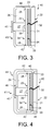
- Fig. 4 shows a cross-sectional view of the camera 40 and a camera carrier 44, as an example.
- the fixing means 33 may be at least one indentation or groove the surface of the housing 41 facing away form the interior space 26 may be provided with. Then the at least one indentation or groove can act together with appropriate counter fixing means 45 of the camera carrier 44.
- the counter fixing means 45 are preferably detents in order to form a snap-on connection with the at least one indentation or groove of the housing 41.
- the camera carrier 44 may designed to envelope or cover the housing 41.
- the camera carrier 44 may comprise a hole 46 matching the convex-shaped portion 43 of the housing 41 in order to allow the image sensor 35 to take pictures through this portion 43 of the housing 41 and the hole 46 of the camera carrier 44.
Landscapes
- Engineering & Computer Science (AREA)
- Multimedia (AREA)
- Signal Processing (AREA)
- Physics & Mathematics (AREA)
- Mechanical Engineering (AREA)
- Combustion & Propulsion (AREA)
- Chemical & Material Sciences (AREA)
- Thermal Sciences (AREA)
- General Engineering & Computer Science (AREA)
- General Physics & Mathematics (AREA)
- Studio Devices (AREA)
- Cold Air Circulating Systems And Constructional Details In Refrigerators (AREA)
- Accessories Of Cameras (AREA)
Abstract
Description
- The invention relates to a camera and to a domestic refrigerator which comprises such a camera.
- Published Japanese application for patent No.
200307258 - The object of the invention is to provide an improved camera for a domestic refrigerator.
- The object of the invention is achieved by means of camera for a domestic refrigerator, comprising a hood- or cup-shaped housing having an open end, a carrier which comprises a first surface and a second surface and is fixed to the housing in order to close the open end, the housing and the carrier enclosing an interior space and the first surface of the carrier facing towards the interior space, and an image sensor located inside the interior space and attached to the first surface of the carrier, at least a portion of the housing opposite to the image sensor being at least semi-transparent allowing the image sensor to take pictures through this portion of the housing, and the second surface of the carrier being casted in order to seal off the housing.
- A further aspect of the invention is a domestic refrigerator which comprises at least one camera according to the invention. The domestic refrigerator comprises a thermally insulated housing, a storage compartment intended for storing food and/or beverages and contained within the housing, a door leaf for closing and opening the storage compartment, and a cooling device for cooling the storage compartment. The storage compartment is intended to store food and/or beverages.
- The cooling device may in particular may be a refrigerant cycle generally known in the art. The domestic refrigerator may also comprise an electronic control device controlling the cooling device such that the storage compartment has a temperature which at least approximately equals a set-temperature.
- The storage compartment may be a fresh food compartment or a freezer compartment. The domestic refrigerator may also comprise more than one storage compartment.
- The domestic refrigerator may comprise a door leaf for opening and closing the storage compartment. The door leaf is, for instance, pivotally hinged with respect to the housing in particular with respect to a vertical axis.
- The camera is, for instance, attached to a surface of the housing facing towards the storage compartment. The camera may attached to a surface of the door leaf facing towards the storage compartment.
- Another aspect of the invention is a method for manufacturing the camera according to the invention, comprising the step of:
- fixing the carrier including the image sensor attached to the first surface of the carrier to the housing in particular at a predefined position in order to close the opening of the housing, and
- casting the second surface of the carrier in order to seal off the housing.
- The camera comprises the housing and the carrier. The carrier may be a printed circuit board and closes the open end of the hood- or cup-shaped housing to enclose the interior space. The image sensor is attached to the carrier and is placed within the interior space. The camera may comprise an optical lens in front of the image sensor. The optical lens is placed inside the interior space. The optical sensor may be a part of the image sensor.
- The portion opposite to image sensor is at least semi-transparent, preferably transparent in order to allow the image sensor to take pictures through the housing, i.e. through the at least semi-transparent portion of the housing.
- The second surface is casted utilizing, for instance, a pottant, resign or casting compound to seal off the housing and thus the interior space. Particularly, the pottant, resign or casting compound may seal off a potential gap between the housing and the carrier. More specifically, the pottant, resign or casting compound may seal off a potential gap between the carrier and the surface of the housing the carrier is touching.
- For an improved sealing, the pottant, resign or casting compound may be spread over the entire second surface of the carrier.
- Preferably, the carrier may be fixed to the housing at a predefined position.
- For instance for an easier manufacturing of the camera, the carrier may be slightly clamped to the housing at the predefined position.
- The housing may comprise first fixing means adapted to fix the carrier to the housing at the predefined position. The first fixing means may particularly comprise detents, allowing the camera to be assembled more easily and, thus, potentially faster.
- The housing of the camera may comprise a main body, which comprises a hole opposite to the image sensor, and a window as the at least semi-transparent portion of the housing. The window is inserted into the hole of the housing allowing the image sensor to take pictures through the window. The main body of the housing may preferably be opaque. The window, which may be made from plastics, is at least semi-transparent, preferably transparent. Preferably, the window is inserted and fixed into the hole of the main body such that the interior space is also sealed off at this part of the housing.
- Preferably, the housing of the camera is a one-piece housing. The one-piece housing may be entirely at least semi-transparent or transparent. Alternatively, the one-piece housing may be mostly opaque and at least semi-transparent, preferably transparent at the portion opposite to the image sensor.
- The shape of the portion of the housing opposite to the image sensor may be adapted to the shape of the optical lens. In particular, the portion of the housing opposite to the image sensor may be convex-shaped. This embodiment may be beneficial if the housing is covered with a camera carrier which comprises a hole matching the shape of the portion of the housing opposite to the image sensor in order to allow the image sensor to take pictures through this portion of the housing and the hole of the camera carrier. The camera carrier may be opaque.
- The housing may comprise second fixing means adapted to fix the housing to a camera carrier. The second fixing means may comprise at least one indentation or groove adapted to act together with appropriate counter fixing means of the camera carrier in order to form a snap-on connection.
- The camera may comprise an electric cable connected to the image sensor. The electric cable runs from the image sensor or from the carrier to the outside of the camera. Preferably, the electric cable is also casted, for instance, by the pottant, resign or casting compound.
- The camera according to the invention may particularly provide a capsulated camera or a capsulated compact camera module.
- Camera is intended to be placed inside a domestic refrigerator. A freezer in this context is also a refrigerator. Due to the sealing, the image sensor is protected against adverse environmental conditions inside the storage compartment of the refrigerator due to, for instance, acid fog caused by vegetables and fruits stored in the domestic refrigerator.
- The camera may be a camera module and comprises, for instance, the at least partial or semi-transparent housing which may be sealed by a pottant, resign or casting compound at its rear side.
- The invention will be described in greater detail hereafter, by way of non-limiting examples, with reference to the embodiments shown in the drawings, wherein
- Fig. 1
- is a perspective view of a domestic refrigerator,
- Fig. 2
- is a cross-sectional view of a first embodiment of a camera,
- Fig. 3
- is a cross-sectional view of a second embodiment of a camera, and
- Fig. 4
- is a cross-sectional view of the second embodiment of the camera including a camera carrier.
-
Fig.1 shows a perspective view of a domestic refrigerator 1. The domestic refrigerator 1 comprises a thermally insulatedhousing 2. Disposed within thehousing 2 is astorage compartment 3 intended for storing foods and/or beverages. - The domestic refrigerator 1 further comprises a thermally insulated
door leaf 4 for opening and closing thestorage compartment 3. Thedoor leaf 4 is pivotally hinged to thehousing 2 in particular with respect to a vertical axis and in particular by means of hinges. When thedoor leaf 4 is open, as shown inFig. 1 , then thestorage compartment 3 is accessible. - The domestic refrigerator 1 may comprise
several door shelves 6 arranged on the surface of thedoor leaf 5 facing towards thestorage compartment 3. - The domestic refrigerator 1 may comprise, as it is shown in
Fig. 1 ,several shelves 6 disposed on top of each other within thestorage compartment 3 and adrawer 7 disposed within and at the bottom of thestorage compartment 3. - The domestic refrigerator 1 further comprises a cooling device, particularly a refrigerant cycle for cooling the
storage compartment 3. In particular, the refrigerant cycle comprises, as it is generally known in the art, at least one compressor, at least one condenser, at least one expansion device and at least one evaporator. - The domestic refrigerator 1 comprises an electronic control device 8 which is configured to control the refrigeration cycle as it is generally known in the art. The electronic control device 8 may comprise a microcontroller or a microprocessor and controls the refrigeration cycle, in particular its compressor such that the actual temperatures of the
storage compartment 3 corresponds to a set value temperature. In order to control, in particular to feedback control the compressor, the domestic refrigerator 1 may comprise at least one temperature sensor not explicitly shown in the figures, coupled to the electronic control device 8 and configured to measure the actual temperature of thestorage compartment 3. - The domestic refrigerator 1 comprises at least one
camera storage compartment 3. Thecamera housing 2 facing towards thestorage compartment 3 or to the surface of thedoor leaf 4 facing towards thestorage compartment 3. -
Fig. 2 shows a cross-sectional view of a first embodiment of such acamera 20 andFig. 3 shows a cross-sectional view of a second embodiment of such acamera 40. If not explicitly mentioned thereafter, then equivalent components of thecameras Figures 2 and3 are denoted by the same reference signs. - The
camera 20 ofFig. 2 comprises ahousing 21 which is hood- or cup-shaped. Thehousing 21 comprises anopen end 22. - The
camera 20 comprises acarrier 34 which may, for instance, be a printed circuit board. Thecarrier 34 comprises afirst surface 23 and asecond surface 24 and is attached to thehousing 21 in order to close theopen end 22. Thecarrier 34 is preferably attached to the housing at a predefined position and may be slightly clamped to thehousing 21 at thepredefined position 25. Thehousing 21 and thecarrier 34 enclose aninterior space 26. Thefirst surface 23 of thecarrier 34 faces towards theinterior space 26 and thesecond surface 24 of thecarrier 34 faces away from theinterior space 26. - The
camera 20 comprises animage sensor 35, which is attached to thefirst surface 23 of thecarrier 34 and, thus, is located within theinterior space 26. Thecamera 20 may further comprise anoptical lens 27 which is placed in front of theimage sensor 35 within theinterior space 26. Theoptical lens 27 may be attached to thefirst surface 23 of thecarrier 34. Theoptical lens 27 may be a part of theimage sensor 35. - For the example embodiment shown, the
housing 21 may comprise amain body 28 which comprises ahole 29 opposite to itsopen end 22 and opposite to theimage sensor 35. Themain body 28 may be opaque. Themain body 28 may be made from plastics. - The
housing 21 may comprise awindow 30 which is inserted into thehole 29. Thewindow 30 is transparent, at least semi-transparent in order to allow theimage sensor 35 to take pictures through thewindow 30. Thewindow 30 may be made from plastics. - The
second surface 24 of thecarrier 35 is casted in particular by means of apottant 31, resign or casting compound in order to seal off thehousing 21. Particularly, the pottant 31 seals off a potential gap between thehousing 21 and thecarrier 35. More specifically, thepottant 31 may seal off a potential gap between thecarrier 34 and the surface of thehousing 21 thecarrier 34 is touching. Preferably, thepottant 31 is spread over the entiresecond surface 24 of thecarrier 34. - The
camera 20 may comprise anelectric cable 32 for an electric connection of theimage sensor 35. Theelectric cable 32 may run through thepottant 31. - The
housing 21 may further comprise fixing means 33 intended to fasten thecamera 20 to a camera carrier not explicitly shown inFig. 2 . The fixing means 33 may be at least one indentation or groove the surface of thehousing 21 facing away form theinterior space 26 may be provided with. Then the at least one indentation or groove can act together with appropriate counter fixing means of the camera carrier in order to form, for instance, a snap-on connection. -
Fig. 3 shows the cross-section of the second embodiment of thecamera 40. - Essentially, the two
cameras housings housing 41 of thecamera 40 shown inFig. 3 may comprisedetents 42 at thepredefined position 25 for improved fixing thecarrier 34 to thehousing 41 at thepredefined position 25. Thedetents 42 may protrude from the surface of thehousing 41 facing towards theinterior space 26. Thecarrier 34 may also be slightly clamped to thehousing 41 at thepredefined position 25. Thehousing 21 of thecamera 20 ofFig. 2 may also comprise thedetents 42. - Contrary to the
housing 21 of thecamera 20 depicted inFig. 2 , thehousing 41 of thecamera 40 shown inFig. 3 is made as a one-piece housing 41 which is hood- or cup-shaped. Thehousing 41 may be made from plastics. - The
housing 41 comprises aportion 43 which is located opposite to theopen end 22 and opposite to theimage lens 35. At least thisportion 43 is transparent, at least semi-transparent in order to allow theimage sensor 35 to take pictures through thisportion 43 of thehousing 41. Preferably, theentire housing 41 is transparent, at least semi-transparent. - For the example second embodiment, the shape of the
portion 43 of thehousing 41 located opposite to theopen end 22 and theimage sensor 35 may be adapted to the shape of theoptical lens 27. In particular, thisportion 43 of thehousing 41 may be convex-shaped. - The
housing 41 may also comprise the fixing means 33 intended to fasten thecamera 40 to a camera carrier.Fig. 4 shows a cross-sectional view of thecamera 40 and acamera carrier 44, as an example. - The fixing means 33 may be at least one indentation or groove the surface of the
housing 41 facing away form theinterior space 26 may be provided with. Then the at least one indentation or groove can act together with appropriate counter fixing means 45 of thecamera carrier 44. The counter fixing means 45 are preferably detents in order to form a snap-on connection with the at least one indentation or groove of thehousing 41. - The
camera carrier 44 may designed to envelope or cover thehousing 41. Thecamera carrier 44 may comprise ahole 46 matching the convex-shapedportion 43 of thehousing 41 in order to allow theimage sensor 35 to take pictures through thisportion 43 of thehousing 41 and thehole 46 of thecamera carrier 44. -
- 1
- domestic refrigerator
- 2
- housing
- 3
- storage compartment
- 4
- door leaf
- 5
- door shelves
- 6
- shelves
- 7
- drawer
- 8
- electronic control device
- 20
- camera
- 21
- housing
- 22
- open end
- 23
- first surface
- 24
- second surface
- 25
- position
- 26
- interior space
- 27
- optical lens
- 28
- main body
- 29
- hole
- 30
- window
- 31
- pottant
- 32
- electric cable
- 33
- fixing means
- 34
- carrier
- 35
- image sensor
- 40
- camera
- 41
- housing
- 42
- detents
- 43
- portion
- 44
- camera carrier
- 45
- detents
- 46
- hole
Claims (10)
- Camera for a domestic refrigerator (1), comprising- a hood- or cup-shaped housing (21, 41) having an open end (22),- a carrier (34) which comprises a first surface (23) and a second surface (24) and is fixed to the housing (21, 41) in order to close the open end (22), the housing (21, 41) and the carrier (34) enclosing an interior space (26) and the first surface (23) of the carrier (34) facing towards the interior space (26), and- an image sensor (35) located inside the interior space (26) and attached to the first surface (23) of the carrier (34), at least a portion (30, 43) of the housing (21, 41) opposite to the image sensor (21, 41) being at least semi-transparent allowing the image sensor (35) to take pictures through this portion (30, 43) of the housing (21, 41), and the second surface (24) of the carrier (34) being casted in order to seal off the housing (21, 41).
- The camera of claim 1, wherein the second surface (24) of the carrier (34) is casted by means of a pottant (31) which in particular is spread over the entire second surface (24) of the carrier (34).
- The camera of claim 1 or 2, wherein the carrier (34) is slightly clamped to the housing (21, 41) at a predefined position (25), and/or comprises first fixing means adapted to fix the carrier (34) to the housing (41) at the predefined position (25), the first fixing means particularly comprising detents (42).
- The camera of any of claims 1-3, wherein the housing (41) is a one-piece housing (41), which in particular is entirely at least semi-transparent.
- The camera of claim 4, wherein the portion (43) of the housing (41) opposite to the image sensor (35) is convex-shaped, and/or wherein the camera (40) comprises an optical lens (27) placed in front of the image sensor (35) within the interior space (26) or being a part of the image sensor (35), the shape of the portion (43) of the housing (41) opposite to the image sensor (35) being adapted to the shape of the optical lens (27).
- The camera of any of claims 1-3, wherein the housing (21) comprises a main body (28), which comprises a hole (29) opposite to the image sensor (35), and a window (30) as the at least semi-transparent portion of the housing (21), the window (30) being inserted into the hole (29) of the housing (21) allowing the image sensor (35) to take pictures through the window (30).
- The camera of any of claims 1-6, wherein the housing (21, 41) comprises second fixing means (33) adapted to fix the housing (21, 41) to a camera carrier (44), in particular the second fixing means (33) comprising at least one indentation or groove adapted to act together with appropriate counter fixing means (45) of the camera carrier (44) in order to form a snap-on connection.
- The camera of claim 7, wherein the camera carrier (44) covers the housing (41) and comprises a hole (46) matching the shape of the portion (43) of the housing (41) opposite to the image sensor (35) in order to allow the image sensor (35) to take pictures through this portion (43) of the housing (41) and the hole (46) of the camera carrier (44).
- Domestic refrigerator, comprising a thermally insulated housing (2), a storage compartment (3) intended for storing food and/or beverages and contained within the housing (2), and a cooling device configured to cool the storage compartment (3), characterized by a camera (20) according to any of claims 1-9, the camera (20, 40) being adapted to take at least one picture from the interior of the storage compartment (3).
- Method for manufacturing a camera (20, 40) according to any of the claims 1-8, comprising the step of:- fixing the carrier (34) including the image sensor (35) attached to the first surface (23) of the carrier (34) to the housing (21, 41) in particular at a predefined position (25) in order to close the opening (22) of the housing (21, 41), and- casting the second surface (24) of the carrier (34) in order to seal off the housing (21,41).
Priority Applications (3)
| Application Number | Priority Date | Filing Date | Title |
|---|---|---|---|
| PL15156054T PL3059535T3 (en) | 2015-02-23 | 2015-02-23 | Domestic refrigerator comprising a camera |
| EP15156054.7A EP3059535B1 (en) | 2015-02-23 | 2015-02-23 | Domestic refrigerator comprising a camera |
| CN201610091459.6A CN105915768B (en) | 2015-02-23 | 2016-02-18 | Camera device and household refrigeration appliance comprising same |
Applications Claiming Priority (1)
| Application Number | Priority Date | Filing Date | Title |
|---|---|---|---|
| EP15156054.7A EP3059535B1 (en) | 2015-02-23 | 2015-02-23 | Domestic refrigerator comprising a camera |
Publications (2)
| Publication Number | Publication Date |
|---|---|
| EP3059535A1 true EP3059535A1 (en) | 2016-08-24 |
| EP3059535B1 EP3059535B1 (en) | 2019-09-04 |
Family
ID=52544367
Family Applications (1)
| Application Number | Title | Priority Date | Filing Date |
|---|---|---|---|
| EP15156054.7A Active EP3059535B1 (en) | 2015-02-23 | 2015-02-23 | Domestic refrigerator comprising a camera |
Country Status (3)
| Country | Link |
|---|---|
| EP (1) | EP3059535B1 (en) |
| CN (1) | CN105915768B (en) |
| PL (1) | PL3059535T3 (en) |
Cited By (4)
| Publication number | Priority date | Publication date | Assignee | Title |
|---|---|---|---|---|
| US20160370107A1 (en) * | 2015-06-16 | 2016-12-22 | Dongbu Daewoo Electronics Corporation | Refrigerator providing local cooling |
| WO2018205558A1 (en) * | 2017-05-08 | 2018-11-15 | 合肥美的智能科技有限公司 | Refrigerator and control method therefor |
| US11419434B1 (en) * | 2018-10-03 | 2022-08-23 | Anthony, Inc. | Display case door with door handle camera |
| US11650628B1 (en) | 2018-10-03 | 2023-05-16 | Anthony, Inc. | Display case door with touch screen |
Families Citing this family (3)
| Publication number | Priority date | Publication date | Assignee | Title |
|---|---|---|---|---|
| DE102017216960A1 (en) * | 2017-09-25 | 2019-03-28 | BSH Hausgeräte GmbH | Household refrigerator with a digital camera |
| DE102017216959A1 (en) * | 2017-09-25 | 2019-03-28 | BSH Hausgeräte GmbH | Digital camera and household refrigerator with a digital camera |
| CN120027568A (en) * | 2023-11-21 | 2025-05-23 | 博西华电器(江苏)有限公司 | Household appliances including cameras and installation methods |
Citations (3)
| Publication number | Priority date | Publication date | Assignee | Title |
|---|---|---|---|---|
| JP2003007258A (en) | 2001-06-25 | 2003-01-10 | Shin Kobe Electric Mach Co Ltd | Lead storage battery |
| WO2014142118A1 (en) * | 2013-03-12 | 2014-09-18 | 株式会社 東芝 | Refrigerator, camera device, refrigerator door pocket, and refrigerator holder |
| WO2014142119A1 (en) * | 2013-03-12 | 2014-09-18 | 株式会社 東芝 | Refrigerator and camera device |
Family Cites Families (8)
| Publication number | Priority date | Publication date | Assignee | Title |
|---|---|---|---|---|
| US4322954A (en) * | 1979-05-23 | 1982-04-06 | Sheehan Laurence M | Portable cooler for medicine |
| JP2009017245A (en) * | 2007-07-05 | 2009-01-22 | Hitachi Ltd | Dome camera |
| DE102008054417A1 (en) * | 2008-12-09 | 2010-06-10 | BSH Bosch und Siemens Hausgeräte GmbH | Refrigerating appliance, in particular household freezer |
| KR101270144B1 (en) * | 2012-11-05 | 2013-05-31 | 일성미디어통신 주식회사 | Waterproof surveillance camera |
| KR102000448B1 (en) * | 2013-03-27 | 2019-10-01 | 엘지전자 주식회사 | Refrigerator |
| CN103499184A (en) * | 2013-09-04 | 2014-01-08 | 周薇 | Refrigerator monitored by mobile phone |
| CN203965900U (en) * | 2014-05-13 | 2014-11-26 | 蒋雪峰 | Refrigerator intelligent monitor system based on Internet of Things |
| CN203908183U (en) * | 2014-06-25 | 2014-10-29 | 宁波梵科电子科技有限公司 | Refrigerator with camera shooting function |
-
2015
- 2015-02-23 EP EP15156054.7A patent/EP3059535B1/en active Active
- 2015-02-23 PL PL15156054T patent/PL3059535T3/en unknown
-
2016
- 2016-02-18 CN CN201610091459.6A patent/CN105915768B/en active Active
Patent Citations (3)
| Publication number | Priority date | Publication date | Assignee | Title |
|---|---|---|---|---|
| JP2003007258A (en) | 2001-06-25 | 2003-01-10 | Shin Kobe Electric Mach Co Ltd | Lead storage battery |
| WO2014142118A1 (en) * | 2013-03-12 | 2014-09-18 | 株式会社 東芝 | Refrigerator, camera device, refrigerator door pocket, and refrigerator holder |
| WO2014142119A1 (en) * | 2013-03-12 | 2014-09-18 | 株式会社 東芝 | Refrigerator and camera device |
Cited By (4)
| Publication number | Priority date | Publication date | Assignee | Title |
|---|---|---|---|---|
| US20160370107A1 (en) * | 2015-06-16 | 2016-12-22 | Dongbu Daewoo Electronics Corporation | Refrigerator providing local cooling |
| WO2018205558A1 (en) * | 2017-05-08 | 2018-11-15 | 合肥美的智能科技有限公司 | Refrigerator and control method therefor |
| US11419434B1 (en) * | 2018-10-03 | 2022-08-23 | Anthony, Inc. | Display case door with door handle camera |
| US11650628B1 (en) | 2018-10-03 | 2023-05-16 | Anthony, Inc. | Display case door with touch screen |
Also Published As
| Publication number | Publication date |
|---|---|
| CN105915768B (en) | 2020-01-10 |
| EP3059535B1 (en) | 2019-09-04 |
| CN105915768A (en) | 2016-08-31 |
| PL3059535T3 (en) | 2020-04-30 |
Similar Documents
| Publication | Publication Date | Title |
|---|---|---|
| EP3059535B1 (en) | Domestic refrigerator comprising a camera | |
| US10951863B2 (en) | Refrigerator, camera device, refrigerator door pocket, and home appliance network system | |
| EP3336464B1 (en) | Refrigerator | |
| EP3244147B1 (en) | Refrigerator | |
| RU2711583C1 (en) | Two-door refrigerator with image production device | |
| KR20140047360A (en) | Refrigerator for preventing coagulation of door gasket | |
| US20170131024A1 (en) | Domestic Refrigeration Appliance Having An Interior Lighting Arrangement | |
| WO2015029824A1 (en) | Camera device for refrigerator and refrigerator comprising same | |
| US20190170429A1 (en) | Refrigerator | |
| WO2021212993A1 (en) | Camera module in refrigeration appliance and method for preventing lens from fogging | |
| WO2010118938A3 (en) | Refrigeration device having a non-fogging window | |
| US20160320119A1 (en) | Household refrigerator | |
| AU2016389530A1 (en) | Refrigerator | |
| KR20150045256A (en) | Refrigerator | |
| JP6795997B2 (en) | refrigerator | |
| US20160305704A1 (en) | Domestic refrigeration appliance with a specific machinery-chamber boundary wall | |
| US11703272B2 (en) | Drawer-shelf system for a refrigerator appliance | |
| US20200284504A1 (en) | Domestic refrigeration appliance comprising a digital camera | |
| CN110017656A (en) | Domestic refrigerator with lighting device | |
| CN109974380A (en) | Refrigerator | |
| US9989303B1 (en) | Refrigeration device comprising a transport securing element | |
| US20260104192A1 (en) | Refrigeration device, method for assembling a refrigeration device | |
| US20100254116A1 (en) | Lighting apparatus and refrigerator having the same | |
| CN111981752A (en) | Refrigerator with a door | |
| CN220017799U (en) | Refrigerator |
Legal Events
| Date | Code | Title | Description |
|---|---|---|---|
| PUAI | Public reference made under article 153(3) epc to a published international application that has entered the european phase |
Free format text: ORIGINAL CODE: 0009012 |
|
| AK | Designated contracting states |
Kind code of ref document: A1 Designated state(s): AL AT BE BG CH CY CZ DE DK EE ES FI FR GB GR HR HU IE IS IT LI LT LU LV MC MK MT NL NO PL PT RO RS SE SI SK SM TR |
|
| AX | Request for extension of the european patent |
Extension state: BA ME |
|
| STAA | Information on the status of an ep patent application or granted ep patent |
Free format text: STATUS: REQUEST FOR EXAMINATION WAS MADE |
|
| 17P | Request for examination filed |
Effective date: 20170224 |
|
| RBV | Designated contracting states (corrected) |
Designated state(s): AL AT BE BG CH CY CZ DE DK EE ES FI FR GB GR HR HU IE IS IT LI LT LU LV MC MK MT NL NO PL PT RO RS SE SI SK SM TR |
|
| STAA | Information on the status of an ep patent application or granted ep patent |
Free format text: STATUS: EXAMINATION IS IN PROGRESS |
|
| 17Q | First examination report despatched |
Effective date: 20190220 |
|
| GRAP | Despatch of communication of intention to grant a patent |
Free format text: ORIGINAL CODE: EPIDOSNIGR1 |
|
| STAA | Information on the status of an ep patent application or granted ep patent |
Free format text: STATUS: GRANT OF PATENT IS INTENDED |
|
| INTG | Intention to grant announced |
Effective date: 20190416 |
|
| RIN1 | Information on inventor provided before grant (corrected) |
Inventor name: WETZL, GERHARD Inventor name: WERNER, HANS PETER |
|
| GRAS | Grant fee paid |
Free format text: ORIGINAL CODE: EPIDOSNIGR3 |
|
| GRAA | (expected) grant |
Free format text: ORIGINAL CODE: 0009210 |
|
| STAA | Information on the status of an ep patent application or granted ep patent |
Free format text: STATUS: THE PATENT HAS BEEN GRANTED |
|
| AK | Designated contracting states |
Kind code of ref document: B1 Designated state(s): AL AT BE BG CH CY CZ DE DK EE ES FI FR GB GR HR HU IE IS IT LI LT LU LV MC MK MT NL NO PL PT RO RS SE SI SK SM TR |
|
| REG | Reference to a national code |
Ref country code: GB Ref legal event code: FG4D |
|
| REG | Reference to a national code |
Ref country code: CH Ref legal event code: EP |
|
| REG | Reference to a national code |
Ref country code: AT Ref legal event code: REF Ref document number: 1175952 Country of ref document: AT Kind code of ref document: T Effective date: 20190915 |
|
| REG | Reference to a national code |
Ref country code: DE Ref legal event code: R096 Ref document number: 602015037012 Country of ref document: DE |
|
| REG | Reference to a national code |
Ref country code: IE Ref legal event code: FG4D |
|
| REG | Reference to a national code |
Ref country code: NL Ref legal event code: MP Effective date: 20190904 |
|
| REG | Reference to a national code |
Ref country code: LT Ref legal event code: MG4D |
|
| PG25 | Lapsed in a contracting state [announced via postgrant information from national office to epo] |
Ref country code: NO Free format text: LAPSE BECAUSE OF FAILURE TO SUBMIT A TRANSLATION OF THE DESCRIPTION OR TO PAY THE FEE WITHIN THE PRESCRIBED TIME-LIMIT Effective date: 20191204 Ref country code: HR Free format text: LAPSE BECAUSE OF FAILURE TO SUBMIT A TRANSLATION OF THE DESCRIPTION OR TO PAY THE FEE WITHIN THE PRESCRIBED TIME-LIMIT Effective date: 20190904 Ref country code: SE Free format text: LAPSE BECAUSE OF FAILURE TO SUBMIT A TRANSLATION OF THE DESCRIPTION OR TO PAY THE FEE WITHIN THE PRESCRIBED TIME-LIMIT Effective date: 20190904 Ref country code: FI Free format text: LAPSE BECAUSE OF FAILURE TO SUBMIT A TRANSLATION OF THE DESCRIPTION OR TO PAY THE FEE WITHIN THE PRESCRIBED TIME-LIMIT Effective date: 20190904 Ref country code: LT Free format text: LAPSE BECAUSE OF FAILURE TO SUBMIT A TRANSLATION OF THE DESCRIPTION OR TO PAY THE FEE WITHIN THE PRESCRIBED TIME-LIMIT Effective date: 20190904 Ref country code: BG Free format text: LAPSE BECAUSE OF FAILURE TO SUBMIT A TRANSLATION OF THE DESCRIPTION OR TO PAY THE FEE WITHIN THE PRESCRIBED TIME-LIMIT Effective date: 20191204 |
|
| PG25 | Lapsed in a contracting state [announced via postgrant information from national office to epo] |
Ref country code: ES Free format text: LAPSE BECAUSE OF FAILURE TO SUBMIT A TRANSLATION OF THE DESCRIPTION OR TO PAY THE FEE WITHIN THE PRESCRIBED TIME-LIMIT Effective date: 20190904 Ref country code: AL Free format text: LAPSE BECAUSE OF FAILURE TO SUBMIT A TRANSLATION OF THE DESCRIPTION OR TO PAY THE FEE WITHIN THE PRESCRIBED TIME-LIMIT Effective date: 20190904 Ref country code: GR Free format text: LAPSE BECAUSE OF FAILURE TO SUBMIT A TRANSLATION OF THE DESCRIPTION OR TO PAY THE FEE WITHIN THE PRESCRIBED TIME-LIMIT Effective date: 20191205 Ref country code: LV Free format text: LAPSE BECAUSE OF FAILURE TO SUBMIT A TRANSLATION OF THE DESCRIPTION OR TO PAY THE FEE WITHIN THE PRESCRIBED TIME-LIMIT Effective date: 20190904 Ref country code: RS Free format text: LAPSE BECAUSE OF FAILURE TO SUBMIT A TRANSLATION OF THE DESCRIPTION OR TO PAY THE FEE WITHIN THE PRESCRIBED TIME-LIMIT Effective date: 20190904 |
|
| REG | Reference to a national code |
Ref country code: AT Ref legal event code: MK05 Ref document number: 1175952 Country of ref document: AT Kind code of ref document: T Effective date: 20190904 |
|
| PG25 | Lapsed in a contracting state [announced via postgrant information from national office to epo] |
Ref country code: PT Free format text: LAPSE BECAUSE OF FAILURE TO SUBMIT A TRANSLATION OF THE DESCRIPTION OR TO PAY THE FEE WITHIN THE PRESCRIBED TIME-LIMIT Effective date: 20200106 Ref country code: RO Free format text: LAPSE BECAUSE OF FAILURE TO SUBMIT A TRANSLATION OF THE DESCRIPTION OR TO PAY THE FEE WITHIN THE PRESCRIBED TIME-LIMIT Effective date: 20190904 Ref country code: EE Free format text: LAPSE BECAUSE OF FAILURE TO SUBMIT A TRANSLATION OF THE DESCRIPTION OR TO PAY THE FEE WITHIN THE PRESCRIBED TIME-LIMIT Effective date: 20190904 Ref country code: NL Free format text: LAPSE BECAUSE OF FAILURE TO SUBMIT A TRANSLATION OF THE DESCRIPTION OR TO PAY THE FEE WITHIN THE PRESCRIBED TIME-LIMIT Effective date: 20190904 Ref country code: AT Free format text: LAPSE BECAUSE OF FAILURE TO SUBMIT A TRANSLATION OF THE DESCRIPTION OR TO PAY THE FEE WITHIN THE PRESCRIBED TIME-LIMIT Effective date: 20190904 |
|
| PG25 | Lapsed in a contracting state [announced via postgrant information from national office to epo] |
Ref country code: IS Free format text: LAPSE BECAUSE OF FAILURE TO SUBMIT A TRANSLATION OF THE DESCRIPTION OR TO PAY THE FEE WITHIN THE PRESCRIBED TIME-LIMIT Effective date: 20200224 Ref country code: SM Free format text: LAPSE BECAUSE OF FAILURE TO SUBMIT A TRANSLATION OF THE DESCRIPTION OR TO PAY THE FEE WITHIN THE PRESCRIBED TIME-LIMIT Effective date: 20190904 Ref country code: SK Free format text: LAPSE BECAUSE OF FAILURE TO SUBMIT A TRANSLATION OF THE DESCRIPTION OR TO PAY THE FEE WITHIN THE PRESCRIBED TIME-LIMIT Effective date: 20190904 Ref country code: CZ Free format text: LAPSE BECAUSE OF FAILURE TO SUBMIT A TRANSLATION OF THE DESCRIPTION OR TO PAY THE FEE WITHIN THE PRESCRIBED TIME-LIMIT Effective date: 20190904 |
|
| REG | Reference to a national code |
Ref country code: DE Ref legal event code: R097 Ref document number: 602015037012 Country of ref document: DE |
|
| PLBE | No opposition filed within time limit |
Free format text: ORIGINAL CODE: 0009261 |
|
| STAA | Information on the status of an ep patent application or granted ep patent |
Free format text: STATUS: NO OPPOSITION FILED WITHIN TIME LIMIT |
|
| PG2D | Information on lapse in contracting state deleted |
Ref country code: IS |
|
| PG25 | Lapsed in a contracting state [announced via postgrant information from national office to epo] |
Ref country code: DK Free format text: LAPSE BECAUSE OF FAILURE TO SUBMIT A TRANSLATION OF THE DESCRIPTION OR TO PAY THE FEE WITHIN THE PRESCRIBED TIME-LIMIT Effective date: 20190904 Ref country code: IS Free format text: LAPSE BECAUSE OF FAILURE TO SUBMIT A TRANSLATION OF THE DESCRIPTION OR TO PAY THE FEE WITHIN THE PRESCRIBED TIME-LIMIT Effective date: 20200105 |
|
| 26N | No opposition filed |
Effective date: 20200605 |
|
| PG25 | Lapsed in a contracting state [announced via postgrant information from national office to epo] |
Ref country code: SI Free format text: LAPSE BECAUSE OF FAILURE TO SUBMIT A TRANSLATION OF THE DESCRIPTION OR TO PAY THE FEE WITHIN THE PRESCRIBED TIME-LIMIT Effective date: 20190904 |
|
| REG | Reference to a national code |
Ref country code: CH Ref legal event code: PL |
|
| GBPC | Gb: european patent ceased through non-payment of renewal fee |
Effective date: 20200223 |
|
| REG | Reference to a national code |
Ref country code: BE Ref legal event code: MM Effective date: 20200229 |
|
| PG25 | Lapsed in a contracting state [announced via postgrant information from national office to epo] |
Ref country code: LU Free format text: LAPSE BECAUSE OF NON-PAYMENT OF DUE FEES Effective date: 20200223 Ref country code: MC Free format text: LAPSE BECAUSE OF FAILURE TO SUBMIT A TRANSLATION OF THE DESCRIPTION OR TO PAY THE FEE WITHIN THE PRESCRIBED TIME-LIMIT Effective date: 20190904 |
|
| PG25 | Lapsed in a contracting state [announced via postgrant information from national office to epo] |
Ref country code: CH Free format text: LAPSE BECAUSE OF NON-PAYMENT OF DUE FEES Effective date: 20200229 Ref country code: LI Free format text: LAPSE BECAUSE OF NON-PAYMENT OF DUE FEES Effective date: 20200229 |
|
| PG25 | Lapsed in a contracting state [announced via postgrant information from national office to epo] |
Ref country code: FR Free format text: LAPSE BECAUSE OF NON-PAYMENT OF DUE FEES Effective date: 20200229 Ref country code: IE Free format text: LAPSE BECAUSE OF NON-PAYMENT OF DUE FEES Effective date: 20200223 Ref country code: GB Free format text: LAPSE BECAUSE OF NON-PAYMENT OF DUE FEES Effective date: 20200223 |
|
| PG25 | Lapsed in a contracting state [announced via postgrant information from national office to epo] |
Ref country code: BE Free format text: LAPSE BECAUSE OF NON-PAYMENT OF DUE FEES Effective date: 20200229 |
|
| PG25 | Lapsed in a contracting state [announced via postgrant information from national office to epo] |
Ref country code: MT Free format text: LAPSE BECAUSE OF FAILURE TO SUBMIT A TRANSLATION OF THE DESCRIPTION OR TO PAY THE FEE WITHIN THE PRESCRIBED TIME-LIMIT Effective date: 20190904 Ref country code: CY Free format text: LAPSE BECAUSE OF FAILURE TO SUBMIT A TRANSLATION OF THE DESCRIPTION OR TO PAY THE FEE WITHIN THE PRESCRIBED TIME-LIMIT Effective date: 20190904 |
|
| PG25 | Lapsed in a contracting state [announced via postgrant information from national office to epo] |
Ref country code: MK Free format text: LAPSE BECAUSE OF FAILURE TO SUBMIT A TRANSLATION OF THE DESCRIPTION OR TO PAY THE FEE WITHIN THE PRESCRIBED TIME-LIMIT Effective date: 20190904 |
|
| PGFP | Annual fee paid to national office [announced via postgrant information from national office to epo] |
Ref country code: TR Payment date: 20230222 Year of fee payment: 9 Ref country code: PL Payment date: 20230213 Year of fee payment: 9 Ref country code: IT Payment date: 20230228 Year of fee payment: 9 |
|
| PG25 | Lapsed in a contracting state [announced via postgrant information from national office to epo] |
Ref country code: IT Free format text: LAPSE BECAUSE OF NON-PAYMENT OF DUE FEES Effective date: 20240223 |
|
| PGFP | Annual fee paid to national office [announced via postgrant information from national office to epo] |
Ref country code: DE Payment date: 20240703 Year of fee payment: 11 |
|
| PG25 | Lapsed in a contracting state [announced via postgrant information from national office to epo] |
Ref country code: PL Free format text: LAPSE BECAUSE OF NON-PAYMENT OF DUE FEES Effective date: 20240223 |