EP3059454A1 - Impeller, rotary machine, and impeller manufacturing method - Google Patents
Impeller, rotary machine, and impeller manufacturing method Download PDFInfo
- Publication number
- EP3059454A1 EP3059454A1 EP14864299.4A EP14864299A EP3059454A1 EP 3059454 A1 EP3059454 A1 EP 3059454A1 EP 14864299 A EP14864299 A EP 14864299A EP 3059454 A1 EP3059454 A1 EP 3059454A1
- Authority
- EP
- European Patent Office
- Prior art keywords
- axis
- impeller
- section
- blade sections
- rotary shaft
- Prior art date
- Legal status (The legal status is an assumption and is not a legal conclusion. Google has not performed a legal analysis and makes no representation as to the accuracy of the status listed.)
- Granted
Links
- 238000004519 manufacturing process Methods 0.000 title claims description 12
- 238000000034 method Methods 0.000 claims description 13
- 238000005219 brazing Methods 0.000 claims description 12
- 238000003466 welding Methods 0.000 claims description 6
- 238000005304 joining Methods 0.000 claims description 5
- 238000003756 stirring Methods 0.000 claims description 3
- 239000000463 material Substances 0.000 description 4
- 230000013011 mating Effects 0.000 description 4
- 238000005520 cutting process Methods 0.000 description 3
- 238000012986 modification Methods 0.000 description 3
- 230000004048 modification Effects 0.000 description 3
- 238000006073 displacement reaction Methods 0.000 description 2
- 238000012423 maintenance Methods 0.000 description 2
- 230000001105 regulatory effect Effects 0.000 description 2
- 238000010008 shearing Methods 0.000 description 2
- 230000002411 adverse Effects 0.000 description 1
- 238000005266 casting Methods 0.000 description 1
- 230000000694 effects Effects 0.000 description 1
- 238000005516 engineering process Methods 0.000 description 1
- 239000012530 fluid Substances 0.000 description 1
- 238000010438 heat treatment Methods 0.000 description 1
- 238000003754 machining Methods 0.000 description 1
- 238000004881 precipitation hardening Methods 0.000 description 1
- 229910001220 stainless steel Inorganic materials 0.000 description 1
- 239000010935 stainless steel Substances 0.000 description 1
- 238000011144 upstream manufacturing Methods 0.000 description 1
Images


Classifications
-
- F—MECHANICAL ENGINEERING; LIGHTING; HEATING; WEAPONS; BLASTING
- F04—POSITIVE - DISPLACEMENT MACHINES FOR LIQUIDS; PUMPS FOR LIQUIDS OR ELASTIC FLUIDS
- F04D—NON-POSITIVE-DISPLACEMENT PUMPS
- F04D29/00—Details, component parts, or accessories
- F04D29/26—Rotors specially for elastic fluids
- F04D29/28—Rotors specially for elastic fluids for centrifugal or helico-centrifugal pumps for radial-flow or helico-centrifugal pumps
- F04D29/284—Rotors specially for elastic fluids for centrifugal or helico-centrifugal pumps for radial-flow or helico-centrifugal pumps for compressors
-
- F—MECHANICAL ENGINEERING; LIGHTING; HEATING; WEAPONS; BLASTING
- F04—POSITIVE - DISPLACEMENT MACHINES FOR LIQUIDS; PUMPS FOR LIQUIDS OR ELASTIC FLUIDS
- F04D—NON-POSITIVE-DISPLACEMENT PUMPS
- F04D17/00—Radial-flow pumps, e.g. centrifugal pumps; Helico-centrifugal pumps
- F04D17/08—Centrifugal pumps
- F04D17/10—Centrifugal pumps for compressing or evacuating
-
- F—MECHANICAL ENGINEERING; LIGHTING; HEATING; WEAPONS; BLASTING
- F04—POSITIVE - DISPLACEMENT MACHINES FOR LIQUIDS; PUMPS FOR LIQUIDS OR ELASTIC FLUIDS
- F04D—NON-POSITIVE-DISPLACEMENT PUMPS
- F04D17/00—Radial-flow pumps, e.g. centrifugal pumps; Helico-centrifugal pumps
- F04D17/08—Centrifugal pumps
- F04D17/10—Centrifugal pumps for compressing or evacuating
- F04D17/12—Multi-stage pumps
- F04D17/122—Multi-stage pumps the individual rotor discs being, one for each stage, on a common shaft and axially spaced, e.g. conventional centrifugal multi- stage compressors
-
- F—MECHANICAL ENGINEERING; LIGHTING; HEATING; WEAPONS; BLASTING
- F04—POSITIVE - DISPLACEMENT MACHINES FOR LIQUIDS; PUMPS FOR LIQUIDS OR ELASTIC FLUIDS
- F04D—NON-POSITIVE-DISPLACEMENT PUMPS
- F04D29/00—Details, component parts, or accessories
- F04D29/26—Rotors specially for elastic fluids
- F04D29/266—Rotors specially for elastic fluids mounting compressor rotors on shafts
-
- F—MECHANICAL ENGINEERING; LIGHTING; HEATING; WEAPONS; BLASTING
- F04—POSITIVE - DISPLACEMENT MACHINES FOR LIQUIDS; PUMPS FOR LIQUIDS OR ELASTIC FLUIDS
- F04D—NON-POSITIVE-DISPLACEMENT PUMPS
- F04D29/00—Details, component parts, or accessories
- F04D29/60—Mounting; Assembling; Disassembling
- F04D29/62—Mounting; Assembling; Disassembling of radial or helico-centrifugal pumps
- F04D29/624—Mounting; Assembling; Disassembling of radial or helico-centrifugal pumps especially adapted for elastic fluid pumps
-
- F—MECHANICAL ENGINEERING; LIGHTING; HEATING; WEAPONS; BLASTING
- F05—INDEXING SCHEMES RELATING TO ENGINES OR PUMPS IN VARIOUS SUBCLASSES OF CLASSES F01-F04
- F05D—INDEXING SCHEME FOR ASPECTS RELATING TO NON-POSITIVE-DISPLACEMENT MACHINES OR ENGINES, GAS-TURBINES OR JET-PROPULSION PLANTS
- F05D2230/00—Manufacture
- F05D2230/20—Manufacture essentially without removing material
- F05D2230/23—Manufacture essentially without removing material by permanently joining parts together
- F05D2230/232—Manufacture essentially without removing material by permanently joining parts together by welding
- F05D2230/237—Brazing
-
- F—MECHANICAL ENGINEERING; LIGHTING; HEATING; WEAPONS; BLASTING
- F05—INDEXING SCHEMES RELATING TO ENGINES OR PUMPS IN VARIOUS SUBCLASSES OF CLASSES F01-F04
- F05D—INDEXING SCHEME FOR ASPECTS RELATING TO NON-POSITIVE-DISPLACEMENT MACHINES OR ENGINES, GAS-TURBINES OR JET-PROPULSION PLANTS
- F05D2230/00—Manufacture
- F05D2230/20—Manufacture essentially without removing material
- F05D2230/23—Manufacture essentially without removing material by permanently joining parts together
- F05D2230/232—Manufacture essentially without removing material by permanently joining parts together by welding
- F05D2230/239—Inertia or friction welding
Definitions
- the present invention relates to an impeller, a rotary machine, and an impeller manufacturing method.
- Rotary machines used in, for instance, industrial compressors, turbo refrigerators, small gas turbines, etc. are equipped with an impeller in which a plurality of blades are mounted on a disk fixed to a rotary shaft. These rotary machines rotate the impeller to give pressure energy and kinematic energy to a gas.
- This closed impeller may have a structure in which a plurality of parts are joined and assembled.
- the impeller has this joined structure, there is a tendency for quality of shape in flow passages and performance of the impeller to decrease. For this reason, the impeller is made in one piece.
- complicated cutting and welding are required, and it takes time to assemble the impeller.
- Patent Literature 1 a technology in which a first member in which a disk section, a blade section, and a cover section that form flow passages are made in one piece and a second member located at one side of the disk section in an axial direction are separately formed, and thereby accessibility of machining tools to the first member can be improved is proposed.
- Patent Literature 1 Japanese Unexamined Patent Application, First Publication No. 2013-47479
- the aforementioned impeller may be mounted on the rotary shaft using thermal deformation.
- the impeller is mounted on the rotary shaft using the thermal deformation in this way, if the disk section is divided into the first and second members, the first and second members should be individually mounted on or dismounted from the rotary shaft.
- there is a problem that in the task of mounting on and dismounting from the rotary shaft is complicated.
- the first member is mounted on the rotary shaft by the thermal deformation and then the second member is mounted on the rotary shaft by the thermal deformation, there is a possibility of heat of the second member being transmitted to the first member and a position of the first member being shifted.
- the present invention provides: an impeller capable of improving quality of shape in flow passages and that can easily be mounted on and dismounted from a rotary shaft; a rotary machine; and an impeller manufacturing method.
- an impeller includes: a disk section having at least a first end side which is fixed to a rotary shaft which rotates about an axis, and extending outward in a radial direction to a second end side which opposite to the first end side in the direction of the axis from the first end side; blade sections provided to protrude from the disk section to the first end side in the direction of the axis; and a cover section integrally provided for the blade sections and configured to cover the blade sections from the first end side in the direction of the axis.
- the disk section includes a first member and a second member that are divided from each other in the direction of the axis by a dividing plane which is orthogonal to the axis, at inner sides of the blade sections in the radial direction.
- the first member and the second member are joined on the dividing plane.
- the second member can be machined in a state in which no member is disposed at the inner sides of the blade sections in the radial direction. Also, since the first member and the second member are joined on the dividing plane, it is unnecessary to individually mount the first member and the second member on the rotary shaft. In addition, when the first member is mounted on the rotary shaft using thermal deformation, at least the first end side in the direction of the axis is fixed to the rotary shaft, and thus a temperature can be raised faster than when the second end side that extends outward in the radial direction and has a large cross-sectional area is fixed. Further, since the dividing plane is orthogonal to the axis, welding work can be easily performed, compared to a case in which the dividing plane is oblique.
- the dividing plane may have a step section which regulates the second member from being displaced toward an outer circumferential side in the radial direction with respect to the first member.
- the second member can be easily positioned for the first member. Also, since displacement of the second member toward the outside in the radial direction is regulated by the step section, a force acting on the dividing plane in a shearing direction can be suppressed. For this reason, it is possible to improve the joining strength. For example, it is also possible to suppress the deformation of the second member having larger mass than the first member toward the outside in the radial direction.
- the dividing plane of the impeller may be joined by brazing or friction stir welding.
- the first member can be easily joined to the second member.
- a rotary machine includes the above impeller.
- an impeller manufacturing method in which an impeller includes: a disk section fixed to a rotary shaft, which rotates about an axis, at least at a first end side in a direction of the axis and configured to extend outward in a radial direction from a second end side opposite to the first end side in the direction of the axis; blade sections provided to protrude from the disk section to the first end side in the direction of the axis; and a cover section integrally provided for the blade sections and configured to cover the blade sections from the first end side in the direction of the axis, wherein the disk section includes a first member and a second member that are divided from each other in the direction of the axis by a dividing plane, which is orthogonal to the axis, at inner sides of the blade sections in the radial direction.
- the impeller manufacturing method includes: a process of forming the first member; a process of forming the second member in which the blade sections, the cover section, and the disk section are integrally formed; a process of joining the first member and the second member; and a process of at least fixing the first member to the rotary shaft.
- the first member can be fixed to the rotary shaft, and thus be easily mounted on and dismounted from the rotary shaft.
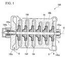
- Fig. 1 is a sectional view showing a schematic constitution of a centrifugal compressor 100 equipped with the rotary machine of this embodiment.
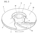
- Fig. 2 is a perspective view of an impeller in a first embodiment of this invention.
- Fig. 3 is a sectional view of the impeller in the first embodiment of this invention.
- a rotary shaft 5 is supported on a casing 105 of the centrifugal compressor 100 via journal bearings 105a and a thrust bearing 105b.
- the rotary shaft 5 can be rotated about an axis O.
- a plurality of impellers 10 are mounted on this rotary shaft 5 in parallel in a direction of the axis O.
- each of the impellers 10 has approximately a disk shape.
- Each of the impellers 10 is configured to discharge a fluid suctioned from an inlet 2 opened at one side thereof in the direction of the axis O toward an outer circumferential side in a radial direction via flow passages 104 formed inside the impeller 10.
- Each of the impellers 10 gradually compresses a gas G supplied from an upstream flow passage 104 formed in the casing 105 using a centrifugal force caused by rotation of the rotary shaft 5, and discharges the compressed gas G to a downstream flow passage 104.
- the casing 105 is formed with a suction port 105c for causing the gas G to flow in from the outside at a front side (a left side in Fig. 1 ) of the rotary shaft 5 in the direction of the axis O.
- the casing 105 is also formed with a discharge port 105d for causing the gas G to flow out to the outside at a rear side (a right side in Fig. 1 ) in the direction of the axis O.
- the left side of the page is referred to as "front side”
- the right side of the page is referred to as "rear side.”
- the gas G flows from the suction port 105c into the flow passage 104.
- This gas G is compressed by the impellers 10 in a step-by-step manner, and is discharged from the discharge port 105d.
- Fig. 1 an example in which six impellers 10 are provided for the rotary shaft 5 in series is shown, but at least one impeller 10 may be provided for the rotary shaft 5.
- only one impeller 10 is provided for the rotary shaft 5 will be described by way of example.
- the impeller 10 is equipped with a disk section 30, blade sections 40, and a cover section 50.
- the disk section 30 is fitted from the outside in the radial direction, and thereby is mounted on the rotary shaft 5.
- the disk section 30 is provided with a first member 31 and a second member 32 that are axially divided from each other by a dividing plane B orthogonal to the axis O. These first and second members 31 and 32 are joined on the dividing plane B.
- the first member 31 has an approximately cylindrical shape whose center is the axis O.
- the first member 31 is provided with a grip section A fitted around the rotary shaft 5 at the side of a first end 33 thereof at the front side in the direction of the axis O.
- the first member 31 is also provided with an enlarged diameter section 34 whose diameter is gradually enlarged toward the rear side in the direction of the axis O.
- An outer circumferential surface of the enlarged diameter section 34 becomes a curved surface recessed toward the outside in a cross section including the axis O.
- an end face 35 of the first member 31 at the rear side in the direction of the axis O is joined to the second member 32.
- a method of fitting the first member 31 around the rotary shaft 5 at the above grip section A is a method of using thermal deformation, and for instance, cold-fitting or shrink-fitting may be used.
- the impeller 10 is mounted on the rotary shaft 5 by the grip section A only.
- the second member 32 is formed in a disk shape that extends from the side of a second end 36, which is opposite to the side of the first end 33 in the direction of the axis O, toward the outside in the radial direction.
- a base-section-side region 32b of a front side surface 32a of the second member 32 is joined with the end face 35 of the first member 31.
- the end face 35 and the base-section-side region 32b of the front side surface 32a constitute the dividing plane B orthogonal to the axis O.
- to be orthogonal to the axis O refers to extending in a radial direction of the disk section 30.
- the first member 31 and the second member 32 are joined on the dividing plane B by brazing or friction stir welding (FSW).
- FSW friction stir welding
- the plurality of blade sections 40 are arranged in a circumferential direction of the disk section 30 at predetermined intervals.
- the blade sections 40 are formed with a nearly constant strip thickness, and are formed to protrude from the front side surface 32a of the disk section 30 toward the front side in the direction of the axis O. Also, as shown in Fig. 3 , the blade sections 40 are formed to be slightly tapered toward the outside in the radial direction in a side view.
- each of the blade sections 40 when viewed in the direction of the axis O, each of the blade sections 40 is formed to face a rear side in a rotating direction of the impeller 10 toward the outside of the disk section 30 in the radial direction. Also, when viewed in the direction of the axis O, each of the blade sections 40 is formed to be bent in a concave shape recessed toward a rear side in a rotating direction of the axis.
- the blade sections 40 may extend to the rear side in the rotating direction toward the outside in the radial direction.
- the blade sections 40 may be linearly formed.
- the cover section 50 covers the blade sections 40 from the side of the first end 33 in the direction of the axis O.
- a rear side surface 50a of the cover section 50 in the direction of the axis O is integrally mounted on front side edges 40a of the blade sections 40.
- the thickness of the cover section 50 is formed in a sheet shape in which the thickness toward the outward in the radial direction is slightly thin.
- This cover section 50 has a flexure section 51, which is bent toward the front side in the direction of the axis O, at positions of inner ends 40b of the blade sections 40.
- the enlarged diameter section 34 and the dividing plane B are disposed at inner sides of the blade sections 40 in the radial direction.
- the first end 33 of the first member 31 is disposed at the front side in the direction of the axis O relative to a front side edge 51a of the flexure section 51.
- the flow passages 104 along which the gas G flows are defined by an outer circumferential surface 31a of the first member 31, the front side surface 32a of the second member 32, lateral surfaces 40c of the blade sections 40, and a rear side surface 50a of the cover section 50.
- the first member 31 is formed by casting or cutting (step S01).
- the second member 32 is formed integrally with the blade sections 40 and the cover section 50 (step S02).
- the second member 32, the blade sections 40, and the cover section 50 are integrally formed by cutting one base material such as precipitation hardening stainless steel.
- first member 31 and the second member 32 are joined at the dividing plane B (step S03).
- base-section-side region 32b of the front side surface 32a of the second member 32 and the end face 35 of the first member 31 are joined by brazing or FSW.
- the grip section A of the first member 31 is fitted at a predetermined position of the outer circumferential surface 5a of the rotary shaft 5 by shrink-fitting (step S04).
- the second member 32 can be machined in a state in which no member is disposed at an inner side in the radial direction relative to the blade sections 40. Also, since the first member 31 and the second member 32 are joined on the dividing plane B, it is unnecessary to individually mount the first member 31 and the second member 32 on the rotary shaft 5. In addition, when the first member is mounted on the rotary shaft 5 using the thermal deformation, the grip section A at the side of the first end 33 in the direction of the axis O is fixed to the rotary shaft 5, and thus a temperature can be raised faster than when the side of the second end 36 that extends outward in the radial direction and has a large cross-sectional area is fixed. Further, since the dividing plane B is orthogonal to the axis O, welding work can be easily performed, compared to a case in which the dividing plane B is oblique.
- centrifugal compressor 100 of the aforementioned first embodiment it is possible to easily perform maintenance of the impeller 10 and to suppress a variation in quality to improve merchantability.
- the dividing plane B of the impeller 10 is joined by the brazing or the FSW. For this reason, the first member 31 can be easily welded to the second member 32.
- the impeller 10 of the aforementioned first embodiment machinability of the flow passages 104 defined by the disk section 30, the blade sections 40, and the cover section 50 can be improved.
- the first member 31 and the second member 32 after the first member 31 and the second member 32 are joined, the first member 31 can be fixed to the rotary shaft 5 and thus be easily mounted on and dismounted from the rotary shaft 5.
- first member 31 and the second member 32 are brazed, the first member 31 and the second member 32 are heated to about 900°C. Also, when the first member 31 is joined to the rotary shaft 5 by the shrink-fitting, the first member 31 and the second member 32 are heated to about 500°C that is lower than the temperature of the brazing. For this reason, the first member 31 and the second member 32 are brazed and then shrink-fitted, and thereby assembly can be smoothly performed by the heating caused by the shrink-fitting without exerting an adverse influence on the joined portion between the first member 31 and the second member 32.
- the impeller of the second embodiment is different from the impeller 10 of the aforementioned first embodiment only in that a step section is formed on the dividing plane B. For this reason, the same portions as in the aforementioned first embodiment will be given the same reference signs and be described, and duplicate descriptions will be omitted.
- Fig. 5 is a sectional view equivalent to Fig. 3 in the second embodiment of this invention.
- the impeller 110 in the second embodiment is equipped with a disk section 30, blade sections 40, and a cover section 50.
- a detailed description of the blade sections 40 and the cover section 50 will be omitted because they have the same constitutions as in the aforementioned first embodiment.
- the disk section 30 is equipped with a first member 131 and the second member 132.
- the first member 131 has an approximately cylindrical shape whose center is an axis O.
- the first member 131 is provided with a grip section A fitted around a rotary shaft 5 at the side of a first end 33 thereof at a front side in a direction of the axis O.
- the grip section A is fitted around the rotary shaft 5 from the outside by a method using thermal deformation.
- cold-fitting or shrink-fitting may be used as this fitting method.
- the first member 131 is provided with an enlarged diameter section 34 whose diameter is gradually enlarged toward a rear side in the direction of the axis O.
- An outer circumferential surface of the enlarged diameter section 34 becomes a curved surface recessed toward the outside in a cross section including the axis O. Also, an end face 35 of the first member 131 at the rear side in the direction of the axis O is joined to the second member 132.
- the second member 132 is formed in a disk shape that extends outward in a radial direction from the side of a second end 36 thereof in the direction of the axis O.
- a base-section-side region 32b of a front side surface 32a of the second member 132 is joined with the end face 35 of the first member 131.
- the end face 35 and the base-section-side region 32b of the front side surface 32a constitute the dividing plane B that is orthogonal to the axis O and divides the disk section 30 into the two parts.
- the disk section 30 has a step section 37 on the dividing plane B thereof.
- This step section 37 regulates the second member 132 from being displaced toward an outer circumferential side in the radial direction with respect to the first member 131.
- the step section 37 is formed in the dividing plane B in a radial direction, more particularly at a middle section of the dividing plane B in the radial direction.
- Fig. 6 is an enlarged view of the step section 37 in the second embodiment of this invention.
- the step section 37 is provided with a backing face 38 and a mating face 39.
- the backing face 38 is formed at the first member 131, and faces an inner side in the radial direction.
- the mating face 39 is formed at the second member 132, and faces the outside in the radial direction.
- the backing face 38 and the mating face 39 are formed around the rotary shaft 5 in an annular shape.
- the disk section 30 is formed with a concave groove in a circumferential edge of an opening at the side of the end face 35 of a through-hole 11 of the first member 131 into which the rotary shaft 5 is inserted.
- the disk section 30 is also formed with a convex portion that can be fitted into the concave groove in a circumferential edge of an opening at the side of the base-section-side region 32b of a through-hole 12 of the second member 132 into which the rotary shaft 5 is inserted.
- a reference sign S indicates a joined portion.
- a brazing material is disposed at the joined portion S.
- the second member 132 can be easily positioned for the first member 131. Also, since displacement of the second member 132 toward the outside in the radial direction is regulated by the step section 37, a force acting on the dividing plane B in a shearing direction can be limited. For this reason, it is possible to improve the joining strength. For example, it is also possible to suppress deformation of the second member 132 having larger mass than the first member 131 toward the outside in the radial direction due to a centrifugal force.
- the grip section A is provided only at the side of the first end 33 .
- the grip section A may be at least provided at the side of the first end 33.
- fitting may be used at another position of, for instance, the side of the second end 36 in combination.
- the step section 37 is not limited to only the single step section.
- a plurality of step sections 37a and 37b may be configured to be provided.
- the number of step sections is not limited to two.
- the brazing material may also be configured to be disposed and brazed at the step section 37.
- the dividing plane B is disposed on an extension surface of the front side surface 32a of the second member 32 on which the blade sections 40 are mounted has been described, but the invention is not limited thereto.
- the dividing plane B may be disposed on the blade sections 40, more particularly at the inner sides of the inner ends 40b of the blade sections 40 in the radial direction, and extend in the direction orthogonal to the axis O.
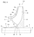
- Fig. 8 shows an impeller 210 in a modification of the aforementioned first embodiment. Since this impeller 210 is merely different in shape from the impeller 10 of the aforementioned first embodiment, the same reference signs are given to the same portions. As shown in Fig. 8 , for example, the dividing plane B may be disposed at the side of the first end 33 in the direction of the axis O relative to the position of the front side surface 32a on which the blade sections 40 are mounted within the front side surface 32a.
- the impeller 10 or 110 is applied to the centrifugal compressor 100 .
- the rotary machine capable of applying the impeller 10 or 110 is not limited to the centrifugal compressor 100.
- the impeller 10 or 110 can also be applied to, for example, various industrial compressors or turbo refrigerators, or small gas turbines.
- the impeller According to the impeller, the rotary machine, and the impeller manufacturing method, it is possible to improve quality of shape in the flow passages and easily perform mounting on and dismounting from the rotary shaft.
Landscapes
- Engineering & Computer Science (AREA)
- Mechanical Engineering (AREA)
- General Engineering & Computer Science (AREA)
- Structures Of Non-Positive Displacement Pumps (AREA)
Abstract
Description
- The present invention relates to an impeller, a rotary machine, and an impeller manufacturing method.
- Priority is claimed on
Japanese Patent Application No. 2013-240921, filed on November 21, 2013 - Rotary machines used in, for instance, industrial compressors, turbo refrigerators, small gas turbines, etc. are equipped with an impeller in which a plurality of blades are mounted on a disk fixed to a rotary shaft. These rotary machines rotate the impeller to give pressure energy and kinematic energy to a gas.
- As the above impeller, a so-called closed impeller in which a cover is integrally mounted on the blades is known. This closed impeller may have a structure in which a plurality of parts are joined and assembled. When the impeller has this joined structure, there is a tendency for quality of shape in flow passages and performance of the impeller to decrease. For this reason, the impeller is made in one piece. However, when the impeller is made in one piece, complicated cutting and welding are required, and it takes time to assemble the impeller.
- In
Patent Literature 1, a technology in which a first member in which a disk section, a blade section, and a cover section that form flow passages are made in one piece and a second member located at one side of the disk section in an axial direction are separately formed, and thereby accessibility of machining tools to the first member can be improved is proposed. - [Patent Literature 1]
Japanese Unexamined Patent Application, First Publication No. 2013-47479 - The aforementioned impeller may be mounted on the rotary shaft using thermal deformation. When the impeller is mounted on the rotary shaft using the thermal deformation in this way, if the disk section is divided into the first and second members, the first and second members should be individually mounted on or dismounted from the rotary shaft. Thus, there is a problem that in the task of mounting on and dismounting from the rotary shaft is complicated. For example, when the first member is mounted on the rotary shaft by the thermal deformation and then the second member is mounted on the rotary shaft by the thermal deformation, there is a possibility of heat of the second member being transmitted to the first member and a position of the first member being shifted.
- The present invention provides: an impeller capable of improving quality of shape in flow passages and that can easily be mounted on and dismounted from a rotary shaft; a rotary machine; and an impeller manufacturing method.
- According to a first aspect of the present invention, an impeller includes: a disk section having at least a first end side which is fixed to a rotary shaft which rotates about an axis, and extending outward in a radial direction to a second end side which opposite to the first end side in the direction of the axis from the first end side; blade sections provided to protrude from the disk section to the first end side in the direction of the axis; and a cover section integrally provided for the blade sections and configured to cover the blade sections from the first end side in the direction of the axis. The disk section includes a first member and a second member that are divided from each other in the direction of the axis by a dividing plane which is orthogonal to the axis, at inner sides of the blade sections in the radial direction. The first member and the second member are joined on the dividing plane.
- With this constitution, the second member can be machined in a state in which no member is disposed at the inner sides of the blade sections in the radial direction. Also, since the first member and the second member are joined on the dividing plane, it is unnecessary to individually mount the first member and the second member on the rotary shaft. In addition, when the first member is mounted on the rotary shaft using thermal deformation, at least the first end side in the direction of the axis is fixed to the rotary shaft, and thus a temperature can be raised faster than when the second end side that extends outward in the radial direction and has a large cross-sectional area is fixed. Further, since the dividing plane is orthogonal to the axis, welding work can be easily performed, compared to a case in which the dividing plane is oblique.
- According to a second aspect of the present invention, in the impeller, the dividing plane may have a step section which regulates the second member from being displaced toward an outer circumferential side in the radial direction with respect to the first member.
- With this constitution, the second member can be easily positioned for the first member. Also, since displacement of the second member toward the outside in the radial direction is regulated by the step section, a force acting on the dividing plane in a shearing direction can be suppressed. For this reason, it is possible to improve the joining strength. For example, it is also possible to suppress the deformation of the second member having larger mass than the first member toward the outside in the radial direction.
- According to a third aspect of the present invention, the dividing plane of the impeller may be joined by brazing or friction stir welding.
- With this constitution, the first member can be easily joined to the second member.
- According to a fourth aspect of the present invention, a rotary machine includes the above impeller.
- With this constitution, it is possible to easily perform maintenance of the impeller and to suppress a variation in quality to improve merchantability.
- According to a fourth aspect of the present invention, an impeller manufacturing method in which an impeller includes: a disk section fixed to a rotary shaft, which rotates about an axis, at least at a first end side in a direction of the axis and configured to extend outward in a radial direction from a second end side opposite to the first end side in the direction of the axis; blade sections provided to protrude from the disk section to the first end side in the direction of the axis; and a cover section integrally provided for the blade sections and configured to cover the blade sections from the first end side in the direction of the axis, wherein the disk section includes a first member and a second member that are divided from each other in the direction of the axis by a dividing plane, which is orthogonal to the axis, at inner sides of the blade sections in the radial direction. The impeller manufacturing method includes: a process of forming the first member; a process of forming the second member in which the blade sections, the cover section, and the disk section are integrally formed; a process of joining the first member and the second member; and a process of at least fixing the first member to the rotary shaft.
- With this constitution, machinability of flow passages defined by the disk section, the blade sections, and the cover section can be improved. Also, after the first member and the second member are joined, the first member can be fixed to the rotary shaft, and thus be easily mounted on and dismounted from the rotary shaft.
- According to the aforementioned impeller, rotary machine, and impeller manufacturing method, it is possible to improve quality of shape in flow passages and to easily perform mounting on and dismounting from the rotary shaft.
-
-
Fig. 1 is a sectional view of a centrifugal compressor in a first embodiment of this invention. -
Fig. 2 is a perspective view of an impeller in a first embodiment of this invention. -
Fig. 3 is a sectional view of the impeller in the first embodiment of this invention. -
Fig. 4 is a flow chart showing an impeller manufacturing method in a first embodiment of this invention. -
Fig. 5 is a sectional view equivalent toFig. 3 in a second embodiment of this invention. -
Fig. 6 is an enlarged view of a step section in the second embodiment of this invention. -
Fig. 7 is a sectional view equivalent toFig. 6 in a modification of the second embodiment of this invention. -
Fig. 8 is a sectional view equivalent toFig. 6 in a modification of the first embodiment of this invention. - Next, a rotary machine in a first embodiment of this invention will be described with reference to the drawings.
-
Fig. 1 is a sectional view showing a schematic constitution of acentrifugal compressor 100 equipped with the rotary machine of this embodiment.Fig. 2 is a perspective view of an impeller in a first embodiment of this invention.Fig. 3 is a sectional view of the impeller in the first embodiment of this invention. - As shown in
Fig. 1 , arotary shaft 5 is supported on acasing 105 of thecentrifugal compressor 100 viajournal bearings 105a and a thrust bearing 105b. Therotary shaft 5 can be rotated about an axis O. A plurality ofimpellers 10 are mounted on thisrotary shaft 5 in parallel in a direction of the axis O. - As shown in
Fig. 2 , each of theimpellers 10 has approximately a disk shape. Each of theimpellers 10 is configured to discharge a fluid suctioned from aninlet 2 opened at one side thereof in the direction of the axis O toward an outer circumferential side in a radial direction viaflow passages 104 formed inside theimpeller 10. - Each of the
impellers 10 gradually compresses a gas G supplied from anupstream flow passage 104 formed in thecasing 105 using a centrifugal force caused by rotation of therotary shaft 5, and discharges the compressed gas G to adownstream flow passage 104. - As shown in
Fig. 1 , thecasing 105 is formed with asuction port 105c for causing the gas G to flow in from the outside at a front side (a left side inFig. 1 ) of therotary shaft 5 in the direction of the axis O. Thecasing 105 is also formed with adischarge port 105d for causing the gas G to flow out to the outside at a rear side (a right side inFig. 1 ) in the direction of the axis O. In the following description, the left side of the page is referred to as "front side," and the right side of the page is referred to as "rear side." - According to the above
centrifugal compressor 100, if therotary shaft 5 is rotated, the gas G flows from thesuction port 105c into theflow passage 104. This gas G is compressed by theimpellers 10 in a step-by-step manner, and is discharged from thedischarge port 105d. InFig. 1 , an example in which siximpellers 10 are provided for therotary shaft 5 in series is shown, but at least oneimpeller 10 may be provided for therotary shaft 5. In the following description, to simplify the description, a case in which only oneimpeller 10 is provided for therotary shaft 5 will be described by way of example. - As shown in
Figs. 2 and3 , theimpeller 10 is equipped with adisk section 30,blade sections 40, and acover section 50. - The
disk section 30 is fitted from the outside in the radial direction, and thereby is mounted on therotary shaft 5. Thedisk section 30 is provided with afirst member 31 and asecond member 32 that are axially divided from each other by a dividing plane B orthogonal to the axis O. These first andsecond members - The
first member 31 has an approximately cylindrical shape whose center is the axis O. Thefirst member 31 is provided with a grip section A fitted around therotary shaft 5 at the side of afirst end 33 thereof at the front side in the direction of the axis O. Thefirst member 31 is also provided with anenlarged diameter section 34 whose diameter is gradually enlarged toward the rear side in the direction of the axis O. An outer circumferential surface of theenlarged diameter section 34 becomes a curved surface recessed toward the outside in a cross section including the axis O. Also, anend face 35 of thefirst member 31 at the rear side in the direction of the axis O is joined to thesecond member 32. Here, a method of fitting thefirst member 31 around therotary shaft 5 at the above grip section A is a method of using thermal deformation, and for instance, cold-fitting or shrink-fitting may be used. In this embodiment, theimpeller 10 is mounted on therotary shaft 5 by the grip section A only. - The
second member 32 is formed in a disk shape that extends from the side of asecond end 36, which is opposite to the side of thefirst end 33 in the direction of the axis O, toward the outside in the radial direction. A base-section-side region 32b of afront side surface 32a of thesecond member 32 is joined with theend face 35 of thefirst member 31. Theend face 35 and the base-section-side region 32b of thefront side surface 32a constitute the dividing plane B orthogonal to the axis O. Here, to be orthogonal to the axis O refers to extending in a radial direction of thedisk section 30. - The
first member 31 and thesecond member 32 are joined on the dividing plane B by brazing or friction stir welding (FSW). - The plurality of
blade sections 40 are arranged in a circumferential direction of thedisk section 30 at predetermined intervals. - The
blade sections 40 are formed with a nearly constant strip thickness, and are formed to protrude from thefront side surface 32a of thedisk section 30 toward the front side in the direction of the axis O. Also, as shown inFig. 3 , theblade sections 40 are formed to be slightly tapered toward the outside in the radial direction in a side view. - As shown in
Fig. 2 , when viewed in the direction of the axis O, each of theblade sections 40 is formed to face a rear side in a rotating direction of theimpeller 10 toward the outside of thedisk section 30 in the radial direction. Also, when viewed in the direction of the axis O, each of theblade sections 40 is formed to be bent in a concave shape recessed toward a rear side in a rotating direction of the axis. Here, one example in which theblade sections 40 are formed to be bent when viewed in the direction of the axis O is described, but theblade sections 40 may extend to the rear side in the rotating direction toward the outside in the radial direction. For example, when viewed in the direction of the axis O, theblade sections 40 may be linearly formed. - In
Fig. 2 , the rotating direction of theimpeller 10 is indicated by an arrow. - The
cover section 50 covers theblade sections 40 from the side of thefirst end 33 in the direction of the axis O. Arear side surface 50a of thecover section 50 in the direction of the axis O is integrally mounted on front side edges 40a of theblade sections 40. Similar to the thickness of thedisk section 30, the thickness of thecover section 50 is formed in a sheet shape in which the thickness toward the outward in the radial direction is slightly thin. Thiscover section 50 has aflexure section 51, which is bent toward the front side in the direction of the axis O, at positions ofinner ends 40b of theblade sections 40. - In the
impeller 10 configured as described above, theenlarged diameter section 34 and the dividing plane B are disposed at inner sides of theblade sections 40 in the radial direction. Also, thefirst end 33 of thefirst member 31 is disposed at the front side in the direction of the axis O relative to afront side edge 51a of theflexure section 51. Theflow passages 104 along which the gas G flows are defined by an outercircumferential surface 31a of thefirst member 31, thefront side surface 32a of thesecond member 32, lateral surfaces 40c of theblade sections 40, and arear side surface 50a of thecover section 50. - Next, a method of manufacturing the
aforementioned impeller 10 will be described with reference to a flow chart ofFig. 4 . - First, the
first member 31 is formed by casting or cutting (step S01). - Next, the
second member 32 is formed integrally with theblade sections 40 and the cover section 50 (step S02). To be more specific, thesecond member 32, theblade sections 40, and thecover section 50 are integrally formed by cutting one base material such as precipitation hardening stainless steel. - Also, the
first member 31 and thesecond member 32 are joined at the dividing plane B (step S03). To be more specific, the base-section-side region 32b of thefront side surface 32a of thesecond member 32 and theend face 35 of thefirst member 31 are joined by brazing or FSW. - Afterwards, the grip section A of the
first member 31 is fitted at a predetermined position of the outercircumferential surface 5a of therotary shaft 5 by shrink-fitting (step S04). - Therefore, according to the
impeller 10 of the aforementioned first embodiment, thesecond member 32 can be machined in a state in which no member is disposed at an inner side in the radial direction relative to theblade sections 40. Also, since thefirst member 31 and thesecond member 32 are joined on the dividing plane B, it is unnecessary to individually mount thefirst member 31 and thesecond member 32 on therotary shaft 5. In addition, when the first member is mounted on therotary shaft 5 using the thermal deformation, the grip section A at the side of thefirst end 33 in the direction of the axis O is fixed to therotary shaft 5, and thus a temperature can be raised faster than when the side of thesecond end 36 that extends outward in the radial direction and has a large cross-sectional area is fixed. Further, since the dividing plane B is orthogonal to the axis O, welding work can be easily performed, compared to a case in which the dividing plane B is oblique. - As a result, quality of shape in the
flow passages 104 can be improved, and the first member can be easily mounted on and dismounted from therotary shaft 5. - Also, according to the
centrifugal compressor 100 of the aforementioned first embodiment, it is possible to easily perform maintenance of theimpeller 10 and to suppress a variation in quality to improve merchantability. - Further, the dividing plane B of the
impeller 10 is joined by the brazing or the FSW. For this reason, thefirst member 31 can be easily welded to thesecond member 32. - Also, according to the method of manufacturing the
impeller 10 of the aforementioned first embodiment, machinability of theflow passages 104 defined by thedisk section 30, theblade sections 40, and thecover section 50 can be improved. In addition, after thefirst member 31 and thesecond member 32 are joined, thefirst member 31 can be fixed to therotary shaft 5 and thus be easily mounted on and dismounted from therotary shaft 5. - Further, when the
first member 31 and thesecond member 32 are brazed, thefirst member 31 and thesecond member 32 are heated to about 900°C. Also, when thefirst member 31 is joined to therotary shaft 5 by the shrink-fitting, thefirst member 31 and thesecond member 32 are heated to about 500°C that is lower than the temperature of the brazing. For this reason, thefirst member 31 and thesecond member 32 are brazed and then shrink-fitted, and thereby assembly can be smoothly performed by the heating caused by the shrink-fitting without exerting an adverse influence on the joined portion between thefirst member 31 and thesecond member 32. - Next, an impeller in a second embodiment of this invention will be described on the basis of the drawings. The impeller of the second embodiment is different from the
impeller 10 of the aforementioned first embodiment only in that a step section is formed on the dividing plane B. For this reason, the same portions as in the aforementioned first embodiment will be given the same reference signs and be described, and duplicate descriptions will be omitted. -
Fig. 5 is a sectional view equivalent toFig. 3 in the second embodiment of this invention. - As shown in
Fig. 5 , theimpeller 110 in the second embodiment is equipped with adisk section 30,blade sections 40, and acover section 50. A detailed description of theblade sections 40 and thecover section 50 will be omitted because they have the same constitutions as in the aforementioned first embodiment. - The
disk section 30 is equipped with afirst member 131 and thesecond member 132. - The
first member 131 has an approximately cylindrical shape whose center is an axis O. Thefirst member 131 is provided with a grip section A fitted around arotary shaft 5 at the side of afirst end 33 thereof at a front side in a direction of the axis O. The grip section A is fitted around therotary shaft 5 from the outside by a method using thermal deformation. Like the first embodiment, for instance, cold-fitting or shrink-fitting may be used as this fitting method. - The
first member 131 is provided with anenlarged diameter section 34 whose diameter is gradually enlarged toward a rear side in the direction of the axis O. - An outer circumferential surface of the
enlarged diameter section 34 becomes a curved surface recessed toward the outside in a cross section including the axis O. Also, anend face 35 of thefirst member 131 at the rear side in the direction of the axis O is joined to thesecond member 132. - The
second member 132 is formed in a disk shape that extends outward in a radial direction from the side of asecond end 36 thereof in the direction of the axis O. A base-section-side region 32b of afront side surface 32a of thesecond member 132 is joined with theend face 35 of thefirst member 131. Theend face 35 and the base-section-side region 32b of thefront side surface 32a constitute the dividing plane B that is orthogonal to the axis O and divides thedisk section 30 into the two parts. - The
disk section 30 has astep section 37 on the dividing plane B thereof. Thisstep section 37 regulates thesecond member 132 from being displaced toward an outer circumferential side in the radial direction with respect to thefirst member 131. Thestep section 37 is formed in the dividing plane B in a radial direction, more particularly at a middle section of the dividing plane B in the radial direction. -
Fig. 6 is an enlarged view of thestep section 37 in the second embodiment of this invention. - As shown in
Fig. 6 , thestep section 37 is provided with abacking face 38 and amating face 39. - The
backing face 38 is formed at thefirst member 131, and faces an inner side in the radial direction. - The
mating face 39 is formed at thesecond member 132, and faces the outside in the radial direction. - The
backing face 38 and themating face 39 are formed around therotary shaft 5 in an annular shape. - In other words, as shown in
Fig. 5 , thedisk section 30 is formed with a concave groove in a circumferential edge of an opening at the side of theend face 35 of a through-hole 11 of thefirst member 131 into which therotary shaft 5 is inserted. Thedisk section 30 is also formed with a convex portion that can be fitted into the concave groove in a circumferential edge of an opening at the side of the base-section-side region 32b of a through-hole 12 of thesecond member 132 into which therotary shaft 5 is inserted. - As shown in
Fig. 6 , theend face 35 and the base-section-side region 32b of thefront side surface 32a are joined on the dividing plane B. That is, thefirst member 131 and thesecond member 132 are joined only on a surface extending in a radial direction. InFig. 6 , a reference sign S indicates a joined portion. In the case of brazing, a brazing material is disposed at the joined portion S. - Therefore, according to the
impeller 110 of the aforementioned second embodiment, thesecond member 132 can be easily positioned for thefirst member 131. Also, since displacement of thesecond member 132 toward the outside in the radial direction is regulated by thestep section 37, a force acting on the dividing plane B in a shearing direction can be limited. For this reason, it is possible to improve the joining strength. For example, it is also possible to suppress deformation of thesecond member 132 having larger mass than thefirst member 131 toward the outside in the radial direction due to a centrifugal force. - This invention is not limited to the constitution of each of the aforementioned embodiments, and can be changed in design without departing from the scope thereof.
- In each of the aforementioned embodiments, the case in which the
first member second member - Also, the case in which the grip section A is provided only at the side of the
first end 33 has been described. However, the grip section A may be at least provided at the side of thefirst end 33. For example, fitting may be used at another position of, for instance, the side of thesecond end 36 in combination. - Further, in the aforementioned second embodiment, one example in which only the
single step section 37 is formed has been described. However, thestep section 37 is not limited to only the single step section. For example, as shown inFig. 7 , a plurality ofstep sections step section 37 has been described. However, the brazing material may also be configured to be disposed and brazed at thestep section 37. - In each of the aforementioned second embodiments, the case in which the dividing plane B is disposed on an extension surface of the
front side surface 32a of thesecond member 32 on which theblade sections 40 are mounted has been described, but the invention is not limited thereto. The dividing plane B may be disposed on theblade sections 40, more particularly at the inner sides of the inner ends 40b of theblade sections 40 in the radial direction, and extend in the direction orthogonal to the axis O. -
Fig. 8 shows animpeller 210 in a modification of the aforementioned first embodiment. Since thisimpeller 210 is merely different in shape from theimpeller 10 of the aforementioned first embodiment, the same reference signs are given to the same portions. As shown inFig. 8 , for example, the dividing plane B may be disposed at the side of thefirst end 33 in the direction of the axis O relative to the position of thefront side surface 32a on which theblade sections 40 are mounted within thefront side surface 32a. - Further, in each of the aforementioned embodiments, the case in which the
impeller centrifugal compressor 100 has been described. However, the rotary machine capable of applying theimpeller centrifugal compressor 100. Theimpeller - According to the impeller, the rotary machine, and the impeller manufacturing method, it is possible to improve quality of shape in the flow passages and easily perform mounting on and dismounting from the rotary shaft.
-
- 5:
- Rotary shaft
- 5a:
- Outer circumferential surface
- 10:
- Impeller
- 11:
- Through-hole
- 30:
- Disk section
- 31:
- First member
- 31a:
- Outer circumferential surface
- 32:
- Second member
- 32a:
- Front side surface
- 32b:
- Base section-side region
- 33:
- First end
- 34:
- Enlarged diameter section
- 35:
- End face
- 36:
- Second end
- 37:
- Step section
- 38:
- Backing face
- 39:
- Mating face
- 40:
- Blade section
- 40a:
- Front side edge
- 40b:
- Inner end
- 40c:
- Lateral surface
- 50:
- Cover section
- 50a:
- Rear side surface
- 51:
- Flexure section
- 51a:
- Front side edge
- 100:
- Centrifugal compressor
- 104:
- Flow passage
- 105:
- Casing
- 105a:
- Journal bearing
- 105b:
- Thrust bearing
- 105c:
- Suction port
- 105d:
- Discharge port
- A:
- Grip section
- B:
- Dividing plane
- G:
- Gas
- O:
- Axis
Claims (5)
- An impeller comprising:a disk section fixed to a rotary shaft, which rotates about an axis, at least at a first end side in a direction of the axis and configured to extend outward in a radial direction from a second end side opposite to the first end side in the direction of the axis;blade sections provided to protrude from the disk section to the first end side in the direction of the axis; anda cover section integrally provided for the blade sections and configured to cover the blade sections from the first end side in the direction of the axis;wherein the disk section includes a first member and a second member that are divided from each other in the direction of the axis by a dividing plane, which is orthogonal to the axis, at inner sides of the blade sections in the radial direction; andwherein the first member and the second member are joined on the dividing plane.
- The impeller according to claim 1, wherein the dividing plane has a step section which is configured to regulate the second member which is displaced toward an outer circumferential side in the radial direction with respect to the first member.
- The impeller according to claim 1 or 2, wherein the dividing plane is joined by brazing or friction stir welding.
- A rotary machine comprising the impeller according to any one of claims 1 to 3.
- An impeller manufacturing method in which an impeller comprises:a disk section fixed to a rotary shaft, which rotates about an axis, at least at a first end side in a direction of the axis and configured to extend outward in a radial direction from a second end side opposite to the first end side in the direction of the axis;blade sections provided to protrude from the disk section to the first end side in the direction of the axis; anda cover section integrally provided for the blade sections and configured to cover the blade sections from the first end side in the direction of the axis,wherein the disk section includes a first member and a second member that are divided from each other in the direction of the axis by a dividing plane, which is orthogonal to the axis, at inner sides of the blade sections in the radial direction;the impeller manufacturing method comprising:a process of forming the first member;a process of forming the second member in which the blade sections, the cover section, and the disk section are integrally formed;a process of joining the first member and the second member; anda process of at least fixing the first member to the rotary shaft.
Applications Claiming Priority (2)
| Application Number | Priority Date | Filing Date | Title |
|---|---|---|---|
| JP2013240921A JP6327505B2 (en) | 2013-11-21 | 2013-11-21 | Impeller and rotating machine |
| PCT/JP2014/080335 WO2015076217A1 (en) | 2013-11-21 | 2014-11-17 | Impeller, rotary machine, and impeller manufacturing method |
Publications (3)
| Publication Number | Publication Date |
|---|---|
| EP3059454A1 true EP3059454A1 (en) | 2016-08-24 |
| EP3059454A4 EP3059454A4 (en) | 2016-11-16 |
| EP3059454B1 EP3059454B1 (en) | 2019-09-18 |
Family
ID=53179480
Family Applications (1)
| Application Number | Title | Priority Date | Filing Date |
|---|---|---|---|
| EP14864299.4A Active EP3059454B1 (en) | 2013-11-21 | 2014-11-17 | Impeller, rotary machine, and impeller manufacturing method |
Country Status (5)
| Country | Link |
|---|---|
| US (1) | US10443605B2 (en) |
| EP (1) | EP3059454B1 (en) |
| JP (1) | JP6327505B2 (en) |
| CN (1) | CN105765233A (en) |
| WO (1) | WO2015076217A1 (en) |
Cited By (1)
| Publication number | Priority date | Publication date | Assignee | Title |
|---|---|---|---|---|
| EP3557076A4 (en) * | 2017-02-20 | 2019-12-18 | Mitsubishi Heavy Industries Compressor Corporation | TURBINE, ROTARY MACHINE, METHOD FOR MANUFACTURING TURBINE, AND METHOD FOR MANUFACTURING ROTARY MACHINE |
Families Citing this family (5)
| Publication number | Priority date | Publication date | Assignee | Title |
|---|---|---|---|---|
| CN105003302B (en) * | 2014-04-18 | 2017-04-12 | 松下知识产权经营株式会社 | Turbine engine |
| JP2018095301A (en) * | 2016-12-15 | 2018-06-21 | 株式会社イシダ | Bag making and packaging machine |
| JP6789165B2 (en) * | 2017-03-30 | 2020-11-25 | 三菱重工コンプレッサ株式会社 | Impeller manufacturing method |
| JP6936126B2 (en) | 2017-11-29 | 2021-09-15 | 三菱重工コンプレッサ株式会社 | Impeller, rotating machine |
| CN115045863A (en) * | 2022-07-01 | 2022-09-13 | 中国航发沈阳发动机研究所 | Fan casing structure of aircraft engine |
Family Cites Families (17)
| Publication number | Priority date | Publication date | Assignee | Title |
|---|---|---|---|---|
| US1983201A (en) * | 1931-03-07 | 1934-12-04 | Bbc Brown Boveri & Cie | Rotary blower blade |
| US1953064A (en) * | 1931-12-19 | 1934-04-03 | Parsons C A & Co Ltd | Centrifugal apparatus such as fans, impellers, and the like |
| US2392858A (en) * | 1943-03-08 | 1946-01-15 | Gen Electric | High-speed rotor for centrifugal compressors and the like |
| US2936715A (en) * | 1955-11-14 | 1960-05-17 | Thompson Ramo Wooldridge Inc | Seal assembly |
| US5167678A (en) * | 1988-04-11 | 1992-12-01 | A. Ahlstrom Corporation | Apparatus for separating gas with a pump from a medium being pumped |
| JP2001355595A (en) * | 2000-06-13 | 2001-12-26 | Hitachi Ltd | Method for manufacturing pump impeller and pump using the impeller |
| US6862183B2 (en) * | 2001-10-29 | 2005-03-01 | Intel Corporation | Composite fins for heat sinks |
| ITMI20021876A1 (en) | 2002-09-03 | 2004-03-04 | Nuovo Pignone Spa | IMPROVED PROCEDURE FOR MAKING A ROTOR OF ONE |
| JP4428044B2 (en) * | 2003-03-24 | 2010-03-10 | 株式会社日立プラントテクノロジー | Impeller manufacturing method and impeller |
| JP2008121650A (en) * | 2006-11-16 | 2008-05-29 | Matsushita Electric Ind Co Ltd | Electric blower and electric vacuum cleaner using the same |
| JP2009156122A (en) | 2007-12-26 | 2009-07-16 | Mitsubishi Heavy Ind Ltd | Impeller for centrifugal compressor |
| JP5449117B2 (en) | 2010-12-08 | 2014-03-19 | 三菱重工業株式会社 | Rotating machine |
| JP5606358B2 (en) | 2011-02-24 | 2014-10-15 | 三菱重工業株式会社 | Impeller, rotor provided with the same, and method for manufacturing impeller |
| JP5787599B2 (en) | 2011-04-28 | 2015-09-30 | 三菱重工業株式会社 | Impeller |
| JP2013047479A (en) | 2011-08-29 | 2013-03-07 | Mitsubishi Heavy Ind Ltd | Impeller and rotary machine with the same, and method for manufacturing impeller |
| JP5907723B2 (en) * | 2011-12-26 | 2016-04-26 | 三菱重工業株式会社 | Manufacturing method of rotating machine |
| JP5777529B2 (en) * | 2012-01-05 | 2015-09-09 | 三菱重工業株式会社 | Impeller, rotor provided with the same, and method for manufacturing impeller |
-
2013
- 2013-11-21 JP JP2013240921A patent/JP6327505B2/en not_active Expired - Fee Related
-
2014
- 2014-11-17 EP EP14864299.4A patent/EP3059454B1/en active Active
- 2014-11-17 US US15/037,117 patent/US10443605B2/en active Active
- 2014-11-17 WO PCT/JP2014/080335 patent/WO2015076217A1/en not_active Ceased
- 2014-11-17 CN CN201480062613.6A patent/CN105765233A/en active Pending
Cited By (2)
| Publication number | Priority date | Publication date | Assignee | Title |
|---|---|---|---|---|
| EP3557076A4 (en) * | 2017-02-20 | 2019-12-18 | Mitsubishi Heavy Industries Compressor Corporation | TURBINE, ROTARY MACHINE, METHOD FOR MANUFACTURING TURBINE, AND METHOD FOR MANUFACTURING ROTARY MACHINE |
| US10982548B2 (en) | 2017-02-20 | 2021-04-20 | Mitsubishi Heavy Industries Compressor Corporation | Impeller, rotary machine, method for manufacturing impeller, and method for manufacturing rotary machine |
Also Published As
| Publication number | Publication date |
|---|---|
| US20160290354A1 (en) | 2016-10-06 |
| CN105765233A (en) | 2016-07-13 |
| JP2015101967A (en) | 2015-06-04 |
| US10443605B2 (en) | 2019-10-15 |
| JP6327505B2 (en) | 2018-05-23 |
| EP3059454A4 (en) | 2016-11-16 |
| WO2015076217A1 (en) | 2015-05-28 |
| EP3059454B1 (en) | 2019-09-18 |
Similar Documents
| Publication | Publication Date | Title |
|---|---|---|
| EP3059454B1 (en) | Impeller, rotary machine, and impeller manufacturing method | |
| US9347460B2 (en) | Rotary machine | |
| EP2749773B1 (en) | Impeller and rotary machine provided with the same | |
| EP3187710A1 (en) | Turbine housing and method for manufacturing turbine housing | |
| EP2752582A1 (en) | Impeller, rotary machine with impeller, and method for manufacturing impeller | |
| MX2007003140A (en) | CENTRIFUGE COMPRESSOR DRIVER WITH IMPROVED PUNTA HUELGO. | |
| CN117355678A (en) | Turbine engine assembly including casing and aerodynamic treatment member at blade tip and corresponding turbine engine | |
| EP1705341B1 (en) | Variable stator vane mounting ring segment | |
| JP6849384B2 (en) | Turbine bucket with outlet path in shroud | |
| EP4134553A1 (en) | Closed impeller and method for producing closed impeller | |
| JP2004270684A (en) | Drum, in particular, drum to constitute turbo-engine and compressor, and turbo-shaft engine including the drum | |
| JP6405590B2 (en) | Compressor | |
| EP2405100A1 (en) | Combined sealing and balancing arrangement for a turbine disc | |
| WO2017109995A1 (en) | Variable nozzle mechanism and variable geometry turbocharger | |
| EP3705698B1 (en) | Turbine and turbocharger | |
| US20090067996A1 (en) | Blade bearing ring assembly of a turbocharger with a variable turbine geometry | |
| US20130034445A1 (en) | Turbine bucket having axially extending groove | |
| EP3418497A1 (en) | Steam turbine rotor blade, steam turbine, and method for manufacturing steam turbine rotor blade | |
| JP2014047668A (en) | Axial flow rotating machine, stationary blade ring of the same and assembling method of stationary blade ring | |
| US11143198B2 (en) | Impeller manufacturing method, impeller, and rotation machine | |
| US20260125985A1 (en) | Turbine and manufacturing method of turbine | |
| CN108699964B (en) | Turbine shaft and supercharger |
Legal Events
| Date | Code | Title | Description |
|---|---|---|---|
| PUAI | Public reference made under article 153(3) epc to a published international application that has entered the european phase |
Free format text: ORIGINAL CODE: 0009012 |
|
| 17P | Request for examination filed |
Effective date: 20160516 |
|
| AK | Designated contracting states |
Kind code of ref document: A1 Designated state(s): AL AT BE BG CH CY CZ DE DK EE ES FI FR GB GR HR HU IE IS IT LI LT LU LV MC MK MT NL NO PL PT RO RS SE SI SK SM TR |
|
| AX | Request for extension of the european patent |
Extension state: BA ME |
|
| A4 | Supplementary search report drawn up and despatched |
Effective date: 20161014 |
|
| RIC1 | Information provided on ipc code assigned before grant |
Ipc: F04D 29/28 20060101AFI20161010BHEP |
|
| DAX | Request for extension of the european patent (deleted) | ||
| RAP1 | Party data changed (applicant data changed or rights of an application transferred) |
Owner name: MITSUBISHI HEAVY INDUSTRIES COMPRESSOR CORPORATION |
|
| GRAP | Despatch of communication of intention to grant a patent |
Free format text: ORIGINAL CODE: EPIDOSNIGR1 |
|
| STAA | Information on the status of an ep patent application or granted ep patent |
Free format text: STATUS: GRANT OF PATENT IS INTENDED |
|
| INTG | Intention to grant announced |
Effective date: 20190412 |
|
| GRAS | Grant fee paid |
Free format text: ORIGINAL CODE: EPIDOSNIGR3 |
|
| GRAA | (expected) grant |
Free format text: ORIGINAL CODE: 0009210 |
|
| STAA | Information on the status of an ep patent application or granted ep patent |
Free format text: STATUS: THE PATENT HAS BEEN GRANTED |
|
| AK | Designated contracting states |
Kind code of ref document: B1 Designated state(s): AL AT BE BG CH CY CZ DE DK EE ES FI FR GB GR HR HU IE IS IT LI LT LU LV MC MK MT NL NO PL PT RO RS SE SI SK SM TR |
|
| REG | Reference to a national code |
Ref country code: GB Ref legal event code: FG4D |
|
| REG | Reference to a national code |
Ref country code: CH Ref legal event code: EP |
|
| REG | Reference to a national code |
Ref country code: DE Ref legal event code: R096 Ref document number: 602014054031 Country of ref document: DE |
|
| REG | Reference to a national code |
Ref country code: AT Ref legal event code: REF Ref document number: 1181642 Country of ref document: AT Kind code of ref document: T Effective date: 20191015 |
|
| REG | Reference to a national code |
Ref country code: IE Ref legal event code: FG4D |
|
| REG | Reference to a national code |
Ref country code: NL Ref legal event code: MP Effective date: 20190918 |
|
| PG25 | Lapsed in a contracting state [announced via postgrant information from national office to epo] |
Ref country code: LT Free format text: LAPSE BECAUSE OF FAILURE TO SUBMIT A TRANSLATION OF THE DESCRIPTION OR TO PAY THE FEE WITHIN THE PRESCRIBED TIME-LIMIT Effective date: 20190918 Ref country code: HR Free format text: LAPSE BECAUSE OF FAILURE TO SUBMIT A TRANSLATION OF THE DESCRIPTION OR TO PAY THE FEE WITHIN THE PRESCRIBED TIME-LIMIT Effective date: 20190918 Ref country code: SE Free format text: LAPSE BECAUSE OF FAILURE TO SUBMIT A TRANSLATION OF THE DESCRIPTION OR TO PAY THE FEE WITHIN THE PRESCRIBED TIME-LIMIT Effective date: 20190918 Ref country code: BG Free format text: LAPSE BECAUSE OF FAILURE TO SUBMIT A TRANSLATION OF THE DESCRIPTION OR TO PAY THE FEE WITHIN THE PRESCRIBED TIME-LIMIT Effective date: 20191218 Ref country code: FI Free format text: LAPSE BECAUSE OF FAILURE TO SUBMIT A TRANSLATION OF THE DESCRIPTION OR TO PAY THE FEE WITHIN THE PRESCRIBED TIME-LIMIT Effective date: 20190918 Ref country code: NO Free format text: LAPSE BECAUSE OF FAILURE TO SUBMIT A TRANSLATION OF THE DESCRIPTION OR TO PAY THE FEE WITHIN THE PRESCRIBED TIME-LIMIT Effective date: 20191218 |
|
| REG | Reference to a national code |
Ref country code: LT Ref legal event code: MG4D |
|
| PG25 | Lapsed in a contracting state [announced via postgrant information from national office to epo] |
Ref country code: GR Free format text: LAPSE BECAUSE OF FAILURE TO SUBMIT A TRANSLATION OF THE DESCRIPTION OR TO PAY THE FEE WITHIN THE PRESCRIBED TIME-LIMIT Effective date: 20191219 Ref country code: LV Free format text: LAPSE BECAUSE OF FAILURE TO SUBMIT A TRANSLATION OF THE DESCRIPTION OR TO PAY THE FEE WITHIN THE PRESCRIBED TIME-LIMIT Effective date: 20190918 Ref country code: AL Free format text: LAPSE BECAUSE OF FAILURE TO SUBMIT A TRANSLATION OF THE DESCRIPTION OR TO PAY THE FEE WITHIN THE PRESCRIBED TIME-LIMIT Effective date: 20190918 Ref country code: RS Free format text: LAPSE BECAUSE OF FAILURE TO SUBMIT A TRANSLATION OF THE DESCRIPTION OR TO PAY THE FEE WITHIN THE PRESCRIBED TIME-LIMIT Effective date: 20190918 |
|
| REG | Reference to a national code |
Ref country code: AT Ref legal event code: MK05 Ref document number: 1181642 Country of ref document: AT Kind code of ref document: T Effective date: 20190918 |
|
| PG25 | Lapsed in a contracting state [announced via postgrant information from national office to epo] |
Ref country code: NL Free format text: LAPSE BECAUSE OF FAILURE TO SUBMIT A TRANSLATION OF THE DESCRIPTION OR TO PAY THE FEE WITHIN THE PRESCRIBED TIME-LIMIT Effective date: 20190918 Ref country code: AT Free format text: LAPSE BECAUSE OF FAILURE TO SUBMIT A TRANSLATION OF THE DESCRIPTION OR TO PAY THE FEE WITHIN THE PRESCRIBED TIME-LIMIT Effective date: 20190918 Ref country code: EE Free format text: LAPSE BECAUSE OF FAILURE TO SUBMIT A TRANSLATION OF THE DESCRIPTION OR TO PAY THE FEE WITHIN THE PRESCRIBED TIME-LIMIT Effective date: 20190918 Ref country code: RO Free format text: LAPSE BECAUSE OF FAILURE TO SUBMIT A TRANSLATION OF THE DESCRIPTION OR TO PAY THE FEE WITHIN THE PRESCRIBED TIME-LIMIT Effective date: 20190918 Ref country code: ES Free format text: LAPSE BECAUSE OF FAILURE TO SUBMIT A TRANSLATION OF THE DESCRIPTION OR TO PAY THE FEE WITHIN THE PRESCRIBED TIME-LIMIT Effective date: 20190918 Ref country code: PL Free format text: LAPSE BECAUSE OF FAILURE TO SUBMIT A TRANSLATION OF THE DESCRIPTION OR TO PAY THE FEE WITHIN THE PRESCRIBED TIME-LIMIT Effective date: 20190918 Ref country code: PT Free format text: LAPSE BECAUSE OF FAILURE TO SUBMIT A TRANSLATION OF THE DESCRIPTION OR TO PAY THE FEE WITHIN THE PRESCRIBED TIME-LIMIT Effective date: 20200120 |
|
| PG25 | Lapsed in a contracting state [announced via postgrant information from national office to epo] |
Ref country code: SK Free format text: LAPSE BECAUSE OF FAILURE TO SUBMIT A TRANSLATION OF THE DESCRIPTION OR TO PAY THE FEE WITHIN THE PRESCRIBED TIME-LIMIT Effective date: 20190918 Ref country code: IS Free format text: LAPSE BECAUSE OF FAILURE TO SUBMIT A TRANSLATION OF THE DESCRIPTION OR TO PAY THE FEE WITHIN THE PRESCRIBED TIME-LIMIT Effective date: 20200224 Ref country code: SM Free format text: LAPSE BECAUSE OF FAILURE TO SUBMIT A TRANSLATION OF THE DESCRIPTION OR TO PAY THE FEE WITHIN THE PRESCRIBED TIME-LIMIT Effective date: 20190918 Ref country code: CZ Free format text: LAPSE BECAUSE OF FAILURE TO SUBMIT A TRANSLATION OF THE DESCRIPTION OR TO PAY THE FEE WITHIN THE PRESCRIBED TIME-LIMIT Effective date: 20190918 |
|
| REG | Reference to a national code |
Ref country code: DE Ref legal event code: R097 Ref document number: 602014054031 Country of ref document: DE |
|
| REG | Reference to a national code |
Ref country code: CH Ref legal event code: PL |
|
| PLBE | No opposition filed within time limit |
Free format text: ORIGINAL CODE: 0009261 |
|
| STAA | Information on the status of an ep patent application or granted ep patent |
Free format text: STATUS: NO OPPOSITION FILED WITHIN TIME LIMIT |
|
| PG2D | Information on lapse in contracting state deleted |
Ref country code: IS |
|
| PG25 | Lapsed in a contracting state [announced via postgrant information from national office to epo] |
Ref country code: DK Free format text: LAPSE BECAUSE OF FAILURE TO SUBMIT A TRANSLATION OF THE DESCRIPTION OR TO PAY THE FEE WITHIN THE PRESCRIBED TIME-LIMIT Effective date: 20190918 Ref country code: MC Free format text: LAPSE BECAUSE OF FAILURE TO SUBMIT A TRANSLATION OF THE DESCRIPTION OR TO PAY THE FEE WITHIN THE PRESCRIBED TIME-LIMIT Effective date: 20190918 Ref country code: CH Free format text: LAPSE BECAUSE OF NON-PAYMENT OF DUE FEES Effective date: 20191130 Ref country code: LU Free format text: LAPSE BECAUSE OF NON-PAYMENT OF DUE FEES Effective date: 20191117 Ref country code: LI Free format text: LAPSE BECAUSE OF NON-PAYMENT OF DUE FEES Effective date: 20191130 Ref country code: IS Free format text: LAPSE BECAUSE OF FAILURE TO SUBMIT A TRANSLATION OF THE DESCRIPTION OR TO PAY THE FEE WITHIN THE PRESCRIBED TIME-LIMIT Effective date: 20200119 |
|
| REG | Reference to a national code |
Ref country code: BE Ref legal event code: MM Effective date: 20191130 |
|
| 26N | No opposition filed |
Effective date: 20200619 |
|
| PG25 | Lapsed in a contracting state [announced via postgrant information from national office to epo] |
Ref country code: SI Free format text: LAPSE BECAUSE OF FAILURE TO SUBMIT A TRANSLATION OF THE DESCRIPTION OR TO PAY THE FEE WITHIN THE PRESCRIBED TIME-LIMIT Effective date: 20190918 |
|
| GBPC | Gb: european patent ceased through non-payment of renewal fee |
Effective date: 20191218 |
|
| PG25 | Lapsed in a contracting state [announced via postgrant information from national office to epo] |
Ref country code: GB Free format text: LAPSE BECAUSE OF NON-PAYMENT OF DUE FEES Effective date: 20191218 Ref country code: FR Free format text: LAPSE BECAUSE OF NON-PAYMENT OF DUE FEES Effective date: 20191118 Ref country code: IE Free format text: LAPSE BECAUSE OF NON-PAYMENT OF DUE FEES Effective date: 20191117 |
|
| PG25 | Lapsed in a contracting state [announced via postgrant information from national office to epo] |
Ref country code: BE Free format text: LAPSE BECAUSE OF NON-PAYMENT OF DUE FEES Effective date: 20191130 |
|
| PG25 | Lapsed in a contracting state [announced via postgrant information from national office to epo] |
Ref country code: CY Free format text: LAPSE BECAUSE OF FAILURE TO SUBMIT A TRANSLATION OF THE DESCRIPTION OR TO PAY THE FEE WITHIN THE PRESCRIBED TIME-LIMIT Effective date: 20190918 |
|
| PG25 | Lapsed in a contracting state [announced via postgrant information from national office to epo] |
Ref country code: HU Free format text: LAPSE BECAUSE OF FAILURE TO SUBMIT A TRANSLATION OF THE DESCRIPTION OR TO PAY THE FEE WITHIN THE PRESCRIBED TIME-LIMIT; INVALID AB INITIO Effective date: 20141117 Ref country code: MT Free format text: LAPSE BECAUSE OF FAILURE TO SUBMIT A TRANSLATION OF THE DESCRIPTION OR TO PAY THE FEE WITHIN THE PRESCRIBED TIME-LIMIT Effective date: 20190918 |
|
| PG25 | Lapsed in a contracting state [announced via postgrant information from national office to epo] |
Ref country code: TR Free format text: LAPSE BECAUSE OF FAILURE TO SUBMIT A TRANSLATION OF THE DESCRIPTION OR TO PAY THE FEE WITHIN THE PRESCRIBED TIME-LIMIT Effective date: 20190918 |
|
| PG25 | Lapsed in a contracting state [announced via postgrant information from national office to epo] |
Ref country code: MK Free format text: LAPSE BECAUSE OF FAILURE TO SUBMIT A TRANSLATION OF THE DESCRIPTION OR TO PAY THE FEE WITHIN THE PRESCRIBED TIME-LIMIT Effective date: 20190918 |
|
| PGFP | Annual fee paid to national office [announced via postgrant information from national office to epo] |
Ref country code: DE Payment date: 20241001 Year of fee payment: 11 |
|
| PGFP | Annual fee paid to national office [announced via postgrant information from national office to epo] |
Ref country code: IT Payment date: 20241010 Year of fee payment: 11 |