EP3059429A1 - Combustion engine provided with a waste heat recovery system - Google Patents
Combustion engine provided with a waste heat recovery system Download PDFInfo
- Publication number
- EP3059429A1 EP3059429A1 EP15155849.1A EP15155849A EP3059429A1 EP 3059429 A1 EP3059429 A1 EP 3059429A1 EP 15155849 A EP15155849 A EP 15155849A EP 3059429 A1 EP3059429 A1 EP 3059429A1
- Authority
- EP
- European Patent Office
- Prior art keywords
- ethanol
- whr
- combustion engine
- fuel
- fresh
- Prior art date
- Legal status (The legal status is an assumption and is not a legal conclusion. Google has not performed a legal analysis and makes no representation as to the accuracy of the status listed.)
- Granted
Links
Images

Classifications
-
- F—MECHANICAL ENGINEERING; LIGHTING; HEATING; WEAPONS; BLASTING
- F02—COMBUSTION ENGINES; HOT-GAS OR COMBUSTION-PRODUCT ENGINE PLANTS
- F02G—HOT GAS OR COMBUSTION-PRODUCT POSITIVE-DISPLACEMENT ENGINE PLANTS; USE OF WASTE HEAT OF COMBUSTION ENGINES; NOT OTHERWISE PROVIDED FOR
- F02G5/00—Profiting from waste heat of combustion engines, not otherwise provided for
- F02G5/02—Profiting from waste heat of exhaust gases
-
- F—MECHANICAL ENGINEERING; LIGHTING; HEATING; WEAPONS; BLASTING
- F01—MACHINES OR ENGINES IN GENERAL; ENGINE PLANTS IN GENERAL; STEAM ENGINES
- F01K—STEAM ENGINE PLANTS; STEAM ACCUMULATORS; ENGINE PLANTS NOT OTHERWISE PROVIDED FOR; ENGINES USING SPECIAL WORKING FLUIDS OR CYCLES
- F01K5/00—Plants characterised by use of means for storing steam in an alkali to increase steam pressure, e.g. of Honigmann or Koenemann type
-
- Y—GENERAL TAGGING OF NEW TECHNOLOGICAL DEVELOPMENTS; GENERAL TAGGING OF CROSS-SECTIONAL TECHNOLOGIES SPANNING OVER SEVERAL SECTIONS OF THE IPC; TECHNICAL SUBJECTS COVERED BY FORMER USPC CROSS-REFERENCE ART COLLECTIONS [XRACs] AND DIGESTS
- Y02—TECHNOLOGIES OR APPLICATIONS FOR MITIGATION OR ADAPTATION AGAINST CLIMATE CHANGE
- Y02T—CLIMATE CHANGE MITIGATION TECHNOLOGIES RELATED TO TRANSPORTATION
- Y02T10/00—Road transport of goods or passengers
- Y02T10/10—Internal combustion engine [ICE] based vehicles
- Y02T10/12—Improving ICE efficiencies
Definitions
- the present invention relates to the field of the combustion engines provided with system capable to recover energy from the exhaust gasses in order to produce electrical and/or to supplement the combustion engine through a thermodynamic cycle.
- Waste heat recovery systems are well known since a long time in the combustion engine field in order to increase the overall efficiency of the combustion engine.
- Rankine cycle usually adopting ethanol, water and refrigerants as working medium.
- Ethanol represents a good compromise between the use of water and refrigerants, the first being more economic and safe, the second being more efficient but less ecological. All the simulations/tests account for the various critical temperatures and latent heat of vaporization. Then the efficiencies are evaluated.
- Ethanol implementation is limited to 250°C due to consequent thermal degradation that requires the replacement of the ethanol with time consumption operations.
- the pure Ethanol degrades by decomposing into ethylene and water and other components occurs at ca. 500°C.
- the publication " REACTIONS OF ETHYL ALCOHOL” HERBERT E. MORRIS - Department of Chemistry, University of Alberta, Edmonton, Canada (Received September 10, 1991 ) represents a useful source in order to understand the behavior of Ethanol in respect of temperature decomposition.
- the main object of the present invention is to increase the thermodynamic efficiency of a waste heat recovery system implementing ethanol as working medium, associated to a combustion engine.
- the main principle of the invention is to permit the increasing of the highest working temperature of the ethanol, beyond the Ethanol based critical temperature, by reusing the thermal degraded ethanol as combustion engine fuel, while an additional ethanol tank is introduced for refilling the waste heat recovery circuit, by restoring a needed amount of working medium for the functioning of the waste heat recovery system (WHR).
- WHR waste heat recovery system
- Such additional tank could contain fresh Ethanol, namely non-degraded "Ethanol based working medium".
- such additional tank could contain non-degraded pure Ethanol and a second additional smaller tank contains suitable additives to be mixed with the pure non-degraded Ethanol before its introduction into the WHR circuit.
- thermodynamic cycle implies an overall higher efficiency.
- the ethanol is continuously or intermittently withdrawn from the WHR circuit and injected in the cylinders of a combustion engine associated with the WHR, while fresh ethanol is withdrawn from said fresh ethanol tank and introduced into the WHR circuit.
- the degraded ethanol withdrawn by the WRH and replaced by fresh one is collected into a degraded ethanol tank and successively introduced into the engine cylinders.
- the injection of the degraded ethanol can be postponed according to a fuel supply strategy.
- the system, combustion engine and WHR can be provided with a burner in order to increase the exhaust gas temperature, that, in turn, contribute to the WHR efficiency.
- the burner is provided with fresh air and eventually with fuel. This fuel can coincide with the degraded ethanol from the WHR and/or fresh ethanol from the fresh ethanol tank and/or another different fuel.
- One first object of the invention is a combustion engine provided with an ethanol Waste Heat Recovery System according to claim 1.
- Another object of the invention is a method for improving an overall efficiency of a combustion engine provided with an ethanol Waste Heat Recovery System.
- second element does not imply the presence of a "first element”, first, second, etc... are used only for improving the clarity of the description and they should not be interpreted in a limiting way.
- Figure 1 shows a scheme reproducing the basic concept of the present invention.
- a combustion engine E for example a six cylinder combustion engine, is preferably provided with a turbocharger T,C, with the turbine T connected to the exhaust manifold of the combustion engine and its compressor C connected to the intake manifold of the combustion engine to compress fresh air from the outside.
- the combustion engine comprises injection means EJ, adapted to supply fuel into the combustion engine cylinders and an aftertreatment system ATS to eliminate or reduce the pollutants contained in the exhaust gasses before their delivery to the environment.
- a main heat exchanger HE capable of extracting heat from the exhaust gas to heat the working medium of a waste heat recovery system WHR to produce steam.
- such heat exchanger is arranged downstream of the turbine T.
- the heat recuperated by the main heat exchanger HE is, then, converted into mechanical energy ME through an expander EX, per se known.
- a tank containing fresh ethanol ETH-T is connected to a first point of the ethanol circuit of the WHR, while another point of the ethanol circuit of the WHR is connected with the injection means EJ through the pipe line D-ETH.
- a first control valve V1 is interposed between the WHR circuit and the fresh ethanol tank ETH-T and a second control valve V2 is interposed between the WHR circuit and the injection means EJ.
- Elaborating means CPU control, at least, said control valves V1 and V2 in order to replace degraded ethanol with fresh ethanol, through the opening of such valves V1, V2.
- the WHR system after the condenser CD is provided with a pump P2 for pumping the ethanol towards the exchanger(s) and then towards the steam generator HE, etc..
- said first point is between the condenser and the pump P2 and said second point is immediately downstream the pump P2. Therefore, said CPU is also adapted to control the pump.
- the WHR system implementing a Rankine thermodynamic cycle that in generally per se known, is modified, according the present invention, to heat the ethanol beyond the critical temperature of about 250°C or in general beyond the critical temperature of the Ethanol based medium adopted, depending on the additives added.
- the main heat exchanger HE can be suitably designed to recover a higher energy fraction with respect to known schemes and/or that further exchangers can be implemented in order to pre-heat the ethanol, for example to recover also heat from EGR gasses, and/or that further heating means can be implemented, such as a burner arranged just upstream of the main heat exchanger HE, namely between the turbine T and the main exchanger.
- the protection-valve usually adopted to by-pass the exchanger(s) when the ethanol is approaching 250°C can be adjusted/controlled to operate such WHR at a temperature beyond said 250°C.
- Said elaborating means CPU can be suitably adapted to account for the ethanol temperatures reached within the WHR, in order to estimate the thermal degradation of the same and control said valve V1, V2 to operate said replacement of the degraded ethanol with fresh one.
- the WHR highest temperature can be also controlled accounting for a residual amount of fresh ethanol stored in the fresh ethanol tank ETH-T. In this way, in case the fresh ethanol tank is at least near to be empty, the WHR exchanger(s) is controlled in order to slow down the ethanol degradation.
- the combustion engine is an Otto-cycle engine
- the ethanol could represent the fuel burned into the combustion engine; therefore, the fresh ethanol tank ETH-T is also connected directly with the injection means EJ through a direct supply line EFL. This means that the combustion engine is called to burn fresh ethanol added with degraded ethanol coming from the WHR.
- a valve V3 is arranged on the supply line EFL in order to better manage the fresh contribution and the degraded contribution of ethanol.
- the valves V1 - V3 are, preferably, all subject of reciprocally coherent control.
- the combustion engine even being an Otto-cycle could be supplied with gasoline or it could be a Diesel-cycle supplied with diesel fuel.
- the vehicle can be provided with an additional fuel tank FUEL directly connected with the injection means EJ. Therefore, the degraded ethanol coming from the WHR and/or the fresh ethanol coming directly from the Ethanol tank is added to the main fuel that is respectively gasoline or diesel.
- a further valve can be arranged on the pipe line connecting the injection means EJ and the fuel tank FUEL.
- bio-fuel is well known, however, according to a preferred embodiment of the present invention, the pre-mixing of gasoline or diesel with degraded/fresh ethanol to obtain a bio-fuel is controlled and executed onboard of the vehicle.
- the pipe EFL connecting the fresh ethanol tank with the injection means EJ can be present, preferably with its own valve V3, in those cases where the addition of ethanol to the main fuel is controlled regardless of the degradation rate of ethanol implemented into the WHR system of the invention, operating beyond the critical temperature of 250°C.
- the degradation of the ethanol is strictly related to the highest temperature reached within the WHR system. Therefore, when the degradation is really low the valves V1 and V2 are intermittently or slightly opened (not necessarily at the same time) after hundreds of working hours of the WHR. On the contrary, when the degradation is really fast, the ethanol replacement can be continuous.
- the degraded ethanol withdrawn from the WHR can be first collected into a degraded ethanol tank D-ETH-T arranged between said second valve V2 and said injection means EJ on said degraded ethanol pipe line D-ETH.
- this degraded ethanol tank can be really useful, even not essential, in order to perform the addition of ethanol to the main fuel according to predetermined engine supply strategies.
- the degraded and/or fresh ethanol can be injected into the combustion engine cylinder not previously mixed with the main fuel, but according to a RCCI combustion engine principle.
- RCCI uses in-cylinder fuel blending with at least two fuels of different reactivity and multiple injections to control in-cylinder fuel reactivity to optimize combustion phasing, duration and magnitude.
- the process involves introduction of a low reactivity fuel into the cylinder to create a well-mixed charge of low reactivity fuel, air and recirculated exhaust gases.
- the high reactivity fuel is injected before ignition of the premixed fuel occurs using single or multiple injections directly into the combustion chamber.
- Examples of fuel pairings for RCCI are gasoline and diesel mixtures, ethanol and diesel, and gasoline and gasoline and gasoline with small additions of a cetane-number booster (di-tert-butyl peroxide (DTBP)).
- DTBP cetane-number booster
- the present invention finds a really favorable context if implemented in one RCCI scheme.
- the mechanical energy produced by the Expander EX can be exploited to produce electrical energy and/or can be directed to the combustion engine crankshaft, in order to supplement the combustion engine in a "compound” fashion. However, any way to exploit such mechanical energy can be implemented.
- the elaborating means CPU discussed above, according to a preferred embodiment of the present invention implementing said RCCI strategy can be adapted to control such degraded and main fuel injection into the combustion engine cylinder and the replacing of the ethanol used as working medium into the WHR system associated with said combustion engine.
- such elaborating means coincide with the engine control unit ECU usually implemented to control the combustion engine operation.
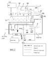
- FIG. 2 shows a preferred embodiment of the present invention. It should be clear that it represents a comprehensive example and that several features are not essential. The presence of elaborating means is implicit.
- This scheme shows a preferred way to connect the pipes of ethanol, fresh air and water among the components.
- the expander EX is connected either with the engine E crankshaft and also with an electric generator G.
- a burner B adapted to introduce fresh air and/or fuel (main fuel, fresh ethanol, degraded ethanol) into the exhaust stream in order to increase the exhaust gasses temperature.
- a super-heater SH connected with the WHR ethanol circuit through bypass-means, namely pipes and valves V4 and V4'.
- the super-heater SH When the super-heater SH is active, it represents the last heater for the ethanol steam before to be introduced into the expander EX.
- the main exchanger HE also called evaporator, being responsible to the evaporation of the ethanol.
- the main exchanger He is arranged before or after the ATS components, while the burner is optional.
- a valve, not shown is interposed in the EGR branch in order to adjust the EGR percentage.
- the EGR flow is injected into the engine intake upstream of an air filter not shown. Furthermore, the EGR can be refreshed through a cooler that exploits as cooling fluid the WHR ethanol. Thus the EGR cooler (not shown) can works as pre-heater for the WHR ethanol.
- the cooling circuit of the cooling engine comprises a heat exchanger PH immediately downstream of the combustion engine E.
- This exchanger represents another possible pre-heater for the WHR ethanol.
- the WHR circuit comprises, in succession according to the WHR ethanol circulation:
- upstream of the pump P1 is connected the fresh tank ETH-T and downstream if the pump P1 connected the withdrawing pipe D-ETH.
- FIG. 1 in order to simplify the comprehension of the connections exploits four line types.
- the continuous thick line is implemented to indicate the cooling water.
- the cooling water circuit comprises, in succession according to a possible cooling water circulation:
- figure 2 shows another cooling water circulation, where downstream of the pump P a portion of the water circulates through the engine and in parallel another portion through the charge air cooler CAC, then both the braches pass through pre-heater, depicted as a single component, then the convey together to the engine coolant cooler ECC.
- a valve BPV can be interposed in the cooling circuit in order to exclude (bypass) or include the eventual pre-heaters (PH) from being fed of warn cooling water.
- such additional tank could contain fresh Ethanol, namely non-degraded "Ethanol based working medium".
- such additional tank could contain non-degraded pure Ethanol and a second additional smaller tank contains suitable additives to be mixed with the pure non-degraded Ethanol before its introduction into the WHR circuit.
- This invention can be implemented advantageously in a computer program comprising program code means for performing one or more steps of such method, when such program is run on a computer.
- the patent shall also cover such computer program and the computer-readable medium that comprises a recorded message, such computer-readable medium comprising the program code means for performing one or more steps of such method, when such program is run on a computer.
Landscapes
- Engineering & Computer Science (AREA)
- Chemical & Material Sciences (AREA)
- Combustion & Propulsion (AREA)
- Mechanical Engineering (AREA)
- General Engineering & Computer Science (AREA)
- Output Control And Ontrol Of Special Type Engine (AREA)
Abstract
Description
- The present invention relates to the field of the combustion engines provided with system capable to recover energy from the exhaust gasses in order to produce electrical and/or to supplement the combustion engine through a thermodynamic cycle.
- The Waste heat recovery systems are well known since a long time in the combustion engine field in order to increase the overall efficiency of the combustion engine.
- One of the most valid cycles implemented to recovery energy is the Rankine cycle, usually adopting ethanol, water and refrigerants as working medium.
- Several works have been published discussing on the ideal working medium.
- Ethanol represents a good compromise between the use of water and refrigerants, the first being more economic and safe, the second being more efficient but less ecologic. All the simulations/tests account for the various critical temperatures and latent heat of vaporization. Then the efficiencies are evaluated.
- Ethanol implementation is limited to 250°C due to consequent thermal degradation that requires the replacement of the ethanol with time consumption operations.
- The pure Ethanol (pure ethyl alcohol) degrades by decomposing into ethylene and water and other components occurs at ca. 500°C. The publication "REACTIONS OF ETHYL ALCOHOL" HERBERT E. MORRIS - Department of Chemistry, University of Alberta, Edmonton, Canada (Received September 10, 1991) represents a useful source in order to understand the behavior of Ethanol in respect of temperature decomposition.
- However, several additives are added in order to preserve the WHR from corrosion or other unwanted effects. Therefore, the additivated Ethanol cannot be implemented before 250°C +/- 10°C. However the problem, substantially, does not change in case new additives would permit to improve such limit of a few degrees.
- Therefore, in view of the presence of additives, the present description, referring simply to "Ethanol", refers to a "Ethanol based working medium" in view of such mandatory presence of additives.
- The main object of the present invention is to increase the thermodynamic efficiency of a waste heat recovery system implementing ethanol as working medium, associated to a combustion engine.
- The main principle of the invention is to permit the increasing of the highest working temperature of the ethanol, beyond the Ethanol based critical temperature, by reusing the thermal degraded ethanol as combustion engine fuel, while an additional ethanol tank is introduced for refilling the waste heat recovery circuit, by restoring a needed amount of working medium for the functioning of the waste heat recovery system (WHR).
- Such additional tank could contain fresh Ethanol, namely non-degraded "Ethanol based working medium".
- Alternatively, such additional tank could contain non-degraded pure Ethanol and a second additional smaller tank contains suitable additives to be mixed with the pure non-degraded Ethanol before its introduction into the WHR circuit.
- Increasing the highest temperature of thermodynamic cycle implies an overall higher efficiency.
- According to a preferred embodiment of the present invention, the ethanol is continuously or intermittently withdrawn from the WHR circuit and injected in the cylinders of a combustion engine associated with the WHR, while fresh ethanol is withdrawn from said fresh ethanol tank and introduced into the WHR circuit.
- According to another preferred embodiment of the invention, the degraded ethanol withdrawn by the WRH and replaced by fresh one, is collected into a degraded ethanol tank and successively introduced into the engine cylinders.
- In this latter case, the injection of the degraded ethanol can be postponed according to a fuel supply strategy.
- According to another aspect of the invention the system, combustion engine and WHR, can be provided with a burner in order to increase the exhaust gas temperature, that, in turn, contribute to the WHR efficiency. The burner is provided with fresh air and eventually with fuel. This fuel can coincide with the degraded ethanol from the WHR and/or fresh ethanol from the fresh ethanol tank and/or another different fuel.
- One first object of the invention is a combustion engine provided with an ethanol Waste Heat Recovery System according to
claim 1. - Another object of the invention is a method for improving an overall efficiency of a combustion engine provided with an ethanol Waste Heat Recovery System.
- These and further objects are achieved by means of the attached claims, which describe preferred embodiment of the invention, forming an integral part of the present description.
- The invention will become fully clear from the following detailed description, given by way of a mere exemplifying and non limiting example, to be read with reference to the attached drawing figures, wherein:
-
Fig. 1 shows a sketch of concept of the present invention, -
Fig. 2 shows a detailed scheme for implementing a preferred embodiment of the present invention. - The same reference numerals and letters in the figures designate the same or functionally equivalent parts.
- According to the present invention, the term "second element" does not imply the presence of a "first element", first, second, etc... are used only for improving the clarity of the description and they should not be interpreted in a limiting way.
-
Figure 1 shows a scheme reproducing the basic concept of the present invention. - A combustion engine E, for example a six cylinder combustion engine, is preferably provided with a turbocharger T,C, with the turbine T connected to the exhaust manifold of the combustion engine and its compressor C connected to the intake manifold of the combustion engine to compress fresh air from the outside.
- The combustion engine comprises injection means EJ, adapted to supply fuel into the combustion engine cylinders and an aftertreatment system ATS to eliminate or reduce the pollutants contained in the exhaust gasses before their delivery to the environment.
- On the exhaust line, preferably upstream of the ATS or between devices DOC, SCR, DPF, etc.. of the ATS, acronyms well known to the skilled person in the art, is arranged a main heat exchanger HE capable of extracting heat from the exhaust gas to heat the working medium of a waste heat recovery system WHR to produce steam.
- In case the combustion engine is provided with turbocharger, such heat exchanger is arranged downstream of the turbine T.
- The heat recuperated by the main heat exchanger HE is, then, converted into mechanical energy ME through an expander EX, per se known.
- According to the invention, a tank containing fresh ethanol ETH-T is connected to a first point of the ethanol circuit of the WHR, while another point of the ethanol circuit of the WHR is connected with the injection means EJ through the pipe line D-ETH.
- A first control valve V1 is interposed between the WHR circuit and the fresh ethanol tank ETH-T and a second control valve V2 is interposed between the WHR circuit and the injection means EJ.
- Elaborating means CPU control, at least, said control valves V1 and V2 in order to replace degraded ethanol with fresh ethanol, through the opening of such valves V1, V2.
- Preferably, the WHR system, after the condenser CD is provided with a pump P2 for pumping the ethanol towards the exchanger(s) and then towards the steam generator HE, etc.. Preferably, said first point is between the condenser and the pump P2 and said second point is immediately downstream the pump P2. Therefore, said CPU is also adapted to control the pump.
- It should be understood that according to an embodiment of the invention, such valves V1 and V2 can be avoided, so that the WHR ethanol is continuously replaced with fresh one, according to the combustion engine fuel consumption.
- The WHR system implementing a Rankine thermodynamic cycle, that in generally per se known, is modified, according the present invention, to heat the ethanol beyond the critical temperature of about 250°C or in general beyond the critical temperature of the Ethanol based medium adopted, depending on the additives added.
- This means that the main heat exchanger HE can be suitably designed to recover a higher energy fraction with respect to known schemes and/or that further exchangers can be implemented in order to pre-heat the ethanol, for example to recover also heat from EGR gasses, and/or that further heating means can be implemented, such as a burner arranged just upstream of the main heat exchanger HE, namely between the turbine T and the main exchanger.
- Alternatively, or in combination with a redesign of the exchangers, the protection-valve, usually adopted to by-pass the exchanger(s) when the ethanol is approaching 250°C can be adjusted/controlled to operate such WHR at a temperature beyond said 250°C.
- Said elaborating means CPU, can be suitably adapted to account for the ethanol temperatures reached within the WHR, in order to estimate the thermal degradation of the same and control said valve V1, V2 to operate said replacement of the degraded ethanol with fresh one.
- In case said CPU is adapted to control the by-pass valves (V4) of the WHR exchangers, the WHR highest temperature can be also controlled accounting for a residual amount of fresh ethanol stored in the fresh ethanol tank ETH-T. In this way, in case the fresh ethanol tank is at least near to be empty, the WHR exchanger(s) is controlled in order to slow down the ethanol degradation.
- Therefore, a possible WHR ethanol temperature control can be realized as a function of the residual fresh ethanol contained into the Ethanol tank ETH-T.
- In case the combustion engine is an Otto-cycle engine, the ethanol could represent the fuel burned into the combustion engine; therefore, the fresh ethanol tank ETH-T is also connected directly with the injection means EJ through a direct supply line EFL. This means that the combustion engine is called to burn fresh ethanol added with degraded ethanol coming from the WHR.
- Preferably, a valve V3 is arranged on the supply line EFL in order to better manage the fresh contribution and the degraded contribution of ethanol. This means that the valves V1 - V3 are, preferably, all subject of reciprocally coherent control.
- Alternatively, the combustion engine even being an Otto-cycle could be supplied with gasoline or it could be a Diesel-cycle supplied with diesel fuel. In these cases, the vehicle can be provided with an additional fuel tank FUEL directly connected with the injection means EJ. Therefore, the degraded ethanol coming from the WHR and/or the fresh ethanol coming directly from the Ethanol tank is added to the main fuel that is respectively gasoline or diesel.
- A further valve can be arranged on the pipe line connecting the injection means EJ and the fuel tank FUEL.
- The adoption of bio-fuel is well known, however, according to a preferred embodiment of the present invention, the pre-mixing of gasoline or diesel with degraded/fresh ethanol to obtain a bio-fuel is controlled and executed onboard of the vehicle.
- Even when the Fuel tank contains a main fuel such as gasoline or diesel, the pipe EFL connecting the fresh ethanol tank with the injection means EJ can be present, preferably with its own valve V3, in those cases where the addition of ethanol to the main fuel is controlled regardless of the degradation rate of ethanol implemented into the WHR system of the invention, operating beyond the critical temperature of 250°C.
- The degradation of the ethanol is strictly related to the highest temperature reached within the WHR system. Therefore, when the degradation is really low the valves V1 and V2 are intermittently or slightly opened (not necessarily at the same time) after hundreds of working hours of the WHR. On the contrary, when the degradation is really fast, the ethanol replacement can be continuous.
- According to a preferred embodiment of the invention, that can be combined either with an intermittent or a continuous replacement of degraded ethanol, the degraded ethanol withdrawn from the WHR can be first collected into a degraded ethanol tank D-ETH-T arranged between said second valve V2 and said injection means EJ on said degraded ethanol pipe line D-ETH.
- The implementation of this degraded ethanol tank can be really useful, even not essential, in order to perform the addition of ethanol to the main fuel according to predetermined engine supply strategies.
- According to another preferred embodiment of the invention, that can be combined with the above discussed embodiments, the degraded and/or fresh ethanol can be injected into the combustion engine cylinder not previously mixed with the main fuel, but according to a RCCI combustion engine principle.
- RCCI uses in-cylinder fuel blending with at least two fuels of different reactivity and multiple injections to control in-cylinder fuel reactivity to optimize combustion phasing, duration and magnitude. The process involves introduction of a low reactivity fuel into the cylinder to create a well-mixed charge of low reactivity fuel, air and recirculated exhaust gases. The high reactivity fuel is injected before ignition of the premixed fuel occurs using single or multiple injections directly into the combustion chamber. Examples of fuel pairings for RCCI are gasoline and diesel mixtures, ethanol and diesel, and gasoline and gasoline with small additions of a cetane-number booster (di-tert-butyl peroxide (DTBP)).
- Therefore, the present invention finds a really favorable context if implemented in one RCCI scheme.
- The mechanical energy produced by the Expander EX can be exploited to produce electrical energy and/or can be directed to the combustion engine crankshaft, in order to supplement the combustion engine in a "compound" fashion. However, any way to exploit such mechanical energy can be implemented.
- The elaborating means CPU discussed above, according to a preferred embodiment of the present invention implementing said RCCI strategy can be adapted to control such degraded and main fuel injection into the combustion engine cylinder and the replacing of the ethanol used as working medium into the WHR system associated with said combustion engine.
- Preferably, such elaborating means coincide with the engine control unit ECU usually implemented to control the combustion engine operation.
-
Figure 2 shows a preferred embodiment of the present invention. It should be clear that it represents a comprehensive example and that several features are not essential. The presence of elaborating means is implicit. - This scheme, in addition with respect the previous figure, shows a preferred way to connect the pipes of ethanol, fresh air and water among the components.
- It should be noted that, according to
figure 2 , the expander EX is connected either with the engine E crankshaft and also with an electric generator G. - In addition, preferably, immediately downstream of the turbine T is arranged a burner B adapted to introduce fresh air and/or fuel (main fuel, fresh ethanol, degraded ethanol) into the exhaust stream in order to increase the exhaust gasses temperature.
- Immediately downstream of the burner B is arranged a super-heater SH, connected with the WHR ethanol circuit through bypass-means, namely pipes and valves V4 and V4'.
- When the super-heater SH is active, it represents the last heater for the ethanol steam before to be introduced into the expander EX.
- Immediately downstream of the super-heater SH is arranged at least one of the ATS components, listed above, and then the main exchanger HE also called evaporator, being responsible to the evaporation of the ethanol.
- It should be understood that, in case the super-heater is not present, then the main exchanger He is arranged before or after the ATS components, while the burner is optional.
- The exhaust gasses, after passing the ATS, regardless whether the last component crossed is an ATS component or the main exchanger HE, can be recirculated according to an EGR strategy. Preferably, a valve, not shown is interposed in the EGR branch in order to adjust the EGR percentage.
- According to a preferred embodiment of the invention, the EGR flow is injected into the engine intake upstream of an air filter not shown. Furthermore, the EGR can be refreshed through a cooler that exploits as cooling fluid the WHR ethanol. Thus the EGR cooler (not shown) can works as pre-heater for the WHR ethanol.
- According to
figure 2 , the cooling circuit of the cooling engine comprises a heat exchanger PH immediately downstream of the combustion engine E. This exchanger represents another possible pre-heater for the WHR ethanol. - After these considerations, the WHR circuit comprises, in succession according to the WHR ethanol circulation:
- ethanol Pump P1,
- (optional) pre-heaters,
- main heater HE,
- (optional) super-heater SH,
- Expander EX,
- Condenser CD.
- As discussed above, preferably upstream of the pump P1 is connected the fresh tank ETH-T and downstream if the pump P1 connected the withdrawing pipe D-ETH.
-
Figure 2 , in order to simplify the comprehension of the connections exploits four line types. The continuous thick line is implemented to indicate the cooling water. The cooling water circuit comprises, in succession according to a possible cooling water circulation: - water pump P,
- charge air cooler CAC to refresh charge directed to the combustion engine,
- the combustion engine E,
- (optional) WHR ethanol pre-heater PH,
- (optional) EGR exchanger defining another WHR ethanol pre-heater,
- Engine coolant cooler ECC.
- The preferred embodiment of
figure 2 shows another cooling water circulation, where downstream of the pump P a portion of the water circulates through the engine and in parallel another portion through the charge air cooler CAC, then both the braches pass through pre-heater, depicted as a single component, then the convey together to the engine coolant cooler ECC. - About the per se known features of the WHR and of the WHR in combination with the combustion engine, we herewith recall everything disclosed in
EP1674681 of the same author, and in particular, the adoption of an intake filter and the connection of the EGR pipe upstream with respect to said intake filter. - A valve BPV can be interposed in the cooling circuit in order to exclude (bypass) or include the eventual pre-heaters (PH) from being fed of warn cooling water.
- As disclosed above, such additional tank could contain fresh Ethanol, namely non-degraded "Ethanol based working medium".
- Alternatively, such additional tank could contain non-degraded pure Ethanol and a second additional smaller tank contains suitable additives to be mixed with the pure non-degraded Ethanol before its introduction into the WHR circuit.
- This invention can be implemented advantageously in a computer program comprising program code means for performing one or more steps of such method, when such program is run on a computer. For this reason, the patent shall also cover such computer program and the computer-readable medium that comprises a recorded message, such computer-readable medium comprising the program code means for performing one or more steps of such method, when such program is run on a computer.
- Many changes, modifications, variations and other uses and applications of the subject invention will become apparent to those skilled in the art after considering the specification and the accompanying drawings which disclose preferred embodiments thereof. All such changes, modifications, variations and other uses and applications which do not depart from the scope of the invention are deemed to be covered by this invention.
- It should be understood that all the single features and/or embodiments can be combined between each other. In addition, the features disclosed in the prior art background should are introduced only in order to better understand the invention and not as a declaration about the existence of known prior art. Therefore, also the features described in the prior art background can be considered in combination with those mentioned in each embodiment of the detailed description.
- Further implementation details will not be described, as the man skilled in the art is able to carry out the invention starting from the teaching of the above description.
Claims (15)
- Combustion engine (E) provided with a Waste Heat Recovery System (WHR) draining thermal energy from an exhaust pipe (EP) of the combustion engine (E) in order to produce mechanical energy (ME) by exploiting ethanol or ethanol based as working medium, wherein the combustion engine comprises injection means (EJ) to supply the combustion engine with a fuel, and wherein the WHR comprises a fresh ethanol tank (ETH-T) connected with a first point of a WHR circuit and a pipe connection (D-ETH) connecting a second point of the WHR circuit with said injection means (EJ) in order to supply the combustion engine with ethanol from the WHR circuit and to replace the WHR circuit ethanol with fresh one.
- Combustion engine according to claim 1, further comprising control means (CPU, V1, V2) adapted to perform at least one of the following steps:- adjusting a highest temperature of the ethanol of the WHR, even beyond a predefined critical temperature of ethanol or ethanol based medium,- estimation of a thermal degradation of the ethanol (or ethanol based medium) of the WHR according to highest temperature reached within the WHR,- adjusting the replacement of the degraded ethanol of the WHR circuit with fresh ethanol.
- Combustion engine according to claim 2, wherein said adjusting the replacing of the ethanol of the WHR circuit with fresh ethanol is function of said estimation of a thermal degradation of the ethanol of the WHR circuit.
- Combustion engine according to any of the previous claims, further comprising a separate fuel tank (FUEL), for storing a different fuel with respect to ethanol, connected with said injection means, wherein said injection means are adapted to mix such different fuel with said ethanol from the WHR in order to supply said combustion engine (E) with bio-fuel.
- Combustion engine according to any of the previous claims from 1 to 3, further comprising a separate fuel tank (FUEL), for storing a different fuel with respect to ethanol, connected with said injection means and wherein said fresh ethanol tank (ETH-T) is also connected with said injection means (EJ) directly through a dedicated pipe line (EFL), and wherein said injection means are adapted to mix such different fuel with said ethanol from the WHR and/or form the fresh ethanol tank (ETH-T) in order to supply said combustion engine (E) with bio-fuel.
- Combustion engine according to any of previous claim 4 or 5, wherein said bio-fuel is obtained before its injection into the combustion engine or said bio-fuel is obtained according to a RCCI strategy.
- Combustion engine according to any of previous claims from 1 to 6, wherein said engine exhaust pipe (EP) further comprises a burner (B) suitable to increase exhaust gasses temperature, wherein the burner is provided with fresh air and at least one among fresh ethanol, ethanol from WHR, another fuel different from ethanol.
- Method for improving an overall efficiency of a combustion engine provided with an ethanol Waste Heat Recovery System (WHR), the method comprising the following steps:- setting the WHR so that the highest temperature exceed a predetermined ethanol or ethanol based critical temperature,- replacing the WHR degraded ethanol with fresh one,- introducing the degraded ethanol coming from WHR circuit into the combustion engine cylinders.
- Method according to claim 8, further comprising- estimation of a thermal degradation of the ethanol of the WHR according to highest temperature reached within the WHR,- adjusting the replacing of the ethanol of the WHR with fresh ethanol.
- Method according to one of the previous claims 8 or 9, further comprising a step of controlling the WHR highest temperature though bypass means and/or though a burner (B) arranged on an exhaust pipe (EP) of the combustion engine.
- Method according to claim 10, further comprising a step of controlling an injection of fuel within said burner (B).
- Method according to claim 11, wherein said fuel injected into the burner is degraded ethanol from the WHR and/or fresh ethanol and/or another fuel different form ethanol (or ethanol based medium).
- Computer program comprising computer program code means adapted to perform all the steps of any of the claims 8 to 12, when said program is run on a computer.
- A computer readable medium having a program recorded thereon, said computer readable medium comprising computer program code means adapted to perform all the steps of any of the claim 8 to 12, when said program is run on a computer.
- Vehicle comprising the combustion engine provided with a Waste Heat Recovery System (WHR) draining thermal energy from an exhaust pipe (EP) of the combustion engine (E) in order to produce mechanical energy (ME) and exploiting ethanol as working medium, according to any of the claims from 1 to 7.
Priority Applications (2)
| Application Number | Priority Date | Filing Date | Title |
|---|---|---|---|
| ES15155849T ES2802287T3 (en) | 2015-02-19 | 2015-02-19 | Combustion engine equipped with a residual heat recovery system |
| EP15155849.1A EP3059429B1 (en) | 2015-02-19 | 2015-02-19 | Combustion engine provided with a waste heat recovery system |
Applications Claiming Priority (1)
| Application Number | Priority Date | Filing Date | Title |
|---|---|---|---|
| EP15155849.1A EP3059429B1 (en) | 2015-02-19 | 2015-02-19 | Combustion engine provided with a waste heat recovery system |
Publications (2)
| Publication Number | Publication Date |
|---|---|
| EP3059429A1 true EP3059429A1 (en) | 2016-08-24 |
| EP3059429B1 EP3059429B1 (en) | 2020-04-22 |
Family
ID=52477708
Family Applications (1)
| Application Number | Title | Priority Date | Filing Date |
|---|---|---|---|
| EP15155849.1A Active EP3059429B1 (en) | 2015-02-19 | 2015-02-19 | Combustion engine provided with a waste heat recovery system |
Country Status (2)
| Country | Link |
|---|---|
| EP (1) | EP3059429B1 (en) |
| ES (1) | ES2802287T3 (en) |
Citations (8)
| Publication number | Priority date | Publication date | Assignee | Title |
|---|---|---|---|---|
| WO2000047874A1 (en) * | 1999-02-11 | 2000-08-17 | Bp Amoco Corporation | Method of generating power using an advanced thermochemical recuperation cycle |
| EP1674681A2 (en) | 2004-12-27 | 2006-06-28 | Iveco Motorenforschung AG | Method for adjusting the temperature of an exhaust gas treatment system for internal combustion engines and engine apparatus |
| DE102009039551A1 (en) * | 2009-09-01 | 2011-03-03 | Andreas Gotter | Alcohol-fueled combustion engine of an otto engine comprises a charging device, in which exhaust gas is led towards exhaust-gas catalyst over a heat exchanger, which is flowed through with the alcohol fuel as process medium |
| WO2012027688A1 (en) * | 2010-08-26 | 2012-03-01 | Modine Manufacturing Company | Waste heat recovery system and method of operating the same |
| DE102011117054A1 (en) * | 2011-10-27 | 2012-05-03 | Daimler Ag | Device for energy recovery from waste heat flow of internal combustion engine in vehicle, comprises working medium-circuit, in which Clausius-Rankine circulation process is carried out |
| EP2495422A2 (en) * | 2011-03-03 | 2012-09-05 | Behr GmbH & Co. KG | Combustion engine |
| DE102012221153A1 (en) * | 2012-11-20 | 2014-06-05 | Robert Bosch Gmbh | Method for monitoring system for recovering energy from waste heat stream of self-activating combustion engine, involves arranging fluid circuit in current flow path, measuring and validating property of fluid circuit during operation |
| US20150013328A1 (en) * | 2013-07-09 | 2015-01-15 | Volkswagen Aktiengesellschaft | Drive unit for a motor vehicle |
-
2015
- 2015-02-19 EP EP15155849.1A patent/EP3059429B1/en active Active
- 2015-02-19 ES ES15155849T patent/ES2802287T3/en active Active
Patent Citations (8)
| Publication number | Priority date | Publication date | Assignee | Title |
|---|---|---|---|---|
| WO2000047874A1 (en) * | 1999-02-11 | 2000-08-17 | Bp Amoco Corporation | Method of generating power using an advanced thermochemical recuperation cycle |
| EP1674681A2 (en) | 2004-12-27 | 2006-06-28 | Iveco Motorenforschung AG | Method for adjusting the temperature of an exhaust gas treatment system for internal combustion engines and engine apparatus |
| DE102009039551A1 (en) * | 2009-09-01 | 2011-03-03 | Andreas Gotter | Alcohol-fueled combustion engine of an otto engine comprises a charging device, in which exhaust gas is led towards exhaust-gas catalyst over a heat exchanger, which is flowed through with the alcohol fuel as process medium |
| WO2012027688A1 (en) * | 2010-08-26 | 2012-03-01 | Modine Manufacturing Company | Waste heat recovery system and method of operating the same |
| EP2495422A2 (en) * | 2011-03-03 | 2012-09-05 | Behr GmbH & Co. KG | Combustion engine |
| DE102011117054A1 (en) * | 2011-10-27 | 2012-05-03 | Daimler Ag | Device for energy recovery from waste heat flow of internal combustion engine in vehicle, comprises working medium-circuit, in which Clausius-Rankine circulation process is carried out |
| DE102012221153A1 (en) * | 2012-11-20 | 2014-06-05 | Robert Bosch Gmbh | Method for monitoring system for recovering energy from waste heat stream of self-activating combustion engine, involves arranging fluid circuit in current flow path, measuring and validating property of fluid circuit during operation |
| US20150013328A1 (en) * | 2013-07-09 | 2015-01-15 | Volkswagen Aktiengesellschaft | Drive unit for a motor vehicle |
Non-Patent Citations (1)
| Title |
|---|
| HERBERT E. MORRIS, REACTIONS OF ETHYL ALCOHOL, 10 September 1991 (1991-09-10) |
Also Published As
| Publication number | Publication date |
|---|---|
| EP3059429B1 (en) | 2020-04-22 |
| ES2802287T3 (en) | 2021-01-18 |
Similar Documents
| Publication | Publication Date | Title |
|---|---|---|
| EP3064734B1 (en) | Engine cooling system | |
| EP2565436A1 (en) | Ammonia-burning internal combustion engine | |
| US8602007B2 (en) | Integrated exhaust gas recirculation and charge cooling system | |
| US11635039B1 (en) | Work vehicle alcohol-based power system with on-board ether | |
| CN106168161A (en) | A kind of explosive motor and the method controlling this explosive motor | |
| CN103080523B (en) | Engine equipment including heat recovery circuits and exhaust aftertreatment systems | |
| Furukawa et al. | A study of the rankine cycle generating system for heavy duty HV Trucks | |
| CN103003532B (en) | Engine arrangement comprising a heat recovery circuit | |
| JP2013199882A (en) | Internal combustion engine | |
| CN102305151A (en) | System for efficiently recovering waste heat energy from internal combustion engine | |
| US20190234343A1 (en) | Organic rankine cycle waste heat recovery system having two loops | |
| US20170051634A1 (en) | Vehicle heat recovery system | |
| EP3059430B1 (en) | Combustion engine provided with a waste heat recovery system | |
| EP3059429B1 (en) | Combustion engine provided with a waste heat recovery system | |
| JP2010242726A (en) | Waste heat recovery device | |
| Boretti | Improving the efficiency of turbocharged spark ignition engines for passenger cars through waste heat recovery | |
| CN209976660U (en) | Waste heat recovery system of EGR engine | |
| EP2789811B1 (en) | System for heat recovery of a combustion engine | |
| CN203769899U (en) | Automobile engine waste heat utilization system | |
| US10815929B2 (en) | Systems and methods for waste heat recovery for internal combustion engines | |
| CN102661194A (en) | Engine exhaust gas energy recovery system | |
| US20230250751A1 (en) | A Mono-Block Reciprocating Piston Composite ICE/ORC Power Plant | |
| JP2018062910A (en) | Cooling system for egr cooler | |
| CN120830552A (en) | Internal combustion engine waste heat recovery method and system | |
| EP3379067A1 (en) | Engine system |
Legal Events
| Date | Code | Title | Description |
|---|---|---|---|
| PUAI | Public reference made under article 153(3) epc to a published international application that has entered the european phase |
Free format text: ORIGINAL CODE: 0009012 |
|
| AK | Designated contracting states |
Kind code of ref document: A1 Designated state(s): AL AT BE BG CH CY CZ DE DK EE ES FI FR GB GR HR HU IE IS IT LI LT LU LV MC MK MT NL NO PL PT RO RS SE SI SK SM TR |
|
| AX | Request for extension of the european patent |
Extension state: BA ME |
|
| STAA | Information on the status of an ep patent application or granted ep patent |
Free format text: STATUS: REQUEST FOR EXAMINATION WAS MADE |
|
| 17P | Request for examination filed |
Effective date: 20170131 |
|
| RBV | Designated contracting states (corrected) |
Designated state(s): AL AT BE BG CH CY CZ DE DK EE ES FI FR GB GR HR HU IE IS IT LI LT LU LV MC MK MT NL NO PL PT RO RS SE SI SK SM TR |
|
| STAA | Information on the status of an ep patent application or granted ep patent |
Free format text: STATUS: EXAMINATION IS IN PROGRESS |
|
| 17Q | First examination report despatched |
Effective date: 20190410 |
|
| GRAP | Despatch of communication of intention to grant a patent |
Free format text: ORIGINAL CODE: EPIDOSNIGR1 |
|
| STAA | Information on the status of an ep patent application or granted ep patent |
Free format text: STATUS: GRANT OF PATENT IS INTENDED |
|
| INTG | Intention to grant announced |
Effective date: 20191118 |
|
| GRAS | Grant fee paid |
Free format text: ORIGINAL CODE: EPIDOSNIGR3 |
|
| GRAA | (expected) grant |
Free format text: ORIGINAL CODE: 0009210 |
|
| STAA | Information on the status of an ep patent application or granted ep patent |
Free format text: STATUS: THE PATENT HAS BEEN GRANTED |
|
| AK | Designated contracting states |
Kind code of ref document: B1 Designated state(s): AL AT BE BG CH CY CZ DE DK EE ES FI FR GB GR HR HU IE IS IT LI LT LU LV MC MK MT NL NO PL PT RO RS SE SI SK SM TR |
|
| REG | Reference to a national code |
Ref country code: CH Ref legal event code: EP |
|
| REG | Reference to a national code |
Ref country code: IE Ref legal event code: FG4D |
|
| REG | Reference to a national code |
Ref country code: DE Ref legal event code: R096 Ref document number: 602015050978 Country of ref document: DE |
|
| REG | Reference to a national code |
Ref country code: AT Ref legal event code: REF Ref document number: 1260402 Country of ref document: AT Kind code of ref document: T Effective date: 20200515 |
|
| REG | Reference to a national code |
Ref country code: LT Ref legal event code: MG4D |
|
| REG | Reference to a national code |
Ref country code: NL Ref legal event code: MP Effective date: 20200422 |
|
| PG25 | Lapsed in a contracting state [announced via postgrant information from national office to epo] |
Ref country code: FI Free format text: LAPSE BECAUSE OF FAILURE TO SUBMIT A TRANSLATION OF THE DESCRIPTION OR TO PAY THE FEE WITHIN THE PRESCRIBED TIME-LIMIT Effective date: 20200422 Ref country code: SE Free format text: LAPSE BECAUSE OF FAILURE TO SUBMIT A TRANSLATION OF THE DESCRIPTION OR TO PAY THE FEE WITHIN THE PRESCRIBED TIME-LIMIT Effective date: 20200422 Ref country code: PT Free format text: LAPSE BECAUSE OF FAILURE TO SUBMIT A TRANSLATION OF THE DESCRIPTION OR TO PAY THE FEE WITHIN THE PRESCRIBED TIME-LIMIT Effective date: 20200824 Ref country code: NL Free format text: LAPSE BECAUSE OF FAILURE TO SUBMIT A TRANSLATION OF THE DESCRIPTION OR TO PAY THE FEE WITHIN THE PRESCRIBED TIME-LIMIT Effective date: 20200422 Ref country code: LT Free format text: LAPSE BECAUSE OF FAILURE TO SUBMIT A TRANSLATION OF THE DESCRIPTION OR TO PAY THE FEE WITHIN THE PRESCRIBED TIME-LIMIT Effective date: 20200422 Ref country code: GR Free format text: LAPSE BECAUSE OF FAILURE TO SUBMIT A TRANSLATION OF THE DESCRIPTION OR TO PAY THE FEE WITHIN THE PRESCRIBED TIME-LIMIT Effective date: 20200723 Ref country code: IS Free format text: LAPSE BECAUSE OF FAILURE TO SUBMIT A TRANSLATION OF THE DESCRIPTION OR TO PAY THE FEE WITHIN THE PRESCRIBED TIME-LIMIT Effective date: 20200822 Ref country code: NO Free format text: LAPSE BECAUSE OF FAILURE TO SUBMIT A TRANSLATION OF THE DESCRIPTION OR TO PAY THE FEE WITHIN THE PRESCRIBED TIME-LIMIT Effective date: 20200722 |
|
| REG | Reference to a national code |
Ref country code: AT Ref legal event code: MK05 Ref document number: 1260402 Country of ref document: AT Kind code of ref document: T Effective date: 20200422 |
|
| PG25 | Lapsed in a contracting state [announced via postgrant information from national office to epo] |
Ref country code: RS Free format text: LAPSE BECAUSE OF FAILURE TO SUBMIT A TRANSLATION OF THE DESCRIPTION OR TO PAY THE FEE WITHIN THE PRESCRIBED TIME-LIMIT Effective date: 20200422 Ref country code: LV Free format text: LAPSE BECAUSE OF FAILURE TO SUBMIT A TRANSLATION OF THE DESCRIPTION OR TO PAY THE FEE WITHIN THE PRESCRIBED TIME-LIMIT Effective date: 20200422 Ref country code: HR Free format text: LAPSE BECAUSE OF FAILURE TO SUBMIT A TRANSLATION OF THE DESCRIPTION OR TO PAY THE FEE WITHIN THE PRESCRIBED TIME-LIMIT Effective date: 20200422 Ref country code: BG Free format text: LAPSE BECAUSE OF FAILURE TO SUBMIT A TRANSLATION OF THE DESCRIPTION OR TO PAY THE FEE WITHIN THE PRESCRIBED TIME-LIMIT Effective date: 20200722 |
|
| PG25 | Lapsed in a contracting state [announced via postgrant information from national office to epo] |
Ref country code: AL Free format text: LAPSE BECAUSE OF FAILURE TO SUBMIT A TRANSLATION OF THE DESCRIPTION OR TO PAY THE FEE WITHIN THE PRESCRIBED TIME-LIMIT Effective date: 20200422 |
|
| REG | Reference to a national code |
Ref country code: ES Ref legal event code: FG2A Ref document number: 2802287 Country of ref document: ES Kind code of ref document: T3 Effective date: 20210118 |
|
| REG | Reference to a national code |
Ref country code: DE Ref legal event code: R097 Ref document number: 602015050978 Country of ref document: DE |
|
| PG25 | Lapsed in a contracting state [announced via postgrant information from national office to epo] |
Ref country code: SM Free format text: LAPSE BECAUSE OF FAILURE TO SUBMIT A TRANSLATION OF THE DESCRIPTION OR TO PAY THE FEE WITHIN THE PRESCRIBED TIME-LIMIT Effective date: 20200422 Ref country code: EE Free format text: LAPSE BECAUSE OF FAILURE TO SUBMIT A TRANSLATION OF THE DESCRIPTION OR TO PAY THE FEE WITHIN THE PRESCRIBED TIME-LIMIT Effective date: 20200422 Ref country code: CZ Free format text: LAPSE BECAUSE OF FAILURE TO SUBMIT A TRANSLATION OF THE DESCRIPTION OR TO PAY THE FEE WITHIN THE PRESCRIBED TIME-LIMIT Effective date: 20200422 Ref country code: RO Free format text: LAPSE BECAUSE OF FAILURE TO SUBMIT A TRANSLATION OF THE DESCRIPTION OR TO PAY THE FEE WITHIN THE PRESCRIBED TIME-LIMIT Effective date: 20200422 Ref country code: DK Free format text: LAPSE BECAUSE OF FAILURE TO SUBMIT A TRANSLATION OF THE DESCRIPTION OR TO PAY THE FEE WITHIN THE PRESCRIBED TIME-LIMIT Effective date: 20200422 Ref country code: AT Free format text: LAPSE BECAUSE OF FAILURE TO SUBMIT A TRANSLATION OF THE DESCRIPTION OR TO PAY THE FEE WITHIN THE PRESCRIBED TIME-LIMIT Effective date: 20200422 |
|
| PG25 | Lapsed in a contracting state [announced via postgrant information from national office to epo] |
Ref country code: PL Free format text: LAPSE BECAUSE OF FAILURE TO SUBMIT A TRANSLATION OF THE DESCRIPTION OR TO PAY THE FEE WITHIN THE PRESCRIBED TIME-LIMIT Effective date: 20200422 Ref country code: SK Free format text: LAPSE BECAUSE OF FAILURE TO SUBMIT A TRANSLATION OF THE DESCRIPTION OR TO PAY THE FEE WITHIN THE PRESCRIBED TIME-LIMIT Effective date: 20200422 |
|
| PLBE | No opposition filed within time limit |
Free format text: ORIGINAL CODE: 0009261 |
|
| STAA | Information on the status of an ep patent application or granted ep patent |
Free format text: STATUS: NO OPPOSITION FILED WITHIN TIME LIMIT |
|
| 26N | No opposition filed |
Effective date: 20210125 |
|
| PG25 | Lapsed in a contracting state [announced via postgrant information from national office to epo] |
Ref country code: SI Free format text: LAPSE BECAUSE OF FAILURE TO SUBMIT A TRANSLATION OF THE DESCRIPTION OR TO PAY THE FEE WITHIN THE PRESCRIBED TIME-LIMIT Effective date: 20200422 |
|
| PG25 | Lapsed in a contracting state [announced via postgrant information from national office to epo] |
Ref country code: MC Free format text: LAPSE BECAUSE OF FAILURE TO SUBMIT A TRANSLATION OF THE DESCRIPTION OR TO PAY THE FEE WITHIN THE PRESCRIBED TIME-LIMIT Effective date: 20200422 |
|
| REG | Reference to a national code |
Ref country code: BE Ref legal event code: MM Effective date: 20210228 |
|
| PG25 | Lapsed in a contracting state [announced via postgrant information from national office to epo] |
Ref country code: LI Free format text: LAPSE BECAUSE OF NON-PAYMENT OF DUE FEES Effective date: 20210228 Ref country code: LU Free format text: LAPSE BECAUSE OF NON-PAYMENT OF DUE FEES Effective date: 20210219 Ref country code: CH Free format text: LAPSE BECAUSE OF NON-PAYMENT OF DUE FEES Effective date: 20210228 |
|
| PG25 | Lapsed in a contracting state [announced via postgrant information from national office to epo] |
Ref country code: IE Free format text: LAPSE BECAUSE OF NON-PAYMENT OF DUE FEES Effective date: 20210219 |
|
| PG25 | Lapsed in a contracting state [announced via postgrant information from national office to epo] |
Ref country code: BE Free format text: LAPSE BECAUSE OF NON-PAYMENT OF DUE FEES Effective date: 20210228 |
|
| PG25 | Lapsed in a contracting state [announced via postgrant information from national office to epo] |
Ref country code: HU Free format text: LAPSE BECAUSE OF FAILURE TO SUBMIT A TRANSLATION OF THE DESCRIPTION OR TO PAY THE FEE WITHIN THE PRESCRIBED TIME-LIMIT; INVALID AB INITIO Effective date: 20150219 |
|
| P01 | Opt-out of the competence of the unified patent court (upc) registered |
Effective date: 20230519 |
|
| PG25 | Lapsed in a contracting state [announced via postgrant information from national office to epo] |
Ref country code: CY Free format text: LAPSE BECAUSE OF FAILURE TO SUBMIT A TRANSLATION OF THE DESCRIPTION OR TO PAY THE FEE WITHIN THE PRESCRIBED TIME-LIMIT Effective date: 20200422 |
|
| PG25 | Lapsed in a contracting state [announced via postgrant information from national office to epo] |
Ref country code: MK Free format text: LAPSE BECAUSE OF FAILURE TO SUBMIT A TRANSLATION OF THE DESCRIPTION OR TO PAY THE FEE WITHIN THE PRESCRIBED TIME-LIMIT Effective date: 20200422 |
|
| PG25 | Lapsed in a contracting state [announced via postgrant information from national office to epo] |
Ref country code: TR Free format text: LAPSE BECAUSE OF FAILURE TO SUBMIT A TRANSLATION OF THE DESCRIPTION OR TO PAY THE FEE WITHIN THE PRESCRIBED TIME-LIMIT Effective date: 20200422 |
|
| PG25 | Lapsed in a contracting state [announced via postgrant information from national office to epo] |
Ref country code: MT Free format text: LAPSE BECAUSE OF FAILURE TO SUBMIT A TRANSLATION OF THE DESCRIPTION OR TO PAY THE FEE WITHIN THE PRESCRIBED TIME-LIMIT Effective date: 20200422 |
|
| PGFP | Annual fee paid to national office [announced via postgrant information from national office to epo] |
Ref country code: GB Payment date: 20260223 Year of fee payment: 12 |
|
| PGFP | Annual fee paid to national office [announced via postgrant information from national office to epo] |
Ref country code: ES Payment date: 20260317 Year of fee payment: 12 |
|
| PGFP | Annual fee paid to national office [announced via postgrant information from national office to epo] |
Ref country code: DE Payment date: 20260220 Year of fee payment: 12 |
|
| PGFP | Annual fee paid to national office [announced via postgrant information from national office to epo] |
Ref country code: IT Payment date: 20260209 Year of fee payment: 12 |
|
| PGFP | Annual fee paid to national office [announced via postgrant information from national office to epo] |
Ref country code: FR Payment date: 20260227 Year of fee payment: 12 |