EP3059396A1 - Gas turbine engine and turbine configurations - Google Patents
Gas turbine engine and turbine configurations Download PDFInfo
- Publication number
- EP3059396A1 EP3059396A1 EP16156375.4A EP16156375A EP3059396A1 EP 3059396 A1 EP3059396 A1 EP 3059396A1 EP 16156375 A EP16156375 A EP 16156375A EP 3059396 A1 EP3059396 A1 EP 3059396A1
- Authority
- EP
- European Patent Office
- Prior art keywords
- platform
- diameter platform
- outer diameter
- vane assembly
- turbine
- Prior art date
- Legal status (The legal status is an assumption and is not a legal conclusion. Google has not performed a legal analysis and makes no representation as to the accuracy of the status listed.)
- Granted
Links
Images


Classifications
-
- F—MECHANICAL ENGINEERING; LIGHTING; HEATING; WEAPONS; BLASTING
- F01—MACHINES OR ENGINES IN GENERAL; ENGINE PLANTS IN GENERAL; STEAM ENGINES
- F01D—NON-POSITIVE DISPLACEMENT MACHINES OR ENGINES, e.g. STEAM TURBINES
- F01D9/00—Stators
- F01D9/02—Nozzles; Nozzle boxes; Stator blades; Guide conduits, e.g. individual nozzles
- F01D9/04—Nozzles; Nozzle boxes; Stator blades; Guide conduits, e.g. individual nozzles forming ring or sector
- F01D9/041—Nozzles; Nozzle boxes; Stator blades; Guide conduits, e.g. individual nozzles forming ring or sector using blades
-
- F—MECHANICAL ENGINEERING; LIGHTING; HEATING; WEAPONS; BLASTING
- F01—MACHINES OR ENGINES IN GENERAL; ENGINE PLANTS IN GENERAL; STEAM ENGINES
- F01D—NON-POSITIVE DISPLACEMENT MACHINES OR ENGINES, e.g. STEAM TURBINES
- F01D9/00—Stators
- F01D9/02—Nozzles; Nozzle boxes; Stator blades; Guide conduits, e.g. individual nozzles
- F01D9/023—Transition ducts between combustor cans and first stage of the turbine in gas-turbine engines; their cooling or sealings
-
- F—MECHANICAL ENGINEERING; LIGHTING; HEATING; WEAPONS; BLASTING
- F01—MACHINES OR ENGINES IN GENERAL; ENGINE PLANTS IN GENERAL; STEAM ENGINES
- F01D—NON-POSITIVE DISPLACEMENT MACHINES OR ENGINES, e.g. STEAM TURBINES
- F01D9/00—Stators
- F01D9/02—Nozzles; Nozzle boxes; Stator blades; Guide conduits, e.g. individual nozzles
- F01D9/04—Nozzles; Nozzle boxes; Stator blades; Guide conduits, e.g. individual nozzles forming ring or sector
- F01D9/042—Nozzles; Nozzle boxes; Stator blades; Guide conduits, e.g. individual nozzles forming ring or sector fixing blades to stators
-
- F—MECHANICAL ENGINEERING; LIGHTING; HEATING; WEAPONS; BLASTING
- F02—COMBUSTION ENGINES; HOT-GAS OR COMBUSTION-PRODUCT ENGINE PLANTS
- F02C—GAS-TURBINE PLANTS; AIR INTAKES FOR JET-PROPULSION PLANTS; CONTROLLING FUEL SUPPLY IN AIR-BREATHING JET-PROPULSION PLANTS
- F02C3/00—Gas-turbine plants characterised by the use of combustion products as the working fluid
- F02C3/14—Gas-turbine plants characterised by the use of combustion products as the working fluid characterised by the arrangement of the combustion chamber in the plant
-
- F—MECHANICAL ENGINEERING; LIGHTING; HEATING; WEAPONS; BLASTING
- F05—INDEXING SCHEMES RELATING TO ENGINES OR PUMPS IN VARIOUS SUBCLASSES OF CLASSES F01-F04
- F05D—INDEXING SCHEME FOR ASPECTS RELATING TO NON-POSITIVE-DISPLACEMENT MACHINES OR ENGINES, GAS-TURBINES OR JET-PROPULSION PLANTS
- F05D2220/00—Application
- F05D2220/30—Application in turbines
- F05D2220/32—Application in turbines in gas turbines
-
- F—MECHANICAL ENGINEERING; LIGHTING; HEATING; WEAPONS; BLASTING
- F05—INDEXING SCHEMES RELATING TO ENGINES OR PUMPS IN VARIOUS SUBCLASSES OF CLASSES F01-F04
- F05D—INDEXING SCHEME FOR ASPECTS RELATING TO NON-POSITIVE-DISPLACEMENT MACHINES OR ENGINES, GAS-TURBINES OR JET-PROPULSION PLANTS
- F05D2240/00—Components
- F05D2240/10—Stators
- F05D2240/12—Fluid guiding means, e.g. vanes
-
- F—MECHANICAL ENGINEERING; LIGHTING; HEATING; WEAPONS; BLASTING
- F05—INDEXING SCHEMES RELATING TO ENGINES OR PUMPS IN VARIOUS SUBCLASSES OF CLASSES F01-F04
- F05D—INDEXING SCHEME FOR ASPECTS RELATING TO NON-POSITIVE-DISPLACEMENT MACHINES OR ENGINES, GAS-TURBINES OR JET-PROPULSION PLANTS
- F05D2240/00—Components
- F05D2240/10—Stators
- F05D2240/12—Fluid guiding means, e.g. vanes
- F05D2240/128—Nozzles
-
- F—MECHANICAL ENGINEERING; LIGHTING; HEATING; WEAPONS; BLASTING
- F05—INDEXING SCHEMES RELATING TO ENGINES OR PUMPS IN VARIOUS SUBCLASSES OF CLASSES F01-F04
- F05D—INDEXING SCHEME FOR ASPECTS RELATING TO NON-POSITIVE-DISPLACEMENT MACHINES OR ENGINES, GAS-TURBINES OR JET-PROPULSION PLANTS
- F05D2240/00—Components
- F05D2240/35—Combustors or associated equipment
-
- F—MECHANICAL ENGINEERING; LIGHTING; HEATING; WEAPONS; BLASTING
- F05—INDEXING SCHEMES RELATING TO ENGINES OR PUMPS IN VARIOUS SUBCLASSES OF CLASSES F01-F04
- F05D—INDEXING SCHEME FOR ASPECTS RELATING TO NON-POSITIVE-DISPLACEMENT MACHINES OR ENGINES, GAS-TURBINES OR JET-PROPULSION PLANTS
- F05D2240/00—Components
- F05D2240/80—Platforms for stationary or moving blades
-
- F—MECHANICAL ENGINEERING; LIGHTING; HEATING; WEAPONS; BLASTING
- F05—INDEXING SCHEMES RELATING TO ENGINES OR PUMPS IN VARIOUS SUBCLASSES OF CLASSES F01-F04
- F05D—INDEXING SCHEME FOR ASPECTS RELATING TO NON-POSITIVE-DISPLACEMENT MACHINES OR ENGINES, GAS-TURBINES OR JET-PROPULSION PLANTS
- F05D2260/00—Function
- F05D2260/20—Heat transfer, e.g. cooling
Definitions
- the present disclosure relates to gas turbine engines and, in particular, to turbine assemblies and turbine interface configurations for gas turbine engines.
- Gas turbine engines are required to operate efficiently during operation and flight. These engines create a tremendous amount of force and generate high levels of heat. As such, components of these engines are subjected to high levels of stress, temperature and pressure. It is necessary to provide components that can withstand the demands of a gas turbine engine. It is also desirable to provide components with increased operating longevity.
- Some components of a gas turbine engine experience growth due to the high temperature environment of the engine.
- hot section components of an engine may undergo transformations is size during operation.
- Uneven temperature distributions across engine parts can reduce the fatigue resistance, operation performance and/or operational life of a component. Accordingly, there is a desire to provide configurations that reduce temperature disparities and overcomes one or more of the aforementioned drawbacks.
- the vane assembly includes a plurality of turbine vanes, an inner diameter platform coupled to the base portion of each of the plurality of turbine vanes, wherein the leading edge of the inner diameter platform is associated with a first axis, and an outer diameter platform coupled to the top portion of each of the plurality of turbine vanes.
- the leading edge of the outer diameter platform is associated with a second axis, the second axis offset from the first axis such that the outer platform extends away from the leading edge of the turbine blades a distance greater than an amount the inner platform extends away from the leading edge of the turbine blades.
- the plurality of turbine blades are configured for a high lift/low foil count high pressure turbine vane assembly.
- a platform length of the outer diameter is greater than 18% of vane pitch.
- the plurality of turbine vanes radially extend between the inner diameter platform and outer diameter platform.
- the outer diameter platform is a circumferentially extending annular structure wherein leading edges of the inner and outer platforms are configured to define, at least in part, an interface between the vane assembly and a combustor.
- the outer diameter platform extends 0.5 inches longer than the inner diameter platform.
- the outer diameter platform extends longer than the inner diameter platform with a range of 0.1 inches longer to 1 inch longer.
- the outer diameter platform is configured to evenly distribute temperature across the outer diameter platform.
- the inner diameter platform and outer diameter platform each extend from the leading edge such that each platform length is at least 18% of vane pitch relative to a respective platform radius.
- the gas turbine engine includes a combustor extending along a portion of a gas turbine engine and a turbine vane assembly configured to interface with the combustor.
- the turbine vane assembly includes a plurality of turbine vanes, an inner diameter platform coupled to the base portion of each of the plurality of turbine vanes, wherein the leading edge of the inner diameter platform is associated with a first axis, and an outer diameter platform coupled to the top portion of each of the plurality of turbine vanes.
- the leading edge of the outer diameter platform is associated with a second axis, the second axis offset from the first axis such that the outer platform extends away from the leading edge of the turbine blades a distance greater than an amount the inner platform extends away from the leading edge of the turbine blades.
- the inner diameter platform and outer diameter platform interface with the combustor.
- the plurality of turbine blades are configured for a high lift/low foil count high pressure turbine vane assembly.
- a platform length of the outer diameter is greater than 18% of vane pitch.
- the plurality of turbine vanes radially extend between the inner diameter platform and outer diameter platform.
- the outer diameter platform is a circumferentially extending annular structure wherein leading edges of the inner and outer platforms are configured to define, at least in part, an interface between the vane assembly and a combustor.
- the outer diameter platform extends 0.5 inches longer than the inner diameter platform.
- the outer diameter platform extends longer than the inner diameter platform with a range of 0.1 inches longer to 1 inch longer.
- the outer diameter platform is configured to evenly distribute temperature across the outer diameter platform.
- the inner diameter platform and outer diameter platform each extend from the leading edge such that each platform length is at least 18% of vane pitch relative to a respective platform radius.
- the inner diameter platform and outer diameter platform are located immediately downstream of the combustor.
- an interface between the vane assembly and the combustor includes a gas-path passage between a cavity of the combustor and leading edge of the vanes.
- a high pressure turbine vane assembly for a gas turbine engine, the vane assembly comprising: a plurality of turbine vanes; an inner diameter platform coupled to the base portion of each of the plurality of turbine vanes, wherein the leading edge of the inner diameter platform is associated with a first axis; and an outer diameter platform coupled to the top portion of each of the plurality of turbine vanes, wherein the leading edge of the outer diameter platform is associated with a second axis, the second axis offset from the first axis such that the outer platform extends away from the leading edge of the turbine vanes a distance greater than an amount the inner platform extends away from the leading edge of the turbine vanes.
- the plurality of turbine vanes are configured for a high lift/low foil count high pressure turbine vane assembly.
- a platform length of the outer diameter is greater than 18% of vane pitch.
- the plurality of turbine vanes radially extend between the inner diameter platform and outer diameter platform.
- the outer diameter platform is a circumferentially extending annular structure wherein leading edges of the inner and outer platforms are configured to define, at least in part, an interface between the vane assembly and a combustor.
- the outer diameter platform extends 0.5 inches longer than the inner diameter platform.
- the outer diameter platform extends longer than the inner diameter platform with a range of 0.1 inches longer to 1 inch longer.
- the outer diameter platform is configured to evenly distribute temperature across the outer diameter platform.
- the inner diameter platform and outer diameter platform each extend from the leading edge such that each platform length is at least 18% of vane pitch relative to a respective platform radius.
- a gas turbine engine having combustor and turbine interface configuration
- the gas turbine engine comprising: a combustor extending along a portion of a gas turbine engine; and a turbine vane assembly configured to interface with the combustor, the turbine vane assembly including a plurality of turbine vanes, an inner diameter platform coupled to the base portion of each of the plurality of turbine vanes, wherein the leading edge of the inner diameter platform is associated with a first axis, and an outer diameter platform coupled to the top portion of each of the plurality of turbine vanes, wherein the leading edge of the outer diameter platform is associated with a second axis, the second axis offset from the first axis such that the outer platform extends away from the leading edge of the turbine vanes a distance greater than an amount the inner platform extends away from the leading edge of the turbine vanes, and wherein the inner diameter platform and outer diameter platform interface with the combustor.
- the plurality of turbine vanes are configured for a high lift/low foil count high pressure turbine vane assembly.
- a platform length of the outer diameter is greater than 18% of vane pitch.
- the plurality of turbine vanes radially extend between the inner diameter platform and outer diameter platform.
- the outer diameter platform is a circumferentially extending annular structure wherein leading edges of the inner and outer platforms are configured to define, at least in part, an interface between the vane assembly and a combustor.
- the outer diameter platform extends 0.5 inches longer than the inner diameter platform.
- the outer diameter platform extends longer than the inner diameter platform with a range of 0.1 inches longer to 1 inch longer.
- the outer diameter platform is configured to evenly distribute temperature across the outer diameter platform.
- the inner diameter platform and outer diameter platform each extend from the leading edge such that each platform length is at least 18% of vane pitch relative to a respective platform radius.
- the inner diameter platform and outer diameter platform are located immediately downstream of the combustor.
- an interface between the vane assembly and the combustor includes a gas-path passage between a cavity of the combustor and leading edge of the vanes.
- a vane assembly and a configuration for a vane assembly are provided.
- the vane assembly may be configured to allow for an even temperature distribution base one or more features of the assembly including but not limited to than outer diameter platform of the vane assemble.
- a vane assembly includes an outer diameter platform that extends beyond the inner diameter platform of the vane assembly, in a forward direction towards a combustor.
- the configuration of an outer diameter platform can affect the temperature distribution across the vane assembly to allow for an even temperature distribution. By providing an even temperature distribution, component life and/or operational efficiency may be increased.
- the terms “a” or “an” shall mean one or more than one.
- the term “plurality” shall mean two or more than two.
- the term “another” is defined as a second or more.
- the terms “including” and/or “having” are open ended (e.g., comprising).
- the term “or” as used herein is to be interpreted as inclusive or meaning any one or any combination. Therefore, “A, B or C” means “any of the following: A; B; C; A and B; A and C; B and C; A, B and C". An exception to this definition will occur only when a combination of elements, functions, steps or acts are in some way inherently mutually exclusive.
- FIG. 1 depicts a cross-sectional representation of a gas turbine engine according to one or more embodiments.
- Gas turbine engine 100 includes combustor 105 and vane assembly 110.
- Combustor 105 extends along a portion of a gas turbine engine 100 and provides a gas-flow path from combustor cavity 106 to vane assembly 110.
- Vane assembly 110 may be a high pressure turbine vane assembly down stream from combustor 105.
- Vane assembly 110 interfaces with combustor 105 such that the interface between the vane assembly 110 and combustor 105 includes a gas-path passage between a cavity 106 of the combustor and leading edge of vanes of vane assembly 110.
- vane assembly 110 may include a plurality of turbine vanes, such as vane 111.
- the leading edge of vane 111 is shown as 115.
- Vane assembly 110 includes inner diameter platform 112 coupled to the base portion of each vane of vane assembly 110.
- the leading edge 116 of inner diameter platform 112 is associated with a first axis 125.
- Outer diameter platform 113 coupled to the top portion of each vane, wherein the leading edge 114 of the outer diameter platfom 113 is associated with a second axis 120.
- Outer diameter platform 113 is a circumferentially extending annular structure wherein leading edges of the inner and outer platforms 113, 112 are configured to define, at least in part, an interface 117 between the vane assembly 110 and combustor 105.
- Second axis 120 is offset from first axis 125 such that the outer platform 113 extends away from the leading edge 115 of turbine vane 111, and the other vanes of vane assembly 110, a distance 130 greater than an amount the inner platform 112 extends away from the leading edge 115 of turbine 111.
- First axis 125 and second axis 120 are reference lines that may be tangential or perpendicular to the axis of rotation of the turbine 111.
- Inner diameter platform 112 and outer diameter platform 113 are configured to interface with combustor 105.
- interface 117 relates to the intersection of cavity region 107 and vane assembly 110.
- Outer diameter platform 113 is configured to evenly distribute temperature across the outer diameter platform associated with the interface 117.
- outer diameter platform 113 extends 0.5 inches longer (i.e., longer in an axial direction towards the front of the engine which translates towards the left side of the image in FIG. 1 ) than the inner diameter platform 112.
- Outer diameter platform 113 extends longer than the inner diameter platform 112 within a range of 0.1 inches longer to 1 inch.
- Distance 130 may be provided for length of the outer diameter platform 113 that is greater than 18% of vane 111 pitch.
- vane pitch relates to a ratio of circumference to the number airfoils.
- vane pitch is calculated using the outer diameter of the vane platform at the vane leading edge with respect to a radius of the platform.
- vane pitch is calculated using the inner diameter of the vane platform at the vane leading edge with respect to a radius of the platform.
- FIG. 2 depicts a graphical representation of a combustor and vane assembly of a gas turbine engine according to one or more embodiments.
- Combustor 200 is shown as an annular combustor having outer diameter portion 205 and inner diameter portion 206.
- Combustor 200 interfaces with vane assembly 210 include a plurality of vanes, such as vane 215.
- vane assembly 210 is the first stage of a high pressure turbine.
- Vane 215 includes leading edge 216 and trailing edge 217.
- Vane 215 is fit between outer diameter platform 220 and inner diameter platform 225.
- interface 230 An interface between combustor 200 interfaces with vane assembly 210 is shown as 230.
- interface 230 is configured to allow for outer diameter platform 220 to extend further than inner diameter platform 225 towards combustor 200. As such, the temperature distribution in the interface may be evenly distributed.
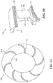
- FIGs. 3A-3B depict a vane assembly according to one or more embodiments.
- FIG. 3A depicts a view of vane assembly 300 according to one or more embodiments.
- vane assembly 300 includes one or more vanes, such as vane 305, an inner diameter platform 315 and outer diameter platform 310.
- Vane assembly 300 may be a high pressure turbine vane assembly.
- a plurality of turbine vanes of vane assembly 300 are configured for a high lift/low foil count turbine vane assembly.
- a high lift/low foil count turbine vane assembly can relate to a vane assembly of a high pressure turbine assembly aft of the combustor.
- the plurality of turbine vanes radially extend between the inner diameter platform 315 and outer diameter platform 310.
- FIG. 3B depicts a partial representation, shown as 320, of vane assembly 300 for two vanes of the assembly.
- Vane 305 is shown including leading edge 321 and trailing edge 322.
- diameter platform 310 extends beyond the leading edge of vane 305 as shown by 325.
- Region 325 relates to a combustor vane assembly interface region.
Landscapes
- Engineering & Computer Science (AREA)
- Mechanical Engineering (AREA)
- General Engineering & Computer Science (AREA)
- Chemical & Material Sciences (AREA)
- Combustion & Propulsion (AREA)
- Turbine Rotor Nozzle Sealing (AREA)
Abstract
Description
- The present disclosure relates to gas turbine engines and, in particular, to turbine assemblies and turbine interface configurations for gas turbine engines.
- Gas turbine engines are required to operate efficiently during operation and flight. These engines create a tremendous amount of force and generate high levels of heat. As such, components of these engines are subjected to high levels of stress, temperature and pressure. It is necessary to provide components that can withstand the demands of a gas turbine engine. It is also desirable to provide components with increased operating longevity.
- Some components of a gas turbine engine experience growth due to the high temperature environment of the engine. By way of example, hot section components of an engine may undergo transformations is size during operation. Uneven temperature distributions across engine parts can reduce the fatigue resistance, operation performance and/or operational life of a component. Accordingly, there is a desire to provide configurations that reduce temperature disparities and overcomes one or more of the aforementioned drawbacks. There is also a desire to improve the configuration of gas turbine engines and vane assemblies.
- Disclosed and claimed herein are gas turbine engines and high pressure turbine vane assemblies for gas turbine engines. One embodiment is directed to a high pressure turbine vane assembly for a gas turbine engine. The vane assembly includes a plurality of turbine vanes, an inner diameter platform coupled to the base portion of each of the plurality of turbine vanes, wherein the leading edge of the inner diameter platform is associated with a first axis, and an outer diameter platform coupled to the top portion of each of the plurality of turbine vanes. The leading edge of the outer diameter platform is associated with a second axis, the second axis offset from the first axis such that the outer platform extends away from the leading edge of the turbine blades a distance greater than an amount the inner platform extends away from the leading edge of the turbine blades.
- In one embodiment, the plurality of turbine blades are configured for a high lift/low foil count high pressure turbine vane assembly.
- In one embodiment, a platform length of the outer diameter is greater than 18% of vane pitch.
- In one embodiment, the plurality of turbine vanes radially extend between the inner diameter platform and outer diameter platform.
- In one embodiment, the outer diameter platform is a circumferentially extending annular structure wherein leading edges of the inner and outer platforms are configured to define, at least in part, an interface between the vane assembly and a combustor.
- In one embodiment, the outer diameter platform extends 0.5 inches longer than the inner diameter platform.
- In one embodiment, the outer diameter platform extends longer than the inner diameter platform with a range of 0.1 inches longer to 1 inch longer.
- In one embodiment, the outer diameter platform is configured to evenly distribute temperature across the outer diameter platform.
- In one embodiment, the inner diameter platform and outer diameter platform each extend from the leading edge such that each platform length is at least 18% of vane pitch relative to a respective platform radius.
- Another embodiment is directed to a gas turbine engine having combustor and turbine interface configuration. The gas turbine engine includes a combustor extending along a portion of a gas turbine engine and a turbine vane assembly configured to interface with the combustor. The turbine vane assembly includes a plurality of turbine vanes, an inner diameter platform coupled to the base portion of each of the plurality of turbine vanes, wherein the leading edge of the inner diameter platform is associated with a first axis, and an outer diameter platform coupled to the top portion of each of the plurality of turbine vanes. The leading edge of the outer diameter platform is associated with a second axis, the second axis offset from the first axis such that the outer platform extends away from the leading edge of the turbine blades a distance greater than an amount the inner platform extends away from the leading edge of the turbine blades. The inner diameter platform and outer diameter platform interface with the combustor.
- In one embodiment, the plurality of turbine blades are configured for a high lift/low foil count high pressure turbine vane assembly.
- In one embodiment, a platform length of the outer diameter is greater than 18% of vane pitch.
- In one embodiment, the plurality of turbine vanes radially extend between the inner diameter platform and outer diameter platform.
- In one embodiment, the outer diameter platform is a circumferentially extending annular structure wherein leading edges of the inner and outer platforms are configured to define, at least in part, an interface between the vane assembly and a combustor.
- In one embodiment, the outer diameter platform extends 0.5 inches longer than the inner diameter platform.
- In one embodiment, the outer diameter platform extends longer than the inner diameter platform with a range of 0.1 inches longer to 1 inch longer.
- In one embodiment, the outer diameter platform is configured to evenly distribute temperature across the outer diameter platform.
- In one embodiment, the inner diameter platform and outer diameter platform each extend from the leading edge such that each platform length is at least 18% of vane pitch relative to a respective platform radius.
- In one embodiment, the inner diameter platform and outer diameter platform are located immediately downstream of the combustor.
- In one embodiment, an interface between the vane assembly and the combustor includes a gas-path passage between a cavity of the combustor and leading edge of the vanes.
- According to one embodiment, there is provided a high pressure turbine vane assembly for a gas turbine engine, the vane assembly comprising: a plurality of turbine vanes; an inner diameter platform coupled to the base portion of each of the plurality of turbine vanes, wherein the leading edge of the inner diameter platform is associated with a first axis; and an outer diameter platform coupled to the top portion of each of the plurality of turbine vanes, wherein the leading edge of the outer diameter platform is associated with a second axis, the second axis offset from the first axis such that the outer platform extends away from the leading edge of the turbine vanes a distance greater than an amount the inner platform extends away from the leading edge of the turbine vanes.
- In addition to one or more of the features described above, or as an alternative to any of the foregoing embodiments, the plurality of turbine vanes are configured for a high lift/low foil count high pressure turbine vane assembly.
- In addition to one or more of the features described above, or as an alternative to any of the foregoing embodiments, a platform length of the outer diameter is greater than 18% of vane pitch.
- In addition to one or more of the features described above, or as an alternative to any of the foregoing embodiments, the plurality of turbine vanes radially extend between the inner diameter platform and outer diameter platform.
- In addition to one or more of the features described above, or as an alternative to any of the foregoing embodiments, the outer diameter platform is a circumferentially extending annular structure wherein leading edges of the inner and outer platforms are configured to define, at least in part, an interface between the vane assembly and a combustor.
- In addition to one or more of the features described above, or as an alternative to any of the foregoing embodiments, the outer diameter platform extends 0.5 inches longer than the inner diameter platform.
- In addition to one or more of the features described above, or as an alternative to any of the foregoing embodiments, the outer diameter platform extends longer than the inner diameter platform with a range of 0.1 inches longer to 1 inch longer.
- In addition to one or more of the features described above, or as an alternative to any of the foregoing embodiments, the outer diameter platform is configured to evenly distribute temperature across the outer diameter platform.
- In addition to one or more of the features described above, or as an alternative to any of the foregoing embodiments, the inner diameter platform and outer diameter platform each extend from the leading edge such that each platform length is at least 18% of vane pitch relative to a respective platform radius.
- According to another embodiment there is provided a gas turbine engine having combustor and turbine interface configuration, the gas turbine engine comprising: a combustor extending along a portion of a gas turbine engine; and a turbine vane assembly configured to interface with the combustor, the turbine vane assembly including a plurality of turbine vanes, an inner diameter platform coupled to the base portion of each of the plurality of turbine vanes, wherein the leading edge of the inner diameter platform is associated with a first axis, and an outer diameter platform coupled to the top portion of each of the plurality of turbine vanes, wherein the leading edge of the outer diameter platform is associated with a second axis, the second axis offset from the first axis such that the outer platform extends away from the leading edge of the turbine vanes a distance greater than an amount the inner platform extends away from the leading edge of the turbine vanes, and wherein the inner diameter platform and outer diameter platform interface with the combustor.
- In addition to one or more of the features described above, or as an alternative to any of the foregoing embodiments, the plurality of turbine vanes are configured for a high lift/low foil count high pressure turbine vane assembly.
- In addition to one or more of the features described above, or as an alternative to any of the foregoing embodiments, a platform length of the outer diameter is greater than 18% of vane pitch.
- In addition to one or more of the features described above, or as an alternative to any of the foregoing embodiments, the plurality of turbine vanes radially extend between the inner diameter platform and outer diameter platform.
- In addition to one or more of the features described above, or as an alternative to any of the foregoing embodiments, the outer diameter platform is a circumferentially extending annular structure wherein leading edges of the inner and outer platforms are configured to define, at least in part, an interface between the vane assembly and a combustor.
- In addition to one or more of the features described above, or as an alternative to any of the foregoing embodiments, the outer diameter platform extends 0.5 inches longer than the inner diameter platform.
- In addition to one or more of the features described above, or as an alternative to any of the foregoing embodiments, the outer diameter platform extends longer than the inner diameter platform with a range of 0.1 inches longer to 1 inch longer.
- In addition to one or more of the features described above, or as an alternative to any of the foregoing embodiments, the outer diameter platform is configured to evenly distribute temperature across the outer diameter platform.
- In addition to one or more of the features described above, or as an alternative to any of the foregoing embodiments, the inner diameter platform and outer diameter platform each extend from the leading edge such that each platform length is at least 18% of vane pitch relative to a respective platform radius.
- In addition to one or more of the features described above, or as an alternative to any of the foregoing embodiments, the inner diameter platform and outer diameter platform are located immediately downstream of the combustor.
- In addition to one or more of the features described above, or as an alternative to any of the foregoing embodiments, an interface between the vane assembly and the combustor includes a gas-path passage between a cavity of the combustor and leading edge of the vanes.
- The features, objects, and advantages of the present disclosure will become more apparent from the detailed description set forth below when taken in conjunction with the drawings in which like reference characters identify correspondingly throughout and wherein:
-
FIG. 1 depicts a cross-sectional representation of a gas turbine engine according to one or more embodiments; -
FIG. 2 depicts a graphical representation of a combustor and vane assembly of a gas turbine engine according to one or more embodiments; -
FIGs. 3A-3B depict a vane assembly according to one or more embodiments; and - One aspect of this disclosure relates to configurations for a gas turbine and in particular combustor and vane interface. According to one embodiment a vane assembly and a configuration for a vane assembly are provided. The vane assembly may be configured to allow for an even temperature distribution base one or more features of the assembly including but not limited to than outer diameter platform of the vane assemble. In one embodiment, a vane assembly includes an outer diameter platform that extends beyond the inner diameter platform of the vane assembly, in a forward direction towards a combustor. As will be discussed herein, the configuration of an outer diameter platform can affect the temperature distribution across the vane assembly to allow for an even temperature distribution. By providing an even temperature distribution, component life and/or operational efficiency may be increased.
- As used herein, the terms "a" or "an" shall mean one or more than one. The term "plurality" shall mean two or more than two. The term "another" is defined as a second or more. The terms "including" and/or "having" are open ended (e.g., comprising). The term "or" as used herein is to be interpreted as inclusive or meaning any one or any combination. Therefore, "A, B or C" means "any of the following: A; B; C; A and B; A and C; B and C; A, B and C". An exception to this definition will occur only when a combination of elements, functions, steps or acts are in some way inherently mutually exclusive.
- Reference throughout this document to "one embodiment," "certain embodiments," "an embodiment," or similar term means that a particular feature, structure, or characteristic described in connection with the embodiment is included in at least one embodiment. Thus, the appearances of such phrases in various places throughout this specification are not necessarily all referring to the same embodiment. Furthermore, the particular features, structures, or characteristics may be combined in any suitable manner on one or more embodiments without limitation.
- Referring now to the figures,
FIG. 1 depicts a cross-sectional representation of a gas turbine engine according to one or more embodiments.Gas turbine engine 100 includescombustor 105 andvane assembly 110.Combustor 105 extends along a portion of agas turbine engine 100 and provides a gas-flow path fromcombustor cavity 106 tovane assembly 110.Vane assembly 110 may be a high pressure turbine vane assembly down stream fromcombustor 105.Vane assembly 110 interfaces withcombustor 105 such that the interface between thevane assembly 110 andcombustor 105 includes a gas-path passage between acavity 106 of the combustor and leading edge of vanes ofvane assembly 110. - According to one embodiment,
vane assembly 110 may include a plurality of turbine vanes, such asvane 111. The leading edge ofvane 111 is shown as 115.Vane assembly 110 includesinner diameter platform 112 coupled to the base portion of each vane ofvane assembly 110. Theleading edge 116 ofinner diameter platform 112 is associated with afirst axis 125.Outer diameter platform 113 coupled to the top portion of each vane, wherein theleading edge 114 of theouter diameter platfom 113 is associated with asecond axis 120.Outer diameter platform 113 is a circumferentially extending annular structure wherein leading edges of the inner andouter platforms interface 117 between thevane assembly 110 andcombustor 105.Second axis 120 is offset fromfirst axis 125 such that theouter platform 113 extends away from theleading edge 115 ofturbine vane 111, and the other vanes ofvane assembly 110, adistance 130 greater than an amount theinner platform 112 extends away from theleading edge 115 ofturbine 111.First axis 125 andsecond axis 120 are reference lines that may be tangential or perpendicular to the axis of rotation of theturbine 111. -
Inner diameter platform 112 andouter diameter platform 113 are configured to interface withcombustor 105. According to one embodiment,interface 117 relates to the intersection ofcavity region 107 andvane assembly 110.Outer diameter platform 113 is configured to evenly distribute temperature across the outer diameter platform associated with theinterface 117. According to one embodiment,outer diameter platform 113 extends 0.5 inches longer (i.e., longer in an axial direction towards the front of the engine which translates towards the left side of the image inFIG. 1 ) than theinner diameter platform 112.Outer diameter platform 113 extends longer than theinner diameter platform 112 within a range of 0.1 inches longer to 1 inch.Distance 130 may be provided for length of theouter diameter platform 113 that is greater than 18% ofvane 111 pitch. According to one embodiment, vane pitch relates to a ratio of circumference to the number airfoils. Forouter diameter platform 113, vane pitch is calculated using the outer diameter of the vane platform at the vane leading edge with respect to a radius of the platform. Forinner diameter platform 112, vane pitch is calculated using the inner diameter of the vane platform at the vane leading edge with respect to a radius of the platform. -
FIG. 2 depicts a graphical representation of a combustor and vane assembly of a gas turbine engine according to one or more embodiments.Combustor 200 is shown as an annular combustor havingouter diameter portion 205 andinner diameter portion 206.Combustor 200 interfaces withvane assembly 210 include a plurality of vanes, such asvane 215. According to one embodiment,vane assembly 210 is the first stage of a high pressure turbine.Vane 215 includesleading edge 216 and trailingedge 217.Vane 215 is fit betweenouter diameter platform 220 andinner diameter platform 225. - An interface between
combustor 200 interfaces withvane assembly 210 is shown as 230. According to one embodiment,interface 230 is configured to allow forouter diameter platform 220 to extend further thaninner diameter platform 225 towardscombustor 200. As such, the temperature distribution in the interface may be evenly distributed. -
FIGs. 3A-3B depict a vane assembly according to one or more embodiments.FIG. 3A depicts a view ofvane assembly 300 according to one or more embodiments. According to one embodiment,vane assembly 300 includes one or more vanes, such asvane 305, aninner diameter platform 315 andouter diameter platform 310.Vane assembly 300 may be a high pressure turbine vane assembly. According to another embodiment, a plurality of turbine vanes ofvane assembly 300 are configured for a high lift/low foil count turbine vane assembly. As used herein, a high lift/low foil count turbine vane assembly can relate to a vane assembly of a high pressure turbine assembly aft of the combustor. The plurality of turbine vanes radially extend between theinner diameter platform 315 andouter diameter platform 310. -
FIG. 3B depicts a partial representation, shown as 320, ofvane assembly 300 for two vanes of the assembly.Vane 305 is shown including leadingedge 321 and trailingedge 322. According to one embodiment,diameter platform 310 extends beyond the leading edge ofvane 305 as shown by 325.Region 325 relates to a combustor vane assembly interface region. - While this disclosure has been particularly shown and described with references to exemplary embodiments thereof, it will be understood by those skilled in the art that various changes in form and details may be made therein without departing from the scope of the claimed embodiments.
- The following clauses set out features of the present disclosure which may or may not presently be claimed but which may form basis for future amendments and/or a divisional application.
- 1. A high pressure turbine vane assembly for a gas turbine engine, the vane assembly comprising:
- a plurality of turbine vanes;
- an inner diameter platform coupled to the base portion of each of the plurality of turbine vanes, wherein the leading edge of the inner diameter platform is associated with a first axis; and
- an outer diameter platform coupled to the top portion of each of the plurality of turbine vanes, wherein the leading edge of the outer diameter platform is associated with a second axis, the second axis offset from the first axis such that the outer platform extends away from the leading edge of the turbine vanes a distance greater than an amount the inner platform extends away from the leading edge of the turbine vanes.
- 2. The high pressure turbine vane assembly of
clause 1, wherein the plurality of turbine vanes are configured for a high lift/low foil count high pressure turbine vane assembly. - 3. The high pressure turbine vane assembly of
clause 1, wherein a platform length of the outer diameter is greater than 18% of vane pitch. - 4. The high pressure turbine vane assembly of
clause 1, wherein the plurality of turbine vanes radially extend between the inner diameter platform and outer diameter platform. - 5. The high pressure turbine vane assembly of
clause 1, wherein the outer diameter platform is a circumferentially extending annular structure wherein leading edges of the inner and outer platforms are configured to define, at least in part, an interface between the vane assembly and a combustor. - 6. The high pressure turbine vane assembly of
clause 1, wherein the outer diameter platform extends 0.5 inches longer than the inner diameter platform. - 7. The high pressure turbine vane assembly of
clause 1, wherein the outer diameter platform extends longer than the inner diameter platform with a range of 0.1 inches longer to 1 inch longer. - 8. The high pressure turbine vane assembly of
clause 1, wherein the outer diameter platform is configured to evenly distribute temperature across the outer diameter platform. - 9. The high pressure turbine vane assembly of
clause 1, wherein the inner diameter platform and outer diameter platform each extend from the leading edge such that each platform length is at least 18% of vane pitch relative to a respective platform radius. - 10. A gas turbine engine having combustor and turbine interface configuration, the gas turbine engine comprising:
- a combustor extending along a portion of a gas turbine engine; and
- a turbine vane assembly configured to interface with the combustor, the turbine vane assembly including
- a plurality of turbine vanes,
- an inner diameter platform coupled to the base portion of each of the plurality of turbine vanes, wherein the leading edge of the inner diameter platform is associated with a first axis, and
- an outer diameter platform coupled to the top portion of each of the plurality of turbine vanes, wherein the leading edge of the outer diameter platform is associated with a second axis, the second axis offset from the first axis such that the outer platform extends away from the leading edge of the turbine vanes a distance greater than an amount the inner platform extends away from the leading edge of the turbine vanes, and
- wherein the inner diameter platform and outer diameter platform interface with the combustor.
- 11. The gas turbine engine of clause 10, wherein the plurality of turbine vanes are configured for a high lift/low foil count high pressure turbine vane assembly.
- 12. The gas turbine engine of clause 10, wherein a platform length of the outer diameter is greater than 18% of vane pitch.
- 13. The gas turbine engine of clause 10, wherein the plurality of turbine vanes radially extend between the inner diameter platform and outer diameter platform.
- 14. The gas turbine engine of clause 10, wherein the outer diameter platform is a circumferentially extending annular structure wherein leading edges of the inner and outer platforms are configured to define, at least in part, an interface between the vane assembly and a combustor.
- 15. The gas turbine engine of clause 10, wherein the outer diameter platform extends 0.5 inches longer than the inner diameter platform.
- 16. The gas turbine engine of clause 10, wherein the outer diameter platform extends longer than the inner diameter platform with a range of 0.1 inches longer to 1 inch longer.
- 17. The gas turbine engine of clause 10, wherein the outer diameter platform is configured to evenly distribute temperature across the outer diameter platform.
- 18. The gas turbine engine of clause 10, wherein the inner diameter platform and outer diameter platform each extend from the leading edge such that each platform length is at least 18% of vane pitch relative to a respective platform radius.
- 19. The gas turbine engine of clause 10, wherein the inner diameter platform and outer diameter platform are located immediately downstream of the combustor.
- 20. The gas turbine engine of clause 10, wherein an interface between the vane assembly and the combustor includes a gas-path passage between a cavity of the combustor and leading edge of the vanes.
Claims (12)
- A high pressure turbine vane assembly (110) for a gas turbine engine (100), the vane assembly comprising:a plurality of turbine vanes (111);an inner diameter platform (112) coupled to the base portion of each of the plurality of turbine vanes, wherein the leading edge (116) of the inner diameter platform is associated with a first axis (125); andan outer diameter platform (113) coupled to the top portion of each of the plurality of turbine vanes, wherein the leading edge (114) of the outer diameter platform is associated with a second axis (120), the second axis offset from the first axis such that the outer platform extends away from the leading edge (115) of the turbine vanes a distance greater than an amount the inner platform extends away from the leading edge of the turbine vanes.
- The high pressure turbine vane assembly (110) of claim 1, wherein the plurality of turbine vanes (111) are configured for a high lift/low foil count high pressure turbine vane assembly.
- The high pressure turbine vane assembly (110) of claims 1 or 2, wherein a platform (113) length of the outer diameter is greater than 18% of vane pitch.
- The high pressure turbine vane assembly (110) of claims 1, 2 or 3, wherein the plurality of turbine vanes (111) radially extend between the inner diameter platform (112) and outer diameter platform (113).
- The high pressure turbine vane assembly (110) of any preceding claim, wherein the outer diameter platform (113) is a circumferentially extending annular structure wherein leading edges (116, 114) of the inner and outer platforms are configured to define, at least in part, an interface (117) between the vane assembly and a combustor (105).
- The high pressure turbine vane assembly (110) of any preceding claim, wherein the outer diameter platform (113) extends 0.5 inches (13 mm) longer than the inner diameter platform (112).
- The high pressure turbine vane assembly (110) of any preceding claim, wherein the outer diameter platform (113) extends longer than the inner diameter platform (112) with a range of 0.1 inches longer to 1 inch longer (2.5 mm to 25 mm).
- The high pressure turbine vane assembly (110) of any preceding claim, wherein the outer diameter platform (113) is configured to evenly distribute temperature across the outer diameter platform.
- The high pressure turbine vane assembly (110) of any preceding claim, wherein the inner diameter platform (112) and outer diameter platform (113) each extend from the leading edge such that each platform length is at least 18% of vane pitch relative to a respective platform radius.
- A gas turbine engine having combustor (105) and turbine interface configuration, the gas turbine engine comprising:a combustor extending along a portion of a gas turbine engine; anda turbine vane assembly (110) of any preceding claim configured to interface with the combustor,and wherein the inner diameter platform (112) and outer diameter platform (113) interface with the combustor.
- The gas turbine engine of claim 10, wherein the inner diameter platform (112) and outer diameter platform (113) are located immediately downstream of the combustor (105).
- The gas turbine engine of claims 10 or 11, wherein an interface (117) between the vane assembly (110) and the combustor (105) includes a gas-path passage between a cavity (106) of the combustor and leading edge (115) of the vanes (111).
Applications Claiming Priority (1)
| Application Number | Priority Date | Filing Date | Title |
|---|---|---|---|
| US14/626,371 US20160245104A1 (en) | 2015-02-19 | 2015-02-19 | Gas turbine engine and turbine configurations |
Publications (2)
| Publication Number | Publication Date |
|---|---|
| EP3059396A1 true EP3059396A1 (en) | 2016-08-24 |
| EP3059396B1 EP3059396B1 (en) | 2021-03-31 |
Family
ID=55398235
Family Applications (1)
| Application Number | Title | Priority Date | Filing Date |
|---|---|---|---|
| EP16156375.4A Active EP3059396B1 (en) | 2015-02-19 | 2016-02-18 | Gas turbine engine and turbine configurations |
Country Status (2)
| Country | Link |
|---|---|
| US (1) | US20160245104A1 (en) |
| EP (1) | EP3059396B1 (en) |
Families Citing this family (1)
| Publication number | Priority date | Publication date | Assignee | Title |
|---|---|---|---|---|
| US11415010B1 (en) * | 2021-07-05 | 2022-08-16 | Doosan Enerbility Co., Ltd. | Turbine nozzle and gas turbine including the same |
Citations (4)
| Publication number | Priority date | Publication date | Assignee | Title |
|---|---|---|---|---|
| EP0615055A1 (en) * | 1993-03-11 | 1994-09-14 | ROLLS-ROYCE plc | A stator blade cooling |
| EP1607580A2 (en) * | 2004-06-15 | 2005-12-21 | Rolls-Royce Deutschland Ltd & Co KG | Platform cooling of vanes in a gas turbine |
| US20090169369A1 (en) * | 2007-12-29 | 2009-07-02 | General Electric Company | Turbine nozzle segment and assembly |
| EP2642078A2 (en) * | 2012-03-20 | 2013-09-25 | General Electric Company | System and method for recirculating a hot gas flowing through a gas turbine |
-
2015
- 2015-02-19 US US14/626,371 patent/US20160245104A1/en not_active Abandoned
-
2016
- 2016-02-18 EP EP16156375.4A patent/EP3059396B1/en active Active
Patent Citations (4)
| Publication number | Priority date | Publication date | Assignee | Title |
|---|---|---|---|---|
| EP0615055A1 (en) * | 1993-03-11 | 1994-09-14 | ROLLS-ROYCE plc | A stator blade cooling |
| EP1607580A2 (en) * | 2004-06-15 | 2005-12-21 | Rolls-Royce Deutschland Ltd & Co KG | Platform cooling of vanes in a gas turbine |
| US20090169369A1 (en) * | 2007-12-29 | 2009-07-02 | General Electric Company | Turbine nozzle segment and assembly |
| EP2642078A2 (en) * | 2012-03-20 | 2013-09-25 | General Electric Company | System and method for recirculating a hot gas flowing through a gas turbine |
Also Published As
| Publication number | Publication date |
|---|---|
| EP3059396B1 (en) | 2021-03-31 |
| US20160245104A1 (en) | 2016-08-25 |
Similar Documents
| Publication | Publication Date | Title |
|---|---|---|
| EP3369893B1 (en) | Gas turbine engine vanes | |
| EP2412924B1 (en) | A disk spacer for a gas engine turbine and a method for providing a rotor assembly | |
| US10577955B2 (en) | Airfoil assembly with a scalloped flow surface | |
| EP3722556B1 (en) | Gas turbine section having a non-axisymmetric endwall contouring with aft mid-passage peak | |
| US20170159450A1 (en) | Fillet optimization for turbine airfoil | |
| EP3722555A1 (en) | Turbine section having non-axisymmetric endwall contouring with forward mid-passage peak | |
| US11852034B2 (en) | Tandem rotor blades | |
| EP3177811B1 (en) | Gas turbine engine compressor | |
| EP3208467A1 (en) | Compressor rotor for supersonic flutter and/or resonant stress mitigation | |
| US20170159449A1 (en) | Gas turbine engine with fillet film holes | |
| EP3076078A1 (en) | Combustor configurations for a gas turbine engine | |
| CN101782000A (en) | Turbine blade root configurations | |
| EP3073052B1 (en) | Fan assembly | |
| US10690149B2 (en) | Turbine engine part with non-axisymmetric surface | |
| US20130315745A1 (en) | Airfoil mateface sealing | |
| EP3486496A1 (en) | Fan for gas turbine engines having mid-span shroud | |
| EP3196409A2 (en) | Turbine compressor vane | |
| US8777564B2 (en) | Hybrid flow blade design | |
| EP3196412A1 (en) | Turbine rear frame for a gas turbine engine | |
| EP3186484B1 (en) | Gas turbine engine | |
| EP2955327A1 (en) | A blade tip sealing assembly | |
| EP3059396A1 (en) | Gas turbine engine and turbine configurations | |
| EP2867479B1 (en) | Component for a gas turbine engine and corresponding gas turbine engine | |
| EP3168416B1 (en) | Gas turbine | |
| JP2014238013A (en) | Blade in fan and fan |
Legal Events
| Date | Code | Title | Description |
|---|---|---|---|
| PUAI | Public reference made under article 153(3) epc to a published international application that has entered the european phase |
Free format text: ORIGINAL CODE: 0009012 |
|
| AK | Designated contracting states |
Kind code of ref document: A1 Designated state(s): AL AT BE BG CH CY CZ DE DK EE ES FI FR GB GR HR HU IE IS IT LI LT LU LV MC MK MT NL NO PL PT RO RS SE SI SK SM TR |
|
| AX | Request for extension of the european patent |
Extension state: BA ME |
|
| RAP1 | Party data changed (applicant data changed or rights of an application transferred) |
Owner name: UNITED TECHNOLOGIES CORPORATION |
|
| STAA | Information on the status of an ep patent application or granted ep patent |
Free format text: STATUS: REQUEST FOR EXAMINATION WAS MADE |
|
| 17P | Request for examination filed |
Effective date: 20170224 |
|
| RBV | Designated contracting states (corrected) |
Designated state(s): AL AT BE BG CH CY CZ DE DK EE ES FI FR GB GR HR HU IE IS IT LI LT LU LV MC MK MT NL NO PL PT RO RS SE SI SK SM TR |
|
| RIC1 | Information provided on ipc code assigned before grant |
Ipc: F01D 9/04 20060101ALI20191211BHEP Ipc: F01D 9/02 20060101AFI20191211BHEP |
|
| GRAP | Despatch of communication of intention to grant a patent |
Free format text: ORIGINAL CODE: EPIDOSNIGR1 |
|
| STAA | Information on the status of an ep patent application or granted ep patent |
Free format text: STATUS: GRANT OF PATENT IS INTENDED |
|
| INTG | Intention to grant announced |
Effective date: 20200206 |
|
| GRAJ | Information related to disapproval of communication of intention to grant by the applicant or resumption of examination proceedings by the epo deleted |
Free format text: ORIGINAL CODE: EPIDOSDIGR1 |
|
| STAA | Information on the status of an ep patent application or granted ep patent |
Free format text: STATUS: REQUEST FOR EXAMINATION WAS MADE |
|
| INTC | Intention to grant announced (deleted) | ||
| GRAP | Despatch of communication of intention to grant a patent |
Free format text: ORIGINAL CODE: EPIDOSNIGR1 |
|
| STAA | Information on the status of an ep patent application or granted ep patent |
Free format text: STATUS: GRANT OF PATENT IS INTENDED |
|
| INTG | Intention to grant announced |
Effective date: 20201012 |
|
| GRAS | Grant fee paid |
Free format text: ORIGINAL CODE: EPIDOSNIGR3 |
|
| GRAA | (expected) grant |
Free format text: ORIGINAL CODE: 0009210 |
|
| STAA | Information on the status of an ep patent application or granted ep patent |
Free format text: STATUS: THE PATENT HAS BEEN GRANTED |
|
| RAP1 | Party data changed (applicant data changed or rights of an application transferred) |
Owner name: RAYTHEON TECHNOLOGIES CORPORATION |
|
| AK | Designated contracting states |
Kind code of ref document: B1 Designated state(s): AL AT BE BG CH CY CZ DE DK EE ES FI FR GB GR HR HU IE IS IT LI LT LU LV MC MK MT NL NO PL PT RO RS SE SI SK SM TR |
|
| REG | Reference to a national code |
Ref country code: GB Ref legal event code: FG4D Ref country code: CH Ref legal event code: EP |
|
| REG | Reference to a national code |
Ref country code: AT Ref legal event code: REF Ref document number: 1377140 Country of ref document: AT Kind code of ref document: T Effective date: 20210415 |
|
| REG | Reference to a national code |
Ref country code: DE Ref legal event code: R096 Ref document number: 602016055107 Country of ref document: DE |
|
| REG | Reference to a national code |
Ref country code: IE Ref legal event code: FG4D |
|
| REG | Reference to a national code |
Ref country code: LT Ref legal event code: MG9D |
|
| PG25 | Lapsed in a contracting state [announced via postgrant information from national office to epo] |
Ref country code: FI Free format text: LAPSE BECAUSE OF FAILURE TO SUBMIT A TRANSLATION OF THE DESCRIPTION OR TO PAY THE FEE WITHIN THE PRESCRIBED TIME-LIMIT Effective date: 20210331 Ref country code: HR Free format text: LAPSE BECAUSE OF FAILURE TO SUBMIT A TRANSLATION OF THE DESCRIPTION OR TO PAY THE FEE WITHIN THE PRESCRIBED TIME-LIMIT Effective date: 20210331 Ref country code: BG Free format text: LAPSE BECAUSE OF FAILURE TO SUBMIT A TRANSLATION OF THE DESCRIPTION OR TO PAY THE FEE WITHIN THE PRESCRIBED TIME-LIMIT Effective date: 20210630 Ref country code: NO Free format text: LAPSE BECAUSE OF FAILURE TO SUBMIT A TRANSLATION OF THE DESCRIPTION OR TO PAY THE FEE WITHIN THE PRESCRIBED TIME-LIMIT Effective date: 20210630 |
|
| PG25 | Lapsed in a contracting state [announced via postgrant information from national office to epo] |
Ref country code: SE Free format text: LAPSE BECAUSE OF FAILURE TO SUBMIT A TRANSLATION OF THE DESCRIPTION OR TO PAY THE FEE WITHIN THE PRESCRIBED TIME-LIMIT Effective date: 20210331 Ref country code: LV Free format text: LAPSE BECAUSE OF FAILURE TO SUBMIT A TRANSLATION OF THE DESCRIPTION OR TO PAY THE FEE WITHIN THE PRESCRIBED TIME-LIMIT Effective date: 20210331 Ref country code: RS Free format text: LAPSE BECAUSE OF FAILURE TO SUBMIT A TRANSLATION OF THE DESCRIPTION OR TO PAY THE FEE WITHIN THE PRESCRIBED TIME-LIMIT Effective date: 20210331 |
|
| REG | Reference to a national code |
Ref country code: NL Ref legal event code: MP Effective date: 20210331 |
|
| REG | Reference to a national code |
Ref country code: AT Ref legal event code: MK05 Ref document number: 1377140 Country of ref document: AT Kind code of ref document: T Effective date: 20210331 |
|
| PG25 | Lapsed in a contracting state [announced via postgrant information from national office to epo] |
Ref country code: CZ Free format text: LAPSE BECAUSE OF FAILURE TO SUBMIT A TRANSLATION OF THE DESCRIPTION OR TO PAY THE FEE WITHIN THE PRESCRIBED TIME-LIMIT Effective date: 20210331 Ref country code: EE Free format text: LAPSE BECAUSE OF FAILURE TO SUBMIT A TRANSLATION OF THE DESCRIPTION OR TO PAY THE FEE WITHIN THE PRESCRIBED TIME-LIMIT Effective date: 20210331 Ref country code: LT Free format text: LAPSE BECAUSE OF FAILURE TO SUBMIT A TRANSLATION OF THE DESCRIPTION OR TO PAY THE FEE WITHIN THE PRESCRIBED TIME-LIMIT Effective date: 20210331 Ref country code: NL Free format text: LAPSE BECAUSE OF FAILURE TO SUBMIT A TRANSLATION OF THE DESCRIPTION OR TO PAY THE FEE WITHIN THE PRESCRIBED TIME-LIMIT Effective date: 20210331 Ref country code: SM Free format text: LAPSE BECAUSE OF FAILURE TO SUBMIT A TRANSLATION OF THE DESCRIPTION OR TO PAY THE FEE WITHIN THE PRESCRIBED TIME-LIMIT Effective date: 20210331 Ref country code: AT Free format text: LAPSE BECAUSE OF FAILURE TO SUBMIT A TRANSLATION OF THE DESCRIPTION OR TO PAY THE FEE WITHIN THE PRESCRIBED TIME-LIMIT Effective date: 20210331 |
|
| PG25 | Lapsed in a contracting state [announced via postgrant information from national office to epo] |
Ref country code: PL Free format text: LAPSE BECAUSE OF FAILURE TO SUBMIT A TRANSLATION OF THE DESCRIPTION OR TO PAY THE FEE WITHIN THE PRESCRIBED TIME-LIMIT Effective date: 20210331 Ref country code: PT Free format text: LAPSE BECAUSE OF FAILURE TO SUBMIT A TRANSLATION OF THE DESCRIPTION OR TO PAY THE FEE WITHIN THE PRESCRIBED TIME-LIMIT Effective date: 20210802 Ref country code: ES Free format text: LAPSE BECAUSE OF FAILURE TO SUBMIT A TRANSLATION OF THE DESCRIPTION OR TO PAY THE FEE WITHIN THE PRESCRIBED TIME-LIMIT Effective date: 20210331 Ref country code: RO Free format text: LAPSE BECAUSE OF FAILURE TO SUBMIT A TRANSLATION OF THE DESCRIPTION OR TO PAY THE FEE WITHIN THE PRESCRIBED TIME-LIMIT Effective date: 20210331 Ref country code: SK Free format text: LAPSE BECAUSE OF FAILURE TO SUBMIT A TRANSLATION OF THE DESCRIPTION OR TO PAY THE FEE WITHIN THE PRESCRIBED TIME-LIMIT Effective date: 20210331 Ref country code: IS Free format text: LAPSE BECAUSE OF FAILURE TO SUBMIT A TRANSLATION OF THE DESCRIPTION OR TO PAY THE FEE WITHIN THE PRESCRIBED TIME-LIMIT Effective date: 20210731 |
|
| REG | Reference to a national code |
Ref country code: DE Ref legal event code: R097 Ref document number: 602016055107 Country of ref document: DE |
|
| PG25 | Lapsed in a contracting state [announced via postgrant information from national office to epo] |
Ref country code: DK Free format text: LAPSE BECAUSE OF FAILURE TO SUBMIT A TRANSLATION OF THE DESCRIPTION OR TO PAY THE FEE WITHIN THE PRESCRIBED TIME-LIMIT Effective date: 20210331 Ref country code: AL Free format text: LAPSE BECAUSE OF FAILURE TO SUBMIT A TRANSLATION OF THE DESCRIPTION OR TO PAY THE FEE WITHIN THE PRESCRIBED TIME-LIMIT Effective date: 20210331 |
|
| PLBE | No opposition filed within time limit |
Free format text: ORIGINAL CODE: 0009261 |
|
| STAA | Information on the status of an ep patent application or granted ep patent |
Free format text: STATUS: NO OPPOSITION FILED WITHIN TIME LIMIT |
|
| 26N | No opposition filed |
Effective date: 20220104 |
|
| PG25 | Lapsed in a contracting state [announced via postgrant information from national office to epo] |
Ref country code: IS Free format text: LAPSE BECAUSE OF FAILURE TO SUBMIT A TRANSLATION OF THE DESCRIPTION OR TO PAY THE FEE WITHIN THE PRESCRIBED TIME-LIMIT Effective date: 20210731 |
|
| PG25 | Lapsed in a contracting state [announced via postgrant information from national office to epo] |
Ref country code: IT Free format text: LAPSE BECAUSE OF FAILURE TO SUBMIT A TRANSLATION OF THE DESCRIPTION OR TO PAY THE FEE WITHIN THE PRESCRIBED TIME-LIMIT Effective date: 20210331 |
|
| PG25 | Lapsed in a contracting state [announced via postgrant information from national office to epo] |
Ref country code: MC Free format text: LAPSE BECAUSE OF FAILURE TO SUBMIT A TRANSLATION OF THE DESCRIPTION OR TO PAY THE FEE WITHIN THE PRESCRIBED TIME-LIMIT Effective date: 20210331 |
|
| REG | Reference to a national code |
Ref country code: CH Ref legal event code: PL |
|
| REG | Reference to a national code |
Ref country code: BE Ref legal event code: MM Effective date: 20220228 |
|
| PG25 | Lapsed in a contracting state [announced via postgrant information from national office to epo] |
Ref country code: LU Free format text: LAPSE BECAUSE OF NON-PAYMENT OF DUE FEES Effective date: 20220218 |
|
| PG25 | Lapsed in a contracting state [announced via postgrant information from national office to epo] |
Ref country code: LI Free format text: LAPSE BECAUSE OF NON-PAYMENT OF DUE FEES Effective date: 20220228 Ref country code: IE Free format text: LAPSE BECAUSE OF NON-PAYMENT OF DUE FEES Effective date: 20220218 Ref country code: CH Free format text: LAPSE BECAUSE OF NON-PAYMENT OF DUE FEES Effective date: 20220228 |
|
| PG25 | Lapsed in a contracting state [announced via postgrant information from national office to epo] |
Ref country code: BE Free format text: LAPSE BECAUSE OF NON-PAYMENT OF DUE FEES Effective date: 20220228 |
|
| P01 | Opt-out of the competence of the unified patent court (upc) registered |
Effective date: 20230520 |
|
| PG25 | Lapsed in a contracting state [announced via postgrant information from national office to epo] |
Ref country code: HU Free format text: LAPSE BECAUSE OF FAILURE TO SUBMIT A TRANSLATION OF THE DESCRIPTION OR TO PAY THE FEE WITHIN THE PRESCRIBED TIME-LIMIT; INVALID AB INITIO Effective date: 20160218 |
|
| PG25 | Lapsed in a contracting state [announced via postgrant information from national office to epo] |
Ref country code: MK Free format text: LAPSE BECAUSE OF FAILURE TO SUBMIT A TRANSLATION OF THE DESCRIPTION OR TO PAY THE FEE WITHIN THE PRESCRIBED TIME-LIMIT Effective date: 20210331 Ref country code: CY Free format text: LAPSE BECAUSE OF FAILURE TO SUBMIT A TRANSLATION OF THE DESCRIPTION OR TO PAY THE FEE WITHIN THE PRESCRIBED TIME-LIMIT Effective date: 20210331 |
|
| PG25 | Lapsed in a contracting state [announced via postgrant information from national office to epo] |
Ref country code: TR Free format text: LAPSE BECAUSE OF FAILURE TO SUBMIT A TRANSLATION OF THE DESCRIPTION OR TO PAY THE FEE WITHIN THE PRESCRIBED TIME-LIMIT Effective date: 20210331 |
|
| PG25 | Lapsed in a contracting state [announced via postgrant information from national office to epo] |
Ref country code: MT Free format text: LAPSE BECAUSE OF FAILURE TO SUBMIT A TRANSLATION OF THE DESCRIPTION OR TO PAY THE FEE WITHIN THE PRESCRIBED TIME-LIMIT Effective date: 20210331 |
|
| PG25 | Lapsed in a contracting state [announced via postgrant information from national office to epo] |
Ref country code: GR Free format text: LAPSE BECAUSE OF NON-PAYMENT OF DUE FEES Effective date: 20210331 |
|
| PG25 | Lapsed in a contracting state [announced via postgrant information from national office to epo] |
Ref country code: GR Free format text: LAPSE BECAUSE OF NON-PAYMENT OF DUE FEES Effective date: 20210331 |
|
| REG | Reference to a national code |
Ref country code: DE Ref legal event code: R081 Ref document number: 602016055107 Country of ref document: DE Owner name: RTX CORPORATION (N.D.GES.D. STAATES DELAWARE),, US Free format text: FORMER OWNER: RAYTHEON TECHNOLOGIES CORPORATION, FARMINGTON, CT, US |
|
| PGFP | Annual fee paid to national office [announced via postgrant information from national office to epo] |
Ref country code: GB Payment date: 20260121 Year of fee payment: 11 |
|
| PGFP | Annual fee paid to national office [announced via postgrant information from national office to epo] |
Ref country code: DE Payment date: 20260121 Year of fee payment: 11 |
|
| PGFP | Annual fee paid to national office [announced via postgrant information from national office to epo] |
Ref country code: FR Payment date: 20260121 Year of fee payment: 11 |