EP3059389A1 - Gas turbine rotor disc with assymetric circumferential slot - Google Patents
Gas turbine rotor disc with assymetric circumferential slot Download PDFInfo
- Publication number
- EP3059389A1 EP3059389A1 EP16152912.8A EP16152912A EP3059389A1 EP 3059389 A1 EP3059389 A1 EP 3059389A1 EP 16152912 A EP16152912 A EP 16152912A EP 3059389 A1 EP3059389 A1 EP 3059389A1
- Authority
- EP
- European Patent Office
- Prior art keywords
- rotor disc
- groove
- section
- radially
- radially outer
- Prior art date
- Legal status (The legal status is an assumption and is not a legal conclusion. Google has not performed a legal analysis and makes no representation as to the accuracy of the status listed.)
- Withdrawn
Links
- 239000000463 material Substances 0.000 description 6
- 238000003466 welding Methods 0.000 description 4
- 238000002485 combustion reaction Methods 0.000 description 3
- 230000001141 propulsive effect Effects 0.000 description 3
- 125000006850 spacer group Chemical group 0.000 description 2
- 230000004308 accommodation Effects 0.000 description 1
- 230000006835 compression Effects 0.000 description 1
- 238000007906 compression Methods 0.000 description 1
- 239000000446 fuel Substances 0.000 description 1
- 238000003754 machining Methods 0.000 description 1
- 239000000203 mixture Substances 0.000 description 1
- 230000004048 modification Effects 0.000 description 1
- 238000012986 modification Methods 0.000 description 1
- 230000003068 static effect Effects 0.000 description 1
- 239000013585 weight reducing agent Substances 0.000 description 1
Images


Classifications
-
- F—MECHANICAL ENGINEERING; LIGHTING; HEATING; WEAPONS; BLASTING
- F04—POSITIVE - DISPLACEMENT MACHINES FOR LIQUIDS; PUMPS FOR LIQUIDS OR ELASTIC FLUIDS
- F04D—NON-POSITIVE-DISPLACEMENT PUMPS
- F04D29/00—Details, component parts, or accessories
- F04D29/26—Rotors specially for elastic fluids
- F04D29/32—Rotors specially for elastic fluids for axial flow pumps
- F04D29/321—Rotors specially for elastic fluids for axial flow pumps for axial flow compressors
- F04D29/322—Blade mountings
-
- F—MECHANICAL ENGINEERING; LIGHTING; HEATING; WEAPONS; BLASTING
- F01—MACHINES OR ENGINES IN GENERAL; ENGINE PLANTS IN GENERAL; STEAM ENGINES
- F01D—NON-POSITIVE DISPLACEMENT MACHINES OR ENGINES, e.g. STEAM TURBINES
- F01D5/00—Blades; Blade-carrying members; Heating, heat-insulating, cooling or antivibration means on the blades or the members
- F01D5/02—Blade-carrying members, e.g. rotors
- F01D5/06—Rotors for more than one axial stage, e.g. of drum or multiple disc type; Details thereof, e.g. shafts, shaft connections
-
- F—MECHANICAL ENGINEERING; LIGHTING; HEATING; WEAPONS; BLASTING
- F01—MACHINES OR ENGINES IN GENERAL; ENGINE PLANTS IN GENERAL; STEAM ENGINES
- F01D—NON-POSITIVE DISPLACEMENT MACHINES OR ENGINES, e.g. STEAM TURBINES
- F01D5/00—Blades; Blade-carrying members; Heating, heat-insulating, cooling or antivibration means on the blades or the members
- F01D5/02—Blade-carrying members, e.g. rotors
- F01D5/06—Rotors for more than one axial stage, e.g. of drum or multiple disc type; Details thereof, e.g. shafts, shaft connections
- F01D5/063—Welded rotors
-
- F—MECHANICAL ENGINEERING; LIGHTING; HEATING; WEAPONS; BLASTING
- F01—MACHINES OR ENGINES IN GENERAL; ENGINE PLANTS IN GENERAL; STEAM ENGINES
- F01D—NON-POSITIVE DISPLACEMENT MACHINES OR ENGINES, e.g. STEAM TURBINES
- F01D5/00—Blades; Blade-carrying members; Heating, heat-insulating, cooling or antivibration means on the blades or the members
- F01D5/30—Fixing blades to rotors; Blade roots ; Blade spacers
-
- F—MECHANICAL ENGINEERING; LIGHTING; HEATING; WEAPONS; BLASTING
- F01—MACHINES OR ENGINES IN GENERAL; ENGINE PLANTS IN GENERAL; STEAM ENGINES
- F01D—NON-POSITIVE DISPLACEMENT MACHINES OR ENGINES, e.g. STEAM TURBINES
- F01D5/00—Blades; Blade-carrying members; Heating, heat-insulating, cooling or antivibration means on the blades or the members
- F01D5/30—Fixing blades to rotors; Blade roots ; Blade spacers
- F01D5/3023—Fixing blades to rotors; Blade roots ; Blade spacers of radial insertion type, e.g. in individual recesses
- F01D5/303—Fixing blades to rotors; Blade roots ; Blade spacers of radial insertion type, e.g. in individual recesses in a circumferential slot
-
- F—MECHANICAL ENGINEERING; LIGHTING; HEATING; WEAPONS; BLASTING
- F01—MACHINES OR ENGINES IN GENERAL; ENGINE PLANTS IN GENERAL; STEAM ENGINES
- F01D—NON-POSITIVE DISPLACEMENT MACHINES OR ENGINES, e.g. STEAM TURBINES
- F01D5/00—Blades; Blade-carrying members; Heating, heat-insulating, cooling or antivibration means on the blades or the members
- F01D5/30—Fixing blades to rotors; Blade roots ; Blade spacers
- F01D5/3023—Fixing blades to rotors; Blade roots ; Blade spacers of radial insertion type, e.g. in individual recesses
- F01D5/303—Fixing blades to rotors; Blade roots ; Blade spacers of radial insertion type, e.g. in individual recesses in a circumferential slot
- F01D5/3038—Fixing blades to rotors; Blade roots ; Blade spacers of radial insertion type, e.g. in individual recesses in a circumferential slot the slot having inwardly directed abutment faces on both sides
-
- F—MECHANICAL ENGINEERING; LIGHTING; HEATING; WEAPONS; BLASTING
- F05—INDEXING SCHEMES RELATING TO ENGINES OR PUMPS IN VARIOUS SUBCLASSES OF CLASSES F01-F04
- F05D—INDEXING SCHEME FOR ASPECTS RELATING TO NON-POSITIVE-DISPLACEMENT MACHINES OR ENGINES, GAS-TURBINES OR JET-PROPULSION PLANTS
- F05D2220/00—Application
- F05D2220/30—Application in turbines
- F05D2220/32—Application in turbines in gas turbines
-
- F—MECHANICAL ENGINEERING; LIGHTING; HEATING; WEAPONS; BLASTING
- F05—INDEXING SCHEMES RELATING TO ENGINES OR PUMPS IN VARIOUS SUBCLASSES OF CLASSES F01-F04
- F05D—INDEXING SCHEME FOR ASPECTS RELATING TO NON-POSITIVE-DISPLACEMENT MACHINES OR ENGINES, GAS-TURBINES OR JET-PROPULSION PLANTS
- F05D2230/00—Manufacture
- F05D2230/20—Manufacture essentially without removing material
- F05D2230/23—Manufacture essentially without removing material by permanently joining parts together
- F05D2230/232—Manufacture essentially without removing material by permanently joining parts together by welding
- F05D2230/239—Inertia or friction welding
-
- F—MECHANICAL ENGINEERING; LIGHTING; HEATING; WEAPONS; BLASTING
- F05—INDEXING SCHEMES RELATING TO ENGINES OR PUMPS IN VARIOUS SUBCLASSES OF CLASSES F01-F04
- F05D—INDEXING SCHEME FOR ASPECTS RELATING TO NON-POSITIVE-DISPLACEMENT MACHINES OR ENGINES, GAS-TURBINES OR JET-PROPULSION PLANTS
- F05D2240/00—Components
- F05D2240/20—Rotors
- F05D2240/24—Rotors for turbines
-
- F—MECHANICAL ENGINEERING; LIGHTING; HEATING; WEAPONS; BLASTING
- F05—INDEXING SCHEMES RELATING TO ENGINES OR PUMPS IN VARIOUS SUBCLASSES OF CLASSES F01-F04
- F05D—INDEXING SCHEME FOR ASPECTS RELATING TO NON-POSITIVE-DISPLACEMENT MACHINES OR ENGINES, GAS-TURBINES OR JET-PROPULSION PLANTS
- F05D2260/00—Function
- F05D2260/94—Functionality given by mechanical stress related aspects such as low cycle fatigue [LCF] of high cycle fatigue [HCF]
- F05D2260/941—Functionality given by mechanical stress related aspects such as low cycle fatigue [LCF] of high cycle fatigue [HCF] particularly aimed at mechanical or thermal stress reduction
Definitions
- the present invention relates to rotor disc such as a rotor disc for supporting a set of compressor blades in a gas turbine engine.
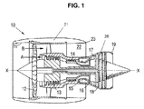
- a ducted fan gas turbine engine is generally indicated at 10 and has a principal and rotational axis X-X.
- the engine comprises, in axial flow series, an air intake 11, a propulsive fan 12, an intermediate pressure compressor 13, a high-pressure compressor 14, combustion equipment 15, a high-pressure turbine 16, an intermediate pressure turbine 17, a low-pressure turbine 18 and a core engine exhaust nozzle 19.
- a nacelle 21 generally surrounds the engine 10 and defines the intake 11, a bypass duct 22 and a bypass exhaust nozzle 23.
- air entering the intake 11 is accelerated by the fan 12 to produce two air flows: a first air flow A into the intermediate pressure compressor 13 and a second air flow B which passes through the bypass duct 22 to provide propulsive thrust.
- the intermediate pressure compressor 13 compresses the air flow A directed into it before delivering that air to the high pressure compressor 14 where further compression takes place.
- the compressed air exhausted from the high-pressure compressor 14 is directed into the combustion equipment 15 where it is mixed with fuel and the mixture combusted.
- the resultant hot combustion products then expand through, and thereby drive the high, intermediate and low-pressure turbines 16, 17, 18 before being exhausted through the nozzle 19 to provide additional propulsive thrust.
- the high, intermediate and low-pressure turbines respectively drive the high and intermediate pressure compressors 14, 13 and the fan 12 by suitable interconnecting shafts.
- the compressors each comprise a number of rotor discs, each carrying a set of rotor blades having an aerofoil configuration.
- the discs are bolted or welded together to form a compressor drum.
- the rotor blades may be affixed to the discs in an axial or a circumferential fixing arrangement. Circumferential fixing is generally used in the rear stages of the compressors as it is simpler and cheaper (albeit less robust) than axial fixing.
- Circumferential fixing involves machining a circumferentially-extending groove around the outer rim of each disc and then slotting the blade roots into the groove.
- the circumferentially-extending groove typically has a symmetrical dove-tailed profile with multiple radii in the bulb of the dovetail to minimise stresses within the groove arising from loads applied by the blades. Minimising stresses within the groove allows a reduction in the amount and therefore weight of disc material surrounding the groove. Reduced weight leads to increased engine efficiency.
- the bridging section provides bracing between circumferential grooves on adjacent rotor discs above the gauge plane of the rotor disc and limits distortion under the blade loads in operation.
- Static vanes can project from an outer casing towards the bridging sections.
- a spacer portion spaces adjacent rotor discs on an opposing side of the rotor disc to the bridging section.
- the present invention provides a rotor disc having an enlarged radially outer rim defining a circumferentially-extending dovetail groove for housing the root portion of a rotor blade, the groove having a groove axis wherein the groove is unsymmetrical about a radially-extending plane through the groove axis.
- a rotor disc e.g. a rotor disc in a compressor drum, has differing stresses and differing structural requirements at opposing axial ends.
- a circumferential groove in a rotor disc having a bridging section on one axial end will be braced on the side proximal the bridging section and will experience higher stresses on the side distal the bridging section.
- Using a circumferential groove that is unsymmetrical about a radially-extending plane through the groove axis allows consideration and accommodation of the differing stresses/structural requirements at opposing axial ends of the rotor disc in order to minimise stresses and thus allow maximum reduction in disc material around the groove.
- a dovetail groove is one that has a restricted radially outer opening extending to an enlarged radially inner bulb profile having two axially opposed curved surfaces.
- the radially inner dovetail bulb profile may have two inclined shoulder surfaces extending from the restricted opening to the respective curved surface.
- the two curved surfaces may be joined by a planar surface forming the base of the groove.
- the curved surfaces may be unsymmetrical about the radially-extending plane through groove axis, for example, one of the curved surfaces may be a multi-radii surface whilst the other has a single radius and/or the radius of one of the curved surfaces may be greater than the radius (radii) of the other curved surface.
- Each curved surface may have a respective radially outer section and radially inner section.
- the radially outer sections and/or the radially inner sections of the curved surface may both/each be unsymmetrical about the radially-extending plane through groove axis.
- the rotor disc further comprises a bridging section for connection (e.g. by welding) to an adjacent rotor disc.
- the bridging section extends axially from the radially outer rim such that its radially outer surface is radially aligned with or radially outwards of the opening of the groove i.e. above the gauge plane of the disc.
- the curved surface proximal to the bridging section has a greater radius of curvature than the curved surface distal the bridging section.
- the curved surface distal the bridging section has a multi-radii profile. This helps reduce stresses in the areas that are not braced by the bridging section.
- the radially inner sections of the curved surfaces each have a respective radius with the radially inner section of the curved surface proximal the bridging section having a greater radius than the curved surface distal the bridging section i.e. the inner sections of the curved surfaces are unsymmetrical about the radially extending plane through the groove axis.
- the radially outer section of the curved surface proximal the bridging section has a single radius and the radially outer section of the curved surface distal the bridging section is a multi-radii surface i.e. the outer sections of the curved surfaces are unsymmetrical about the radially extending plane through the groove axis.
- the enlarged outer rim of the rotor disc has an exterior surface.
- the distance from the groove to the exterior surface of the rim proximal the bridging section is less than the distance from the groove to the exterior surface of the rim distal the bridging section.
- the present invention provides a compressor drum having at least one rotor disc according to the first aspect.
- the compressor drum comprises two rotor discs according to the first aspect with the two rotor disc arranged adjacent one another with the bridging sections joined e.g. by bolting or welding (such as inertia welding).
- the present invention provides a gas turbine engine having a rotor disc according to the first aspect or a compressor drum according to the second aspect.
- Figure 2 shows the radially outer portion of a rotor disc 32 having an enlarged radially outer rim 31 defining a circumferentially-extending dovetail groove 30 for housing the root portion of a rotor blade (not shown).
- the groove has a groove axis and the groove 30 is unsymmetrical about a radially extending plane 35 through the groove axis as discussed below.
- the dovetail groove 30 has a restricted radially outer opening 36 extending to an enlarged radially inner bulb profile 33.
- the radially inner dovetail bulb profile 33 has two inclined shoulder surfaces 37, 37' extending from the restricted opening 36 to a respective curved surface.
- the two curved surfaces are axially opposed (across the axis of the rotor disc) and are joined by a planar surface 39 forming the base of the groove 30 (radially opposite the restricted opening).
- Each curved surface has a respective radially outer section 38A, 38A' and radially inner section 38B, 38B'.
- the rotor disc 32 further comprises a bridging section 34 for connection (e.g. by inertia welding) to an adjacent rotor disc 32'.
- the bridging section 34 extends axially from the radially outer rim 31 such that its radially outer surface 40 is radially aligned with or radially outwards of the opening 36 of the groove 30 i.e. above the gauge plane of the rotor disc.
- the bridging section 34 abuts a bridging section 34' on the adjacent rotor disc 32' and the bridging sections 34, 34' act to provide bracing between the circumferential grooves on adjacent rotor discs 32, 32' above the gauge plane 43 of the rotor disc 32 and to limit distortion under the blade loads in operation.
- a spacer portion 42 is provided between the rotor disc 32 and another rotor disc 32" on the opposing side of the circumferential groove 30 to the bridging section 34.
- the radially outer section 38A' of the curved surface proximal the bridging section 34 has a single radius (R2) whilst the radially outer section 38A of the curved surface distal the bridging section 34 has a multiple radii (R2 and R4) i.e. the outer sections 38A, 38A' of the curved surfaces are unsymmetrical about radially extending plane 35 through the groove axis.
- the radially inner sections 38B, 38B' of the curved surfaces both have a single radius with the radially inner section 38B' of the curved surface proximal the bridging section 34 having a greater radius of curvature (R5.3) than the radius of curvature (R4) of the radially inner section 38B of the curved surface distal the bridging section 34 i.e. the inner sections 38B, 38B' of the curved surfaces are unsymmetrical about the radially extending plane 35 through the groove axis.
- the enlarged outer rim 31 of the rotor disc 32 has an exterior surface 41 distal the bridging portion 34 and an exterior surface 41' proximal the bridging section 34.
- the distance from the groove 30 to the exterior surface 41' of the rim 31 proximal the bridging section 34 is less than the distance from the groove 30 to the exterior surface 41 of the rim 31 distal the bridging section 34.
- the dotted lines in Figure 2 show a radially outer portion of a prior art rotor disc with a symmetrical circumferential groove. It can be seen that the change in shape of the circumferential groove allows material to be removed from the exterior surface 41' which, in turn reduces component weight and stresses at the weld join. The amount of material that can be removed is greater than the amount of material that is added as a result of having a greater radius of curvature in the radially inner section 38B' of the curved surface proximal the bridging section 34 thus resulting in a reduction in component weight.
Landscapes
- Engineering & Computer Science (AREA)
- Mechanical Engineering (AREA)
- General Engineering & Computer Science (AREA)
- Structures Of Non-Positive Displacement Pumps (AREA)
Abstract
Description
- The present invention relates to rotor disc such as a rotor disc for supporting a set of compressor blades in a gas turbine engine.
- With reference to
Figure 1 , a ducted fan gas turbine engine is generally indicated at 10 and has a principal and rotational axis X-X. The engine comprises, in axial flow series, anair intake 11, apropulsive fan 12, anintermediate pressure compressor 13, a high-pressure compressor 14,combustion equipment 15, a high-pressure turbine 16, anintermediate pressure turbine 17, a low-pressure turbine 18 and a coreengine exhaust nozzle 19. Anacelle 21 generally surrounds theengine 10 and defines theintake 11, abypass duct 22 and abypass exhaust nozzle 23. - During operation, air entering the
intake 11 is accelerated by thefan 12 to produce two air flows: a first air flow A into theintermediate pressure compressor 13 and a second air flow B which passes through thebypass duct 22 to provide propulsive thrust. Theintermediate pressure compressor 13 compresses the air flow A directed into it before delivering that air to thehigh pressure compressor 14 where further compression takes place. - The compressed air exhausted from the high-
pressure compressor 14 is directed into thecombustion equipment 15 where it is mixed with fuel and the mixture combusted. The resultant hot combustion products then expand through, and thereby drive the high, intermediate and low-pressure turbines nozzle 19 to provide additional propulsive thrust. The high, intermediate and low-pressure turbines respectively drive the high andintermediate pressure compressors fan 12 by suitable interconnecting shafts. - The compressors each comprise a number of rotor discs, each carrying a set of rotor blades having an aerofoil configuration. The discs are bolted or welded together to form a compressor drum. The rotor blades may be affixed to the discs in an axial or a circumferential fixing arrangement. Circumferential fixing is generally used in the rear stages of the compressors as it is simpler and cheaper (albeit less robust) than axial fixing.
- Circumferential fixing involves machining a circumferentially-extending groove around the outer rim of each disc and then slotting the blade roots into the groove.
- The circumferentially-extending groove typically has a symmetrical dove-tailed profile with multiple radii in the bulb of the dovetail to minimise stresses within the groove arising from loads applied by the blades. Minimising stresses within the groove allows a reduction in the amount and therefore weight of disc material surrounding the groove. Reduced weight leads to increased engine efficiency.
- It is known to provide a bridging section between adjacent rotor discs. The bridging section provides bracing between circumferential grooves on adjacent rotor discs above the gauge plane of the rotor disc and limits distortion under the blade loads in operation. Static vanes can project from an outer casing towards the bridging sections. A spacer portion spaces adjacent rotor discs on an opposing side of the rotor disc to the bridging section.
- Reducing the amount of disc material around the circumferentially-extending groove proximal the bridging section leads to a desirable weight reduction as discussed above and, furthermore, reduces stresses at the weld join between adjacent discs by reducing the thermal gradient between the weld and the rim. However, stresses are increased in the thinned area of the rotor disc.
- It is a preferred aim of the present invention to provide a disc structure that can minimise the weight of the disc whilst maintaining acceptable stresses for the life of the compressor.
- In a first aspect, the present invention provides a rotor disc having an enlarged radially outer rim defining a circumferentially-extending dovetail groove for housing the root portion of a rotor blade, the groove having a groove axis wherein the groove is unsymmetrical about a radially-extending plane through the groove axis.
- A rotor disc e.g. a rotor disc in a compressor drum, has differing stresses and differing structural requirements at opposing axial ends. For example, a circumferential groove in a rotor disc having a bridging section on one axial end, will be braced on the side proximal the bridging section and will experience higher stresses on the side distal the bridging section. Using a circumferential groove that is unsymmetrical about a radially-extending plane through the groove axis allows consideration and accommodation of the differing stresses/structural requirements at opposing axial ends of the rotor disc in order to minimise stresses and thus allow maximum reduction in disc material around the groove.
- Optional features of the invention will now be set out. These are applicable singly or in any combination with any aspect of the invention.
- A dovetail groove is one that has a restricted radially outer opening extending to an enlarged radially inner bulb profile having two axially opposed curved surfaces.
- The radially inner dovetail bulb profile may have two inclined shoulder surfaces extending from the restricted opening to the respective curved surface. The two curved surfaces may be joined by a planar surface forming the base of the groove.
- The curved surfaces may be unsymmetrical about the radially-extending plane through groove axis, for example, one of the curved surfaces may be a multi-radii surface whilst the other has a single radius and/or the radius of one of the curved surfaces may be greater than the radius (radii) of the other curved surface.
- Each curved surface may have a respective radially outer section and radially inner section.
- The radially outer sections and/or the radially inner sections of the curved surface may both/each be unsymmetrical about the radially-extending plane through groove axis.
- In some embodiments, the rotor disc further comprises a bridging section for connection (e.g. by welding) to an adjacent rotor disc. In some embodiments, the bridging section extends axially from the radially outer rim such that its radially outer surface is radially aligned with or radially outwards of the opening of the groove i.e. above the gauge plane of the disc.
- In some embodiments, the curved surface proximal to the bridging section has a greater radius of curvature than the curved surface distal the bridging section.
- In some embodiments, the curved surface distal the bridging section has a multi-radii profile. This helps reduce stresses in the areas that are not braced by the bridging section.
- In some embodiments, the radially inner sections of the curved surfaces each have a respective radius with the radially inner section of the curved surface proximal the bridging section having a greater radius than the curved surface distal the bridging section i.e. the inner sections of the curved surfaces are unsymmetrical about the radially extending plane through the groove axis.
- In some embodiments, the radially outer section of the curved surface proximal the bridging section has a single radius and the radially outer section of the curved surface distal the bridging section is a multi-radii surface i.e. the outer sections of the curved surfaces are unsymmetrical about the radially extending plane through the groove axis.
- The enlarged outer rim of the rotor disc has an exterior surface.
- In some embodiments, the distance from the groove to the exterior surface of the rim proximal the bridging section is less than the distance from the groove to the exterior surface of the rim distal the bridging section.
- In a second aspect, the present invention provides a compressor drum having at least one rotor disc according to the first aspect.
- In some embodiments, the compressor drum comprises two rotor discs according to the first aspect with the two rotor disc arranged adjacent one another with the bridging sections joined e.g. by bolting or welding (such as inertia welding).
- In a third aspect, the present invention provides a gas turbine engine having a rotor disc according to the first aspect or a compressor drum according to the second aspect.
- Embodiments of the invention will now be described by way of example with reference to the accompanying drawings in which:
-
Figure 1 shows a ducted fan gas turbine engine; -
Figure 2 shows a radially outer portion of a rotor disc according to a first embodiment of the present invention with dotted lines showing a radially outer portion of a prior art rotor disc; and -
Figure 3 shows three adjacent rotor discs with two of the rotor discs being according to the first embodiment of the present invention. -
Figure 2 shows the radially outer portion of arotor disc 32 having an enlarged radiallyouter rim 31 defining a circumferentially-extendingdovetail groove 30 for housing the root portion of a rotor blade (not shown). The groove has a groove axis and thegroove 30 is unsymmetrical about a radially extendingplane 35 through the groove axis as discussed below. - The
dovetail groove 30 has a restricted radiallyouter opening 36 extending to an enlarged radiallyinner bulb profile 33. - The radially inner
dovetail bulb profile 33 has twoinclined shoulder surfaces 37, 37' extending from the restrictedopening 36 to a respective curved surface. The two curved surfaces are axially opposed (across the axis of the rotor disc) and are joined by aplanar surface 39 forming the base of the groove 30 (radially opposite the restricted opening). - Each curved surface has a respective radially
outer section inner section - As shown in
Figures 2 and3 , therotor disc 32 further comprises abridging section 34 for connection (e.g. by inertia welding) to an adjacent rotor disc 32'. Thebridging section 34 extends axially from the radiallyouter rim 31 such that its radiallyouter surface 40 is radially aligned with or radially outwards of theopening 36 of thegroove 30 i.e. above the gauge plane of the rotor disc. Thebridging section 34 abuts a bridging section 34' on the adjacent rotor disc 32' and the bridgingsections 34, 34' act to provide bracing between the circumferential grooves onadjacent rotor discs 32, 32' above thegauge plane 43 of therotor disc 32 and to limit distortion under the blade loads in operation. Aspacer portion 42 is provided between therotor disc 32 and anotherrotor disc 32" on the opposing side of thecircumferential groove 30 to thebridging section 34. - The radially
outer section 38A' of the curved surface proximal thebridging section 34 has a single radius (R2) whilst the radiallyouter section 38A of the curved surface distal thebridging section 34 has a multiple radii (R2 and R4) i.e. theouter sections plane 35 through the groove axis. - The radially
inner sections inner section 38B' of the curved surface proximal thebridging section 34 having a greater radius of curvature (R5.3) than the radius of curvature (R4) of the radiallyinner section 38B of the curved surface distal thebridging section 34 i.e. theinner sections radially extending plane 35 through the groove axis. - The enlarged
outer rim 31 of therotor disc 32 has anexterior surface 41 distal the bridgingportion 34 and an exterior surface 41' proximal thebridging section 34. The distance from thegroove 30 to the exterior surface 41' of therim 31 proximal thebridging section 34 is less than the distance from thegroove 30 to theexterior surface 41 of therim 31 distal thebridging section 34. - The dotted lines in
Figure 2 show a radially outer portion of a prior art rotor disc with a symmetrical circumferential groove. It can be seen that the change in shape of the circumferential groove allows material to be removed from the exterior surface 41' which, in turn reduces component weight and stresses at the weld join. The amount of material that can be removed is greater than the amount of material that is added as a result of having a greater radius of curvature in the radiallyinner section 38B' of the curved surface proximal thebridging section 34 thus resulting in a reduction in component weight. - While the invention has been described in conjunction with the exemplary embodiments described above, many equivalent modifications and variations will be apparent to those skilled in the art when given this disclosure. Accordingly, the exemplary embodiments of the invention set forth above are considered to be illustrative and not limiting. Various changes to the described embodiments may be made without departing from the scope of the invention.
Claims (15)
- A rotor disc (32) having an enlarged radially outer rim (31) defining a circumferentially-extending dovetail groove (30) for housing the root portion of a rotor blade, the groove having a groove axis wherein the groove is unsymmetrical about a radially-extending plane (35) through the groove axis.
- A rotor disc according to claim 1 wherein the dovetail groove has a restricted radially outer opening (36) extending to an enlarged radially inner bulb profile (33) having a pair of axially opposed curved surfaces (38A, B; 38A', B').
- A rotor disc according to claim 1 or 2 wherein the opposing curved surfaces are unsymmetrical about the radially-extending plane through the groove axis.
- A rotor disc according to claim 2 or 3 wherein one of the opposing curved surfaces (38A) is a multi-radii surface whilst the other (38A') has a single radius and/or the radius of one of the opposing curved surfaces is greater than the radius (radii) of the other curved surface.
- A rotor disc according to any one of claims 2 to 4 wherein each curved surface has a respective radially outer section (38A, A') and radially inner section (38B, B').
- A rotor disc according to claim 5 wherein the radially outer sections and the radially inner sections of the curved surface are each unsymmetrical about the radially-extending plane through the groove axis.
- A rotor disc according to any one of the preceding claims further comprising a bridging section (34) for connection to an adjacent rotor disc (32').
- A rotor disc according to claim 7 wherein the bridging section extends from the radially outer rim such that its radially outer surface (40) is radially outwards of the opening of the groove.
- A rotor disc according to claim 7 or 8 wherein the dovetail groove has a restricted radially outer opening extending to an enlarged radially inner bulb profile having a pair of axially opposed curved surfaces (38B, B') and wherein the curved surface proximal the bridging section (38B') has a greater radius of curvature (R5.3) than the curved surface distal the bridging section (38B).
- A rotor disc according to any one of claims 7 to 9 wherein the dovetail groove has a restricted radially outer opening extending to an enlarged radially inner bulb profile having a pair of axially opposed curved surfaces (38A, A') and wherein the curved surface distal the bridging section (38A) has a multi-radii (R2, R4) profile.
- A rotor disc according to any one of claims 7 to 10 wherein:the dovetail groove has a restricted radially outer opening extending to an enlarged radially inner bulb profile having a pair of axially opposed curved surfaces;each curved surface has a respective radially outer section (38A, A') and radially inner section (38B, B'); andthe radially inner sections of the curved surfaces each have a respective radius with the radially inner section of the curved surface proximal the bridging section (38B') having a greater radius (R5.3) than the curved surface distal the bridging section (38B).
- A rotor disc according to any one of claims 7 to 11 wherein:the dovetail groove has a restricted radially outer opening extending to an enlarged radially inner bulb profile having a pair of axially opposed curved surfaces;each curved surface has a respective radially outer section (38A, A') and radially inner section (38B, B'); andthe radially outer section of the curved surface distal the bridging section (38A) has a multi-radii (R2, R4) surface.
- A rotor disc according to any one of claims 7 to 12 wherein a distance from the groove to an exterior surface of the rim proximal the bridging section is less than the distance from the groove to an exterior surface of the rim distal the bridging section.
- A compressor drum comprising at least one rotor disc according to any one of the preceding claims.
- A compressor drum comprising two rotor discs according to any one of claims 7 to 13 the two rotor discs arranged adjacent one another with the bridging sections joined.
Applications Claiming Priority (1)
| Application Number | Priority Date | Filing Date | Title |
|---|---|---|---|
| GB201502612A GB201502612D0 (en) | 2015-02-17 | 2015-02-17 | Rotor disc |
Publications (1)
| Publication Number | Publication Date |
|---|---|
| EP3059389A1 true EP3059389A1 (en) | 2016-08-24 |
Family
ID=52781713
Family Applications (1)
| Application Number | Title | Priority Date | Filing Date |
|---|---|---|---|
| EP16152912.8A Withdrawn EP3059389A1 (en) | 2015-02-17 | 2016-01-27 | Gas turbine rotor disc with assymetric circumferential slot |
Country Status (3)
| Country | Link |
|---|---|
| US (1) | US10001134B2 (en) |
| EP (1) | EP3059389A1 (en) |
| GB (1) | GB201502612D0 (en) |
Citations (6)
| Publication number | Priority date | Publication date | Assignee | Title |
|---|---|---|---|---|
| GB2100809A (en) * | 1981-06-29 | 1983-01-06 | Gen Electric | Root formation for rotor blade |
| US5584658A (en) * | 1994-08-03 | 1996-12-17 | Societe Nationale D'etude Et De Construction De Moteurs D'aviation "Snecma" | Turbocompressor disk provided with an asymmetrical circular groove |
| DE102010001329A1 (en) * | 2010-01-28 | 2011-08-18 | Rolls-Royce Deutschland Ltd & Co KG, 15827 | Method for welding rotor disc of axial fluid flow machine e.g. gas turbine, involves checking quality of friction weld between intermediate elements, and welding intermediate elements with respective rotor discs |
| EP2615251A1 (en) * | 2012-01-13 | 2013-07-17 | General Electric Company | Rotor for a turbomachine |
| CN103850715A (en) * | 2012-11-30 | 2014-06-11 | 西门子公司 | Rotor wheel disc |
| US20140377070A1 (en) * | 2013-06-25 | 2014-12-25 | Techspace Aero S.A. | Axial Turbomachine Compressor Drum with Dual Means of Blade Fixing |
Family Cites Families (7)
| Publication number | Priority date | Publication date | Assignee | Title |
|---|---|---|---|---|
| US2295012A (en) * | 1941-03-08 | 1942-09-08 | Westinghouse Electric & Mfg Co | Turbine blading |
| US5160242A (en) * | 1991-05-31 | 1992-11-03 | Westinghouse Electric Corp. | Freestanding mixed tuned steam turbine blade |
| US5310318A (en) * | 1993-07-21 | 1994-05-10 | General Electric Company | Asymmetric axial dovetail and rotor disk |
| DE4324960A1 (en) * | 1993-07-24 | 1995-01-26 | Mtu Muenchen Gmbh | Impeller of a turbomachine, in particular a turbine of a gas turbine engine |
| FR2857405B1 (en) * | 2003-07-07 | 2005-09-30 | Snecma Moteurs | IMPROVING THE RETENTION CAPACITY OF A DISSYMMETRIC HAMMER BLADE |
| DE102004051116A1 (en) * | 2004-10-20 | 2006-04-27 | Mtu Aero Engines Gmbh | Rotor of a turbomachine, in particular gas turbine rotor |
| US9068465B2 (en) * | 2012-04-30 | 2015-06-30 | General Electric Company | Turbine assembly |
-
2015
- 2015-02-17 GB GB201502612A patent/GB201502612D0/en not_active Ceased
-
2016
- 2016-01-27 EP EP16152912.8A patent/EP3059389A1/en not_active Withdrawn
- 2016-01-29 US US15/009,934 patent/US10001134B2/en not_active Expired - Fee Related
Patent Citations (6)
| Publication number | Priority date | Publication date | Assignee | Title |
|---|---|---|---|---|
| GB2100809A (en) * | 1981-06-29 | 1983-01-06 | Gen Electric | Root formation for rotor blade |
| US5584658A (en) * | 1994-08-03 | 1996-12-17 | Societe Nationale D'etude Et De Construction De Moteurs D'aviation "Snecma" | Turbocompressor disk provided with an asymmetrical circular groove |
| DE102010001329A1 (en) * | 2010-01-28 | 2011-08-18 | Rolls-Royce Deutschland Ltd & Co KG, 15827 | Method for welding rotor disc of axial fluid flow machine e.g. gas turbine, involves checking quality of friction weld between intermediate elements, and welding intermediate elements with respective rotor discs |
| EP2615251A1 (en) * | 2012-01-13 | 2013-07-17 | General Electric Company | Rotor for a turbomachine |
| CN103850715A (en) * | 2012-11-30 | 2014-06-11 | 西门子公司 | Rotor wheel disc |
| US20140377070A1 (en) * | 2013-06-25 | 2014-12-25 | Techspace Aero S.A. | Axial Turbomachine Compressor Drum with Dual Means of Blade Fixing |
Also Published As
| Publication number | Publication date |
|---|---|
| US20160238020A1 (en) | 2016-08-18 |
| GB201502612D0 (en) | 2015-04-01 |
| US10001134B2 (en) | 2018-06-19 |
Similar Documents
| Publication | Publication Date | Title |
|---|---|---|
| US11073021B2 (en) | Mistuned airfoil assemblies | |
| US9828858B2 (en) | Turbine blade airfoil and tip shroud | |
| US9822647B2 (en) | High chord bucket with dual part span shrouds and curved dovetail | |
| US20080304972A1 (en) | Rotary body for turbo machinery with mistuned blades | |
| US9556741B2 (en) | Shrouded blade for a gas turbine engine | |
| US9464530B2 (en) | Turbine bucket and method for balancing a tip shroud of a turbine bucket | |
| US20170306768A1 (en) | Turbine engine shroud assembly | |
| US11927108B2 (en) | Integrated bladed rotor | |
| US20170356298A1 (en) | Stator vane | |
| US11073031B2 (en) | Blade for a gas turbine engine | |
| US20150098832A1 (en) | Method and system for relieving turbine rotor blade dovetail stress | |
| EP3693541B1 (en) | Gas turbine rotor disk having scallop shield feature | |
| US20180128118A1 (en) | Turbine airfoil attachment with multi-radial serration profile | |
| US9470098B2 (en) | Axial compressor and method for controlling stage-to-stage leakage therein | |
| EP3372786B1 (en) | High-pressure compressor rotor blade with leading edge having indent segment | |
| EP3091189A1 (en) | Airfoil assembly for a stator of a gas turbine engine compressor | |
| US9422819B2 (en) | Rotor blade root spacer for arranging between a rotor disk and a root of a rotor blade | |
| US10577961B2 (en) | Turbine disk with blade supported platforms | |
| US9359906B2 (en) | Rotor blade root spacer with a fracture feature | |
| US10001134B2 (en) | Rotor disc | |
| US20200011188A1 (en) | Blade for a gas turbine engine | |
| US10641108B2 (en) | Turbine blade shroud for gas turbine engine with power turbine and method of manufacturing same | |
| US20180172027A1 (en) | Gas turbine engine |
Legal Events
| Date | Code | Title | Description |
|---|---|---|---|
| PUAI | Public reference made under article 153(3) epc to a published international application that has entered the european phase |
Free format text: ORIGINAL CODE: 0009012 |
|
| AK | Designated contracting states |
Kind code of ref document: A1 Designated state(s): AL AT BE BG CH CY CZ DE DK EE ES FI FR GB GR HR HU IE IS IT LI LT LU LV MC MK MT NL NO PL PT RO RS SE SI SK SM TR |
|
| AX | Request for extension of the european patent |
Extension state: BA ME |
|
| STAA | Information on the status of an ep patent application or granted ep patent |
Free format text: STATUS: REQUEST FOR EXAMINATION WAS MADE |
|
| 17P | Request for examination filed |
Effective date: 20170214 |
|
| RBV | Designated contracting states (corrected) |
Designated state(s): AL AT BE BG CH CY CZ DE DK EE ES FI FR GB GR HR HU IE IS IT LI LT LU LV MC MK MT NL NO PL PT RO RS SE SI SK SM TR |
|
| STAA | Information on the status of an ep patent application or granted ep patent |
Free format text: STATUS: EXAMINATION IS IN PROGRESS |
|
| 17Q | First examination report despatched |
Effective date: 20181102 |
|
| RAP1 | Party data changed (applicant data changed or rights of an application transferred) |
Owner name: ROLLS-ROYCE PLC |
|
| GRAP | Despatch of communication of intention to grant a patent |
Free format text: ORIGINAL CODE: EPIDOSNIGR1 |
|
| STAA | Information on the status of an ep patent application or granted ep patent |
Free format text: STATUS: GRANT OF PATENT IS INTENDED |
|
| INTG | Intention to grant announced |
Effective date: 20200514 |
|
| STAA | Information on the status of an ep patent application or granted ep patent |
Free format text: STATUS: THE APPLICATION IS DEEMED TO BE WITHDRAWN |
|
| 18D | Application deemed to be withdrawn |
Effective date: 20200925 |