EP3058549B1 - Converting an image from a dual-band sensor to a visible color image - Google Patents
Converting an image from a dual-band sensor to a visible color image Download PDFInfo
- Publication number
- EP3058549B1 EP3058549B1 EP14787350.9A EP14787350A EP3058549B1 EP 3058549 B1 EP3058549 B1 EP 3058549B1 EP 14787350 A EP14787350 A EP 14787350A EP 3058549 B1 EP3058549 B1 EP 3058549B1
- Authority
- EP
- European Patent Office
- Prior art keywords
- image
- band
- dual
- component
- sensor
- Prior art date
- Legal status (The legal status is an assumption and is not a legal conclusion. Google has not performed a legal analysis and makes no representation as to the accuracy of the status listed.)
- Active
Links
Images




Classifications
-
- H—ELECTRICITY
- H04—ELECTRIC COMMUNICATION TECHNIQUE
- H04N—PICTORIAL COMMUNICATION, e.g. TELEVISION
- H04N9/00—Details of colour television systems
- H04N9/77—Circuits for processing the brightness signal and the chrominance signal relative to each other, e.g. adjusting the phase of the brightness signal relative to the colour signal, correcting differential gain or differential phase
-
- G—PHYSICS
- G06—COMPUTING OR CALCULATING; COUNTING
- G06T—IMAGE DATA PROCESSING OR GENERATION, IN GENERAL
- G06T5/00—Image enhancement or restoration
- G06T5/50—Image enhancement or restoration using two or more images, e.g. averaging or subtraction
-
- H—ELECTRICITY
- H04—ELECTRIC COMMUNICATION TECHNIQUE
- H04N—PICTORIAL COMMUNICATION, e.g. TELEVISION
- H04N23/00—Cameras or camera modules comprising electronic image sensors; Control thereof
- H04N23/20—Cameras or camera modules comprising electronic image sensors; Control thereof for generating image signals from infrared radiation only
-
- G—PHYSICS
- G06—COMPUTING OR CALCULATING; COUNTING
- G06T—IMAGE DATA PROCESSING OR GENERATION, IN GENERAL
- G06T2207/00—Indexing scheme for image analysis or image enhancement
- G06T2207/10—Image acquisition modality
- G06T2207/10024—Color image
-
- G—PHYSICS
- G06—COMPUTING OR CALCULATING; COUNTING
- G06T—IMAGE DATA PROCESSING OR GENERATION, IN GENERAL
- G06T2207/00—Indexing scheme for image analysis or image enhancement
- G06T2207/10—Image acquisition modality
- G06T2207/10048—Infrared image
-
- G—PHYSICS
- G06—COMPUTING OR CALCULATING; COUNTING
- G06T—IMAGE DATA PROCESSING OR GENERATION, IN GENERAL
- G06T2207/00—Indexing scheme for image analysis or image enhancement
- G06T2207/20—Special algorithmic details
- G06T2207/20212—Image combination
- G06T2207/20221—Image fusion; Image merging
Definitions
- the present invention relates generally to converting an image from a dual-band sensor to a visible color image based on wavelet-based image fusion and a characteristic of the human visual system.
- a dual-band Forward Looking Infrared (FLIR) camera employs two different sets of sensing elements to detect infrared radiation.
- the two types of sensors include a long-wave infrared (LW or LWIR, wavelength 8-12 ⁇ m) sensor and a mid-wave infrared (MW or MWIR, wavelength 3-5 ⁇ m) sensor.
- LW images from data generated by the LW sensor are based on emitted energy
- the MW images from data generated by the MW sensor are based on emitted energy plus reflected energy, where reflected energy is prevalent in the daytime.
- Similar but slightly different monochrome images can be constructed from data generated by each of the sensors.
- human viewers may have difficulty combining the two images in their minds to create a combined representation of the two monochrome images that accounts for different phenomenological features that may be embedded within the two bands.
- the LW image and the MW image can be combined into a single image with each pixel having a vector of size two (represented as ⁇ LW, MW ⁇ ).
- a human can perceive phenomenological features in the combined image mapped to two channels of a color display better than in two separate grayscale images. Even more of the phenomenology is perceivable when features of the combined image are displayed in full visual color, using all three channels (e.g., red channel, green channel, and blue channel) of a color display.
- the human visual system can directly perceive images within the visible spectrum, which includes three partially overlapping bands: the red band (R), the green band (G) and the blue band (B), such that each pixel of a visible image is a vector of length three ⁇ R, G, B ⁇ .
- Kin-Wen Tian "Novel method on dual-band infrared image fusion for dim small target detection", Optical Engineering, vol. 46, no. 11, November 2007 describes a fractal dimension algorithm that fuses mid-wave and long-wave infrared images and detects targets. Usually, the targets in infrared images are man-made, and their fractal dimensions are different from that of their natural background.
- the source images are first decomposed by wavelet transformation. Then in the wavelet transformation domain, fractal dimensions are calculated and fusion rules that merge corresponding sub images of two matching source images are set up, and new sub images are created. Finally, the image is reconstructed by inverse wavelet transformation and a fused image is obtained.
- US2006/006331 discloses a method for representing the front field of vision from a motor vehicle on a display panel of a display includes sensing, by an infrared camera system, the field of vision and feeding corresponding infrared data to a data processing unit.
- One embodiment includes an apparatus associated with a processor that facilitates the execution of machine readable instructions to convert an image from a dual-band sensor to a visible color image.
- the machine readable instructions can facilitate conversion of the image from the dual-band image sensor to a placeholder image in a placeholder color space.
- the placeholder color space is established based on wavelet-based image fusion and an oppositional color processing technique used by the human visual system.
- the machine readable instructions can also facilitate mapping the placeholder image to a visible color space to create the visible color image.
- Another embodiment includes a non-transitory computer-readable storage medium storing instructions executable by an associated processor to perform a method for converting an image from a dual-band sensor to a visible color image.
- the method includes converting the image from the dual-band sensor to a placeholder image in a placeholder color space.
- the placeholder color space is established based on wavelet-based image fusion and an oppositional color processing technique used by the human visual system to perceive colors.
- An aspect of the converting includes reducing redundancy between a first component of the image from the dual-band sensor from a first channel and a second component of the image from the dual-band sensor from a second channel.
- the method also includes mapping the placeholder image into a visible color space to create the visible color image.
- a further embodiment includes a non-transitory computer-readable device storing executable instructions executable by an associated processor to perform operations that convert a dual-band image to a visible color image.
- the operations include reducing noise in the dual-band image and standardizing a dynamic range between a first component of the image from the dual-band sensor from a first channel and a dynamic range of a second component of the image from the dual-band sensor from a second channel.
- the operations also include converting the dual-band image with reduced noise and standardized dynamic range to a placeholder image within a placeholder color space that is established based on wavelet-based image fusion and an oppositional color processing technique used by the human visual system.
- the operations further include transforming the placeholder to a visible color space to create the visible color image.
- the present invention relates generally to converting a dual-band image from a dual-band sensor to a three-band visible color image.
- image generally refers to image data that can be displayed by a display device.
- visible color image refers to an image with a red value, a green value and a blue value at each pixel, where each value is within the dynamic range of a standard display (e.g., 8-bits/pixel per color).
- the conversion of the dual-band image to the visible color image can be accomplished via a process that tightly merges wavelet-based image fusion with strategies inspired by the operation of the human visual system.
- the dual-band image is first converted to a placeholder image in a simplified placeholder ⁇ L*, a*, b* ⁇ color space.
- placeholder generally refers to an intermediate product and is a synonym for intermediate, temporary, notational, preliminary, and other similar terms.
- the placeholder ⁇ L*, a*, b* ⁇ color space, as well at the corresponding placeholder ⁇ L*, a*, b* ⁇ image, is generally formed at least in part via floating point arithmetic.
- the L* component of the placeholder ⁇ L*, a*, b* ⁇ color space is generated by fusing images from the bands of the dual-band image using a wavelet-based approach.
- the a* component of the placeholder ⁇ L*, a*, b* ⁇ color space and the b* component of the placeholder ⁇ L*, a*, b* ⁇ color space are generated according to strategies inspired by the human visual system.
- the placeholder image is mapped to visible ⁇ R, G, B ⁇ color space to create the visible color image.
- the visible color image can be displayed by a display device for visual analysis by a human or the data can be exploited by an automated process that uses artificial intelligence.
- System 1 includes at least a sensor 12 (sensor 12 is also referred to herein as “the dual-band sensor 12" or “the dual-band camera 12;” the terms “sensor” and “camera” are used interchangeably herein) and a processor 10.
- the processor 10 receives a dual-band image from dual-band sensor 12 and converts the dual-band image to a placeholder image in a placeholder ⁇ L*, a*, b* ⁇ color space with an L* component, an a* component and a b* component.
- the processor 10 forms the L* component by fusing images in the two bands of the dual-band image using a wavelet-based approach.
- the processor 10 employs strategies inspired by the human visual system to form the a* component and the b* component.
- the processor 10 maps the placeholder image in the placeholder ⁇ L*, a*, b* ⁇ color space to visible ⁇ R, G, B ⁇ color space to generate the visible color image.
- the dual-band sensor can refer to a sensor that can collect data in at least two bands of the electromagnetic spectrum to form a dual-band image and/or two separate sensors that each produces a different band of the image.
- sensors that can be used to generate one or both bands of the dual-band sensor 12 include a long-wave forward-looking infrared (FLIR) sensor, a mid-wave FLIR sensor, fully integrated dual-band long-wave/mid-wave FLIR sensor, a short wave infrared sensor, a monochrome visible sensor, a near infrared sensor, an image intensified image sensor, or any other type of dual-band sensor or combination of two sensors imaging in different bands.
- FLIR long-wave forward-looking infrared
- mid-wave FLIR sensor fully integrated dual-band long-wave/mid-wave FLIR sensor
- a short wave infrared sensor a monochrome visible sensor
- a near infrared sensor an image intensified image sensor
- Post-processing stage(s) of the dual-band image that can facilitate conversion to the visible color image can be performed by a processor within the sensor 12 and/or within a processor 10 that is external to the sensor 12.
- Example post-processing stages include non-uniformity correction, bad pixel correction, and the like.
- the processor 10 is communicatively coupled to the sensor 12 according to a means of communication that enables transfer of image data.
- the processor 10 can be located in a position that facilitates communication with the sensor 12.
- the processor 10 can be housed within the same assembly as the sensor 12, housed within a processor box adjacent to the sensor 12, housed within a processor box separate from the sensor 12, or associated with a display controller, graphical user interface, or the like.
- the processor 10 can include, for example, a real-time processor, a signal processor, a single-board computer, or any other type of processor that can facilitate execution of instructions for converting the dual-band image represented by the data to the visible color image.
- the processor 10 can utilize different types of hardware and/or software filters throughout the conversion (e.g., applied to one or more of the dual-band image, the placeholder image, or the visible color image) to control the sharpness and/or the noise characteristics of the visible color image.
- filters include a mean filter, a median filter, a low-pass filter, a high-pass filter, an unsharp mask filter, and the like.
- the processor 10 can further map the visible color image to a different color space (e.g., to emphasize a feature of the visible color image).
- System 1 optionally can include a memory 16 and/or a display 14.
- the memory 16 can be communicatively coupled to the processor 10 and can store executable instructions that can facilitate the conversion of the dual-band image from the sensor 12 to the visible color image 12 by processor 10.
- the display 14 can be communicatively coupled to the processor 10 to display the visible color image (e.g., to a human user).
- the data that is generated for display 14 can also be further processed according to an artificial intelligence routine.
- the display 14 can include a computer monitor, a video display, or any other type of monitor that can display a visible color image or a motion picture of the visible color image.
- the visible color image can be a still image, a motion picture, or any combination of a still image and a motion picture.
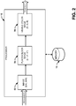
- Processor 10 receives a dual-band image 52 from the FLIR sensor 12.
- the dual-band image 52 includes pixels that are two-dimensional vectors of long-wave data (LW) and mid-wave data (MW), represented as ⁇ LW, MW ⁇ , where LW and MW are assumed to each contain one integer value per pixel.
- LW long-wave data
- MW mid-wave data
- the FLIR sensor 12 captures image data within the LW band and the MW band, virtually simultaneously. It is assumed that the dual-band image 12 has been spatially registered (e.g., by sensor design, processing, etc.) on a pixel-by-pixel basis prior to processing by the processor 10.
- the processor 10 converts the dual-band ⁇ LW, MW ⁇ image to a placeholder image 54.
- the placeholder image can be represented as a vector of size three, ⁇ L*, a*, b* ⁇ .
- the conversion of the dual-band image 52 to the placeholder image 54 can be accomplished via floating point arithmetic employing a technique that merges wavelet-based image fusion with oppositional color processing techniques used by the human visual system.
- the placeholder image 54 is within a placeholder ⁇ L*, a*, b* ⁇ color space that includes an L* component, an a* component and a b* component.
- the processor 10 generates the L* component according to a wavelet-based image fusion approach that fuses the LW component of the dual-band image and the MW component of the dual-band image.
- the processor 10 generates the a* component and the b* component according to oppositional color processing strategies inspired by the human visual system according to the LW component of the dual-band image, the MW component of the dual-band image, and a function of the LW component of the dual-band image and the MW component of the dual-band image.
- the processor 10 generates the visible color image 56 from the placeholder image 54.
- the processor 10 can map the placeholder image 54 in the placeholder ⁇ L*, a*, b* ⁇ space to the visible color image 56 within the red band, the green band and the blue band, which is denoted as a vector of size three, ⁇ R, G, B ⁇ .
- the visible color image 56 can be displayed by a display device (e.g., the display device 14, such as a computer monitor) so that features can be detected by human perception.
- the data related to the visible color image 56 (e.g., in floating point or fixed point form) can be further processed according to an artificial intelligence routine.
- the visible color image 56 can be provided in integer format, one integer per color component per pixel.
- the input (e.g., dual-band image 52) and output (e.g., visible color image 56) images can contain the same number of pixels in the same height to width ratio.
- the output (e.g., visible color image 56) can also be reformatted to meet the requirements of a particular display.
- FIG. 3 An example of the conversion of an LW image 102 and an MW image 104 from a dual-band FLIR sensor to a visible color image 106 is shown in FIG. 3 .
- the processor converts the LW image 102 and the MW image 104 to the placeholder image in the placeholder ⁇ L*, a*, b* ⁇ color space based on wavelet-based image fusion and an oppositional color processing technique used by the human visual system.
- the processor 10 maps the placeholder image to visible ⁇ R, G, B ⁇ color space to generate the visible color image 106.
- the visible color image 106 contains more depth and contrast than either the LW image 102 or the MW image 104.
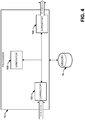
- FIG. 4 illustrated is a system that can be executed by the processor 10 to facilitate the conversion of a dual-band image recorded by a dual-band sensor 12 to a visible color image that can be displayed by a display device 14. Instructions that facilitate the operation of the system can be stored in the memory 16 that is coupled to the processor. As shown in FIG. 4 , the system includes at least a corrector 152, a generator 154, and a converter 156.
- the corrector 152 receives image data representing the dual-band image from the sensor 12.
- the image data includes data captured in the first band and data captured in the second band of the dual-band sensor 12.
- the data captured in the first band and/or data captured in the second band of the dual-band sensor 12 can include anomalies, e.g., abnormally bright pixels or abnormally dark pixels.
- the corrector 152 can eliminate these anomalies via standardization of the dynamic range of the data captured in the first band and/or the data captured in the second band of the dual-band sensor 12. To eliminate the anomalies, the corrector 152 can standardize the dynamic range of data captured in the first band and data captured in the second band of the dual-band sensor 12.
- the corrector 152 checks the data captured in the first band and/or the data captured in the second band of the dual-band sensor 12 for anomalies. For example, the corrector 152 can check the data by examining the histograms of brightness levels related to the data. Assuming that higher gray levels correspond to hotter areas in the scene, certain anomalies often have a much higher gray level than the rest of the data within the band, which is represented as a gap in the right tail of the histogram. These types of anomalies correspond to either the highly non-Gaussian nature of some infrared images or occasionally to uncorrected image errors. The corrector 152 detects the gap and/or the anomalies in the right tail of the histogram and flags the data as an anomaly for standardization.
- Y X , if X ⁇ X 0 X + log X ⁇ X o , if X > X 0
- X is the input gray level
- X 0 is X-value of a point chosen to prevent a large portion of the dynamic range of the image from being used for just a small portion of the image
- Y is the output gray level.
- FIG. 5 An example of a plot that can be used for selection of the X 0 value in the Lin/Log transform is shown in FIG. 5 , where X is the input gray level and Y is the output gray level.
- the inflection point 208 can be chosen to prevent a large portion of the dynamic range of an image from being used for just a small section of the image.
- the X-value of the inflection point 208 can be used as the X 0 value.
- the inflection point 208 can be chosen based on factors including, but not limited to: a number of standard deviations above the image mean, a limitation of the number of pixels subject to the transform, a start of a gap at the right tail of a histogram of grayscale values, or another feature that indicates an anomaly.
- the corrector 152 can reduce noise or non-uniformity within the dual-band image.
- the system can operate without the corrector 152 reducing the noise in the dual-band image, but the system can produce a better visible color image when the dual-band image exhibits low noise.
- the noise that can be reduced in the dual-band image by corrector 152 can include: random spatial-temporal noise, temporal row noise, temporal column noise, random spatial noise, fixed row noise, fixed column noise, frame-to-frame noise, image brightness flicker, thermal vignetting, periodic noise within an image, and the like.
- Corrector 152 can employ standard statistical signal processing or image processing techniques to reduce the different types of noise and/or non-uniformity. Some of the noise types can also be corrected within the dual-band sensor 12.
- the dual-band sensor 12 can employ a thermal reference correction or a scene-based non-uniformity correction to correct for at least a portion of the noise within the dual-band image.
- the generator 154 can generate the placeholder image within the placeholder ⁇ L*, a*, b* ⁇ three-dimensional color space.
- the generator 154 can generate the L* component of the placeholder image by fusing each dimension of the dual-band image according to a wavelet-based approach.
- the generator 154 can generate the a* component and the b* component according to strategies inspired by the human visual system.
- the generator 154 can further expand the dynamic range of the a* component and/or the b* component to reduce the redundancy between the images corresponding to each of the two bands of the dual-band image.
- the generator 154 can generate the a* component and the b* component according to strategies inspired by the human visual system.
- the retina of the human visual system includes rods, which generally perceive a grayscale image, and cones, which generally perceive a color image.
- the cones can perceive the red band, the green band, and the blue band of the visible portion of the electromagnetic spectrum.
- the response of the cones to the red band and the green band is highly overlapping, yet humans perceive red and green as distinct colors due to conversion of the incoming image into an opponency space (referred to as oppositional color processing).
- the placeholder ⁇ L*, a*, b* ⁇ space used in the conversion of a dual-band image to a visible color image mimics the oppositional color processing of the human visual system.
- L*, a* and b* are the orthogonal axes of a three-dimensional coordinate system, where L* represents the luminance or brightness axis, a* represents the Red/Green axis, and b* represents the Blue/Yellow axis.
- the generator 154 can convert the dual-band image recorded by the dual-band sensor 12 into the three visible color channels (Red, Green, Blue) and then convert the RGB image into the placeholder ⁇ L*, a*, b* ⁇ space.
- the blue channel exhibits a strong response for areas that are simultaneously bright (or at least of a high gray scale value) in both the LW and MW thermal imagery.
- the blue channel can be the ratio of the LW and MW pixel values at each pixel location rather than the product of the LW and MW images.
- the blue channel is a chosen function of the LW and MW images. The conversion can be done similarly for other types of dual-band images recorded by other types of dual-band sensors.
- the generator 154 then converts the temporary ⁇ R, G, B ⁇ visible color space to the a* and b* components of the placeholder ⁇ L*, a*, b* ⁇ space. It will be understood by a person having ordinary skill in the art that there are alternative formulations of placeholder color spaces that can be utilized as the placeholder ⁇ L*, a*, b* ⁇ color space by the generator 154. The formulation of the placeholder ⁇ L*, a*, b* ⁇ color space as described herein is but one of many possible examples.
- the a* component is a function of R and G.
- the b* component is a function of B, R and G.
- the generator 154 can expand the dynamic ranges of the a* and b* channels to reduce redundancy between the LW and MW images. As an example, the expansion can be performed by stretching the histogram of a* and b* image values (by an empirically determined fixed amount) about their respective image mean value.
- the generator 154 can generate the L* component wavelet-based image fusion techniques.
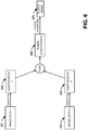
- An example of a wavelet-based image fusion technique is shown in FIG. 6 , where the output of the wavelet-based image fusion technique (e.g., fused image 270) is the L* component.
- fused image 270 high frequency content in the image data from one band of dual-band sensor 12 can be used to strengthen the high frequency content in the image data from the other band of the dual-band sensor 12.
- the corrector 152 eliminates noise
- the process of FIG. 6 should take place after the noise is eliminated in both bands, or else the noise will be transferred from one band to the other.
- the fused image 270 (and thereby the L* component) can emphasize the sharp borders of objects and object components (e.g., military targets) that correspond to abrupt changes in image properties of the dual-band image while de-emphasizing the borders of natural objects (e.g., trees, bushes, grass and the like), which can often reveal important changes in the scene recorded by the dual-band sensor 12.
- object components e.g., military targets
- the abrupt changes can include discontinuities in depth, discontinuities in surface orientation, change in material constitution, change in scene illumination, differences in shadowing, or the like.
- image data 251, 252 from the two bands of the dual-band sensor 12 that have undergone any standardization or noise correction by corrector 152 can be received by the generator 154.
- the generator 154 can perform a domain transformation (transform) on both the image data from the first band (image data 1, e.g., LW data) 251 and image data from the second band (image data 2, e.g., MW data) 252 so that the image data 251, 252 is in a transform domain.
- the transform can be a multi-scale transform technique, such as: a two-dimensional discrete wavelet transform (DWT) or a dual-tree complex wavelet transform (DT-CWT). Other transform techniques can be used.
- One example transform that can be used by the generator 154 is a DWT, which captures the frequency and location properties of the image data 251 and 252.
- the input signal can be decomposed to the approximation signal x k+1 (n) and the detail signal y k+1 (n) by filtering with high pass kernels h k for the approximation signal and g k , for the detail signal, as shown in Equations 4 and 5:
- x k + 1 n h k ⁇ x k 2 n
- y k + 1 n g k ⁇ x k 2 n
- x k is the input signal
- x k+1 is the approximation signal
- y k+1 is the detail signal
- h k and g k are high pass filter kernels.
- any signal x k (n) can be decomposed one level to an approxim
- Another example transform that can be used by the generator 154 is the DT-CWT, which has several advantages compared to the DWT. The advantages relate to increased shift invariance and directional sensitivity. As shown in FIG. 6 , two separate transforms are performed. For each image data 251, 252, within the DT-CWT, two pairs of transform images (where a pair includes real and complex images) are computed, where the pixel values are the wavelet coefficients. The first pair is decomposed in scale by using the even terms of the image, while the second pair is decomposed using the odd terms.
- the generator 154 can generate sets of coefficients (coefficients 1 and coefficients 2) 253, 254 corresponding to the image data 251, 252.
- the generator 154 can fuse the sets of coefficients 253, 254 to form a set of fused coefficients 260.
- the fused coefficients 260 can be used to form the fused image 270 after taking an inverse transform.
- the inverse transform is the inverse of the transform used to transform the image data 251, 251 to the sets of coefficients 253, 254.
- the fused image 270 is a grayscale image that captures the luminescence and brightness of the dual-band image recorded by the dual-band sensor 12. Accordingly, the generator 154 uses the fused image 270 as the L* component.
- the system of FIG. 4 also includes a converter 156 that can convert the placeholder image in the placeholder ⁇ L*, a*, b* ⁇ color space to the visible ⁇ R, G, B ⁇ color space to generate the visible color image.
- G L * ⁇ a * 2 + b * 3
- B L * ⁇ 2 ⁇ b * 3
- the visible color image in the visible ⁇ R, G, B ⁇ color space can be transmitted to display 14 so that the display 14 can display the visible color image (e.g., to a human user).
- the data prepared for display 14 can also facilitate processing of the visible color image according to an artificial intelligence routine.
- the visible color image contains more depth and contrast than images recorded by either of the two bands of the dual-band sensor 12.
- An example of the superiority of the visible color image compared to the dual-band image is illustrated in FIG. 3 .
- the visual color image 106 clearly exhibits more depth and contrast compared to the LW image 102 and the MW image 104.
- the converter 156 can perform additional image processing techniques to emphasize certain features within the visible color image. For example, the converter 156 can further permute and/or invert the color channels to change the appearance of the color image (e.g., to emphasize various features of the color image). Similarly, converter 156 can perform a non-linear mapping of the color image to a different color space to change the character of the resulting image to emphasize features of the color image. For example, the permuting, inverting, or mapping to the different color space can create an image with blue sky and green vegetation, one in which military targets appear more prominent than the rest of the image, or one in which obscuring dust appears as a different color than the rest of the image.
- FIG. 7 a method in accordance with various aspects of the present invention will be better appreciated with reference to FIG. 7 . While, for purposes of simplicity of explanation, the methodology of FIG. 7 is shown and described as executing serially, it is to be understood and appreciated that the present invention is not limited by the illustrated order, as some aspects could, in accordance with the present invention, occur in different orders and/or concurrently with other aspects from that shown and described herein. Moreover, not all illustrated features may be required to implement a methodology in accordance with an aspect of the present invention. It will be appreciated that some or all of each of these methods can be implemented as machine-readable instructions on a non-transitory computer readable medium (e.g., memory 16).
- a non-transitory computer readable medium e.g., memory 16
- FIG. 7 illustrates an example of a method 7 for converting a dual-band image (e.g., the dual-band image 52 from dual-band sensor 12) to a visible color image (e.g., the visible color image 56).
- a dual-band image e.g., the dual-band image 52 from dual-band sensor 12
- a visible color image e.g., the visible color image 56.
- noise is reduced in the dual-band infrared image.
- a dynamic range of a first band of the dual-band infrared image e.g., the LW band
- a dynamic range of a second band of the dual-band infrared image e.g., the MW band
- the dual-band infrared image with reduced noise and standardized dynamic range of the first band and the second band is converted to a placeholder image (e.g., the placeholder image 54) in a placeholder color space (e.g., the placeholder ⁇ L* a* b* ⁇ color space) based on a wavelet-based image fusion technique and an oppositional color processing technique utilized by the human visual system.
- the placeholder image is transformed to a visible color space (e.g., the visible ⁇ R, G, B ⁇ color space) to create the visible color image (e.g., visible color image 56).
Landscapes
- Engineering & Computer Science (AREA)
- Multimedia (AREA)
- Signal Processing (AREA)
- Physics & Mathematics (AREA)
- General Physics & Mathematics (AREA)
- Theoretical Computer Science (AREA)
- Image Processing (AREA)
- Color Television Image Signal Generators (AREA)
Description
- This invention was made with Government support under Contract No. W909MY-06-C-0060. The Government has certain rights in this invention.
- The present application claims priority from
U.S. Patent Application Serial No. 14/056306, filed 17 October 2013 , herein incorporated by reference in its entirety. - The present invention relates generally to converting an image from a dual-band sensor to a visible color image based on wavelet-based image fusion and a characteristic of the human visual system.
- A dual-band Forward Looking Infrared (FLIR) camera employs two different sets of sensing elements to detect infrared radiation. The two types of sensors include a long-wave infrared (LW or LWIR, wavelength 8-12 µm) sensor and a mid-wave infrared (MW or MWIR, wavelength 3-5 µm) sensor. LW images from data generated by the LW sensor are based on emitted energy, while the MW images from data generated by the MW sensor are based on emitted energy plus reflected energy, where reflected energy is prevalent in the daytime. Similar but slightly different monochrome images (the LW image and the MW image) can be constructed from data generated by each of the sensors. However, human viewers may have difficulty combining the two images in their minds to create a combined representation of the two monochrome images that accounts for different phenomenological features that may be embedded within the two bands.
- The LW image and the MW image can be combined into a single image with each pixel having a vector of size two (represented as {LW, MW}). A human can perceive phenomenological features in the combined image mapped to two channels of a color display better than in two separate grayscale images. Even more of the phenomenology is perceivable when features of the combined image are displayed in full visual color, using all three channels (e.g., red channel, green channel, and blue channel) of a color display. Typically, the human visual system can directly perceive images within the visible spectrum, which includes three partially overlapping bands: the red band (R), the green band (G) and the blue band (B), such that each pixel of a visible image is a vector of length three {R, G, B}.
- Tsagaris et al.: "Fusion of visible and infrared imager for night color vision", Displays Devices, Dempa Publications, October 2005 describes a combined approach for fusing night-time infrared with visible imagery is presented in this paper. Night color vision is thus accomplished and the final scene has a natural day-time color appearance. Fusion is based either on non-negative matrix factorization or on a transformation that takes into consideration perceptual attributes. The final obtained color images possess a natural day-time color appearance due to the application of a color transfer technique.
- Kin-Wen Tian: "Novel method on dual-band infrared image fusion for dim small target detection", Optical Engineering, vol. 46, no. 11, November 2007 describes a fractal dimension algorithm that fuses mid-wave and long-wave infrared images and detects targets. Usually, the targets in infrared images are man-made, and their fractal dimensions are different from that of their natural background. In the fractal dimension algorithm, the source images are first decomposed by wavelet transformation. Then in the wavelet transformation domain, fractal dimensions are calculated and fusion rules that merge corresponding sub images of two matching source images are set up, and new sub images are created. Finally, the image is reconstructed by inverse wavelet transformation and a fused image is obtained.
-
US2006/006331 discloses a method for representing the front field of vision from a motor vehicle on a display panel of a display includes sensing, by an infrared camera system, the field of vision and feeding corresponding infrared data to a data processing unit. - One embodiment includes an apparatus associated with a processor that facilitates the execution of machine readable instructions to convert an image from a dual-band sensor to a visible color image. The machine readable instructions can facilitate conversion of the image from the dual-band image sensor to a placeholder image in a placeholder color space. The placeholder color space is established based on wavelet-based image fusion and an oppositional color processing technique used by the human visual system. The machine readable instructions can also facilitate mapping the placeholder image to a visible color space to create the visible color image.
- Another embodiment includes a non-transitory computer-readable storage medium storing instructions executable by an associated processor to perform a method for converting an image from a dual-band sensor to a visible color image. The method includes converting the image from the dual-band sensor to a placeholder image in a placeholder color space. The placeholder color space is established based on wavelet-based image fusion and an oppositional color processing technique used by the human visual system to perceive colors. An aspect of the converting includes reducing redundancy between a first component of the image from the dual-band sensor from a first channel and a second component of the image from the dual-band sensor from a second channel. The method also includes mapping the placeholder image into a visible color space to create the visible color image.
- A further embodiment includes a non-transitory computer-readable device storing executable instructions executable by an associated processor to perform operations that convert a dual-band image to a visible color image. The operations include reducing noise in the dual-band image and standardizing a dynamic range between a first component of the image from the dual-band sensor from a first channel and a dynamic range of a second component of the image from the dual-band sensor from a second channel. The operations also include converting the dual-band image with reduced noise and standardized dynamic range to a placeholder image within a placeholder color space that is established based on wavelet-based image fusion and an oppositional color processing technique used by the human visual system. The operations further include transforming the placeholder to a visible color space to create the visible color image.
-
-
FIG. 1 illustrates an example of a system that converts a dual-band image to a visible color image; -
FIG. 2 illustrates an example of a conversion of an image from a dual-band forward-looking infrared (FLIR) sensor to a visible color image; -
FIG. 3 illustrates an example of a visible color image that can be created from a dual-band infrared image from a FLIR sensor; -
FIG. 4 illustrates an example of a system that can be employed by a processor to convert a dual-band image to a visible color image; -
FIG. 5 illustrates an example of a plot that can be employed in the standardization of the dynamic range of the dual-band image; -
FIG. 6 illustrates an example of a wavelet-based image fusion approach that can be employed in the conversion of the dual-band image data to the placeholder L* space; and -
FIG. 7 illustrates an example of a method for converting a dual-band image to a visible color image. - The present invention relates generally to converting a dual-band image from a dual-band sensor to a three-band visible color image. As used in this application, the term "image" generally refers to image data that can be displayed by a display device. As used in this application, the term "visible color image" refers to an image with a red value, a green value and a blue value at each pixel, where each value is within the dynamic range of a standard display (e.g., 8-bits/pixel per color).
- The conversion of the dual-band image to the visible color image can be accomplished via a process that tightly merges wavelet-based image fusion with strategies inspired by the operation of the human visual system. The dual-band image is first converted to a placeholder image in a simplified placeholder {L*, a*, b*} color space. The term "placeholder," as used in this application, generally refers to an intermediate product and is a synonym for intermediate, temporary, notational, preliminary, and other similar terms. The placeholder {L*, a*, b*} color space, as well at the corresponding placeholder {L*, a*, b*} image, is generally formed at least in part via floating point arithmetic. The L* component of the placeholder {L*, a*, b*} color space is generated by fusing images from the bands of the dual-band image using a wavelet-based approach. The a* component of the placeholder {L*, a*, b*} color space and the b* component of the placeholder {L*, a*, b*} color space are generated according to strategies inspired by the human visual system. The placeholder image is mapped to visible {R, G, B} color space to create the visible color image. The visible color image can be displayed by a display device for visual analysis by a human or the data can be exploited by an automated process that uses artificial intelligence.
- Referring now to
FIG. 1 , illustrated is an example of asystem 1 that converts a dual-band image to a visible color image according to a process that tightly merges a wavelet-based image fusion technique with strategies inspired by the human visual system.System 1 includes at least a sensor 12 (sensor 12 is also referred to herein as "the dual-band sensor 12" or "the dual-band camera 12;" the terms "sensor" and "camera" are used interchangeably herein) and aprocessor 10. Theprocessor 10 receives a dual-band image from dual-band sensor 12 and converts the dual-band image to a placeholder image in a placeholder {L*, a*, b*} color space with an L* component, an a* component and a b* component. Theprocessor 10 forms the L* component by fusing images in the two bands of the dual-band image using a wavelet-based approach. Theprocessor 10 employs strategies inspired by the human visual system to form the a* component and the b* component. Theprocessor 10 maps the placeholder image in the placeholder {L*, a*, b*} color space to visible {R, G, B} color space to generate the visible color image. - The dual-band sensor can refer to a sensor that can collect data in at least two bands of the electromagnetic spectrum to form a dual-band image and/or two separate sensors that each produces a different band of the image. Examples of sensors that can be used to generate one or both bands of the dual-
band sensor 12 include a long-wave forward-looking infrared (FLIR) sensor, a mid-wave FLIR sensor, fully integrated dual-band long-wave/mid-wave FLIR sensor, a short wave infrared sensor, a monochrome visible sensor, a near infrared sensor, an image intensified image sensor, or any other type of dual-band sensor or combination of two sensors imaging in different bands. Post-processing stage(s) of the dual-band image that can facilitate conversion to the visible color image can be performed by a processor within thesensor 12 and/or within aprocessor 10 that is external to thesensor 12. Example post-processing stages include non-uniformity correction, bad pixel correction, and the like. - The
processor 10 is communicatively coupled to thesensor 12 according to a means of communication that enables transfer of image data. Theprocessor 10 can be located in a position that facilitates communication with thesensor 12. For example, theprocessor 10 can be housed within the same assembly as thesensor 12, housed within a processor box adjacent to thesensor 12, housed within a processor box separate from thesensor 12, or associated with a display controller, graphical user interface, or the like. Theprocessor 10 can include, for example, a real-time processor, a signal processor, a single-board computer, or any other type of processor that can facilitate execution of instructions for converting the dual-band image represented by the data to the visible color image. - The
processor 10 can utilize different types of hardware and/or software filters throughout the conversion (e.g., applied to one or more of the dual-band image, the placeholder image, or the visible color image) to control the sharpness and/or the noise characteristics of the visible color image. Examples of filters include a mean filter, a median filter, a low-pass filter, a high-pass filter, an unsharp mask filter, and the like. Moreover, theprocessor 10 can further map the visible color image to a different color space (e.g., to emphasize a feature of the visible color image). -
System 1 optionally can include amemory 16 and/or adisplay 14. Thememory 16 can be communicatively coupled to theprocessor 10 and can store executable instructions that can facilitate the conversion of the dual-band image from thesensor 12 to thevisible color image 12 byprocessor 10. Thedisplay 14 can be communicatively coupled to theprocessor 10 to display the visible color image (e.g., to a human user). The data that is generated fordisplay 14 can also be further processed according to an artificial intelligence routine. Thedisplay 14 can include a computer monitor, a video display, or any other type of monitor that can display a visible color image or a motion picture of the visible color image. The visible color image can be a still image, a motion picture, or any combination of a still image and a motion picture. - An example of the functionality of
processor 10 when the dual-band sensor 12 is a FLIR sensor is illustrated inFIG. 2 .Processor 10 receives a dual-band image 52 from theFLIR sensor 12. The dual-band image 52 includes pixels that are two-dimensional vectors of long-wave data (LW) and mid-wave data (MW), represented as {LW, MW}, where LW and MW are assumed to each contain one integer value per pixel. TheFLIR sensor 12 captures image data within the LW band and the MW band, virtually simultaneously. It is assumed that the dual-band image 12 has been spatially registered (e.g., by sensor design, processing, etc.) on a pixel-by-pixel basis prior to processing by theprocessor 10. Theprocessor 10 converts the dual-band {LW, MW} image to aplaceholder image 54. The placeholder image can be represented as a vector of size three, {L*, a*, b*}. The conversion of the dual-band image 52 to theplaceholder image 54 can be accomplished via floating point arithmetic employing a technique that merges wavelet-based image fusion with oppositional color processing techniques used by the human visual system. - The
placeholder image 54 is within a placeholder {L*, a*, b*} color space that includes an L* component, an a* component and a b* component. Theprocessor 10 generates the L* component according to a wavelet-based image fusion approach that fuses the LW component of the dual-band image and the MW component of the dual-band image. Theprocessor 10 generates the a* component and the b* component according to oppositional color processing strategies inspired by the human visual system according to the LW component of the dual-band image, the MW component of the dual-band image, and a function of the LW component of the dual-band image and the MW component of the dual-band image. - The
processor 10 generates thevisible color image 56 from theplaceholder image 54. As an example, theprocessor 10 can map theplaceholder image 54 in the placeholder {L*, a*, b*} space to thevisible color image 56 within the red band, the green band and the blue band, which is denoted as a vector of size three, {R, G, B}. Thevisible color image 56 can be displayed by a display device (e.g., thedisplay device 14, such as a computer monitor) so that features can be detected by human perception. The data related to the visible color image 56 (e.g., in floating point or fixed point form) can be further processed according to an artificial intelligence routine. Thevisible color image 56 can be provided in integer format, one integer per color component per pixel. The input (e.g., dual-band image 52) and output (e.g., visible color image 56) images can contain the same number of pixels in the same height to width ratio. The output (e.g., visible color image 56) can also be reformatted to meet the requirements of a particular display. - An example of the conversion of an
LW image 102 and anMW image 104 from a dual-band FLIR sensor to avisible color image 106 is shown inFIG. 3 . The processor converts theLW image 102 and theMW image 104 to the placeholder image in the placeholder {L*, a*, b*} color space based on wavelet-based image fusion and an oppositional color processing technique used by the human visual system. Theprocessor 10 then maps the placeholder image to visible {R, G, B} color space to generate thevisible color image 106. As evident inFIG. 3 , thevisible color image 106 contains more depth and contrast than either theLW image 102 or theMW image 104. - Referring now to
FIG. 4 , illustrated is a system that can be executed by theprocessor 10 to facilitate the conversion of a dual-band image recorded by a dual-band sensor 12 to a visible color image that can be displayed by adisplay device 14. Instructions that facilitate the operation of the system can be stored in thememory 16 that is coupled to the processor. As shown inFIG. 4 , the system includes at least acorrector 152, agenerator 154, and aconverter 156. - The
corrector 152 receives image data representing the dual-band image from thesensor 12. The image data includes data captured in the first band and data captured in the second band of the dual-band sensor 12. The data captured in the first band and/or data captured in the second band of the dual-band sensor 12 can include anomalies, e.g., abnormally bright pixels or abnormally dark pixels. Thecorrector 152 can eliminate these anomalies via standardization of the dynamic range of the data captured in the first band and/or the data captured in the second band of the dual-band sensor 12. To eliminate the anomalies, thecorrector 152 can standardize the dynamic range of data captured in the first band and data captured in the second band of the dual-band sensor 12. - During the standardization, the
corrector 152 checks the data captured in the first band and/or the data captured in the second band of the dual-band sensor 12 for anomalies. For example, thecorrector 152 can check the data by examining the histograms of brightness levels related to the data. Assuming that higher gray levels correspond to hotter areas in the scene, certain anomalies often have a much higher gray level than the rest of the data within the band, which is represented as a gap in the right tail of the histogram. These types of anomalies correspond to either the highly non-Gaussian nature of some infrared images or occasionally to uncorrected image errors. Thecorrector 152 detects the gap and/or the anomalies in the right tail of the histogram and flags the data as an anomaly for standardization. - When the
corrector 152 detects an anomaly, one way the anomaly can be corrected is through a Lin/Log transformation. An example of the Lin/Log transformation is represented mathematically in Equation 1:
- An example of a plot that can be used for selection of the X0 value in the Lin/Log transform is shown in
FIG. 5 , where X is the input gray level and Y is the output gray level. Theinflection point 208 can be chosen to prevent a large portion of the dynamic range of an image from being used for just a small section of the image. The X-value of theinflection point 208 can be used as the X0 value. Theinflection point 208 can be chosen based on factors including, but not limited to: a number of standard deviations above the image mean, a limitation of the number of pixels subject to the transform, a start of a gap at the right tail of a histogram of grayscale values, or another feature that indicates an anomaly. - Additionally or alternatively, the
corrector 152 can reduce noise or non-uniformity within the dual-band image. The system can operate without thecorrector 152 reducing the noise in the dual-band image, but the system can produce a better visible color image when the dual-band image exhibits low noise. The noise that can be reduced in the dual-band image bycorrector 152 can include: random spatial-temporal noise, temporal row noise, temporal column noise, random spatial noise, fixed row noise, fixed column noise, frame-to-frame noise, image brightness flicker, thermal vignetting, periodic noise within an image, and the like.Corrector 152 can employ standard statistical signal processing or image processing techniques to reduce the different types of noise and/or non-uniformity. Some of the noise types can also be corrected within the dual-band sensor 12. For example, the dual-band sensor 12 can employ a thermal reference correction or a scene-based non-uniformity correction to correct for at least a portion of the noise within the dual-band image. - Referring back to
FIG. 4 , thegenerator 154 can generate the placeholder image within the placeholder {L*, a*, b*} three-dimensional color space. Thegenerator 154 can generate the L* component of the placeholder image by fusing each dimension of the dual-band image according to a wavelet-based approach. Thegenerator 154 can generate the a* component and the b* component according to strategies inspired by the human visual system. Thegenerator 154 can further expand the dynamic range of the a* component and/or the b* component to reduce the redundancy between the images corresponding to each of the two bands of the dual-band image. - The
generator 154 can generate the a* component and the b* component according to strategies inspired by the human visual system. The retina of the human visual system includes rods, which generally perceive a grayscale image, and cones, which generally perceive a color image. The cones can perceive the red band, the green band, and the blue band of the visible portion of the electromagnetic spectrum. The response of the cones to the red band and the green band is highly overlapping, yet humans perceive red and green as distinct colors due to conversion of the incoming image into an opponency space (referred to as oppositional color processing). The placeholder {L*, a*, b*} space used in the conversion of a dual-band image to a visible color image mimics the oppositional color processing of the human visual system. L*, a* and b* are the orthogonal axes of a three-dimensional coordinate system, where L* represents the luminance or brightness axis, a* represents the Red/Green axis, and b* represents the Blue/Yellow axis. - The
generator 154 can convert the dual-band image recorded by the dual-band sensor 12 into the three visible color channels (Red, Green, Blue) and then convert the RGB image into the placeholder {L*, a*, b*} space. In the example where the dual-band image {LW, MW} is taken by a FLIR sensor, thegenerator 154 converts the dual-band {LW, MW} image to a temporary {R, G, B} visible color space as follows in Equation 2:
- The
generator 154 then converts the temporary {R, G, B} visible color space to the a* and b* components of the placeholder {L*, a*, b*} space. It will be understood by a person having ordinary skill in the art that there are alternative formulations of placeholder color spaces that can be utilized as the placeholder {L*, a*, b*} color space by thegenerator 154. The formulation of the placeholder {L*, a*, b*} color space as described herein is but one of many possible examples. - In the placeholder {L*, a*, b*} color space, the a* component is a function of R and G. The b* component is a function of B, R and G. An example of calculation of the a* component and the b* component is shown in Equation 3:

Thegenerator 154 can expand the dynamic ranges of the a* and b* channels to reduce redundancy between the LW and MW images. As an example, the expansion can be performed by stretching the histogram of a* and b* image values (by an empirically determined fixed amount) about their respective image mean value. - The
generator 154 can generate the L* component wavelet-based image fusion techniques. An example of a wavelet-based image fusion technique is shown inFIG. 6 , where the output of the wavelet-based image fusion technique (e.g., fused image 270) is the L* component. In the fusedimage 270, high frequency content in the image data from one band of dual-band sensor 12 can be used to strengthen the high frequency content in the image data from the other band of the dual-band sensor 12. In the case where thecorrector 152 eliminates noise, the process ofFIG. 6 should take place after the noise is eliminated in both bands, or else the noise will be transferred from one band to the other. - The fused image 270 (and thereby the L* component) can emphasize the sharp borders of objects and object components (e.g., military targets) that correspond to abrupt changes in image properties of the dual-band image while de-emphasizing the borders of natural objects (e.g., trees, bushes, grass and the like), which can often reveal important changes in the scene recorded by the dual-
band sensor 12. The abrupt changes can include discontinuities in depth, discontinuities in surface orientation, change in material constitution, change in scene illumination, differences in shadowing, or the like. - As illustrated in
FIG. 6 ,image data band sensor 12 that have undergone any standardization or noise correction bycorrector 152 can be received by thegenerator 154. Thegenerator 154 can perform a domain transformation (transform) on both the image data from the first band (image data 1, e.g., LW data) 251 and image data from the second band (image data 2, e.g., MW data) 252 so that theimage data - One example transform that can be used by the
generator 154 is a DWT, which captures the frequency and location properties of theimage data FIG. 6 , two separate transforms are performed. For each channel of the dual-mode image The input signal can be decomposed to the approximation signal xk+1(n) and the detail signal yk+1(n) by filtering with high pass kernels hk for the approximation signal and gk, for the detail signal, as shown in Equations 4 and 5:

- Another example transform that can be used by the
generator 154 is the DT-CWT, which has several advantages compared to the DWT. The advantages relate to increased shift invariance and directional sensitivity. As shown inFIG. 6 , two separate transforms are performed. For eachimage data - After the transformation, the
generator 154 can generate sets of coefficients (coefficients 1 and coefficients 2) 253, 254 corresponding to theimage data generator 154 can fuse the sets ofcoefficients coefficients 260. The fusedcoefficients 260 can be used to form the fusedimage 270 after taking an inverse transform. The inverse transform is the inverse of the transform used to transform theimage data coefficients image 270 is a grayscale image that captures the luminescence and brightness of the dual-band image recorded by the dual-band sensor 12. Accordingly, thegenerator 154 uses the fusedimage 270 as the L* component. - An alternate approach that the
generator 154 can use to generate the L* component can be employed when processing resources ofprocessor 10 are limited. In the alternate approach, only a single wavelet frequency is utilized, and frequency is a function of range. The L* value at a pixel in the case where the dual-band sensor 12 is a FLIR sensor is computed according the alternate approach, shown in Equation 6:


- Ψ r = Ψ r(R) is a two - dimensional Gaussian blur function of radius r,
- R = range in meters, and
- LW and MW images are pre - normalized in mean and variance.
- The system of
FIG. 4 also includes aconverter 156 that can convert the placeholder image in the placeholder {L*, a*, b*} color space to the visible {R, G, B} color space to generate the visible color image. This conversion can be accomplished according toEquation 7, where each component of the visual {R, G, B} color space is based on components of the placeholder image:
display 14 can display the visible color image (e.g., to a human user). The data prepared fordisplay 14 can also facilitate processing of the visible color image according to an artificial intelligence routine. The visible color image contains more depth and contrast than images recorded by either of the two bands of the dual-band sensor 12. An example of the superiority of the visible color image compared to the dual-band image is illustrated inFIG. 3 . InFIG. 3 , to the human observer, thevisual color image 106 clearly exhibits more depth and contrast compared to theLW image 102 and theMW image 104. - Referring back to
FIG. 4 , theconverter 156 can perform additional image processing techniques to emphasize certain features within the visible color image. For example, theconverter 156 can further permute and/or invert the color channels to change the appearance of the color image (e.g., to emphasize various features of the color image). Similarly,converter 156 can perform a non-linear mapping of the color image to a different color space to change the character of the resulting image to emphasize features of the color image. For example, the permuting, inverting, or mapping to the different color space can create an image with blue sky and green vegetation, one in which military targets appear more prominent than the rest of the image, or one in which obscuring dust appears as a different color than the rest of the image. - In view of the foregoing structural and functional features described above, a method in accordance with various aspects of the present invention will be better appreciated with reference to
FIG. 7 . While, for purposes of simplicity of explanation, the methodology ofFIG. 7 is shown and described as executing serially, it is to be understood and appreciated that the present invention is not limited by the illustrated order, as some aspects could, in accordance with the present invention, occur in different orders and/or concurrently with other aspects from that shown and described herein. Moreover, not all illustrated features may be required to implement a methodology in accordance with an aspect of the present invention. It will be appreciated that some or all of each of these methods can be implemented as machine-readable instructions on a non-transitory computer readable medium (e.g., memory 16). -
FIG. 7 illustrates an example of amethod 7 for converting a dual-band image (e.g., the dual-band image 52 from dual-band sensor 12) to a visible color image (e.g., the visible color image 56). At 350, noise is reduced in the dual-band infrared image. At 352, a dynamic range of a first band of the dual-band infrared image (e.g., the LW band) and a dynamic range of a second band of the dual-band infrared image (e.g., the MW band) are standardized (e.g., via the corrector 152). At 354, the dual-band infrared image with reduced noise and standardized dynamic range of the first band and the second band is converted to a placeholder image (e.g., the placeholder image 54) in a placeholder color space (e.g., the placeholder {L* a* b*} color space) based on a wavelet-based image fusion technique and an oppositional color processing technique utilized by the human visual system. At 356, the placeholder image is transformed to a visible color space (e.g., the visible {R, G, B} color space) to create the visible color image (e.g., visible color image 56).
The alternate approach generates the L* component without consuming a prohibitive amount of processor resources when the processing resources of
Claims (15)
- An apparatus, comprising:a non-transitory memory (16) storing machine-readable instructions; anda processor (10);characterized in that the processor facilitates the execution of machine-readable instructions to:fuse different bands of the dual-band image sensor (12) data using wavelet-based image fusion to generate the L* component of an {L*, a*, b*} color space placeholder image (54);generate the a* and b* components of the placeholder image (54) by:generating an {R, G, B} visible color space temporary image having red, green, and blue channels, wherein the red channel of the temporary image is created from one band of the dual-band image sensor (12), the green channel of the temporary image is created from the other band of the dual-band image sensor (12), and the blue channel of the temporary image is created from either the product of the two bands of the dual-band image sensor (12) or the ratio of the two bands of the dual-band image sensor (12);generating the a* component of the placeholder image (54) as a function of the red and green channels of the temporary image; andgenerating the b* component of the placeholder image (54) as a function of the red, green, and blue channels of the temporary image; andconverting the placeholder image to an {R, G, B} visible color space output image (56) having red, green, and blue channels, wherein the red channel of the output image (56) is created as the sum of the L* component and the sum of 1/2 times the a* component and 1/3 times the b* component, the green channel of the output image (56) is created as the difference between the L* component and the sum of 1/2 times the a* component and 1/3 times the b* component, and the blue channel of the output image (56) is created as the difference between the L* component and 2/3 times the b* component.
- The apparatus of claim 1, wherein the dual-band image sensor (12) is a dual-band forward looking infrared sensor or at least two of a long wave infrared sensor, a mid wave infrared sensor, a short wave infrared sensor, a monochrome visible sensor, a near infrared sensor, or an image intensified image sensor.
- The apparatus of claim 1, wherein:the image (52) from the dual-band sensor (12) comprises long-wave data and mid-wave data; andthe a* and b* components of the placeholder image (54) are further generated by expanding the dynamic ranges of the a* and b* channels to reduce redundancy between the two bands of the dual-band image sensor (12), such that data within the placeholder image (54) exhibits a decreased redundancy relative to a pairing of the long-wave data and the mid-wave data.
- The apparatus of claim 1, wherein:the image (52) from the dual-band sensor (12) comprises long-wave data and mid-wave data;the red channel of the temporary image comprises the long-wave data;the green channel of the temporary image comprises the mid-wave data; andthe blue channel of the temporary image comprises data that represents either the product or the ratio of the long-wave data and the mid-wave data.
- The apparatus of claim 3, wherein the expansion of the dynamic ranges of the a* and b* channels is performed by stretching the histogram of a* and b* image values about their respective image mean values.
- The apparatus of claim 1, wherein the L* component of the placeholder image (54) is generated using only a single wavelet frequency.
- The apparatus of claim 6, wherein the single wavelet frequency is a function of range in units of distance.
- The apparatus of claim 1, wherein the processor (10) further facilitates the execution of the machine-readable instructions to apply a mean filter, a median filter, a high-pass filter, a low-pass filter, or an unsharp-mask filter to at least one of the image (52) from the dual-band sensor (12), the placeholder image (54), or the visible color image (56).
- A non-transitory computer-readable storage medium storing instructions executable by an associated processor (10) to perform a method for converting a dual-band image (52) to a visible color image (56), the method being characterized in that it comprises the steps of:fusing different bands of the dual-band image (52) using wavelet-based image fusion to generate the L* component of an {L*, a*, b*} color space placeholder image (54);generating the a* and b* components of the placeholder image (54) by:generating an {R, G, B} visible color space temporary image having red, green, and blue channels, wherein the red channel of the temporary image is created from one band of the dual-band image sensor (12), the green channel of the temporary image is created from the other band of the dual-band image sensor (12), and the blue channel of the temporary image is created from either the product of the two bands of the dual-band image sensor (12) or the ratio of the two bands of the dual-band image sensor (12);generating the a* component of the placeholder image (54) as a function of the red and green channels of the temporary image; andgenerating the b* component of the placeholder image (54) as a function of the red, green, and blue channels of the temporary image; andconverting the placeholder image (54) to an {R, G, B} visible color space output image (56) having red, green, and blue channels, wherein the red channel of the output image (56) is created as the sum of the L* component and the sum of 1/2 times the a* component and 1/3 times the b* component, the green channel of the output image (56) is created as the difference between the L* component and the sum of 1/2 times the a* component and 1/3 times the b* component, and the blue channel of the output image (56) is created as the difference between the L* component and 2/3 times the b* component; andemphasizing a feature of the output image (56) based on the converting the placeholder image (54) to the output image (56).
- The non-transitory computer-readable storage medium of claim 9, wherein:
the first channel of the dual-band image (52) comprises long-wave data and the second channel of the dual-band image (52) comprises mid-wave data. - The non-transitory computer-readable storage medium of claim 10, wherein
the red channel of the temporary image comprises the long-wave infrared data;
the green channel of the temporary image comprises the mid-wave infrared data; and
the blue channel of the temporary image comprises data that represents either the product or the ratio of the long-wave infrared data and the mid-wave infrared data. - The non-transitory computer-readable storage medium of claim 11, wherein the a* and b* components of the placeholder image (54) are further generated by expanding the dynamic ranges of the a* and b* channels to reduce redundancy between the two bands of the dual-band image sensor (12), such that data within the placeholder image (54) exhibits a decreased redundancy relative to a pairing of the long-wave infrared data and the mid-wave infrared data.
- The non-transitory computer-readable storage medium of claim 9, wherein the L* component of the placeholder image (54) is generated using only a single wavelet frequency, the frequency being a function of range in units of distance.
- The non-transitory computer-readable storage medium of claim 9, the method further comprising, prior to the fusing of the different bands of the dual-band image (52):applying a filtering algorithm to reduce noise in the dual-band infrared image (52); andstandardizing a dynamic range of a first band of the dual-band infrared image (52);and a dynamic range of a second band of the dual-band infrared image (52) to facilitate the fusion of the different bands of the dual-band image (52).
- The non-transitory computer-readable storage medium of claim 14, wherein:the first band comprises long-wave data; andthe second band comprises mid-wave data.
Applications Claiming Priority (2)
| Application Number | Priority Date | Filing Date | Title |
|---|---|---|---|
| US14/056,306 US9544562B2 (en) | 2013-10-17 | 2013-10-17 | Converting an image from a dual-band sensor to a visible color image |
| PCT/US2014/059469 WO2015057425A1 (en) | 2013-10-17 | 2014-10-07 | Converting an image from a dual-band sensor to a visible color image |
Publications (2)
| Publication Number | Publication Date |
|---|---|
| EP3058549A1 EP3058549A1 (en) | 2016-08-24 |
| EP3058549B1 true EP3058549B1 (en) | 2019-02-27 |
Family
ID=51790879
Family Applications (1)
| Application Number | Title | Priority Date | Filing Date |
|---|---|---|---|
| EP14787350.9A Active EP3058549B1 (en) | 2013-10-17 | 2014-10-07 | Converting an image from a dual-band sensor to a visible color image |
Country Status (5)
| Country | Link |
|---|---|
| US (1) | US9544562B2 (en) |
| EP (1) | EP3058549B1 (en) |
| JP (1) | JP6290392B2 (en) |
| IL (1) | IL245012B (en) |
| WO (1) | WO2015057425A1 (en) |
Families Citing this family (10)
| Publication number | Priority date | Publication date | Assignee | Title |
|---|---|---|---|---|
| US9756263B2 (en) * | 2014-05-01 | 2017-09-05 | Rebellion Photonics, Inc. | Mobile gas and chemical imaging camera |
| JP6394338B2 (en) * | 2014-12-04 | 2018-09-26 | ソニー株式会社 | Image processing apparatus, image processing method, and imaging system |
| JP2017099616A (en) * | 2015-12-01 | 2017-06-08 | ソニー株式会社 | Surgical control device, surgical control method and program, and surgical system |
| CN105844674B (en) * | 2016-03-02 | 2018-11-30 | 淮阴师范学院 | Color Image Fusion system and method based on Three-ary Number wavelet transformation |
| KR101795728B1 (en) * | 2016-05-23 | 2017-11-09 | 한국과학기술연구원 | Measuring and Processing System for Infrared Image |
| CN106530277B (en) * | 2016-10-13 | 2019-09-10 | 中国人民解放军理工大学 | A kind of image interfusion method based on small echo directional correlation coefficient |
| US11113791B2 (en) * | 2017-01-03 | 2021-09-07 | Flir Systems, Inc. | Image noise reduction using spectral transforms |
| CN107909112B (en) * | 2017-11-27 | 2020-08-18 | 中北大学 | Fusion method for combination of infrared light intensity and polarization image multi-class variables |
| CN110246108B (en) * | 2018-11-21 | 2023-06-20 | 浙江大华技术股份有限公司 | Image processing method, device and computer readable storage medium |
| US11049226B1 (en) * | 2019-04-23 | 2021-06-29 | Bae Systems Information And Electronics Systems Integration Inc. | Median based frequency separation local area contrast enhancement |
Family Cites Families (17)
| Publication number | Priority date | Publication date | Assignee | Title |
|---|---|---|---|---|
| JP2964492B2 (en) * | 1989-08-15 | 1999-10-18 | ソニー株式会社 | Image processing apparatus and image processing method |
| JP3256982B2 (en) * | 1991-05-14 | 2002-02-18 | 富士ゼロックス株式会社 | Image processing device |
| JP2004165800A (en) * | 2002-11-11 | 2004-06-10 | Canon Inc | Image processing device |
| JP2004247789A (en) * | 2003-02-10 | 2004-09-02 | Konica Minolta Holdings Inc | Image reading processing apparatus, image reading processing method, and recording medium |
| JP2004350171A (en) * | 2003-05-26 | 2004-12-09 | Noritsu Koki Co Ltd | Photographic image processing method and apparatus |
| EP1538826A3 (en) * | 2003-12-05 | 2007-03-07 | Samsung Electronics Co., Ltd. | Color transformation method and apparatus |
| JP4363207B2 (en) * | 2004-02-05 | 2009-11-11 | 住友電気工業株式会社 | Image processing method, image processing system, and image processing apparatus |
| DE102004033625B4 (en) | 2004-07-12 | 2008-12-24 | Continental Automotive Gmbh | Method for displaying the particular front field of view from a motor vehicle |
| JP4295709B2 (en) * | 2004-10-14 | 2009-07-15 | 富士フイルム株式会社 | Imaging apparatus, image processing apparatus, and image processing method |
| EP1887785A1 (en) * | 2006-08-04 | 2008-02-13 | Nederlandse Organisatie voor Toegepast-Natuuurwetenschappelijk Onderzoek TNO | Method and system for converting at least one first-spectrum image into a second-spectrum image |
| JP5343339B2 (en) * | 2007-10-04 | 2013-11-13 | セイコーエプソン株式会社 | Image processing apparatus, image processing method, and computer program |
| WO2009051900A2 (en) * | 2007-10-17 | 2009-04-23 | Exxonmobil Upstream Research Company | Method to adapt a template dataset to a target dataset by using curvelet representations |
| US9064315B2 (en) * | 2011-09-28 | 2015-06-23 | The United States Of America As Represented By The Secretary Of The Army | System and processor implemented method for improved image quality and enhancement |
| US9883833B2 (en) * | 2008-05-13 | 2018-02-06 | Spectral Image, Inc. | Systems and methods for hyperspectral medical imaging using real-time projection of spectral information |
| US9255914B2 (en) * | 2009-08-13 | 2016-02-09 | Kabushiki Kaisha Toshiba | Ultrasonic diagnosis apparatus and program |
| WO2013090922A1 (en) * | 2011-12-16 | 2013-06-20 | Tenebraex Corporation | Systems and methods for creating full-color image in low light |
| EP2994094B1 (en) * | 2013-05-09 | 2020-06-17 | The Procter and Gamble Company | Hair care conditioning composition comprising histidine |
-
2013
- 2013-10-17 US US14/056,306 patent/US9544562B2/en active Active
-
2014
- 2014-10-07 EP EP14787350.9A patent/EP3058549B1/en active Active
- 2014-10-07 JP JP2016524128A patent/JP6290392B2/en active Active
- 2014-10-07 WO PCT/US2014/059469 patent/WO2015057425A1/en not_active Ceased
-
2016
- 2016-04-10 IL IL245012A patent/IL245012B/en active IP Right Grant
Non-Patent Citations (1)
| Title |
|---|
| None * |
Also Published As
| Publication number | Publication date |
|---|---|
| WO2015057425A1 (en) | 2015-04-23 |
| JP6290392B2 (en) | 2018-03-07 |
| US20150288941A1 (en) | 2015-10-08 |
| JP2016535485A (en) | 2016-11-10 |
| US9544562B2 (en) | 2017-01-10 |
| IL245012B (en) | 2020-03-31 |
| IL245012A0 (en) | 2016-05-31 |
| EP3058549A1 (en) | 2016-08-24 |
Similar Documents
| Publication | Publication Date | Title |
|---|---|---|
| US9544562B2 (en) | Converting an image from a dual-band sensor to a visible color image | |
| EP3800616B1 (en) | Image processing method and device | |
| US8755597B1 (en) | Smart fusion of visible and infrared image data | |
| KR100944462B1 (en) | Satellite image fusion method and system | |
| CN112801927B (en) | An infrared and visible light image fusion method based on three-scale decomposition | |
| CN102547063B (en) | Natural sense color fusion method based on color contrast enhancement | |
| CN111062905A (en) | An infrared and visible light fusion method based on saliency map enhancement | |
| US20090175535A1 (en) | Improved processing of multi-color images for detection and classification | |
| EP3948766B1 (en) | Systems and methods for image processing | |
| US20230351569A1 (en) | Conjugate image for color and near-infrared image fusion | |
| CN111179168B (en) | A vehicle-mounted 360-degree panoramic view monitoring system and method | |
| CN106952246A (en) | The visible ray infrared image enhancement Color Fusion of view-based access control model attention characteristic | |
| JP2014241584A (en) | Image processing method and image processing system | |
| DE102011105628A1 (en) | System and method for supporting a driver's view | |
| CN107240081A (en) | The denoising of night scene image and enhancing processing method | |
| EP4030338A1 (en) | Obstacle detection method, apparatus and device, and medium | |
| US8824828B1 (en) | Thermal V-curve for fusion image declutter | |
| CN103546730A (en) | Method for enhancing light sensitivities of images on basis of multiple cameras | |
| KR20210096925A (en) | Flexible Color Correction Method for Massive Aerial Orthoimages | |
| KR20210096926A (en) | Color Correction Method Using Low Resolution Color Image Of Large-capacity Aerial Orthoimage | |
| EP4430556B1 (en) | Temporal filtering weight computation | |
| US10621709B1 (en) | Enhancing image quality based on characteristics of a reference region of interest | |
| JP5718138B2 (en) | Image signal processing apparatus and program | |
| Miao et al. | A dual branch network combining detail information and color feature for remote sensing image dehazing | |
| CN110580684A (en) | image enhancement method based on black-white-color binocular camera |
Legal Events
| Date | Code | Title | Description |
|---|---|---|---|
| PUAI | Public reference made under article 153(3) epc to a published international application that has entered the european phase |
Free format text: ORIGINAL CODE: 0009012 |
|
| 17P | Request for examination filed |
Effective date: 20160413 |
|
| AK | Designated contracting states |
Kind code of ref document: A1 Designated state(s): AL AT BE BG CH CY CZ DE DK EE ES FI FR GB GR HR HU IE IS IT LI LT LU LV MC MK MT NL NO PL PT RO RS SE SI SK SM TR |
|
| AX | Request for extension of the european patent |
Extension state: BA ME |
|
| DAX | Request for extension of the european patent (deleted) | ||
| GRAP | Despatch of communication of intention to grant a patent |
Free format text: ORIGINAL CODE: EPIDOSNIGR1 |
|
| STAA | Information on the status of an ep patent application or granted ep patent |
Free format text: STATUS: GRANT OF PATENT IS INTENDED |
|
| RIC1 | Information provided on ipc code assigned before grant |
Ipc: H04N 9/77 20060101ALI20180828BHEP Ipc: H04N 5/33 20060101ALI20180828BHEP Ipc: G06T 5/50 20060101AFI20180828BHEP |
|
| INTG | Intention to grant announced |
Effective date: 20180914 |
|
| GRAS | Grant fee paid |
Free format text: ORIGINAL CODE: EPIDOSNIGR3 |
|
| GRAA | (expected) grant |
Free format text: ORIGINAL CODE: 0009210 |
|
| STAA | Information on the status of an ep patent application or granted ep patent |
Free format text: STATUS: THE PATENT HAS BEEN GRANTED |
|
| AK | Designated contracting states |
Kind code of ref document: B1 Designated state(s): AL AT BE BG CH CY CZ DE DK EE ES FI FR GB GR HR HU IE IS IT LI LT LU LV MC MK MT NL NO PL PT RO RS SE SI SK SM TR |
|
| REG | Reference to a national code |
Ref country code: GB Ref legal event code: FG4D |
|
| REG | Reference to a national code |
Ref country code: CH Ref legal event code: EP |
|
| REG | Reference to a national code |
Ref country code: AT Ref legal event code: REF Ref document number: 1102451 Country of ref document: AT Kind code of ref document: T Effective date: 20190315 |
|
| REG | Reference to a national code |
Ref country code: IE Ref legal event code: FG4D |
|
| REG | Reference to a national code |
Ref country code: DE Ref legal event code: R096 Ref document number: 602014041909 Country of ref document: DE |
|
| REG | Reference to a national code |
Ref country code: NL Ref legal event code: MP Effective date: 20190227 |
|
| REG | Reference to a national code |
Ref country code: LT Ref legal event code: MG4D |
|
| PG25 | Lapsed in a contracting state [announced via postgrant information from national office to epo] |
Ref country code: PT Free format text: LAPSE BECAUSE OF FAILURE TO SUBMIT A TRANSLATION OF THE DESCRIPTION OR TO PAY THE FEE WITHIN THE PRESCRIBED TIME-LIMIT Effective date: 20190627 Ref country code: NL Free format text: LAPSE BECAUSE OF FAILURE TO SUBMIT A TRANSLATION OF THE DESCRIPTION OR TO PAY THE FEE WITHIN THE PRESCRIBED TIME-LIMIT Effective date: 20190227 Ref country code: FI Free format text: LAPSE BECAUSE OF FAILURE TO SUBMIT A TRANSLATION OF THE DESCRIPTION OR TO PAY THE FEE WITHIN THE PRESCRIBED TIME-LIMIT Effective date: 20190227 Ref country code: LT Free format text: LAPSE BECAUSE OF FAILURE TO SUBMIT A TRANSLATION OF THE DESCRIPTION OR TO PAY THE FEE WITHIN THE PRESCRIBED TIME-LIMIT Effective date: 20190227 Ref country code: SE Free format text: LAPSE BECAUSE OF FAILURE TO SUBMIT A TRANSLATION OF THE DESCRIPTION OR TO PAY THE FEE WITHIN THE PRESCRIBED TIME-LIMIT Effective date: 20190227 Ref country code: NO Free format text: LAPSE BECAUSE OF FAILURE TO SUBMIT A TRANSLATION OF THE DESCRIPTION OR TO PAY THE FEE WITHIN THE PRESCRIBED TIME-LIMIT Effective date: 20190527 |
|
| PG25 | Lapsed in a contracting state [announced via postgrant information from national office to epo] |
Ref country code: BG Free format text: LAPSE BECAUSE OF FAILURE TO SUBMIT A TRANSLATION OF THE DESCRIPTION OR TO PAY THE FEE WITHIN THE PRESCRIBED TIME-LIMIT Effective date: 20190527 Ref country code: GR Free format text: LAPSE BECAUSE OF FAILURE TO SUBMIT A TRANSLATION OF THE DESCRIPTION OR TO PAY THE FEE WITHIN THE PRESCRIBED TIME-LIMIT Effective date: 20190528 Ref country code: RS Free format text: LAPSE BECAUSE OF FAILURE TO SUBMIT A TRANSLATION OF THE DESCRIPTION OR TO PAY THE FEE WITHIN THE PRESCRIBED TIME-LIMIT Effective date: 20190227 Ref country code: HR Free format text: LAPSE BECAUSE OF FAILURE TO SUBMIT A TRANSLATION OF THE DESCRIPTION OR TO PAY THE FEE WITHIN THE PRESCRIBED TIME-LIMIT Effective date: 20190227 Ref country code: IS Free format text: LAPSE BECAUSE OF FAILURE TO SUBMIT A TRANSLATION OF THE DESCRIPTION OR TO PAY THE FEE WITHIN THE PRESCRIBED TIME-LIMIT Effective date: 20190627 Ref country code: LV Free format text: LAPSE BECAUSE OF FAILURE TO SUBMIT A TRANSLATION OF THE DESCRIPTION OR TO PAY THE FEE WITHIN THE PRESCRIBED TIME-LIMIT Effective date: 20190227 |
|
| REG | Reference to a national code |
Ref country code: AT Ref legal event code: MK05 Ref document number: 1102451 Country of ref document: AT Kind code of ref document: T Effective date: 20190227 |
|
| PG25 | Lapsed in a contracting state [announced via postgrant information from national office to epo] |
Ref country code: IT Free format text: LAPSE BECAUSE OF FAILURE TO SUBMIT A TRANSLATION OF THE DESCRIPTION OR TO PAY THE FEE WITHIN THE PRESCRIBED TIME-LIMIT Effective date: 20190227 Ref country code: RO Free format text: LAPSE BECAUSE OF FAILURE TO SUBMIT A TRANSLATION OF THE DESCRIPTION OR TO PAY THE FEE WITHIN THE PRESCRIBED TIME-LIMIT Effective date: 20190227 Ref country code: CZ Free format text: LAPSE BECAUSE OF FAILURE TO SUBMIT A TRANSLATION OF THE DESCRIPTION OR TO PAY THE FEE WITHIN THE PRESCRIBED TIME-LIMIT Effective date: 20190227 Ref country code: SK Free format text: LAPSE BECAUSE OF FAILURE TO SUBMIT A TRANSLATION OF THE DESCRIPTION OR TO PAY THE FEE WITHIN THE PRESCRIBED TIME-LIMIT Effective date: 20190227 Ref country code: ES Free format text: LAPSE BECAUSE OF FAILURE TO SUBMIT A TRANSLATION OF THE DESCRIPTION OR TO PAY THE FEE WITHIN THE PRESCRIBED TIME-LIMIT Effective date: 20190227 Ref country code: AL Free format text: LAPSE BECAUSE OF FAILURE TO SUBMIT A TRANSLATION OF THE DESCRIPTION OR TO PAY THE FEE WITHIN THE PRESCRIBED TIME-LIMIT Effective date: 20190227 Ref country code: EE Free format text: LAPSE BECAUSE OF FAILURE TO SUBMIT A TRANSLATION OF THE DESCRIPTION OR TO PAY THE FEE WITHIN THE PRESCRIBED TIME-LIMIT Effective date: 20190227 Ref country code: DK Free format text: LAPSE BECAUSE OF FAILURE TO SUBMIT A TRANSLATION OF THE DESCRIPTION OR TO PAY THE FEE WITHIN THE PRESCRIBED TIME-LIMIT Effective date: 20190227 |
|
| REG | Reference to a national code |
Ref country code: DE Ref legal event code: R097 Ref document number: 602014041909 Country of ref document: DE |
|
| PG25 | Lapsed in a contracting state [announced via postgrant information from national office to epo] |
Ref country code: SM Free format text: LAPSE BECAUSE OF FAILURE TO SUBMIT A TRANSLATION OF THE DESCRIPTION OR TO PAY THE FEE WITHIN THE PRESCRIBED TIME-LIMIT Effective date: 20190227 Ref country code: PL Free format text: LAPSE BECAUSE OF FAILURE TO SUBMIT A TRANSLATION OF THE DESCRIPTION OR TO PAY THE FEE WITHIN THE PRESCRIBED TIME-LIMIT Effective date: 20190227 |
|
| PG25 | Lapsed in a contracting state [announced via postgrant information from national office to epo] |
Ref country code: AT Free format text: LAPSE BECAUSE OF FAILURE TO SUBMIT A TRANSLATION OF THE DESCRIPTION OR TO PAY THE FEE WITHIN THE PRESCRIBED TIME-LIMIT Effective date: 20190227 |
|
| PLBE | No opposition filed within time limit |
Free format text: ORIGINAL CODE: 0009261 |
|
| STAA | Information on the status of an ep patent application or granted ep patent |
Free format text: STATUS: NO OPPOSITION FILED WITHIN TIME LIMIT |
|
| 26N | No opposition filed |
Effective date: 20191128 |
|
| PG25 | Lapsed in a contracting state [announced via postgrant information from national office to epo] |
Ref country code: SI Free format text: LAPSE BECAUSE OF FAILURE TO SUBMIT A TRANSLATION OF THE DESCRIPTION OR TO PAY THE FEE WITHIN THE PRESCRIBED TIME-LIMIT Effective date: 20190227 |
|
| PG25 | Lapsed in a contracting state [announced via postgrant information from national office to epo] |
Ref country code: TR Free format text: LAPSE BECAUSE OF FAILURE TO SUBMIT A TRANSLATION OF THE DESCRIPTION OR TO PAY THE FEE WITHIN THE PRESCRIBED TIME-LIMIT Effective date: 20190227 |
|
| PG25 | Lapsed in a contracting state [announced via postgrant information from national office to epo] |
Ref country code: MC Free format text: LAPSE BECAUSE OF FAILURE TO SUBMIT A TRANSLATION OF THE DESCRIPTION OR TO PAY THE FEE WITHIN THE PRESCRIBED TIME-LIMIT Effective date: 20190227 |
|
| REG | Reference to a national code |
Ref country code: CH Ref legal event code: PL |
|
| PG25 | Lapsed in a contracting state [announced via postgrant information from national office to epo] |
Ref country code: LU Free format text: LAPSE BECAUSE OF NON-PAYMENT OF DUE FEES Effective date: 20191007 Ref country code: CH Free format text: LAPSE BECAUSE OF NON-PAYMENT OF DUE FEES Effective date: 20191031 Ref country code: LI Free format text: LAPSE BECAUSE OF NON-PAYMENT OF DUE FEES Effective date: 20191031 |
|
| REG | Reference to a national code |
Ref country code: BE Ref legal event code: MM Effective date: 20191031 |
|
| PG25 | Lapsed in a contracting state [announced via postgrant information from national office to epo] |
Ref country code: BE Free format text: LAPSE BECAUSE OF NON-PAYMENT OF DUE FEES Effective date: 20191031 |
|
| PG25 | Lapsed in a contracting state [announced via postgrant information from national office to epo] |
Ref country code: IE Free format text: LAPSE BECAUSE OF NON-PAYMENT OF DUE FEES Effective date: 20191007 |
|
| PG25 | Lapsed in a contracting state [announced via postgrant information from national office to epo] |
Ref country code: CY Free format text: LAPSE BECAUSE OF FAILURE TO SUBMIT A TRANSLATION OF THE DESCRIPTION OR TO PAY THE FEE WITHIN THE PRESCRIBED TIME-LIMIT Effective date: 20190227 |
|
| PG25 | Lapsed in a contracting state [announced via postgrant information from national office to epo] |
Ref country code: HU Free format text: LAPSE BECAUSE OF FAILURE TO SUBMIT A TRANSLATION OF THE DESCRIPTION OR TO PAY THE FEE WITHIN THE PRESCRIBED TIME-LIMIT; INVALID AB INITIO Effective date: 20141007 Ref country code: MT Free format text: LAPSE BECAUSE OF FAILURE TO SUBMIT A TRANSLATION OF THE DESCRIPTION OR TO PAY THE FEE WITHIN THE PRESCRIBED TIME-LIMIT Effective date: 20190227 |
|
| PG25 | Lapsed in a contracting state [announced via postgrant information from national office to epo] |
Ref country code: MK Free format text: LAPSE BECAUSE OF FAILURE TO SUBMIT A TRANSLATION OF THE DESCRIPTION OR TO PAY THE FEE WITHIN THE PRESCRIBED TIME-LIMIT Effective date: 20190227 |
|
| P01 | Opt-out of the competence of the unified patent court (upc) registered |
Effective date: 20230607 |
|
| PGFP | Annual fee paid to national office [announced via postgrant information from national office to epo] |
Ref country code: DE Payment date: 20251021 Year of fee payment: 12 |
|
| PGFP | Annual fee paid to national office [announced via postgrant information from national office to epo] |
Ref country code: GB Payment date: 20251022 Year of fee payment: 12 |
|
| PGFP | Annual fee paid to national office [announced via postgrant information from national office to epo] |
Ref country code: FR Payment date: 20251030 Year of fee payment: 12 |