EP3058257B1 - Spool valve, in particular for an automatic transmission of a motor vehicle - Google Patents
Spool valve, in particular for an automatic transmission of a motor vehicle Download PDFInfo
- Publication number
- EP3058257B1 EP3058257B1 EP14755387.9A EP14755387A EP3058257B1 EP 3058257 B1 EP3058257 B1 EP 3058257B1 EP 14755387 A EP14755387 A EP 14755387A EP 3058257 B1 EP3058257 B1 EP 3058257B1
- Authority
- EP
- European Patent Office
- Prior art keywords
- slide
- valve
- axially
- housing
- slide valve
- Prior art date
- Legal status (The legal status is an assumption and is not a legal conclusion. Google has not performed a legal analysis and makes no representation as to the accuracy of the status listed.)
- Active
Links
- 230000005540 biological transmission Effects 0.000 title claims description 6
- 239000002184 metal Substances 0.000 claims description 3
- 230000006835 compression Effects 0.000 description 6
- 238000007906 compression Methods 0.000 description 6
- 238000002347 injection Methods 0.000 description 4
- 239000007924 injection Substances 0.000 description 4
- 238000004519 manufacturing process Methods 0.000 description 4
- 238000007789 sealing Methods 0.000 description 3
- 230000004323 axial length Effects 0.000 description 1
- 230000015572 biosynthetic process Effects 0.000 description 1
- 238000011161 development Methods 0.000 description 1
- 230000018109 developmental process Effects 0.000 description 1
- 239000012530 fluid Substances 0.000 description 1
- 238000005755 formation reaction Methods 0.000 description 1
- 238000001746 injection moulding Methods 0.000 description 1
- 238000003754 machining Methods 0.000 description 1
Images


Classifications
-
- F—MECHANICAL ENGINEERING; LIGHTING; HEATING; WEAPONS; BLASTING
- F16—ENGINEERING ELEMENTS AND UNITS; GENERAL MEASURES FOR PRODUCING AND MAINTAINING EFFECTIVE FUNCTIONING OF MACHINES OR INSTALLATIONS; THERMAL INSULATION IN GENERAL
- F16H—GEARING
- F16H61/00—Control functions within control units of change-speed- or reversing-gearings for conveying rotary motion ; Control of exclusively fluid gearing, friction gearing, gearings with endless flexible members or other particular types of gearing
- F16H61/02—Control functions within control units of change-speed- or reversing-gearings for conveying rotary motion ; Control of exclusively fluid gearing, friction gearing, gearings with endless flexible members or other particular types of gearing characterised by the signals used
- F16H61/0202—Control functions within control units of change-speed- or reversing-gearings for conveying rotary motion ; Control of exclusively fluid gearing, friction gearing, gearings with endless flexible members or other particular types of gearing characterised by the signals used the signals being electric
- F16H61/0251—Elements specially adapted for electric control units, e.g. valves for converting electrical signals to fluid signals
-
- F—MECHANICAL ENGINEERING; LIGHTING; HEATING; WEAPONS; BLASTING
- F16—ENGINEERING ELEMENTS AND UNITS; GENERAL MEASURES FOR PRODUCING AND MAINTAINING EFFECTIVE FUNCTIONING OF MACHINES OR INSTALLATIONS; THERMAL INSULATION IN GENERAL
- F16K—VALVES; TAPS; COCKS; ACTUATING-FLOATS; DEVICES FOR VENTING OR AERATING
- F16K11/00—Multiple-way valves, e.g. mixing valves; Pipe fittings incorporating such valves
- F16K11/02—Multiple-way valves, e.g. mixing valves; Pipe fittings incorporating such valves with all movable sealing faces moving as one unit
- F16K11/06—Multiple-way valves, e.g. mixing valves; Pipe fittings incorporating such valves with all movable sealing faces moving as one unit comprising only sliding valves, i.e. sliding closure elements
- F16K11/065—Multiple-way valves, e.g. mixing valves; Pipe fittings incorporating such valves with all movable sealing faces moving as one unit comprising only sliding valves, i.e. sliding closure elements with linearly sliding closure members
- F16K11/07—Multiple-way valves, e.g. mixing valves; Pipe fittings incorporating such valves with all movable sealing faces moving as one unit comprising only sliding valves, i.e. sliding closure elements with linearly sliding closure members with cylindrical slides
-
- F—MECHANICAL ENGINEERING; LIGHTING; HEATING; WEAPONS; BLASTING
- F16—ENGINEERING ELEMENTS AND UNITS; GENERAL MEASURES FOR PRODUCING AND MAINTAINING EFFECTIVE FUNCTIONING OF MACHINES OR INSTALLATIONS; THERMAL INSULATION IN GENERAL
- F16K—VALVES; TAPS; COCKS; ACTUATING-FLOATS; DEVICES FOR VENTING OR AERATING
- F16K27/00—Construction of housing; Use of materials therefor
- F16K27/04—Construction of housing; Use of materials therefor of sliding valves
- F16K27/041—Construction of housing; Use of materials therefor of sliding valves cylindrical slide valves
-
- F—MECHANICAL ENGINEERING; LIGHTING; HEATING; WEAPONS; BLASTING
- F16—ENGINEERING ELEMENTS AND UNITS; GENERAL MEASURES FOR PRODUCING AND MAINTAINING EFFECTIVE FUNCTIONING OF MACHINES OR INSTALLATIONS; THERMAL INSULATION IN GENERAL
- F16K—VALVES; TAPS; COCKS; ACTUATING-FLOATS; DEVICES FOR VENTING OR AERATING
- F16K31/00—Actuating devices; Operating means; Releasing devices
- F16K31/02—Actuating devices; Operating means; Releasing devices electric; magnetic
- F16K31/06—Actuating devices; Operating means; Releasing devices electric; magnetic using a magnet, e.g. diaphragm valves, cutting off by means of a liquid
- F16K31/0603—Multiple-way valves
- F16K31/061—Sliding valves
- F16K31/0613—Sliding valves with cylindrical slides
-
- F—MECHANICAL ENGINEERING; LIGHTING; HEATING; WEAPONS; BLASTING
- F16—ENGINEERING ELEMENTS AND UNITS; GENERAL MEASURES FOR PRODUCING AND MAINTAINING EFFECTIVE FUNCTIONING OF MACHINES OR INSTALLATIONS; THERMAL INSULATION IN GENERAL
- F16H—GEARING
- F16H61/00—Control functions within control units of change-speed- or reversing-gearings for conveying rotary motion ; Control of exclusively fluid gearing, friction gearing, gearings with endless flexible members or other particular types of gearing
- F16H61/02—Control functions within control units of change-speed- or reversing-gearings for conveying rotary motion ; Control of exclusively fluid gearing, friction gearing, gearings with endless flexible members or other particular types of gearing characterised by the signals used
- F16H61/0202—Control functions within control units of change-speed- or reversing-gearings for conveying rotary motion ; Control of exclusively fluid gearing, friction gearing, gearings with endless flexible members or other particular types of gearing characterised by the signals used the signals being electric
- F16H61/0251—Elements specially adapted for electric control units, e.g. valves for converting electrical signals to fluid signals
- F16H2061/0253—Details of electro hydraulic valves, e.g. lands, ports, spools or springs
Definitions
- the invention relates to a slide valve according to the preamble of claim 1.
- the invention relates to a slide valve, which can be used in particular as a pressure control valve for an automatic transmission of a motor vehicle, with a housing and with a arranged in a guide recess of the housing axially movable valve spool.
- the housing having at least one radial inlet connection and a radial outlet connection and an end-side working connection axially spaced from the guide recess, at least one first control opening connected to the inlet connection and a second control opening axially spaced therefrom and connected to the discharge connection and one axially between the two arranged and connected to the working port third control port is provided, wherein the first and second control ports can cooperate hydraulically with a first and a second control section on the valve spool, and wherein in the housing a partially axially extending connecting channel is present, the third control port with the Work connection connects.
- the housing has a section made of plastic, in which the connecting channel is formed.
- the slide valve can be produced in a particularly cost-effective manner, with a comparatively large hydraulic cross-section being made possible in the connection to the end-side working connection.
- an external hydraulic connection to the working port and a required additional hydraulic connection to the housing of the slide valve are dispensable.
- the valve slide has an axial and / or radial channel, which would be carried out for example by means of a centric or radial bore.
- the slide valve according to the invention thus allows comparatively large hydraulic flows and thus a good dynamic behavior.
- the housing comprises a sliding sleeve made preferably of metal, in which the guide recess and the control openings are formed and which is encapsulated in plastic, whereby the section made of plastic is formed.
- the slide valve can be made particularly simple yet robust and a weight of the slide valve can be reduced.
- a required for the production of the sliding sleeve machining volume is relatively small, thereby reducing costs.
- Internal grooves and / or milled channels on an outer diameter of the sliding sleeve are dispensable.
- Plastic injection parts are also particularly inexpensive to manufacture.
- the housing comprises a radially outer jacket part which is pressed onto the section made of plastic and to which the inlet connection, the outlet connection and the working connection are formed.
- the respective press connections are made on radially closed annular surfaces between the housing and the outer shell part, whereby a large hydraulic tightness is made possible.
- the jacket part is also easy to install without special angular orientation.
- the casing part comprises at least one filter screen associated with a connection.
- the filter screen is formed on the front side of the shell part and thus associated with the working port.
- an external hydraulic filter may be unnecessary, which costs can be saved.
- the jacket part may also be an injection molded part, in which the filters are incorporated during injection molding.
- valve slide in a respective region of the first and second slide-side control section has a substantially same diameter and is thus designed substantially without diameter steps.
- the connecting channel comprises at least two axially extending part-channels, which are arranged at a radial angle of 90 degrees with respect to at least one of the radial connections of the slide valve.
- the sub-channels are formed by means of recesses and / or cavities on the section made of plastic.
- the axial part-channels at least in sections on an approximately circular segment-shaped or crescent-shaped cross-section. This results in a for the inventive Slider valve particularly suitable cross-sectional shape for the partially axially extending connecting channel.
- the operation of the slide valve can be particularly simple and precise, if it is electromagnetically actuated, wherein the valve spool is axially acted upon on the one hand by an axially acting compression spring and on the other hand by electromagnetic force.
- a respective balance of forces between the spring force and the electromagnetic force - taking into account any hydraulic forces - thus determines an axial position of the valve spool in the sliding sleeve.
- FIG. 1 shows a slide valve 10 for an automatic transmission, not shown, of a motor vehicle in an axial sectional view.
- a slide valve 10 actuated electromagnetic actuator 12 in an outside view partially shown.
- the slide valve 10 comprises a housing 14 with an approximately hat-shaped radially outer shell portion 16, which is a plastic injection molded part. At the outer shell portion 16 is frontally (ie in the FIG. 1 left) a filter screen 17 is arranged. The filter screen 17 is injected into the jacket part 16. Furthermore, the housing 14 comprises a substantially cylindrically shaped sliding sleeve 18, on which radially inward a approximately over the entire axial length of the sliding sleeve 18 extending guide recess 19 is formed. In the guide recess 19, a valve slide 20 is axially movable and guided substantially fluid-tight.
- the housing 14 comprises a radial inlet connection 22 and a radial outlet connection 24 which is axially spaced therefrom, as well as an end-side working connection 26, which in the FIG. 1 is arranged on the left of the slide valve 10.
- the inlet connection 22, the outlet connection 24 and the working connection 26 are formed on the radially outer jacket part 16.
- Two arrows (without reference numeral) indicate a possible flow direction at the inlet connection 22 or at the outlet connection 24.
- the first and second control openings 28 and 30 can each cooperate hydraulically with a first and a second circumferential control edge comprehensive slide-side control section 34 and 36 on the valve spool 20.
- the valve spool 20 in a respective region of the first and second spool-side control section 34 and 36 has a substantially same diameter.
- the valve slide 20 has an axially extending radially circumferential recess 37.
- the housing 14 comprises a radially middle section 38 arranged radially between the slide sleeve 18 and the outer cover part 16.
- the outer cover part 16, the radially middle section 38, the slide sleeve 18, which is preferably made of metal, and the valve slide 20 are each at least partially rotationally symmetrical ,
- a connecting channel 40 is formed, which extends axially in some areas and connects the third control ports 32 to the working port 26 hydraulically.
- the connecting channel 40 comprises a first and a second axial sub-channel 40a and 40b, which are arranged radially offset by 180 degrees to each other, as described below in the Figures 2 and 3 will be shown.
- the sub-channels 40a and 40b are arranged at a radial angle of 90 degrees with respect to the radial ports 22 and 24 of the spool valve 10, respectively.
- the radially middle section 38 is made of a plastic by the (usually metallic) sliding sleeve 18 is encapsulated by the plastic.
- the slide sleeve 18 has a plurality of axially distributed radially extending outer grooves or ribs (without reference numerals), so that both elements are intermeshed, so to speak, and form a unit.
- the radially middle portion 38 is compressed in the present case at three axially spaced radially outer portions 41 against corresponding radially inner portions of the outer shell portion 16, whereby both elements are non-positively connected to each other.
- the radially outer portions 41 may - as in the present case - have at least one radially encircling web 41a, whereby the compression against the radially outer shell part 16 is improved and thus also the tightness is increased.
- valve spool 20 At a peg-shaped in the drawing left end portion (without reference numeral) of the valve spool 20 engages a designed as a helical spring compression spring 42 at. An axially opposite portion of the compression spring 42 is held on a likewise pin-shaped central portion 44 of the outer shell portion 16.
- the compression spring 42 act on the valve spool 20 in the drawing to the right with a compressive force. This pressure force acts together with the hydraulic force, which is created by acting on the left in the drawing face with the pressure applied there in the working port 26.
- An in the drawing right end face of the valve spool 20 is acted upon by an actuating pin 46 of the electromagnetic actuator 12.
- the slide valve 10 comprises two annular O-ring seals 48 arranged in radially circumferential outer grooves of the outer jacket part 16, which in the installed state of the slide valve 10 can hydraulically seal the drainage connection 24 against the inlet connection 22 and the inlet connection 22 against the working connection 26.
- the radial control openings 28, 30 and 32 of the slide sleeve 18 can be kept free in an injection mold by means of tool jaws. Between the control openings 28 and 32 or 32 and 30, the plastic forms annular regions which are used as sealing points for sealing the inlet connection 22 against the working connection 26 or the working connection 26 against the outlet connection 24. Other sealing points arise - as already described above - by means of the press connections between the radially central portion 38 and the radially outer shell portion sixteenth
- valve spool 20 is positioned such that the first control openings 28 of the inlet connection 22 by means of the second control section 34, and the second control openings 30 of the drain connection 24 are closed by means of the second control section 36.
- third control openings 32 which are hydraulically connected to the working port 26, are connected to a fluid space formed by the radial recess 37 on the valve spool 20, but corresponding to that in the FIG. 1 shown position of the valve spool 20 no hydraulic connection to the inlet port 22 or the drain port 24.
- valve spool 20 During operation of the slide valve 10 of FIG. 1 can the valve spool 20 in response to an actuating force of the electromagnetic actuator 12 and in response to a force of the compression spring 42 in principle continuously in the guide recess 19 of the sliding sleeve 18 are moved axially.
- the inlet port 22 and the working port 26 In a first position of the valve spool 20 (wherein the valve spool 20 with respect to the representation of FIG. 1 moved to the left), the inlet port 22 and the working port 26 are hydraulically connected to each other.
- FIG. 2 shows the spool valve 10 in a second axial sectional view, which with respect to the first axial sectional view of FIG. 1 is rotated radially by 90 degrees.
- an area-wise axial course of the two partial channels 40a and 40b of the connecting channel 40 can be seen.
- the valve spool 20 is in one of the FIG. 1 same axial position arranged.
- FIG. 3 shows a perspective view of a radial section through the slide valve 10 along a line III-III of FIG. 2 , ie centrally through the four radial control openings 32 of the sliding sleeve 18.
- the axial part-channels 40a and 40b have a circular segment-shaped cross-section.
- the axial part-channels 40a and 40b have a crescent-shaped cross-section in sections.
- FIG. 4 shows a perspective view of the slide valve 10 according to the FIGS. 1 to 3 ,
- the filter screen 17 can be seen in an extremely left area of the drawing, which is held by means of two cross-shaped webs arranged (without reference numerals) or has two cross-shaped webs arranged.
- the radially middle section 38 comprises a plurality of formations 50, by means of which it is arranged on recesses of a housing (without reference numeral) of the electromagnetic actuator 12.
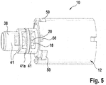
- FIG. 5 shows a further perspective view of the slide valve 10.
- the radially outer shell portion 16 in contrast to the FIG. 4 was in the drawing of FIG. 5 omitted the radially outer shell portion 16 so that the radially middle portion 38 and the slide sleeve 18 and the valve spool 20 can be seen better.
Description
Die Erfindung betrifft ein Schieberventil nach dem Oberbegriff des Anspruchs 1.The invention relates to a slide valve according to the preamble of claim 1.
Vom Markt her bekannt sind Automatikgetriebe für Kraftfahrzeuge, bei welchen zum Wechseln der Gänge hydraulisch betätigbare Kupplungen verwendet werden. Damit Schaltvorgänge ruckfrei und für den Fahrer unmerklich ablaufen, ist eine vergleichsweise hohe Präzision der hydraulischen Komponenten erforderlich. Beispielsweise werden dafür elektromagnetisch betätigbare Druckregelventile verwendet. Patentveröffentlichungen aus diesem Fachgebiet sind beispielsweise die
Das der Erfindung zugrunde liegende Problem wird durch ein Schieberventil nach Anspruch 1 gelöst. Vorteilhafte Weiterbildungen sind in Unteransprüchen angegeben. Für die Erfindung wichtige Merkmale finden sich ferner in der nachfolgenden Beschreibung und in den Zeichnungen, wobei die Merkmale sowohl in Alleinstellung als auch in unterschiedlichen Kombinationen für die Erfindung wichtig sein können, ohne dass hierauf nochmals explizit hingewiesen wird.The problem underlying the invention is achieved by a slide valve according to claim 1. Advantageous developments are specified in subclaims. Features which are important for the invention can also be found in the following description and in the drawings, wherein the features, both alone and in different combinations, can be important for the invention, without being explicitly referred to again.
Die Erfindung betrifft ein Schieberventil, welches insbesondere als Druckregelventil für ein Automatikgetriebe eines Kraftfahrzeugs verwendet werden kann, mit einem Gehäuse und mit einem in einer Führungsausnehmung des Gehäuses angeordneten axial bewegbaren Ventilschieber. Dabei umfasst das Gehäuse mindestens einen radialen Zulaufanschluss und einen von diesem axial beabstandeten radialen Ablaufanschluss und einen stirnseitigen Arbeitsanschluss, wobei an der Führungsausnehmung mindestens eine mit dem Zulaufanschluss verbundene erste Steueröffnung und eine von dieser axial beabstandete und mit dem Ablaufanschluss verbundene zweite Steueröffnung und eine axial zwischen diesen beiden angeordnete und mit dem Arbeitsanschluss verbundene dritte Steueröffnung vorhanden ist, wobei die ersten und zweiten Steueröffnungen mit einem ersten und einem zweiten Steuerabschnitt an dem Ventilschieber hydraulisch kooperieren können, und wobei in dem Gehäuse ein bereichsweise axial verlaufender Verbindungskanal vorhanden ist, der die dritte Steueröffnung mit dem Arbeitsanschluss verbindet. Erfindungsgemäß weist das Gehäuse einen aus Kunststoff hergestellten Abschnitt auf, in dem der Verbindungskanal ausgebildet ist.The invention relates to a slide valve, which can be used in particular as a pressure control valve for an automatic transmission of a motor vehicle, with a housing and with a arranged in a guide recess of the housing axially movable valve spool. Includes the housing having at least one radial inlet connection and a radial outlet connection and an end-side working connection axially spaced from the guide recess, at least one first control opening connected to the inlet connection and a second control opening axially spaced therefrom and connected to the discharge connection and one axially between the two arranged and connected to the working port third control port is provided, wherein the first and second control ports can cooperate hydraulically with a first and a second control section on the valve spool, and wherein in the housing a partially axially extending connecting channel is present, the third control port with the Work connection connects. According to the invention, the housing has a section made of plastic, in which the connecting channel is formed.
Dadurch kann das Schieberventil besonders kostengünstig hergestellt werden, wobei ein vergleichsweise großer hydraulischer Querschnitt in der Verbindung zu dem stirnseitigen Arbeitsanschluss ermöglicht wird. Insbesondere sind eine externe hydraulische Verbindung zu dem Arbeitsanschluss und ein dazu erforderlicher zusätzlicher Hydraulikanschluss an dem Gehäuse des Schieberventils entbehrlich. Ebenso ist es nicht erforderlich, dass der Ventilschieber einen axialen und/oder radialen Kanal aufweist, welcher beispielsweise mittels einer zentrischen bzw. radialen Bohrung auszuführen wäre. Das erfindungsgemäße Schieberventil ermöglicht also vergleichsweise große hydraulische Durchflüsse und somit ein gutes dynamisches Verhalten.As a result, the slide valve can be produced in a particularly cost-effective manner, with a comparatively large hydraulic cross-section being made possible in the connection to the end-side working connection. In particular, an external hydraulic connection to the working port and a required additional hydraulic connection to the housing of the slide valve are dispensable. Likewise, it is not necessary that the valve slide has an axial and / or radial channel, which would be carried out for example by means of a centric or radial bore. The slide valve according to the invention thus allows comparatively large hydraulic flows and thus a good dynamic behavior.
Gemäß der Erfindung umfasst das Gehäuse eine vorzugsweise aus Metall hergestellte Schieberhülse, in der die Führungsausnehmung und die Steueröffnungen ausgebildet sind und die mit Kunststoff umspritzt ist, wodurch der aus Kunststoff hergestellte Abschnitt gebildet wird. Dadurch kann das Schieberventil besonders einfach und dennoch robust hergestellt und ein Gewicht des Schieberventils reduziert werden. Ein zur Herstellung der Schieberhülse erforderliches Zerspanungsvolumen ist vergleichsweise klein, wodurch Kosten gesenkt werden. Inneneinstiche und/oder gefräste Kanäle an einem Außendurchmesser der Schieberhülse sind entbehrlich. Kunststoffspritzteile sind ferner in der Herstellung besonders preiswert.According to the invention, the housing comprises a sliding sleeve made preferably of metal, in which the guide recess and the control openings are formed and which is encapsulated in plastic, whereby the section made of plastic is formed. As a result, the slide valve can be made particularly simple yet robust and a weight of the slide valve can be reduced. A required for the production of the sliding sleeve machining volume is relatively small, thereby reducing costs. Internal grooves and / or milled channels on an outer diameter of the sliding sleeve are dispensable. Plastic injection parts are also particularly inexpensive to manufacture.
Weiterhin kann vorgesehen sein, dass das Gehäuse ein radial äußeres Mantelteil umfasst, welches auf den aus Kunststoff hergestellten Abschnitt aufgepresst ist und an dem der Zulaufanschluss, der Ablaufanschluss und der Arbeitsanschluss ausgebildet sind. Mittels des Aufpressens kann eine Montage des Schieberventils besonders einfach durchgeführt werden. Insbesondere erfolgen die jeweiligen Pressverbindungen an radial geschlossenen Ringflächen zwischen dem Gehäuse und dem äußeren Mantelteil, wodurch eine große hydraulische Dichtheit ermöglicht wird. Das Mantelteil ist ferner einfach und ohne spezielle Winkelorientierung montierbar.Furthermore, it can be provided that the housing comprises a radially outer jacket part which is pressed onto the section made of plastic and to which the inlet connection, the outlet connection and the working connection are formed. By means of pressing a mounting of the slide valve can be carried out very easily. In particular, the respective press connections are made on radially closed annular surfaces between the housing and the outer shell part, whereby a large hydraulic tightness is made possible. The jacket part is also easy to install without special angular orientation.
Ergänzend kann vorgesehen sein, dass das Mantelteil mindestens ein einem Anschluss zugeordnetes Filtersieb umfasst. Beispielsweise ist das Filtersieb stirnseitig an dem Mantelteil ausgebildet und somit dem Arbeitsanschluss zugeordnet. Dadurch ist ein externes hydraulisches Filter gegebenenfalls entbehrlich, wodurch Kosten gespart werden können. Das Mantelteil kann ebenfalls ein Spritzgussteil sein, in welches die Filter beim Spritzguss eingearbeitet werden.In addition, it can be provided that the casing part comprises at least one filter screen associated with a connection. For example, the filter screen is formed on the front side of the shell part and thus associated with the working port. As a result, an external hydraulic filter may be unnecessary, which costs can be saved. The jacket part may also be an injection molded part, in which the filters are incorporated during injection molding.
In einer weiteren Ausgestaltung des Schieberventils weist der Ventilschieber in einem jeweiligen Bereich des ersten und zweiten schieberseitigen Steuerabschnitts einen im Wesentlichen gleichen Durchmesser auf und ist somit im Wesentlichen ohne Durchmesserstufen ausgeführt. Dadurch kann die Herstellung des Ventilschiebers und ebenso der Schieberhülse vereinfacht und verbilligt werden.In a further embodiment of the slide valve, the valve slide in a respective region of the first and second slide-side control section has a substantially same diameter and is thus designed substantially without diameter steps. As a result, the production of the valve spool and also the sliding sleeve can be simplified and cheapened.
Weiterhin kann vorgesehen sein, dass der Verbindungskanal mindestens zwei axial verlaufende Teil-Kanäle umfasst, welche in einem radialen Winkel von 90 Grad in Bezug auf mindestens einen der radialen Anschlüsse des Schieberventils angeordnet sind. Die Teil-Kanäle sind mittels Ausnehmungen und/oder Hohlräumen an dem aus Kunststoff hergestellten Abschnitt ausgebildet. Dadurch wird ein vergleichsweise großer hydraulischer Querschnitt des Verbindungskanals ermöglicht, und der Betrieb des Schieberventils somit verbessert. Beispielsweise weisen die axialen Teil-Kanäle zumindest abschnittsweise einen in etwa kreissegmentförmigen oder sichelförmigen Querschnitt auf. Dadurch ergibt sich eine für das erfindungsgemäße Schieberventil besonders geeignete Querschnittsform für den bereichsweise axial verlaufenden Verbindungskanal.Furthermore, it can be provided that the connecting channel comprises at least two axially extending part-channels, which are arranged at a radial angle of 90 degrees with respect to at least one of the radial connections of the slide valve. The sub-channels are formed by means of recesses and / or cavities on the section made of plastic. As a result, a comparatively large hydraulic cross section of the connecting channel is made possible, and the operation of the slide valve is thus improved. For example, the axial part-channels at least in sections on an approximately circular segment-shaped or crescent-shaped cross-section. This results in a for the inventive Slider valve particularly suitable cross-sectional shape for the partially axially extending connecting channel.
Der Betrieb des Schieberventils kann besonders einfach und präzise erfolgen, wenn es elektromagnetisch betätigbar ist, wobei der Ventilschieber einerseits von einer axial wirkenden Druckfeder und andererseits durch elektromagnetische Kraft axial beaufschlagbar ist. Ein jeweiliges Kräftegleichgewicht zwischen der Federkraft und der elektromagnetischen Kraft - unter Berücksichtigung eventueller hydraulischer Kräfte - bestimmt somit eine axiale Position des Ventilschiebers in der Schieberhülse.The operation of the slide valve can be particularly simple and precise, if it is electromagnetically actuated, wherein the valve spool is axially acted upon on the one hand by an axially acting compression spring and on the other hand by electromagnetic force. A respective balance of forces between the spring force and the electromagnetic force - taking into account any hydraulic forces - thus determines an axial position of the valve spool in the sliding sleeve.
Nachfolgend werden beispielhafte Ausführungsformen der Erfindung unter Bezugnahme auf die Zeichnung erläutert. In der Zeichnung zeigen:
- Figur 1
- eine erste axiale Schnittansicht eines Schieberventils für ein Automatikgetriebe eines Kraftfahrzeugs;
- Figur 2
- eine zweite axiale Schnittansicht des Schieberventils von
Figur 1 ; - Figur 3
- eine perspektivische Darstellung eines radialen Schnitts durch das Schieberventil entlang einer Linie III-III von
Figur 2 ; - Figur 4
- eine erste perspektivische Darstellung des Schieberventils; und
- Figur 5
- eine zweite perspektivische Darstellung des Schieberventils.
- FIG. 1
- a first axial sectional view of a slide valve for an automatic transmission of a motor vehicle;
- FIG. 2
- a second axial sectional view of the slide valve of
FIG. 1 ; - FIG. 3
- a perspective view of a radial section through the gate valve along a line III-III of
FIG. 2 ; - FIG. 4
- a first perspective view of the slide valve; and
- FIG. 5
- a second perspective view of the slide valve.
Es werden für funktionsäquivalente Elemente und Größen in allen Figuren auch bei unterschiedlichen Ausführungsformen die gleichen Bezugszeichen verwendet.The same reference numerals are used for functionally equivalent elements and sizes in all figures, even in different embodiments.
Das Schieberventil 10 umfasst ein Gehäuse 14 mit einem in etwa hutförmig ausgebildeten radial äußeren Mantelteil 16, bei dem es sich um ein Kunststoff-Spritzgussteil handelt. An dem äußeren Mantelteil 16 ist stirnseitig (also in der
Weiterhin umfasst das Gehäuse 14 einen radialen Zulaufanschluss 22 und einen von diesem axial beabstandeten radialen Ablaufanschluss 24, sowie einen stirnseitigen Arbeitsanschluss 26, welcher in der
An der Schieberhülse 18 bzw. an der Führungsausnehmung 19 sind in Umfangsrichtung gleichmäßig verteilt vier mit dem Zulaufanschluss 22 verbundene erste Steueröffnungen 28, und vier von diesen axial beabstandete und mit dem Ablaufanschluss 24 verbundene zweite Steueröffnungen 30, und vier axial zwischen den ersten und zweiten Steueröffnungen 28 und 30 angeordnete und mit dem Arbeitsanschluss 26 verbundene dritte Steueröffnungen 32 vorhanden. Wegen der vorliegenden Schnittansicht sind in der
Die ersten und zweiten Steueröffnungen 28 und 30 können jeweils mit einem ersten und einem zweiten jeweils eine umlaufende Steuerkante umfassenden schieberseitigen Steuerabschnitt 34 und 36 an dem Ventilschieber 20 hydraulisch kooperieren. Insbesondere weist der Ventilschieber 20 in einem jeweiligen Bereich des ersten und zweiten schieberseitigen Steuerabschnitts 34 und 36 einen im Wesentlichen gleichen Durchmesser auf. Zwischen den Steuerabschnitten 34 und 36 weist der Ventilschieber 20 eine sich axial erstreckende radial umlaufende Ausnehmung 37 auf. Weiterhin umfasst das Gehäuse 14 einen radial zwischen der Schieberhülse 18 und dem äußeren Mantelteil 16 angeordneten radial mittleren Abschnitt 38. Das äußere Mantelteil 16, der radial mittlere Abschnitt 38, die vorzugsweise aus Metall hergestellte Schieberhülse 18 sowie der Ventilschieber 20 sind jeweils zumindest teilweise rotationsymmetrisch ausgeführt.The first and
In dem radial mittleren Abschnitt 38 ist ein Verbindungskanal 40 ausgebildet, welcher bereichsweise axial verläuft und die dritten Steueröffnungen 32 mit dem Arbeitsanschluss 26 hydraulisch verbindet. Der Verbindungskanal 40 umfasst einen ersten und einen zweiten axialen Teil-Kanal 40a und 40b, welche radial um 180 Grad zueinander versetzt angeordnet sind, wie weiter unten bei den
Vorliegend ist der radial mittlere Abschnitt 38 aus einem Kunststoff hergestellt, indem die (meist metallische) Schieberhülse 18 von dem Kunststoff umspritzt ist. Dazu weist die Schieberhülse 18 eine Mehrzahl von axial verteilt angeordneten radial umlaufenden äußeren Nuten bzw. Rippen (ohne Bezugszeichen) auf, so dass beide Elemente sozusagen ineinander verzahnt sind und eine Einheit bilden. Der radial mittlere Abschnitt 38 ist vorliegend an drei axial beabstandeten radial äußeren Abschnitten 41 gegen entsprechende radial innere Abschnitte des äußeren Mantelteils 16 verpresst, wodurch beide Elemente kraftschlüssig miteinander verbunden sind. Die radial äußeren Abschnitte 41 können - wie vorliegend - zumindest einen radial umlaufenden Steg 41a aufweisen, wodurch die Verpressung gegen das radial äußere Mantelteil 16 verbessert und somit auch die Dichtheit erhöht wird.In the present case, the radially
An einem zapfenförmig ausgebildeten in der Zeichnung linken Endabschnitt (ohne Bezugszeichen) des Ventilschiebers 20 greift eine als Schraubenfeder ausgeführte Druckfeder 42 an. Ein axial entgegengesetzter Abschnitt der Druckfeder 42 ist an einem ebenfalls zapfenförmig ausgebildeten zentrischen Abschnitt 44 des äußeren Mantelteils 16 gehalten. Somit kann die Druckfeder 42 den Ventilschieber 20 in der Zeichnung nach rechts mit einer Druckkraft beaufschlagen. Diese Druckkraft wirkt gemeinsam mit der Hydraulikkraft, die durch Beaufschlagung der in der Zeichnung linken Stirnfläche mit dem dort anliegenden Druck im Arbeitsanschluss 26 entsteht. Eine in der Zeichnung rechte Stirnfläche des Ventilschiebers 20 wird von einem Betätigungsstift 46 des elektromagnetischen Aktors 12 beaufschlagt.At a peg-shaped in the drawing left end portion (without reference numeral) of the
Weiterhin umfasst das Schieberventil 10 zwei in radial umlaufenden äußeren Nuten des äußeren Mantelteils 16 angeordnete ringförmige O-Ring-Dichtungen 48, welche im eingebauten Zustand des Schieberventils 10 den Ablaufanschluss 24 gegen den Zulaufanschluss 22 und den Zulaufanschluss 22 gegen den Arbeitsanschluss 26 hydraulisch dichten können.Furthermore, the
Bei der Herstellung des Schieberventils 10 können die radialen Steueröffnungen 28, 30 und 32 der Schieberhülse 18 in einem Spritzwerkzeug mittels Werkzeugbacken freigehalten werden. Zwischen den Steueröffnungen 28 und 32 bzw. 32 und 30 bildet der Kunststoff ringförmige Bereiche, welche als Dichtstellen zur Abdichtung des Zulaufanschlusses 22 gegen den Arbeitsanschluss 26 bzw. des Arbeitsanschlusses 26 gegen den Ablaufanschluss 24 verwendet werden. Weitere Dichtstellen ergeben sich - wie oben bereits beschrieben - mittels der Pressverbindungen zwischen dem radial mittleren Abschnitt 38 und dem radial äußeren Mantelteil 16.During the production of the
In der
Im Betrieb des Schieberventils 10 der
In einer zweiten Position des Ventilschiebers 20 (wie in der
Claims (7)
- Slide valve (10), in particular for an automatic transmission of a motor vehicle, having a housing (14) and having an axially movable valve slide (20) arranged in a guide recess (19) of the housing (14), wherein the housing (14) comprises at least one radial feed port (22) and one radial discharge port (24) spaced apart axially therefrom and one face-side working port (26), wherein, at the guide recess (19), there are provided at least one first control opening (28), which is connected to the feed port (22), and one second control opening (30), which is axially spaced apart from said at least one first control opening and which is connected to the discharge port (24), and one third control opening (32), which is arranged axially between said at least one first control opening and said at least one second control opening and which is connected to the working port (26), wherein the first and second control openings (28, 30) can hydraulically cooperate with a first and a second control section (34, 36) on the valve slide (20), and wherein, in the housing (14), there is provided a connecting duct (40) which runs axially in regions and which connects the third control opening (32) to the working port (26), characterized in that the housing (14) comprises a slide sleeve (18) which is preferably produced from metal and in which the guide recess (19) and the control openings (28, 30, 32) are formed and which is encapsulated with plastic, whereby a section (38) produced from plastic is formed, in which the connecting duct (40) is formed.
- Slide valve (10) according to Claim 1, characterized in that the housing (14) comprises a radially outer shell part (16), which is pressed onto the section (38) produced from plastic and on which the feed port (22), the discharge port (24) and the working port (26) are formed.
- Slide valve (10) according to Claim 2, characterized in that the shell part (16) comprises at least one filter screen (17) assigned to a port (22, 24, 26).
- Slide valve (10) according to at least one of the preceding claims, characterized in that the valve slide (20) has a substantially equal diameter in a respective region of the first and of the second control section (34, 36) on the slide.
- Slide valve (10) according to at least one of the preceding claims, characterized in that the connecting duct (40) comprises at least two axially running duct parts (40a, 40b) which are arranged at a radial angle of 90 degrees in relation to at least one of the radial ports (22, 24) of the slide valve (10).
- Slide valve (10) according to Claim 5, characterized in that the axial duct parts (40a, 40b) have a circular-segment-shaped or sickle-shaped cross section at least in sections.
- Slide valve (10) according to at least one of the preceding claims, characterized in that it is electromagnetically actuable, wherein the valve slide (20) is acted on axially at one side by an axially acting pressure spring (42) and at the other side by an electromagnetic force.
Applications Claiming Priority (2)
| Application Number | Priority Date | Filing Date | Title |
|---|---|---|---|
| DE201310221218 DE102013221218A1 (en) | 2013-10-18 | 2013-10-18 | Slide valve, in particular for an automatic transmission of a motor vehicle |
| PCT/EP2014/068038 WO2015055340A1 (en) | 2013-10-18 | 2014-08-26 | Spool valve, in particular for an automatic transmission of a motor vehicle |
Publications (2)
| Publication Number | Publication Date |
|---|---|
| EP3058257A1 EP3058257A1 (en) | 2016-08-24 |
| EP3058257B1 true EP3058257B1 (en) | 2018-02-21 |
Family
ID=51398630
Family Applications (1)
| Application Number | Title | Priority Date | Filing Date |
|---|---|---|---|
| EP14755387.9A Active EP3058257B1 (en) | 2013-10-18 | 2014-08-26 | Spool valve, in particular for an automatic transmission of a motor vehicle |
Country Status (6)
| Country | Link |
|---|---|
| US (1) | US10520105B2 (en) |
| EP (1) | EP3058257B1 (en) |
| KR (1) | KR102172740B1 (en) |
| CN (1) | CN105612375B (en) |
| DE (1) | DE102013221218A1 (en) |
| WO (1) | WO2015055340A1 (en) |
Families Citing this family (9)
| Publication number | Priority date | Publication date | Assignee | Title |
|---|---|---|---|---|
| DE102013221218A1 (en) * | 2013-10-18 | 2015-04-23 | Robert Bosch Gmbh | Slide valve, in particular for an automatic transmission of a motor vehicle |
| DE102015110733A1 (en) * | 2014-07-11 | 2016-01-14 | Hilite Germany Gmbh | Valve, in particular hydraulic valve |
| US10907740B2 (en) * | 2015-12-15 | 2021-02-02 | Husco Automotive Holdings Llc | Control valve having a metal sleeve within a plastic valve body |
| IT201600122165A1 (en) * | 2016-12-01 | 2018-06-01 | Piaggio & C Spa | Synchronized transmission, in particular for motor vehicles |
| CN106763970A (en) * | 2016-12-16 | 2017-05-31 | 中国矿业大学(北京) | A kind of hydraulic valve body of composite |
| ES2926960T3 (en) * | 2016-12-23 | 2022-10-31 | Svm Schultz Verwaltungs Gmbh & Co Kg | Slide valve with channel |
| RU2697298C2 (en) * | 2018-02-07 | 2019-08-13 | СВМ Шульц Фервальтунгс-ГмбХ энд Ко. КГ | Slide valve with channel |
| US10598298B2 (en) | 2018-08-27 | 2020-03-24 | Borg Warner Inc. | Control valve and hydraulic control module including the same |
| JP7202446B2 (en) * | 2019-03-27 | 2023-01-11 | ジヤトコ株式会社 | automatic transmission |
Citations (1)
| Publication number | Priority date | Publication date | Assignee | Title |
|---|---|---|---|---|
| DE3224119A1 (en) * | 1982-06-29 | 1983-12-29 | Robert Bosch Gmbh, 7000 Stuttgart | HYDRAULIC ELECTROMAGNETICALLY ACTUATED VALVE |
Family Cites Families (9)
| Publication number | Priority date | Publication date | Assignee | Title |
|---|---|---|---|---|
| US6142272A (en) * | 1997-08-26 | 2000-11-07 | Luk Getriebe-Systeme Gmbh | Hydrodynamic torque converter |
| DE19847021B4 (en) | 1998-10-13 | 2007-01-04 | Robert Bosch Gmbh | Pressure control valve |
| DE20100950U1 (en) | 2001-01-19 | 2002-05-23 | Bosch Gmbh Robert | Electromagnetic actuator |
| JP4172211B2 (en) * | 2002-06-06 | 2008-10-29 | 株式会社デンソー | Flow control device |
| CN101911166B (en) * | 2008-01-15 | 2013-08-21 | 株式会社半导体能源研究所 | Light-emitting device |
| DE102009031701A1 (en) * | 2009-07-04 | 2011-01-05 | Schaeffler Technologies Gmbh & Co. Kg | Central valve of a camshaft adjuster of an internal combustion engine |
| DE102010039918A1 (en) * | 2010-08-30 | 2012-03-01 | Robert Bosch Gmbh | Pressure control valve in slide construction with improved damping behavior |
| DE102011006855A1 (en) * | 2011-04-06 | 2012-10-11 | Robert Bosch Gmbh | Slide valve used as pressure regulating valve for automatic transmission of motor car, has slider including control edges which are engaged with control openings which are extended in circumferential direction of guide surface |
| DE102013221218A1 (en) | 2013-10-18 | 2015-04-23 | Robert Bosch Gmbh | Slide valve, in particular for an automatic transmission of a motor vehicle |
-
2013
- 2013-10-18 DE DE201310221218 patent/DE102013221218A1/en not_active Withdrawn
-
2014
- 2014-08-26 CN CN201480056956.1A patent/CN105612375B/en active Active
- 2014-08-26 KR KR1020167009891A patent/KR102172740B1/en active IP Right Grant
- 2014-08-26 EP EP14755387.9A patent/EP3058257B1/en active Active
- 2014-08-26 WO PCT/EP2014/068038 patent/WO2015055340A1/en active Application Filing
- 2014-08-26 US US15/029,229 patent/US10520105B2/en active Active
Patent Citations (1)
| Publication number | Priority date | Publication date | Assignee | Title |
|---|---|---|---|---|
| DE3224119A1 (en) * | 1982-06-29 | 1983-12-29 | Robert Bosch Gmbh, 7000 Stuttgart | HYDRAULIC ELECTROMAGNETICALLY ACTUATED VALVE |
Also Published As
| Publication number | Publication date |
|---|---|
| KR102172740B1 (en) | 2020-11-02 |
| US10520105B2 (en) | 2019-12-31 |
| CN105612375A (en) | 2016-05-25 |
| KR20160072117A (en) | 2016-06-22 |
| WO2015055340A1 (en) | 2015-04-23 |
| CN105612375B (en) | 2018-08-14 |
| US20160305566A1 (en) | 2016-10-20 |
| EP3058257A1 (en) | 2016-08-24 |
| DE102013221218A1 (en) | 2015-04-23 |
Similar Documents
| Publication | Publication Date | Title |
|---|---|---|
| EP3058257B1 (en) | Spool valve, in particular for an automatic transmission of a motor vehicle | |
| EP1752691B1 (en) | Control spool valve and its manufacturing process | |
| EP1810764A1 (en) | Method for producing valve casings and valve casing | |
| EP2359040B1 (en) | Valve and assembly method | |
| DE102012106096B3 (en) | Swivel motor adjuster with a hydraulic valve | |
| WO2009062783A1 (en) | Pump assembly for synchronous pressurization of two fluid circuits | |
| EP3047183B1 (en) | Control device for selectively fluidically connecting and disconnecting fluid connection points | |
| WO2011045171A2 (en) | Double internal gear pump | |
| DE102015203378A1 (en) | Internal combustion engine with adjustable variable compression ratio and a switching module | |
| EP2245277B1 (en) | Hydraulic medium insert for a control valve in a hydraulic actuator | |
| DE102011006855A1 (en) | Slide valve used as pressure regulating valve for automatic transmission of motor car, has slider including control edges which are engaged with control openings which are extended in circumferential direction of guide surface | |
| WO2010040511A1 (en) | Pressure limiting and suction valve unit | |
| DE102014214610B4 (en) | Camshaft adjusting device for an internal combustion engine | |
| DE102013223103A1 (en) | Valve, in particular solenoid valve | |
| DE102014017801A1 (en) | Pressure relief valve | |
| DE3309998A1 (en) | Hydraulic device for the selection and transmission of a pressure signal in a block-type directional control valve | |
| EP0129726B1 (en) | Hydraulic control valve with a housing | |
| DE102005011138B4 (en) | Pilot operated pressure shut-off valve | |
| DE102009060297A1 (en) | Solenoid valve and driver assistance device | |
| EP0775826A1 (en) | Screw compressor | |
| DE19802289A1 (en) | Directional control valve | |
| DE102006048184A1 (en) | Master cylinder for hydraulic installation of vehicle, has pipe-shaped sleeve with axis, which is inserted between piston and wall of main bore | |
| EP0433665B1 (en) | Hydraulic control valve | |
| DE19945183A1 (en) | Seat valve | |
| DE102012214247A1 (en) | Slide valve for controlling hydraulic pressures or hydraulic flow rates, such as in automatic transmissions of motor vehicles, has valve slider having slide-sided control edge, where housing-sided control edge is formed on borehole |
Legal Events
| Date | Code | Title | Description |
|---|---|---|---|
| PUAI | Public reference made under article 153(3) epc to a published international application that has entered the european phase |
Free format text: ORIGINAL CODE: 0009012 |
|
| 17P | Request for examination filed |
Effective date: 20160518 |
|
| AK | Designated contracting states |
Kind code of ref document: A1 Designated state(s): AL AT BE BG CH CY CZ DE DK EE ES FI FR GB GR HR HU IE IS IT LI LT LU LV MC MK MT NL NO PL PT RO RS SE SI SK SM TR |
|
| AX | Request for extension of the european patent |
Extension state: BA ME |
|
| DAX | Request for extension of the european patent (deleted) | ||
| TPAC | Observations filed by third parties |
Free format text: ORIGINAL CODE: EPIDOSNTIPA |
|
| 17Q | First examination report despatched |
Effective date: 20170524 |
|
| GRAP | Despatch of communication of intention to grant a patent |
Free format text: ORIGINAL CODE: EPIDOSNIGR1 |
|
| INTG | Intention to grant announced |
Effective date: 20171109 |
|
| GRAS | Grant fee paid |
Free format text: ORIGINAL CODE: EPIDOSNIGR3 |
|
| GRAA | (expected) grant |
Free format text: ORIGINAL CODE: 0009210 |
|
| AK | Designated contracting states |
Kind code of ref document: B1 Designated state(s): AL AT BE BG CH CY CZ DE DK EE ES FI FR GB GR HR HU IE IS IT LI LT LU LV MC MK MT NL NO PL PT RO RS SE SI SK SM TR |
|
| REG | Reference to a national code |
Ref country code: GB Ref legal event code: FG4D Free format text: NOT ENGLISH |
|
| REG | Reference to a national code |
Ref country code: CH Ref legal event code: EP |
|
| REG | Reference to a national code |
Ref country code: AT Ref legal event code: REF Ref document number: 972123 Country of ref document: AT Kind code of ref document: T Effective date: 20180315 |
|
| REG | Reference to a national code |
Ref country code: IE Ref legal event code: FG4D Free format text: LANGUAGE OF EP DOCUMENT: GERMAN |
|
| REG | Reference to a national code |
Ref country code: DE Ref legal event code: R096 Ref document number: 502014007345 Country of ref document: DE |
|
| REG | Reference to a national code |
Ref country code: NL Ref legal event code: MP Effective date: 20180221 |
|
| REG | Reference to a national code |
Ref country code: LT Ref legal event code: MG4D |
|
| PG25 | Lapsed in a contracting state [announced via postgrant information from national office to epo] |
Ref country code: HR Free format text: LAPSE BECAUSE OF FAILURE TO SUBMIT A TRANSLATION OF THE DESCRIPTION OR TO PAY THE FEE WITHIN THE PRESCRIBED TIME-LIMIT Effective date: 20180221 Ref country code: NL Free format text: LAPSE BECAUSE OF FAILURE TO SUBMIT A TRANSLATION OF THE DESCRIPTION OR TO PAY THE FEE WITHIN THE PRESCRIBED TIME-LIMIT Effective date: 20180221 Ref country code: CY Free format text: LAPSE BECAUSE OF FAILURE TO SUBMIT A TRANSLATION OF THE DESCRIPTION OR TO PAY THE FEE WITHIN THE PRESCRIBED TIME-LIMIT Effective date: 20180221 Ref country code: ES Free format text: LAPSE BECAUSE OF FAILURE TO SUBMIT A TRANSLATION OF THE DESCRIPTION OR TO PAY THE FEE WITHIN THE PRESCRIBED TIME-LIMIT Effective date: 20180221 Ref country code: LT Free format text: LAPSE BECAUSE OF FAILURE TO SUBMIT A TRANSLATION OF THE DESCRIPTION OR TO PAY THE FEE WITHIN THE PRESCRIBED TIME-LIMIT Effective date: 20180221 Ref country code: FI Free format text: LAPSE BECAUSE OF FAILURE TO SUBMIT A TRANSLATION OF THE DESCRIPTION OR TO PAY THE FEE WITHIN THE PRESCRIBED TIME-LIMIT Effective date: 20180221 Ref country code: NO Free format text: LAPSE BECAUSE OF FAILURE TO SUBMIT A TRANSLATION OF THE DESCRIPTION OR TO PAY THE FEE WITHIN THE PRESCRIBED TIME-LIMIT Effective date: 20180521 |
|
| PG25 | Lapsed in a contracting state [announced via postgrant information from national office to epo] |
Ref country code: LV Free format text: LAPSE BECAUSE OF FAILURE TO SUBMIT A TRANSLATION OF THE DESCRIPTION OR TO PAY THE FEE WITHIN THE PRESCRIBED TIME-LIMIT Effective date: 20180221 Ref country code: SE Free format text: LAPSE BECAUSE OF FAILURE TO SUBMIT A TRANSLATION OF THE DESCRIPTION OR TO PAY THE FEE WITHIN THE PRESCRIBED TIME-LIMIT Effective date: 20180221 Ref country code: GR Free format text: LAPSE BECAUSE OF FAILURE TO SUBMIT A TRANSLATION OF THE DESCRIPTION OR TO PAY THE FEE WITHIN THE PRESCRIBED TIME-LIMIT Effective date: 20180522 Ref country code: BG Free format text: LAPSE BECAUSE OF FAILURE TO SUBMIT A TRANSLATION OF THE DESCRIPTION OR TO PAY THE FEE WITHIN THE PRESCRIBED TIME-LIMIT Effective date: 20180521 Ref country code: RS Free format text: LAPSE BECAUSE OF FAILURE TO SUBMIT A TRANSLATION OF THE DESCRIPTION OR TO PAY THE FEE WITHIN THE PRESCRIBED TIME-LIMIT Effective date: 20180221 |
|
| PG25 | Lapsed in a contracting state [announced via postgrant information from national office to epo] |
Ref country code: MT Free format text: LAPSE BECAUSE OF FAILURE TO SUBMIT A TRANSLATION OF THE DESCRIPTION OR TO PAY THE FEE WITHIN THE PRESCRIBED TIME-LIMIT Effective date: 20180221 |
|
| PG25 | Lapsed in a contracting state [announced via postgrant information from national office to epo] |
Ref country code: AL Free format text: LAPSE BECAUSE OF FAILURE TO SUBMIT A TRANSLATION OF THE DESCRIPTION OR TO PAY THE FEE WITHIN THE PRESCRIBED TIME-LIMIT Effective date: 20180221 Ref country code: PL Free format text: LAPSE BECAUSE OF FAILURE TO SUBMIT A TRANSLATION OF THE DESCRIPTION OR TO PAY THE FEE WITHIN THE PRESCRIBED TIME-LIMIT Effective date: 20180221 Ref country code: RO Free format text: LAPSE BECAUSE OF FAILURE TO SUBMIT A TRANSLATION OF THE DESCRIPTION OR TO PAY THE FEE WITHIN THE PRESCRIBED TIME-LIMIT Effective date: 20180221 Ref country code: IT Free format text: LAPSE BECAUSE OF FAILURE TO SUBMIT A TRANSLATION OF THE DESCRIPTION OR TO PAY THE FEE WITHIN THE PRESCRIBED TIME-LIMIT Effective date: 20180221 Ref country code: EE Free format text: LAPSE BECAUSE OF FAILURE TO SUBMIT A TRANSLATION OF THE DESCRIPTION OR TO PAY THE FEE WITHIN THE PRESCRIBED TIME-LIMIT Effective date: 20180221 |
|
| REG | Reference to a national code |
Ref country code: DE Ref legal event code: R097 Ref document number: 502014007345 Country of ref document: DE |
|
| PG25 | Lapsed in a contracting state [announced via postgrant information from national office to epo] |
Ref country code: SM Free format text: LAPSE BECAUSE OF FAILURE TO SUBMIT A TRANSLATION OF THE DESCRIPTION OR TO PAY THE FEE WITHIN THE PRESCRIBED TIME-LIMIT Effective date: 20180221 Ref country code: CZ Free format text: LAPSE BECAUSE OF FAILURE TO SUBMIT A TRANSLATION OF THE DESCRIPTION OR TO PAY THE FEE WITHIN THE PRESCRIBED TIME-LIMIT Effective date: 20180221 Ref country code: DK Free format text: LAPSE BECAUSE OF FAILURE TO SUBMIT A TRANSLATION OF THE DESCRIPTION OR TO PAY THE FEE WITHIN THE PRESCRIBED TIME-LIMIT Effective date: 20180221 Ref country code: SK Free format text: LAPSE BECAUSE OF FAILURE TO SUBMIT A TRANSLATION OF THE DESCRIPTION OR TO PAY THE FEE WITHIN THE PRESCRIBED TIME-LIMIT Effective date: 20180221 |
|
| PLBE | No opposition filed within time limit |
Free format text: ORIGINAL CODE: 0009261 |
|
| STAA | Information on the status of an ep patent application or granted ep patent |
Free format text: STATUS: NO OPPOSITION FILED WITHIN TIME LIMIT |
|
| 26N | No opposition filed |
Effective date: 20181122 |
|
| PG25 | Lapsed in a contracting state [announced via postgrant information from national office to epo] |
Ref country code: SI Free format text: LAPSE BECAUSE OF FAILURE TO SUBMIT A TRANSLATION OF THE DESCRIPTION OR TO PAY THE FEE WITHIN THE PRESCRIBED TIME-LIMIT Effective date: 20180221 |
|
| PG25 | Lapsed in a contracting state [announced via postgrant information from national office to epo] |
Ref country code: MC Free format text: LAPSE BECAUSE OF FAILURE TO SUBMIT A TRANSLATION OF THE DESCRIPTION OR TO PAY THE FEE WITHIN THE PRESCRIBED TIME-LIMIT Effective date: 20180221 |
|
| REG | Reference to a national code |
Ref country code: CH Ref legal event code: PL |
|
| GBPC | Gb: european patent ceased through non-payment of renewal fee |
Effective date: 20180826 |
|
| PG25 | Lapsed in a contracting state [announced via postgrant information from national office to epo] |
Ref country code: CH Free format text: LAPSE BECAUSE OF NON-PAYMENT OF DUE FEES Effective date: 20180831 Ref country code: LI Free format text: LAPSE BECAUSE OF NON-PAYMENT OF DUE FEES Effective date: 20180831 Ref country code: LU Free format text: LAPSE BECAUSE OF NON-PAYMENT OF DUE FEES Effective date: 20180826 |
|
| REG | Reference to a national code |
Ref country code: BE Ref legal event code: MM Effective date: 20180831 |
|
| PG25 | Lapsed in a contracting state [announced via postgrant information from national office to epo] |
Ref country code: BE Free format text: LAPSE BECAUSE OF NON-PAYMENT OF DUE FEES Effective date: 20180831 |
|
| PG25 | Lapsed in a contracting state [announced via postgrant information from national office to epo] |
Ref country code: GB Free format text: LAPSE BECAUSE OF NON-PAYMENT OF DUE FEES Effective date: 20180826 |
|
| PG25 | Lapsed in a contracting state [announced via postgrant information from national office to epo] |
Ref country code: TR Free format text: LAPSE BECAUSE OF FAILURE TO SUBMIT A TRANSLATION OF THE DESCRIPTION OR TO PAY THE FEE WITHIN THE PRESCRIBED TIME-LIMIT Effective date: 20180221 |
|
| PG25 | Lapsed in a contracting state [announced via postgrant information from national office to epo] |
Ref country code: PT Free format text: LAPSE BECAUSE OF FAILURE TO SUBMIT A TRANSLATION OF THE DESCRIPTION OR TO PAY THE FEE WITHIN THE PRESCRIBED TIME-LIMIT Effective date: 20180221 |
|
| PG25 | Lapsed in a contracting state [announced via postgrant information from national office to epo] |
Ref country code: IE Free format text: LAPSE BECAUSE OF NON-PAYMENT OF DUE FEES Effective date: 20180826 Ref country code: HU Free format text: LAPSE BECAUSE OF FAILURE TO SUBMIT A TRANSLATION OF THE DESCRIPTION OR TO PAY THE FEE WITHIN THE PRESCRIBED TIME-LIMIT; INVALID AB INITIO Effective date: 20140826 Ref country code: MK Free format text: LAPSE BECAUSE OF NON-PAYMENT OF DUE FEES Effective date: 20180221 |
|
| PG25 | Lapsed in a contracting state [announced via postgrant information from national office to epo] |
Ref country code: IS Free format text: LAPSE BECAUSE OF FAILURE TO SUBMIT A TRANSLATION OF THE DESCRIPTION OR TO PAY THE FEE WITHIN THE PRESCRIBED TIME-LIMIT Effective date: 20180621 |
|
| REG | Reference to a national code |
Ref country code: AT Ref legal event code: MM01 Ref document number: 972123 Country of ref document: AT Kind code of ref document: T Effective date: 20190826 |
|
| PG25 | Lapsed in a contracting state [announced via postgrant information from national office to epo] |
Ref country code: AT Free format text: LAPSE BECAUSE OF NON-PAYMENT OF DUE FEES Effective date: 20190826 |
|
| P01 | Opt-out of the competence of the unified patent court (upc) registered |
Effective date: 20230509 |
|
| PGFP | Annual fee paid to national office [announced via postgrant information from national office to epo] |
Ref country code: FR Payment date: 20230821 Year of fee payment: 10 |
|
| PGFP | Annual fee paid to national office [announced via postgrant information from national office to epo] |
Ref country code: DE Payment date: 20231025 Year of fee payment: 10 |