EP3057408B1 - Gate arrangement and animal feeding station - Google Patents
Gate arrangement and animal feeding station Download PDFInfo
- Publication number
- EP3057408B1 EP3057408B1 EP14793649.6A EP14793649A EP3057408B1 EP 3057408 B1 EP3057408 B1 EP 3057408B1 EP 14793649 A EP14793649 A EP 14793649A EP 3057408 B1 EP3057408 B1 EP 3057408B1
- Authority
- EP
- European Patent Office
- Prior art keywords
- gate
- linkage
- animal
- arrangement
- feeding station
- Prior art date
- Legal status (The legal status is an assumption and is not a legal conclusion. Google has not performed a legal analysis and makes no representation as to the accuracy of the status listed.)
- Active
Links
- 241001465754 Metazoa Species 0.000 title claims description 122
- 230000007246 mechanism Effects 0.000 claims description 10
- 239000012858 resilient material Substances 0.000 claims description 5
- 239000004677 Nylon Substances 0.000 claims description 3
- 229920001778 nylon Polymers 0.000 claims description 3
- 210000003739 neck Anatomy 0.000 description 20
- 241000283690 Bos taurus Species 0.000 description 7
- 244000144980 herd Species 0.000 description 5
- 239000008267 milk Substances 0.000 description 4
- 210000004080 milk Anatomy 0.000 description 4
- 235000013336 milk Nutrition 0.000 description 4
- 238000013459 approach Methods 0.000 description 3
- 230000008901 benefit Effects 0.000 description 3
- 244000144972 livestock Species 0.000 description 3
- 230000006978 adaptation Effects 0.000 description 2
- 239000012141 concentrate Substances 0.000 description 2
- 229920001821 foam rubber Polymers 0.000 description 2
- 239000000463 material Substances 0.000 description 2
- 239000002984 plastic foam Substances 0.000 description 2
- 241000282898 Sus scrofa Species 0.000 description 1
- 230000004075 alteration Effects 0.000 description 1
- 230000001680 brushing effect Effects 0.000 description 1
- 238000010276 construction Methods 0.000 description 1
- 230000002354 daily effect Effects 0.000 description 1
- 230000003203 everyday effect Effects 0.000 description 1
- 239000006261 foam material Substances 0.000 description 1
- 230000005484 gravity Effects 0.000 description 1
- 239000002184 metal Substances 0.000 description 1
- 230000004048 modification Effects 0.000 description 1
- 238000012986 modification Methods 0.000 description 1
Images


Classifications
-
- A—HUMAN NECESSITIES
- A01—AGRICULTURE; FORESTRY; ANIMAL HUSBANDRY; HUNTING; TRAPPING; FISHING
- A01K—ANIMAL HUSBANDRY; CARE OF BIRDS, FISHES, INSECTS; FISHING; REARING OR BREEDING ANIMALS, NOT OTHERWISE PROVIDED FOR; NEW BREEDS OF ANIMALS
- A01K1/00—Housing animals; Equipment therefor
- A01K1/02—Pigsties; Dog-kennels; Rabbit-hutches or the like
- A01K1/0209—Feeding pens for pigs or cattle
-
- A—HUMAN NECESSITIES
- A01—AGRICULTURE; FORESTRY; ANIMAL HUSBANDRY; HUNTING; TRAPPING; FISHING
- A01K—ANIMAL HUSBANDRY; CARE OF BIRDS, FISHES, INSECTS; FISHING; REARING OR BREEDING ANIMALS, NOT OTHERWISE PROVIDED FOR; NEW BREEDS OF ANIMALS
- A01K13/00—Devices for grooming or caring of animals, e.g. curry-combs; Fetlock rings; Tail-holders; Devices for preventing crib-biting; Washing devices; Protection against weather conditions or insects
- A01K13/004—Rubbing-posts
Definitions
- the present invention relates to animal feeding stations and to gate arrangements adapted to be used in animal feeding stations.
- Animal feeding stations adapted for feeding animals, such as livestock, with feed are known in the art.
- a feeding station commonly comprises a cubicle for accommodating one animal at a time.
- a feed dispensing arrangement of the animal feeding station is adapted to dispense a metered portion of feed to an animal in the feeding station.
- Each animal of a herd has a daily ration of feed, such as concentrates, which is fed in metered portions in one or more animal feeding stations to the animals of the herd.
- Concentrates are highly desirable to livestock. Thus, higher ranked animals of the herd may try to scare lower ranked animals from the animal feeding station.
- the animal feeding station may be provided with a rear gate.
- the rear gate is closed after an animal has entered the animal feeding station.
- the rear gate is operated by pneumatic cylinders.
- FR 2505136 discloses a cage including a manger and doors for isolating a feeding animal. A pivoting and sliding mechanism is provided for closing and opening the doors of the cage.
- the cage is specifically designed for swine.
- the use of a clapper made from a common metal tube, which is arranged to abut against a neck/back of an animal in the cage is not suited for use with cattle, since it chafes against the neck and/or back of cattle entering the cage and approaching the manger.
- the object is achieved by a gate arrangement adapted to be used in an animal feeding station, the gate arrangement comprising a gate arranged to be pivotably suspended, and a gate actuation mechanism.
- the gate actuation mechanism comprises a linkage and an actuation member.
- the linkage connects the actuation member with the gate.
- the actuation member is arranged to be actuated by a neck and/or a back of an animal to pivot the gate via the linkage.
- the actuation member is suspended to pivot about a substantially horizontal first pivot axis.
- the actuation member comprises a rotatable member arranged to abut against the neck and/or the back of the animal.
- the rotatable member is arranged to rotate about a substantially horizontal second pivot axis.
- the actuation member Since an animal with its neck and/or back actuates the gate via the actuation member and the linkage, and the actuation member comprises a rotatable member, the rotatable member will follow in rotating contact with the neck and/or back of the animal as the animal approaches a feed dispensing arrangement at a front end of a relevant animal feeding station. In this manner the animal will easily and smoothly actuate the actuation member to pivot the gate via the linkage without chafing its neck and/or back. As a result, the above mentioned object is achieved. It is well known that milk producing cattle produce more milk if they feel well in their living environment, of which an animal feeding station forms an often visited part.
- actuation member Since an animal with its neck and/or back actuates the gate via the actuation member and the linkage, no pneumatic cylinders or other external actuation devices are required in the animal feeding station according to the invention.
- the actuation member being actuated by the neck and/or the back of an animal entails that there is only one main area of contact between the animal and the actuation member.
- the actuation member is suspended to pivot about a substantially horizontal first pivot axis, the actuation member will be pivoted upwardly by an animal entering a relevant animal feeding station.
- the rotatable member may comprise bristles.
- the rotatable member may comprise a soft resilient material, such as rubber foam, or plastic foam, which may provide an agreeable feeling to the animal in the same manner as the embodiments comprising a rotatable member with bristles,
- the agreeable feeling provided by the rotatable member comprising bristles and/or a soft resilient material, may contribute to an increased milk production in milk producing cattle feeding from the animal feeding station.
- the rotatable member bristled and/or a soft resilient material provided in an animal feeding station is provided within the confined space provided by the feeding station and the gate of the gate arrangement.
- an individual cattle will be massaged by the rotatable member protected within the animal feeding station.
- lower ranked cattle individuals within a herd may be massaged by the rotatable member without being disturbed by higher ranked animals, as may be the case when the lower ranked animal is brushing against a brush hanging freely in the barn.
- the linkage may comprise a resilient member.
- the resilient member also provides a safety feature preventing other animals or humans from being jammed by the gate.
- a gentle adaptation to the length of a relevant animal in the anima! feeding station may be provided. Accordingly, a particularly animal friendly gate arrangement may be provided.
- the gate may comprise a lever and may be pivotable about a substantially vertical third axis.
- the lever may be connected to the linkage, and the linkage may be connected to the actuation member between the first pivot axis and the second pivot axis. In this manner an actuation of the actuation member may be transferred via the linkage to the gate to pivot the gate about the third axis.
- the gate arrangement may comprise a further gate arranged to be pivotably suspended.
- the gate actuation mechanism may comprises a further linkage and the further linkage may connect the actuation member with the further gate, In this manner two gates actuated by the actuation member may be provided at a relevant animal feeding station.
- an animal feeding station having a front end and a rear end, the feeding station comprising a feed dispensing arrangement arranged at the front end, a first side section and a second side section extending at a distance from each other, from the feed dispensing arrangement to the rear end defining there between a single animal feeding space.
- the animal feeding station comprises a gate arrangement according to aspects and/or embodiments disclosed herein.
- the gate arrangement of the animal feeding station may comprise one gate only.
- the gate arrangement of the animal feeding station may comprise two gates as disclosed in some embodiments herein.
- Fig. 1 illustrates embodiments of an animal feeding station 2 comprising a gate arrangement 4.
- the animal feeding station 2 has a front end 6 and a rear end 8.
- the animal feeding station 2 comprises a feed dispensing arrangement 10 arranged at the front end 6.
- the feed dispensing arrangement 10 comprises a feed trough 11.
- a first side section 12 and a second side section 12' extend at a distance from each other from the feed dispensing arrangement 10 to the rear end 8 defining there between a single animal feeding space.
- the gate arrangement 4 comprises a gate 13 pivotably suspended at the rear end 8 of the animal feeding station 2, and a gate actuation mechanism 14.
- the gate actuation mechanism 14 comprises a linkage 16 and an actuation member 18.
- the linkage 16 connects the actuation member 18 with the gate 13.
- the actuation member 18 is arranged to be actuated by a neck and/or a back of an animal in the animal feeding station to pivot the gate 13 via the linkages 16 to close the gate 13.
- Fig. 1 the gate 13 is illustrated in an open position.
- Fig. 2 illustrates the embodiments of the animal feeding station 2 of Fig. 1 with the gate 13 illustrated in a closed position, as pivoted by the linkage 16 and the actuation member 18 by a neck and/or a back of a non-shown animal in the animal feeding station 2.
- the gate 13 illustrated in a closed position, as pivoted by the linkage 16 and the actuation member 18 by a neck and/or a back of a non-shown animal in the animal feeding station 2.
- the actuation member 18 is suspended to pivot about a substantially horizontal first pivot axis 20.
- the first pivot axis 20 is arranged above animal height in the animal feeding station 2. As shown in Fig. 2 the actuation member 18 has been pivoted upwardly by the non-shown animal in the animal feeding station 2.
- the gate 13 is pivotable about a substantially vertical third axis 22.
- the gate 13 comprises a lever 24, which lever 24 when actuated pivots the gate 13 about the substantially vertical third axis 22.
- the lever 24 is connected to the linkage 16.
- the linkage 16 is connected to the actuation member 18 between the first pivot axis 20 and a second pivot axis 26.
- the second pivot axis 26 relates to a rotatable member 27 of the actuation member 18.
- An actuation of the actuation member 18 is transferred via the linkage 16 to the gate 13 to pivot the gate about the third axis 22.
- the gate 13 is closed by an animal when it lifts the actuation member 18 with its neck and/or back to pivot about the first pivot axis 20.
- the gate 13 is opened when the animal backs out of the animal feeding station 2. In this situation gravity and the weight of the actuation member 18 forces the gate 13 to open.
- the actuation member 18 comprises a rotatable member 27.
- the rotatable member 27 is arranged to abut against the neck and/or the back of an animal in the animal feeding station 2.
- the rotatable member 27 is arranged to rotate about the substantially horizontal second pivot axis 26.
- the actuation member 18 comprises bar members 29, 29' extending between the first pivot axis 20 and the second pivot axis 26.
- the rotatable member 27 comprises bristles 28.
- the bristles 28 will provide an agreeable feeling to the animal and provide a certain degree of resilience to the rotatable member 27 and the actuation member 18.
- the bristles 28 may be made from a nylon material, such as nylon pa6, having a diameter within a range of 0,8 - 1,5 mm and a length within a range of 20 - 50 mm. It has been found that such bristles are durable enough to stand the strain over longer periods of time as the rotatable member 27 is subjected to animals bearing with their necks and/or the backs against of the rotatable member 27.
- a rotatable member 27 according to alternative embodiments is illustrated in Fig. 8 .
- the rotatable member 27 comprises a soft resilient material.
- the rotatable member 27 may comprise a cylinder made from a rubber foam material or a plastic foam material.
- the gate arrangement 4 comprises a further gate 13' pivotably suspended at the rear end 8 of the animal feeding station 2.
- the gate actuation mechanism 14 comprises a further linkage 16'.
- the further linkage 16' connects the actuation member 18 with the further gate 13'. Both gates 13, 13' are thus actuated by the actuation member 18.
- the further gate 13' comprises a further lever 24' and is pivotable about a substantially vertical fourth axis 30.
- the further lever 24' is connected to the further linkage 16'.
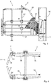
- Fig. 3 illustrates a side view of the animal feeding station 2 and the gate arrangement 4 of Figs. 1 and 2 .
- a head and neck portion of an animal feeding from the feed trough 11 is illustrated in Fig. 3 .
- An abutment between the rotatable member 27 of the actuation member 18 and the neck of the animal is clearly shown in Fig. 3 .
- the gate arrangement 4 comprises a first bar 32 and a second bar 32', see also Fig. 2 , arranged at a distance from each other.
- the actuation member 18 is suspended from the first bar 32 and the second bar 32'.
- the first pivot axis 20 extends between the first bar 32 and the second bar 32'.
- the first bar 32 is connected to the first side section 12 and the second 32' bar is connected to the second side section 12'.
- the gate 13 is pivotably connected at the rear end 8 of the animal feeding station 2.
- the first bar 32 and the second bar 32' are adjustable in height.
- the gate arrangement 4 may be adjusted in size to suit animals of a particular herd or breed.
- the first and second bars 32, 32' are connected with brackets 34 to the first and second side sections 12, 12'.
- other dimensions of the gate arrangement 4 may be adjustable for the same reason.
- the height of the levers 24, 24' above the ground may be adjustable.
- the first and second bars 32, 32', by means of the brackets 34 may the adjustable in forward and rearward directions.
- the linkages 16, 16' may be adjustable in length, as well as the actuation member 18. Once the brackets 34 are tightened, the first and second bars 32, 32' are fixedly connected to the first and second side sections 12, 12'.
- the first and second bars 32, 32' are fixedly connected to the first and second side sections 12, 12'. Due to a resilient member 36 of the linkage 16, discussed further with reference to Figs. 5 and 6 below, an adaptation of an animal space within the feeding station 2 to animals of different lengths in the animal feeding station 2 may be provided. No sliding connection of the actuation member 18 to the first and second side sections 12, 12' is required as in the cage disclosed in FR 2505136 .
- the first and second bars 32, 32', and thus also the first pivot axis 20, may be arranged at a horizontal distance of 9 - 120 cm from the rear end of the animal feeding station.
- the first pivot axis 20 may be arranged at a height of 180 - 200 cm above ground level.
- a distance between the first pivot axis 20, about which the actuation member 18 pivots, and the second pivot axis 26, about which the rotatable member 27 rotates, may be 70 - 135 cm.
- the rotatable member 27 may have a diameter of 10 - 30 cm.
- the actuation member 18 may be pivoted 40 - 60 degrees from a vertical direction towards the feed dispensing arrangement 10 to close the gate 13.
- Fig. 4 illustrates a partial top view of the rear end 8 of the animal feeding station 2 and the gate arrangement 4 of Figs. 1 - 3 .
- the connection between the levers 24, 24'of the gates 13, 13' and the linkages 16, 16' is clearly shown in Fig. 4 .
- the linkage 16 comprises a resilient member 36.
- the further linkage 13' comprises a further resilient member 36'. See further below with reference to Figs. 5 and 6 .
- Fig. 5 illustrates embodiments of a linkage 16 of a gate arrangement to be used in an animal feeding station.
- the linkage 16 At a first end 37 of the linkage 16, the linkage 16 is adapted to be pivotably connected to a gate of the gate arrangement, and at a second end 39 the linkage 16 is adapted to be pivotably connected to an actuation member of the gate arrangement.
- the first end 37 of the linkage 16 is adapted to be pivotably connected to the actuation member, and at the second end 39 the linkage 16 is adapted to be pivotably connected to the gate.
- the linkage 16 comprises a resilient member 36.
- Fig . 6 illustrates a cross section through embodiments of a resilient member 36 of the linkage 16 illustrated in Fig. 5 .
- the resilient member 36 comprises a spring 38.
- a first end 40 of the spring 38 is connected with the gate 13 and a second end 42 of the spring 38 is connected with the actuation member 18.
- the first end 40 of the spring 38 is connected with the actuation member 18 and a second end 42 of the spring 38 is connected with the gate 13.
- the spring 38 comprises a spiral spring 38 and the linkage 16 comprises a cylinder 44 and an arm 46, the cylinder 44 extending around and along the spiral spring 38 and being connected to the first end 40 of the spiral spring 38.
- the arm 46 extends through the spiral spring 38 and the cylinder 44 and is connected to the second end 42 of the spiral spring 38.
- the cylinder 44 is connected to the gate 13 and the arm 46 is connected to the actuation member 18.
- the cylinder 44 is connected to the actuation member 18 and the arm 46 is connected to the gate 13.
- the spiral spring 38 may be compressed inside the cylinder 44 by the arm 46 moving in a direction out of the cylinder 44.
- the linkage 16 may thus be resiliently extended in length. Accordingly, a gate of the gate arrangement being connected to the linkage 16, may resiliently pivot about its substantially vertical third or fourth axis.
- Fig . 7 illustrates embodiments of an animal feeding station 2 comprising a gate arrangement 4.
- the gate arrangement 4 comprises one gate 13 only. Other features of these embodiments find correspondence in the embodiments discussed in connection with in Figs. 1 - 6 .
Description
- The present invention relates to animal feeding stations and to gate arrangements adapted to be used in animal feeding stations.
- Animal feeding stations adapted for feeding animals, such as livestock, with feed are known in the art. Such a feeding station commonly comprises a cubicle for accommodating one animal at a time. A feed dispensing arrangement of the animal feeding station is adapted to dispense a metered portion of feed to an animal in the feeding station.
- Each animal of a herd has a daily ration of feed, such as concentrates, which is fed in metered portions in one or more animal feeding stations to the animals of the herd. Concentrates are highly desirable to livestock. Thus, higher ranked animals of the herd may try to scare lower ranked animals from the animal feeding station.
- To ensure that an animal may feed without it being disturbed in an animal feeding station, the animal feeding station may be provided with a rear gate. The rear gate is closed after an animal has entered the animal feeding station. The rear gate is operated by pneumatic cylinders.
-
FR 2505136 - It is an object of the present invention to provide a robust and uncomplicated gate arrangement adapted to be used in an animal feeding station, and which is gentle to an animal actuating the gate arrangement, and thus is suited for use with livestock, in particular cattle.
- According to an aspect of the invention, the object is achieved by a gate arrangement adapted to be used in an animal feeding station, the gate arrangement comprising a gate arranged to be pivotably suspended, and a gate actuation mechanism. The gate actuation mechanism comprises a linkage and an actuation member. The linkage connects the actuation member with the gate. The actuation member is arranged to be actuated by a neck and/or a back of an animal to pivot the gate via the linkage. The actuation member is suspended to pivot about a substantially horizontal first pivot axis. The actuation member comprises a rotatable member arranged to abut against the neck and/or the back of the animal. The rotatable member is arranged to rotate about a substantially horizontal second pivot axis.
- Since an animal with its neck and/or back actuates the gate via the actuation member and the linkage, and the actuation member comprises a rotatable member, the rotatable member will follow in rotating contact with the neck and/or back of the animal as the animal approaches a feed dispensing arrangement at a front end of a relevant animal feeding station. In this manner the animal will easily and smoothly actuate the actuation member to pivot the gate via the linkage without chafing its neck and/or back. As a result, the above mentioned object is achieved. It is well known that milk producing cattle produce more milk if they feel well in their living environment, of which an animal feeding station forms an often visited part.
- Since an animal with its neck and/or back actuates the gate via the actuation member and the linkage, no pneumatic cylinders or other external actuation devices are required in the animal feeding station according to the invention. The actuation member being actuated by the neck and/or the back of an animal, entails that there is only one main area of contact between the animal and the actuation member. Moreover, since the actuation member is suspended to pivot about a substantially horizontal first pivot axis, the actuation member will be pivoted upwardly by an animal entering a relevant animal feeding station.
- An animal will bow its head as it approaches the feed dispensing arrangement of a relevant animal feeding station. It has been realized by the inventor that this natural tendency of the animal to bow its head may be taken advantage of for ensuring a contact between the neck and/or the back of the animal and the actuation member in an animal feeding station.
- According to embodiments, the rotatable member may comprise bristles. In this manner not only chafing of the neck and/or back of an animal is avoided, but also massage of the neck and/or back of the animal may be provided in a relevant animal feeding station as the animal approaches a feeding dispensing arrangement at a front end of the animal feeding station. Thus, an agreeable feeling may be presented to the animal. Alternatively, the rotatable member may comprise a soft resilient material, such as rubber foam, or plastic foam, which may provide an agreeable feeling to the animal in the same manner as the embodiments comprising a rotatable member with bristles,
- Since an animal visits the animal feeding station a number of times every day, the agreeable feeling provided by the rotatable member comprising bristles and/or a soft resilient material, may contribute to an increased milk production in milk producing cattle feeding from the animal feeding station.
- As opposed to a brush hanging freely in a barn, the rotatable member bristled and/or a soft resilient material provided in an animal feeding station is provided within the confined space provided by the feeding station and the gate of the gate arrangement. Thus, an individual cattle will be massaged by the rotatable member protected within the animal feeding station. Accordingly, lower ranked cattle individuals within a herd may be massaged by the rotatable member without being disturbed by higher ranked animals, as may be the case when the lower ranked animal is brushing against a brush hanging freely in the barn.
- According to embodiments, the linkage may comprise a resilient member. In this manner the linkage may flex. Besides accommodating for animals of different lengths in a relevant animal feeding station, the resilient member also provides a safety feature preventing other animals or humans from being jammed by the gate. Thus, in addition to the gentle treatment of the animal neck and back by the rotatable member, a gentle adaptation to the length of a relevant animal in the anima! feeding station may be provided. Accordingly, a particularly animal friendly gate arrangement may be provided.
- According to embodiments, the gate may comprise a lever and may be pivotable about a substantially vertical third axis. The lever may be connected to the linkage, and the linkage may be connected to the actuation member between the first pivot axis and the second pivot axis. In this manner an actuation of the actuation member may be transferred via the linkage to the gate to pivot the gate about the third axis.
- According to embodiments, the gate arrangement may comprise a further gate arranged to be pivotably suspended. The gate actuation mechanism may comprises a further linkage and the further linkage may connect the actuation member with the further gate, In this manner two gates actuated by the actuation member may be provided at a relevant animal feeding station.
- According to a further aspect of the invention, there is provided an animal feeding station having a front end and a rear end, the feeding station comprising a feed dispensing arrangement arranged at the front end, a first side section and a second side section extending at a distance from each other, from the feed dispensing arrangement to the rear end defining there between a single animal feeding space. The animal feeding station comprises a gate arrangement according to aspects and/or embodiments disclosed herein.
- According to embodiments, the gate arrangement of the animal feeding station may comprise one gate only.
- According to other embodiments, the gate arrangement of the animal feeding station may comprise two gates as disclosed in some embodiments herein.
- Further features of, and advantages with, the present invention will become apparent when studying the appended claims and the following detailed description.
- Various aspects of the invention, including its particular features and advantages, will be readily understood from the example embodiments discussed in the following detailed description and the accompanying drawings, in which:
-
Fig. 1 illustrates embodiments of an animal feeding station comprising a gate arrangement, -
Fig. 2 illustrates the embodiments of the animal feeding station ofFig. 1 with a gate in a closed position, -
Fig. 3 illustrates a side view of the animal feeding station and the gate arrangement ofFigs. 1 and 2 , -
Fig. 4 illustrates a partial top view of a rear end of the animal feeding station and the gate arrangement ofFigs. 1 - 3 , -
Fig. 5 illustrates embodiments of a linkage of a gate arrangement to be used in an animal feeding station, -
Fig. 6 illustrates a cross section through embodiments of a resilient member of the linkage illustrated inFig. 5 , -
Fig. 7 illustrates embodiments of an animal feeding station comprising a gate arrangement, and -
Fig. 8 illustrates a rotatable member according to embodiments. - In the context of various embodiments of animal feeding stations, aspects of the present invention relating on the one hand to embodiments of animal feeding stations, and on the other hand to embodiments of gate arrangements adapted to be used in animal feeding stations, will now be described more fully. Like numbers refer to like elements throughout. Well-known functions or constructions will not necessarily be described in detail for brevity and/or clarity.
-
Fig. 1 illustrates embodiments of ananimal feeding station 2 comprising agate arrangement 4. Theanimal feeding station 2 has afront end 6 and arear end 8. Theanimal feeding station 2 comprises afeed dispensing arrangement 10 arranged at thefront end 6. Thefeed dispensing arrangement 10 comprises afeed trough 11. Afirst side section 12 and a second side section 12' extend at a distance from each other from thefeed dispensing arrangement 10 to therear end 8 defining there between a single animal feeding space. - The
gate arrangement 4 comprises agate 13 pivotably suspended at therear end 8 of theanimal feeding station 2, and agate actuation mechanism 14. Thegate actuation mechanism 14 comprises alinkage 16 and anactuation member 18. Thelinkage 16 connects theactuation member 18 with thegate 13. Theactuation member 18 is arranged to be actuated by a neck and/or a back of an animal in the animal feeding station to pivot thegate 13 via thelinkages 16 to close thegate 13. - In
Fig. 1 thegate 13 is illustrated in an open position. -
Fig. 2 illustrates the embodiments of theanimal feeding station 2 ofFig. 1 with thegate 13 illustrated in a closed position, as pivoted by thelinkage 16 and theactuation member 18 by a neck and/or a back of a non-shown animal in theanimal feeding station 2. In the following reference will be made to bothFig. 2 and Fig. 1 . - The
actuation member 18 is suspended to pivot about a substantially horizontalfirst pivot axis 20. Thefirst pivot axis 20 is arranged above animal height in theanimal feeding station 2. As shown inFig. 2 theactuation member 18 has been pivoted upwardly by the non-shown animal in theanimal feeding station 2. Thegate 13 is pivotable about a substantially verticalthird axis 22. Thegate 13 comprises alever 24, whichlever 24 when actuated pivots thegate 13 about the substantially verticalthird axis 22. Thelever 24 is connected to thelinkage 16. Thelinkage 16 is connected to theactuation member 18 between thefirst pivot axis 20 and asecond pivot axis 26. Thesecond pivot axis 26 relates to arotatable member 27 of theactuation member 18. - An actuation of the
actuation member 18 is transferred via thelinkage 16 to thegate 13 to pivot the gate about thethird axis 22. Thegate 13 is closed by an animal when it lifts theactuation member 18 with its neck and/or back to pivot about thefirst pivot axis 20. Thegate 13 is opened when the animal backs out of theanimal feeding station 2. In this situation gravity and the weight of theactuation member 18 forces thegate 13 to open. - As mentioned above, the
actuation member 18 comprises arotatable member 27. Therotatable member 27 is arranged to abut against the neck and/or the back of an animal in theanimal feeding station 2. Therotatable member 27 is arranged to rotate about the substantially horizontalsecond pivot axis 26. Theactuation member 18 comprisesbar members 29, 29' extending between thefirst pivot axis 20 and thesecond pivot axis 26. - The
rotatable member 27 comprisesbristles 28. Thebristles 28 will provide an agreeable feeling to the animal and provide a certain degree of resilience to therotatable member 27 and theactuation member 18. According to example embodiments, thebristles 28 may be made from a nylon material, such as nylon pa6, having a diameter within a range of 0,8 - 1,5 mm and a length within a range of 20 - 50 mm. It has been found that such bristles are durable enough to stand the strain over longer periods of time as therotatable member 27 is subjected to animals bearing with their necks and/or the backs against of therotatable member 27. - A
rotatable member 27 according to alternative embodiments is illustrated inFig. 8 . Therotatable member 27 comprises a soft resilient material. For instance, therotatable member 27 may comprise a cylinder made from a rubber foam material or a plastic foam material. - Returning to
Figs. 1 and 2 , thegate arrangement 4 comprises a further gate 13' pivotably suspended at therear end 8 of theanimal feeding station 2. Thegate actuation mechanism 14 comprises a further linkage 16'. The further linkage 16' connects theactuation member 18 with the further gate 13'. Bothgates 13, 13' are thus actuated by theactuation member 18. - The further gate 13' comprises a further lever 24' and is pivotable about a substantially vertical
fourth axis 30. The further lever 24' is connected to the further linkage 16'. -
Fig. 3 illustrates a side view of theanimal feeding station 2 and thegate arrangement 4 ofFigs. 1 and 2 . A head and neck portion of an animal feeding from thefeed trough 11 is illustrated inFig. 3 . An abutment between therotatable member 27 of theactuation member 18 and the neck of the animal is clearly shown inFig. 3 . - The
gate arrangement 4 comprises afirst bar 32 and a second bar 32', see alsoFig. 2 , arranged at a distance from each other. Theactuation member 18 is suspended from thefirst bar 32 and the second bar 32'. Thefirst pivot axis 20 extends between thefirst bar 32 and the second bar 32'. Thefirst bar 32 is connected to thefirst side section 12 and the second 32' bar is connected to the second side section 12'. Thegate 13 is pivotably connected at therear end 8 of theanimal feeding station 2. - The
first bar 32 and the second bar 32' are adjustable in height. Thus, thegate arrangement 4 may be adjusted in size to suit animals of a particular herd or breed. For this purpose the first andsecond bars 32, 32' are connected withbrackets 34 to the first andsecond side sections 12, 12'. Also other dimensions of thegate arrangement 4 may be adjustable for the same reason. The height of thelevers 24, 24' above the ground may be adjustable. The first andsecond bars 32, 32', by means of thebrackets 34, may the adjustable in forward and rearward directions. Thelinkages 16, 16' may be adjustable in length, as well as theactuation member 18. Once thebrackets 34 are tightened, the first andsecond bars 32, 32' are fixedly connected to the first andsecond side sections 12, 12'. - The first and
second bars 32, 32' are fixedly connected to the first andsecond side sections 12, 12'. Due to aresilient member 36 of thelinkage 16, discussed further with reference toFigs. 5 and 6 below, an adaptation of an animal space within the feedingstation 2 to animals of different lengths in theanimal feeding station 2 may be provided. No sliding connection of theactuation member 18 to the first andsecond side sections 12, 12' is required as in the cage disclosed inFR 2505136 - Provided purely as an example, the following main dimensions are mentioned: The first and
second bars 32, 32', and thus also thefirst pivot axis 20, may be arranged at a horizontal distance of 9 - 120 cm from the rear end of the animal feeding station. Thefirst pivot axis 20 may be arranged at a height of 180 - 200 cm above ground level. A distance between thefirst pivot axis 20, about which theactuation member 18 pivots, and thesecond pivot axis 26, about which therotatable member 27 rotates, may be 70 - 135 cm. Therotatable member 27 may have a diameter of 10 - 30 cm. Theactuation member 18 may be pivoted 40 - 60 degrees from a vertical direction towards thefeed dispensing arrangement 10 to close thegate 13. -
Fig. 4 illustrates a partial top view of therear end 8 of theanimal feeding station 2 and thegate arrangement 4 ofFigs. 1 - 3 . The connection between thelevers 24, 24'of thegates 13, 13' and thelinkages 16, 16' is clearly shown inFig. 4 .
Thelinkage 16 comprises aresilient member 36. Similarly, the further linkage 13' comprises a further resilient member 36'. See further below with reference toFigs. 5 and 6 . -
Fig. 5 illustrates embodiments of alinkage 16 of a gate arrangement to be used in an animal feeding station. At afirst end 37 of thelinkage 16, thelinkage 16 is adapted to be pivotably connected to a gate of the gate arrangement, and at asecond end 39 thelinkage 16 is adapted to be pivotably connected to an actuation member of the gate arrangement. Alternatively, thefirst end 37 of thelinkage 16 is adapted to be pivotably connected to the actuation member, and at thesecond end 39 thelinkage 16 is adapted to be pivotably connected to the gate. Thelinkage 16 comprises aresilient member 36. -
Fig. 6 illustrates a cross section through embodiments of aresilient member 36 of thelinkage 16 illustrated inFig. 5 . Theresilient member 36 comprises aspring 38. Afirst end 40 of thespring 38 is connected with thegate 13 and asecond end 42 of thespring 38 is connected with theactuation member 18. Alternatively, thefirst end 40 of thespring 38 is connected with theactuation member 18 and asecond end 42 of thespring 38 is connected with thegate 13. More specifically, thespring 38 comprises aspiral spring 38 and thelinkage 16 comprises acylinder 44 and anarm 46, thecylinder 44 extending around and along thespiral spring 38 and being connected to thefirst end 40 of thespiral spring 38. Thearm 46 extends through thespiral spring 38 and thecylinder 44 and is connected to thesecond end 42 of thespiral spring 38. Thecylinder 44 is connected to thegate 13 and thearm 46 is connected to theactuation member 18. Alternatively, thecylinder 44 is connected to theactuation member 18 and thearm 46 is connected to thegate 13. - In operation, the
spiral spring 38 may be compressed inside thecylinder 44 by thearm 46 moving in a direction out of thecylinder 44. Thelinkage 16 may thus be resiliently extended in length. Accordingly, a gate of the gate arrangement being connected to thelinkage 16, may resiliently pivot about its substantially vertical third or fourth axis. -
Fig. 7 illustrates embodiments of ananimal feeding station 2 comprising agate arrangement 4. Thegate arrangement 4 comprises onegate 13 only. Other features of these embodiments find correspondence in the embodiments discussed in connection with inFigs. 1 - 6 . - This invention should not be construed as limited to the embodiments set forth herein. A person skilled in the art will realize that different features of the embodiments disclosed herein may be combined to create embodiments other than those described herein, without departing from the scope of the present invention, as defined by the appended claims. For instance, the
gate 13 may be pivotable about a horizontal axis arranged at a height above the animal instead of about a vertical axis. Although the invention has been described with reference to example embodiments, many different alterations, modifications and the like will become apparent for those skilled in the art. Therefore, it is to be understood that the foregoing is illustrative of various example embodiments and that the invention is defined only by the appended claims. - As used herein, the term "comprising" or "comprises" is open-ended, and includes one or more stated features, elements, steps, components or functions but does not preclude the presence or addition of one or more other features, elements, steps, components, functions or groups thereof.
Claims (15)
- A gate arrangement (4) adapted to be used in an animal feeding station (2), the gate arrangement (4) comprising a gate (13) arranged to be pivotably suspended, and a gate actuation mechanism (14), wherein the gate actuation mechanism (14) comprises a linkage (16) and an actuation member (18), wherein the linkage (16) connects the actuation member (18) with the gate (13), wherein the actuation member (18) is arranged to be actuated by a neck and/or a back of an animal to pivot the gate (13) via the linkage (16), and wherein the actuation member (18) is suspended to pivot about a substantially horizontal first pivot axis (20), characterised in that
the actuation member (18) comprises a rotatable member (27) arranged to abut against the neck and/or the back of the animal, the rotatable member (27) being arranged to rotate about a substantially horizontal second pivot axis (26). - The gate arrangement (4) according to claim 1, wherein the rotatable member (27) comprises bristles (28), preferably bristles made from nylon having a diameter within a range of 0,8 - 1,5 mm and a length within a range of 20 - 50 mm.
- The gate arrangement (4) according to claim 1, wherein the rotatable member comprises a soft resilient material.
- The gate arrangement (4) according to any one of the preceding claims, comprising a first bar (32) and a second bar (32') arranged at a distance from each other, wherein the actuation member (18) is suspended from the first bar (32) and the second bar(32'), the first pivot axis (20) extending between the first bar (32) and the second bar (32').
- The gate arrangement (4) according to claim 4, wherein the first bar (32) and the second bar (32') are adjustable in height.
- The gate arrangement (4) according to any one of the preceding claims, wherein the linkage (16) comprises a resilient member (36).
- The gate arrangement (4) according to claim 6, wherein the resilient member (36) comprises a spring (38), and wherein a first end (40) of the spring (38) is connected with the gate (13) and a second end (42) of the spring (38) is connected with the actuation member (18), or wherein the first end (40) of the spring (38) is connected with the actuation member (18) and a second end (42) of the spring (38) is connected with the gate (13).
- The gate arrangement (4) according to claim 7, wherein the spring (38) comprises a spiral spring (38) and the linkage (16) comprises a cylinder (44) and an arm (46), the cylinder (44) extending around and along the spiral spring (38) and being connected to the first end (40) of the spiral spring (38), wherein the arm (46) extends through the spiral spring (38) and the cylinder (44) and is connected to the second end (42) of the spiral spring (38), and wherein the cylinder (44) is connected to the gate (13) and the arm (46) is connected to the actuation member (18), or wherein the cylinder (44) is connected to the actuation member (18) and the arm (46) is connected to the gate (13).
- The gate arrangement (4) according to any one of the preceding claims, wherein the gate (13) comprises a lever (24) and is pivotable about a substantially vertical third axis (22), the lever (24) being connected to the linkage (16), and wherein the linkage (16) is connected to the actuation member (18) between the first pivot axis (20) and the second pivot axis (26).
- The gate arrangement (4) according to any one of the preceding claims, comprising a further gate (13') arranged to be pivotably suspended, wherein the gate actuation mechanism (14) comprises a further linkage (16'), and wherein the further linkage (16') connects the actuation member (18) with the further gate (13').
- The gate arrangement (4) according to claim 10, wherein the further gate (13') comprises a further lever (24') and is pivotable about a substantially vertical fourth axis (30), the further lever (24') being connected to the further linkage (16').
- The gate arrangement (4) according to claim 10 or 11, wherein further linkage (16') comprises a further resilient member (36').
- An animal feeding station (2) having a front end and (6) a rear end (8), the animal feeding station (2) comprising a feed dispensing arrangement (10) arranged at the front end (6), a first side section (12) and a second side section (12') extending at a distance from each other from the feed dispensing arrangement (10) to the rear end (8) defining there between a single animal feeding space,
characterized in that the animal feeding station (2) comprises a gate arrangement (4) according to any one of claims 1 - 9. - The animal feeding station (2) according to claim 13, wherein the gate arrangement (4) comprises one gate (13) only.
- The animal feeding station (2) according to claim 13, comprising the gate arrangement (4) according to any one of claims 10 - 12.
Priority Applications (1)
| Application Number | Priority Date | Filing Date | Title |
|---|---|---|---|
| PL14793649T PL3057408T3 (en) | 2013-10-14 | 2014-10-13 | Gate arrangement and animal feeding station |
Applications Claiming Priority (2)
| Application Number | Priority Date | Filing Date | Title |
|---|---|---|---|
| SE1351215 | 2013-10-14 | ||
| PCT/SE2014/051208 WO2015057141A1 (en) | 2013-10-14 | 2014-10-13 | Gate arrangement and animal feeding station |
Publications (2)
| Publication Number | Publication Date |
|---|---|
| EP3057408A1 EP3057408A1 (en) | 2016-08-24 |
| EP3057408B1 true EP3057408B1 (en) | 2017-06-28 |
Family
ID=51862512
Family Applications (1)
| Application Number | Title | Priority Date | Filing Date |
|---|---|---|---|
| EP14793649.6A Active EP3057408B1 (en) | 2013-10-14 | 2014-10-13 | Gate arrangement and animal feeding station |
Country Status (3)
| Country | Link |
|---|---|
| EP (1) | EP3057408B1 (en) |
| PL (1) | PL3057408T3 (en) |
| WO (1) | WO2015057141A1 (en) |
Families Citing this family (4)
| Publication number | Priority date | Publication date | Assignee | Title |
|---|---|---|---|---|
| NL2012901B1 (en) * | 2014-05-28 | 2016-05-03 | Richard De Boer Abel | Door for closing off a room for keeping cattle and a feeding box with a door. |
| CN106962215A (en) * | 2017-05-08 | 2017-07-21 | 湖南美奕机电科技有限公司 | Pig drawing-in device |
| CN107711548B (en) * | 2017-09-14 | 2022-11-15 | 中国农业科学院北京畜牧兽医研究所 | Electronic feeding station for pregnant sows |
| CN108309496B (en) * | 2018-03-21 | 2023-06-20 | 青岛农业大学 | Fixing device for pigs |
Family Cites Families (6)
| Publication number | Priority date | Publication date | Assignee | Title |
|---|---|---|---|---|
| US3785346A (en) * | 1972-08-22 | 1974-01-15 | J Dower | Stalls for animals and gate assemblies therefor |
| FR2505136A1 (en) | 1981-05-07 | 1982-11-12 | Pencole Gerard | Protection system for pig feeding pen - uses swinging doors blocked by feeding pig, preventing entry of other pigs |
| NL1016183C2 (en) * | 2000-09-14 | 2002-03-15 | Prolion Bv | Milking stall for cows, has automatic rotating abrasive brush mechanism to calm animal by rubbing area of back |
| SE531033C2 (en) * | 2007-02-28 | 2008-11-25 | Delaval Holding Ab | A rotating stable for automatic milking of animals |
| DE102008016591A1 (en) * | 2008-03-31 | 2009-10-01 | Gea Westfaliasurge Gmbh | Exit gate for a milking parlor and milking parlor |
| DK177280B1 (en) * | 2011-04-07 | 2012-09-24 | Egebjerg Internat A S | Pet booths, preferably lakes, with elastic connecting rod |
-
2014
- 2014-10-13 WO PCT/SE2014/051208 patent/WO2015057141A1/en active Application Filing
- 2014-10-13 PL PL14793649T patent/PL3057408T3/en unknown
- 2014-10-13 EP EP14793649.6A patent/EP3057408B1/en active Active
Non-Patent Citations (1)
| Title |
|---|
| None * |
Also Published As
| Publication number | Publication date |
|---|---|
| WO2015057141A1 (en) | 2015-04-23 |
| EP3057408A1 (en) | 2016-08-24 |
| PL3057408T3 (en) | 2017-10-31 |
Similar Documents
| Publication | Publication Date | Title |
|---|---|---|
| EP3057408B1 (en) | Gate arrangement and animal feeding station | |
| McGreevy et al. | Roles of learning theory and ethology in equitation | |
| Grandin | Handling methods and facilities to reduce stress on cattle | |
| JPH11506303A (en) | Livestock management device and management method | |
| EP2149297A2 (en) | Animal muzzle | |
| US8707909B2 (en) | Blind animal halo guide | |
| CN205585009U (en) | Compartment of milking | |
| US20170215383A1 (en) | Clamshell sensory headgear for a pet | |
| US10477830B2 (en) | Flexible neckrail coupling | |
| US11485628B2 (en) | Grazing restrictor | |
| Stefanowska et al. | Dairy cow interactions with an automatic milking system starting withwalk-through'selection | |
| WO2019074970A1 (en) | An improved equine blanket and adjustable blanket system | |
| KR20060109015A (en) | Device for collecting pet's excrement | |
| US8210130B1 (en) | Audible prod for livestock | |
| JP6960072B2 (en) | Animal walking aid | |
| GB2569988A (en) | An improved animal dwelling ventilation system, in particular for horse stables | |
| KR200351895Y1 (en) | A stanchion for cowshed possible individual meals by ID(identification) | |
| RU182032U1 (en) | SWIVEL ASSEMBLY FOR FASTENING CERVICAL PIPE OF THE FEED TABLE | |
| RU182036U1 (en) | STALL EQUIPMENT | |
| WO2007058529A3 (en) | Feed barrier for livestock | |
| Glavić et al. | Protection and Animal Welfare in Farming Practices for Milk Production in Region of Northeastern Bosnia and Herzegovina | |
| US260948A (en) | Muzzle | |
| KR200468977Y1 (en) | The structure of horse feed | |
| Zejdová | SYSTEM OF ACTIVE STABLING FOR HORSES | |
| Horwitz | Communication, social behavior, and enrichment in cats. |
Legal Events
| Date | Code | Title | Description |
|---|---|---|---|
| PUAI | Public reference made under article 153(3) epc to a published international application that has entered the european phase |
Free format text: ORIGINAL CODE: 0009012 |
|
| 17P | Request for examination filed |
Effective date: 20160502 |
|
| AK | Designated contracting states |
Kind code of ref document: A1 Designated state(s): AL AT BE BG CH CY CZ DE DK EE ES FI FR GB GR HR HU IE IS IT LI LT LU LV MC MK MT NL NO PL PT RO RS SE SI SK SM TR |
|
| AX | Request for extension of the european patent |
Extension state: BA ME |
|
| TPAC | Observations filed by third parties |
Free format text: ORIGINAL CODE: EPIDOSNTIPA |
|
| DAX | Request for extension of the european patent (deleted) | ||
| GRAP | Despatch of communication of intention to grant a patent |
Free format text: ORIGINAL CODE: EPIDOSNIGR1 |
|
| INTG | Intention to grant announced |
Effective date: 20170221 |
|
| GRAS | Grant fee paid |
Free format text: ORIGINAL CODE: EPIDOSNIGR3 |
|
| GRAA | (expected) grant |
Free format text: ORIGINAL CODE: 0009210 |
|
| AK | Designated contracting states |
Kind code of ref document: B1 Designated state(s): AL AT BE BG CH CY CZ DE DK EE ES FI FR GB GR HR HU IE IS IT LI LT LU LV MC MK MT NL NO PL PT RO RS SE SI SK SM TR |
|
| REG | Reference to a national code |
Ref country code: GB Ref legal event code: FG4D |
|
| REG | Reference to a national code |
Ref country code: CH Ref legal event code: EP |
|
| REG | Reference to a national code |
Ref country code: AT Ref legal event code: REF Ref document number: 904012 Country of ref document: AT Kind code of ref document: T Effective date: 20170715 |
|
| REG | Reference to a national code |
Ref country code: IE Ref legal event code: FG4D |
|
| REG | Reference to a national code |
Ref country code: NL Ref legal event code: FP |
|
| REG | Reference to a national code |
Ref country code: DE Ref legal event code: R096 Ref document number: 602014011354 Country of ref document: DE |
|
| REG | Reference to a national code |
Ref country code: NO Ref legal event code: T2 Effective date: 20170628 |
|
| PG25 | Lapsed in a contracting state [announced via postgrant information from national office to epo] |
Ref country code: GR Free format text: LAPSE BECAUSE OF FAILURE TO SUBMIT A TRANSLATION OF THE DESCRIPTION OR TO PAY THE FEE WITHIN THE PRESCRIBED TIME-LIMIT Effective date: 20170929 Ref country code: LT Free format text: LAPSE BECAUSE OF FAILURE TO SUBMIT A TRANSLATION OF THE DESCRIPTION OR TO PAY THE FEE WITHIN THE PRESCRIBED TIME-LIMIT Effective date: 20170628 Ref country code: HR Free format text: LAPSE BECAUSE OF FAILURE TO SUBMIT A TRANSLATION OF THE DESCRIPTION OR TO PAY THE FEE WITHIN THE PRESCRIBED TIME-LIMIT Effective date: 20170628 |
|
| REG | Reference to a national code |
Ref country code: LT Ref legal event code: MG4D |
|
| REG | Reference to a national code |
Ref country code: AT Ref legal event code: MK05 Ref document number: 904012 Country of ref document: AT Kind code of ref document: T Effective date: 20170628 |
|
| PG25 | Lapsed in a contracting state [announced via postgrant information from national office to epo] |
Ref country code: SE Free format text: LAPSE BECAUSE OF FAILURE TO SUBMIT A TRANSLATION OF THE DESCRIPTION OR TO PAY THE FEE WITHIN THE PRESCRIBED TIME-LIMIT Effective date: 20170628 Ref country code: RS Free format text: LAPSE BECAUSE OF FAILURE TO SUBMIT A TRANSLATION OF THE DESCRIPTION OR TO PAY THE FEE WITHIN THE PRESCRIBED TIME-LIMIT Effective date: 20170628 Ref country code: LV Free format text: LAPSE BECAUSE OF FAILURE TO SUBMIT A TRANSLATION OF THE DESCRIPTION OR TO PAY THE FEE WITHIN THE PRESCRIBED TIME-LIMIT Effective date: 20170628 Ref country code: BG Free format text: LAPSE BECAUSE OF FAILURE TO SUBMIT A TRANSLATION OF THE DESCRIPTION OR TO PAY THE FEE WITHIN THE PRESCRIBED TIME-LIMIT Effective date: 20170928 |
|
| PG25 | Lapsed in a contracting state [announced via postgrant information from national office to epo] |
Ref country code: EE Free format text: LAPSE BECAUSE OF FAILURE TO SUBMIT A TRANSLATION OF THE DESCRIPTION OR TO PAY THE FEE WITHIN THE PRESCRIBED TIME-LIMIT Effective date: 20170628 Ref country code: RO Free format text: LAPSE BECAUSE OF FAILURE TO SUBMIT A TRANSLATION OF THE DESCRIPTION OR TO PAY THE FEE WITHIN THE PRESCRIBED TIME-LIMIT Effective date: 20170628 Ref country code: CZ Free format text: LAPSE BECAUSE OF FAILURE TO SUBMIT A TRANSLATION OF THE DESCRIPTION OR TO PAY THE FEE WITHIN THE PRESCRIBED TIME-LIMIT Effective date: 20170628 Ref country code: SK Free format text: LAPSE BECAUSE OF FAILURE TO SUBMIT A TRANSLATION OF THE DESCRIPTION OR TO PAY THE FEE WITHIN THE PRESCRIBED TIME-LIMIT Effective date: 20170628 Ref country code: AT Free format text: LAPSE BECAUSE OF FAILURE TO SUBMIT A TRANSLATION OF THE DESCRIPTION OR TO PAY THE FEE WITHIN THE PRESCRIBED TIME-LIMIT Effective date: 20170628 |
|
| PG25 | Lapsed in a contracting state [announced via postgrant information from national office to epo] |
Ref country code: ES Free format text: LAPSE BECAUSE OF FAILURE TO SUBMIT A TRANSLATION OF THE DESCRIPTION OR TO PAY THE FEE WITHIN THE PRESCRIBED TIME-LIMIT Effective date: 20170628 Ref country code: IT Free format text: LAPSE BECAUSE OF FAILURE TO SUBMIT A TRANSLATION OF THE DESCRIPTION OR TO PAY THE FEE WITHIN THE PRESCRIBED TIME-LIMIT Effective date: 20170628 Ref country code: IS Free format text: LAPSE BECAUSE OF FAILURE TO SUBMIT A TRANSLATION OF THE DESCRIPTION OR TO PAY THE FEE WITHIN THE PRESCRIBED TIME-LIMIT Effective date: 20171028 Ref country code: SM Free format text: LAPSE BECAUSE OF FAILURE TO SUBMIT A TRANSLATION OF THE DESCRIPTION OR TO PAY THE FEE WITHIN THE PRESCRIBED TIME-LIMIT Effective date: 20170628 |
|
| REG | Reference to a national code |
Ref country code: DE Ref legal event code: R097 Ref document number: 602014011354 Country of ref document: DE |
|
| PG25 | Lapsed in a contracting state [announced via postgrant information from national office to epo] |
Ref country code: DK Free format text: LAPSE BECAUSE OF FAILURE TO SUBMIT A TRANSLATION OF THE DESCRIPTION OR TO PAY THE FEE WITHIN THE PRESCRIBED TIME-LIMIT Effective date: 20170628 |
|
| PLBE | No opposition filed within time limit |
Free format text: ORIGINAL CODE: 0009261 |
|
| STAA | Information on the status of an ep patent application or granted ep patent |
Free format text: STATUS: NO OPPOSITION FILED WITHIN TIME LIMIT |
|
| PG25 | Lapsed in a contracting state [announced via postgrant information from national office to epo] |
Ref country code: MC Free format text: LAPSE BECAUSE OF FAILURE TO SUBMIT A TRANSLATION OF THE DESCRIPTION OR TO PAY THE FEE WITHIN THE PRESCRIBED TIME-LIMIT Effective date: 20170628 |
|
| REG | Reference to a national code |
Ref country code: CH Ref legal event code: PL |
|
| 26N | No opposition filed |
Effective date: 20180329 |
|
| REG | Reference to a national code |
Ref country code: IE Ref legal event code: MM4A |
|
| REG | Reference to a national code |
Ref country code: FR Ref legal event code: ST Effective date: 20180629 |
|
| PG25 | Lapsed in a contracting state [announced via postgrant information from national office to epo] |
Ref country code: LI Free format text: LAPSE BECAUSE OF NON-PAYMENT OF DUE FEES Effective date: 20171031 Ref country code: CH Free format text: LAPSE BECAUSE OF NON-PAYMENT OF DUE FEES Effective date: 20171031 |
|
| PG25 | Lapsed in a contracting state [announced via postgrant information from national office to epo] |
Ref country code: FR Free format text: LAPSE BECAUSE OF NON-PAYMENT OF DUE FEES Effective date: 20171031 Ref country code: SI Free format text: LAPSE BECAUSE OF FAILURE TO SUBMIT A TRANSLATION OF THE DESCRIPTION OR TO PAY THE FEE WITHIN THE PRESCRIBED TIME-LIMIT Effective date: 20170628 |
|
| PG25 | Lapsed in a contracting state [announced via postgrant information from national office to epo] |
Ref country code: MT Free format text: LAPSE BECAUSE OF NON-PAYMENT OF DUE FEES Effective date: 20171013 |
|
| PG25 | Lapsed in a contracting state [announced via postgrant information from national office to epo] |
Ref country code: IE Free format text: LAPSE BECAUSE OF NON-PAYMENT OF DUE FEES Effective date: 20171013 |
|
| GBPC | Gb: european patent ceased through non-payment of renewal fee |
Effective date: 20181013 |
|
| PG25 | Lapsed in a contracting state [announced via postgrant information from national office to epo] |
Ref country code: HU Free format text: LAPSE BECAUSE OF FAILURE TO SUBMIT A TRANSLATION OF THE DESCRIPTION OR TO PAY THE FEE WITHIN THE PRESCRIBED TIME-LIMIT; INVALID AB INITIO Effective date: 20141013 |
|
| PG25 | Lapsed in a contracting state [announced via postgrant information from national office to epo] |
Ref country code: GB Free format text: LAPSE BECAUSE OF NON-PAYMENT OF DUE FEES Effective date: 20181013 Ref country code: CY Free format text: LAPSE BECAUSE OF FAILURE TO SUBMIT A TRANSLATION OF THE DESCRIPTION OR TO PAY THE FEE WITHIN THE PRESCRIBED TIME-LIMIT Effective date: 20170628 |
|
| PG25 | Lapsed in a contracting state [announced via postgrant information from national office to epo] |
Ref country code: MK Free format text: LAPSE BECAUSE OF FAILURE TO SUBMIT A TRANSLATION OF THE DESCRIPTION OR TO PAY THE FEE WITHIN THE PRESCRIBED TIME-LIMIT Effective date: 20170628 |
|
| PG25 | Lapsed in a contracting state [announced via postgrant information from national office to epo] |
Ref country code: PT Free format text: LAPSE BECAUSE OF FAILURE TO SUBMIT A TRANSLATION OF THE DESCRIPTION OR TO PAY THE FEE WITHIN THE PRESCRIBED TIME-LIMIT Effective date: 20170628 |
|
| PG25 | Lapsed in a contracting state [announced via postgrant information from national office to epo] |
Ref country code: AL Free format text: LAPSE BECAUSE OF FAILURE TO SUBMIT A TRANSLATION OF THE DESCRIPTION OR TO PAY THE FEE WITHIN THE PRESCRIBED TIME-LIMIT Effective date: 20170628 |
|
| PGFP | Annual fee paid to national office [announced via postgrant information from national office to epo] |
Ref country code: NL Payment date: 20230915 Year of fee payment: 10 Ref country code: LU Payment date: 20230927 Year of fee payment: 10 |
|
| PGFP | Annual fee paid to national office [announced via postgrant information from national office to epo] |
Ref country code: PL Payment date: 20230913 Year of fee payment: 10 Ref country code: BE Payment date: 20230918 Year of fee payment: 10 |
|
| PGFP | Annual fee paid to national office [announced via postgrant information from national office to epo] |
Ref country code: TR Payment date: 20231011 Year of fee payment: 10 Ref country code: NO Payment date: 20231010 Year of fee payment: 10 Ref country code: FI Payment date: 20231011 Year of fee payment: 10 Ref country code: DE Payment date: 20230906 Year of fee payment: 10 |