EP3057309A1 - Method for controlling camera system, electronic device, and storage medium - Google Patents
Method for controlling camera system, electronic device, and storage medium Download PDFInfo
- Publication number
- EP3057309A1 EP3057309A1 EP16155005.8A EP16155005A EP3057309A1 EP 3057309 A1 EP3057309 A1 EP 3057309A1 EP 16155005 A EP16155005 A EP 16155005A EP 3057309 A1 EP3057309 A1 EP 3057309A1
- Authority
- EP
- European Patent Office
- Prior art keywords
- electronic device
- camera system
- camera
- display
- image
- Prior art date
- Legal status (The legal status is an assumption and is not a legal conclusion. Google has not performed a legal analysis and makes no representation as to the accuracy of the status listed.)
- Granted
Links
- 238000000034 method Methods 0.000 title claims abstract description 141
- 230000015654 memory Effects 0.000 claims description 168
- 238000001514 detection method Methods 0.000 claims description 27
- 230000003993 interaction Effects 0.000 claims 2
- 238000012545 processing Methods 0.000 description 243
- 230000004044 response Effects 0.000 description 45
- 238000004891 communication Methods 0.000 description 44
- 230000006870 function Effects 0.000 description 40
- 230000008569 process Effects 0.000 description 37
- 238000010586 diagram Methods 0.000 description 25
- 230000001413 cellular effect Effects 0.000 description 17
- 230000003287 optical effect Effects 0.000 description 10
- 238000012937 correction Methods 0.000 description 7
- 230000005540 biological transmission Effects 0.000 description 6
- 230000014509 gene expression Effects 0.000 description 6
- 230000009467 reduction Effects 0.000 description 5
- 239000008186 active pharmaceutical agent Substances 0.000 description 4
- 230000008859 change Effects 0.000 description 4
- 230000005611 electricity Effects 0.000 description 4
- 230000033001 locomotion Effects 0.000 description 4
- 238000003825 pressing Methods 0.000 description 4
- 238000010079 rubber tapping Methods 0.000 description 4
- 230000001133 acceleration Effects 0.000 description 3
- 230000000694 effects Effects 0.000 description 3
- 230000036541 health Effects 0.000 description 3
- 238000005286 illumination Methods 0.000 description 3
- 238000005259 measurement Methods 0.000 description 3
- 230000009471 action Effects 0.000 description 2
- 230000008901 benefit Effects 0.000 description 2
- 239000008280 blood Substances 0.000 description 2
- 210000004369 blood Anatomy 0.000 description 2
- 238000006243 chemical reaction Methods 0.000 description 2
- 238000002591 computed tomography Methods 0.000 description 2
- 238000003384 imaging method Methods 0.000 description 2
- 239000004973 liquid crystal related substance Substances 0.000 description 2
- 230000003252 repetitive effect Effects 0.000 description 2
- 239000004065 semiconductor Substances 0.000 description 2
- XLYOFNOQVPJJNP-UHFFFAOYSA-N water Substances O XLYOFNOQVPJJNP-UHFFFAOYSA-N 0.000 description 2
- 229920001621 AMOLED Polymers 0.000 description 1
- 238000002583 angiography Methods 0.000 description 1
- 238000003491 array Methods 0.000 description 1
- 238000013473 artificial intelligence Methods 0.000 description 1
- 238000009530 blood pressure measurement Methods 0.000 description 1
- 238000009529 body temperature measurement Methods 0.000 description 1
- 238000004364 calculation method Methods 0.000 description 1
- 230000010267 cellular communication Effects 0.000 description 1
- 230000000295 complement effect Effects 0.000 description 1
- 238000004590 computer program Methods 0.000 description 1
- 239000004020 conductor Substances 0.000 description 1
- 238000010276 construction Methods 0.000 description 1
- 238000011161 development Methods 0.000 description 1
- -1 electricity Substances 0.000 description 1
- 238000002567 electromyography Methods 0.000 description 1
- 238000005516 engineering process Methods 0.000 description 1
- 239000004744 fabric Substances 0.000 description 1
- 239000000446 fuel Substances 0.000 description 1
- 230000005484 gravity Effects 0.000 description 1
- 230000006698 induction Effects 0.000 description 1
- 238000009434 installation Methods 0.000 description 1
- 230000007774 longterm Effects 0.000 description 1
- 238000002595 magnetic resonance imaging Methods 0.000 description 1
- 239000011159 matrix material Substances 0.000 description 1
- 229910044991 metal oxide Inorganic materials 0.000 description 1
- 150000004706 metal oxides Chemical class 0.000 description 1
- 238000010295 mobile communication Methods 0.000 description 1
- 238000012986 modification Methods 0.000 description 1
- 230000004048 modification Effects 0.000 description 1
- 230000008520 organization Effects 0.000 description 1
- 230000035939 shock Effects 0.000 description 1
- 230000008054 signal transmission Effects 0.000 description 1
- 239000004984 smart glass Substances 0.000 description 1
- 239000007787 solid Substances 0.000 description 1
- 230000003068 static effect Effects 0.000 description 1
- 230000001360 synchronised effect Effects 0.000 description 1
- 238000012360 testing method Methods 0.000 description 1
- 238000005406 washing Methods 0.000 description 1
- 229910052724 xenon Inorganic materials 0.000 description 1
- FHNFHKCVQCLJFQ-UHFFFAOYSA-N xenon atom Chemical compound [Xe] FHNFHKCVQCLJFQ-UHFFFAOYSA-N 0.000 description 1
Images


Classifications
-
- G—PHYSICS
- G06—COMPUTING; CALCULATING OR COUNTING
- G06F—ELECTRIC DIGITAL DATA PROCESSING
- G06F1/00—Details not covered by groups G06F3/00 - G06F13/00 and G06F21/00
- G06F1/26—Power supply means, e.g. regulation thereof
- G06F1/32—Means for saving power
- G06F1/3203—Power management, i.e. event-based initiation of a power-saving mode
- G06F1/3234—Power saving characterised by the action undertaken
- G06F1/3287—Power saving characterised by the action undertaken by switching off individual functional units in the computer system
-
- H—ELECTRICITY
- H04—ELECTRIC COMMUNICATION TECHNIQUE
- H04N—PICTORIAL COMMUNICATION, e.g. TELEVISION
- H04N23/00—Cameras or camera modules comprising electronic image sensors; Control thereof
- H04N23/60—Control of cameras or camera modules
- H04N23/667—Camera operation mode switching, e.g. between still and video, sport and normal or high- and low-resolution modes
-
- G—PHYSICS
- G06—COMPUTING; CALCULATING OR COUNTING
- G06F—ELECTRIC DIGITAL DATA PROCESSING
- G06F1/00—Details not covered by groups G06F3/00 - G06F13/00 and G06F21/00
- G06F1/16—Constructional details or arrangements
- G06F1/1613—Constructional details or arrangements for portable computers
- G06F1/1633—Constructional details or arrangements of portable computers not specific to the type of enclosures covered by groups G06F1/1615 - G06F1/1626
- G06F1/1684—Constructional details or arrangements related to integrated I/O peripherals not covered by groups G06F1/1635 - G06F1/1675
- G06F1/1686—Constructional details or arrangements related to integrated I/O peripherals not covered by groups G06F1/1635 - G06F1/1675 the I/O peripheral being an integrated camera
-
- G—PHYSICS
- G06—COMPUTING; CALCULATING OR COUNTING
- G06F—ELECTRIC DIGITAL DATA PROCESSING
- G06F1/00—Details not covered by groups G06F3/00 - G06F13/00 and G06F21/00
- G06F1/26—Power supply means, e.g. regulation thereof
- G06F1/32—Means for saving power
- G06F1/3203—Power management, i.e. event-based initiation of a power-saving mode
- G06F1/3206—Monitoring of events, devices or parameters that trigger a change in power modality
- G06F1/3215—Monitoring of peripheral devices
-
- G—PHYSICS
- G06—COMPUTING; CALCULATING OR COUNTING
- G06F—ELECTRIC DIGITAL DATA PROCESSING
- G06F1/00—Details not covered by groups G06F3/00 - G06F13/00 and G06F21/00
- G06F1/26—Power supply means, e.g. regulation thereof
- G06F1/32—Means for saving power
- G06F1/3203—Power management, i.e. event-based initiation of a power-saving mode
- G06F1/3206—Monitoring of events, devices or parameters that trigger a change in power modality
- G06F1/3231—Monitoring the presence, absence or movement of users
-
- G—PHYSICS
- G06—COMPUTING; CALCULATING OR COUNTING
- G06F—ELECTRIC DIGITAL DATA PROCESSING
- G06F1/00—Details not covered by groups G06F3/00 - G06F13/00 and G06F21/00
- G06F1/26—Power supply means, e.g. regulation thereof
- G06F1/32—Means for saving power
- G06F1/3203—Power management, i.e. event-based initiation of a power-saving mode
- G06F1/3234—Power saving characterised by the action undertaken
- G06F1/325—Power saving in peripheral device
-
- H—ELECTRICITY
- H04—ELECTRIC COMMUNICATION TECHNIQUE
- H04N—PICTORIAL COMMUNICATION, e.g. TELEVISION
- H04N21/00—Selective content distribution, e.g. interactive television or video on demand [VOD]
- H04N21/40—Client devices specifically adapted for the reception of or interaction with content, e.g. set-top-box [STB]; Operations thereof
- H04N21/41—Structure of client; Structure of client peripherals
- H04N21/4104—Peripherals receiving signals from specially adapted client devices
- H04N21/4126—The peripheral being portable, e.g. PDAs or mobile phones
- H04N21/41265—The peripheral being portable, e.g. PDAs or mobile phones having a remote control device for bidirectional communication between the remote control device and client device
-
- H—ELECTRICITY
- H04—ELECTRIC COMMUNICATION TECHNIQUE
- H04N—PICTORIAL COMMUNICATION, e.g. TELEVISION
- H04N21/00—Selective content distribution, e.g. interactive television or video on demand [VOD]
- H04N21/40—Client devices specifically adapted for the reception of or interaction with content, e.g. set-top-box [STB]; Operations thereof
- H04N21/41—Structure of client; Structure of client peripherals
- H04N21/414—Specialised client platforms, e.g. receiver in car or embedded in a mobile appliance
- H04N21/41407—Specialised client platforms, e.g. receiver in car or embedded in a mobile appliance embedded in a portable device, e.g. video client on a mobile phone, PDA, laptop
-
- H—ELECTRICITY
- H04—ELECTRIC COMMUNICATION TECHNIQUE
- H04N—PICTORIAL COMMUNICATION, e.g. TELEVISION
- H04N21/00—Selective content distribution, e.g. interactive television or video on demand [VOD]
- H04N21/40—Client devices specifically adapted for the reception of or interaction with content, e.g. set-top-box [STB]; Operations thereof
- H04N21/41—Structure of client; Structure of client peripherals
- H04N21/422—Input-only peripherals, i.e. input devices connected to specially adapted client devices, e.g. global positioning system [GPS]
- H04N21/4223—Cameras
-
- H—ELECTRICITY
- H04—ELECTRIC COMMUNICATION TECHNIQUE
- H04N—PICTORIAL COMMUNICATION, e.g. TELEVISION
- H04N21/00—Selective content distribution, e.g. interactive television or video on demand [VOD]
- H04N21/40—Client devices specifically adapted for the reception of or interaction with content, e.g. set-top-box [STB]; Operations thereof
- H04N21/43—Processing of content or additional data, e.g. demultiplexing additional data from a digital video stream; Elementary client operations, e.g. monitoring of home network or synchronising decoder's clock; Client middleware
- H04N21/443—OS processes, e.g. booting an STB, implementing a Java virtual machine in an STB or power management in an STB
- H04N21/4432—Powering on the client, e.g. bootstrap loading using setup parameters being stored locally or received from the server
-
- H—ELECTRICITY
- H04—ELECTRIC COMMUNICATION TECHNIQUE
- H04N—PICTORIAL COMMUNICATION, e.g. TELEVISION
- H04N21/00—Selective content distribution, e.g. interactive television or video on demand [VOD]
- H04N21/40—Client devices specifically adapted for the reception of or interaction with content, e.g. set-top-box [STB]; Operations thereof
- H04N21/43—Processing of content or additional data, e.g. demultiplexing additional data from a digital video stream; Elementary client operations, e.g. monitoring of home network or synchronising decoder's clock; Client middleware
- H04N21/443—OS processes, e.g. booting an STB, implementing a Java virtual machine in an STB or power management in an STB
- H04N21/4436—Power management, e.g. shutting down unused components of the receiver
-
- H—ELECTRICITY
- H04—ELECTRIC COMMUNICATION TECHNIQUE
- H04N—PICTORIAL COMMUNICATION, e.g. TELEVISION
- H04N23/00—Cameras or camera modules comprising electronic image sensors; Control thereof
- H04N23/60—Control of cameras or camera modules
- H04N23/62—Control of parameters via user interfaces
-
- H—ELECTRICITY
- H04—ELECTRIC COMMUNICATION TECHNIQUE
- H04N—PICTORIAL COMMUNICATION, e.g. TELEVISION
- H04N23/00—Cameras or camera modules comprising electronic image sensors; Control thereof
- H04N23/60—Control of cameras or camera modules
- H04N23/63—Control of cameras or camera modules by using electronic viewfinders
- H04N23/631—Graphical user interfaces [GUI] specially adapted for controlling image capture or setting capture parameters
- H04N23/632—Graphical user interfaces [GUI] specially adapted for controlling image capture or setting capture parameters for displaying or modifying preview images prior to image capturing, e.g. variety of image resolutions or capturing parameters
-
- H—ELECTRICITY
- H04—ELECTRIC COMMUNICATION TECHNIQUE
- H04N—PICTORIAL COMMUNICATION, e.g. TELEVISION
- H04N23/00—Cameras or camera modules comprising electronic image sensors; Control thereof
- H04N23/60—Control of cameras or camera modules
- H04N23/65—Control of camera operation in relation to power supply
- H04N23/651—Control of camera operation in relation to power supply for reducing power consumption by affecting camera operations, e.g. sleep mode, hibernation mode or power off of selective parts of the camera
-
- H—ELECTRICITY
- H04—ELECTRIC COMMUNICATION TECHNIQUE
- H04N—PICTORIAL COMMUNICATION, e.g. TELEVISION
- H04N23/00—Cameras or camera modules comprising electronic image sensors; Control thereof
- H04N23/60—Control of cameras or camera modules
- H04N23/66—Remote control of cameras or camera parts, e.g. by remote control devices
- H04N23/661—Transmitting camera control signals through networks, e.g. control via the Internet
-
- Y—GENERAL TAGGING OF NEW TECHNOLOGICAL DEVELOPMENTS; GENERAL TAGGING OF CROSS-SECTIONAL TECHNOLOGIES SPANNING OVER SEVERAL SECTIONS OF THE IPC; TECHNICAL SUBJECTS COVERED BY FORMER USPC CROSS-REFERENCE ART COLLECTIONS [XRACs] AND DIGESTS
- Y02—TECHNOLOGIES OR APPLICATIONS FOR MITIGATION OR ADAPTATION AGAINST CLIMATE CHANGE
- Y02D—CLIMATE CHANGE MITIGATION TECHNOLOGIES IN INFORMATION AND COMMUNICATION TECHNOLOGIES [ICT], I.E. INFORMATION AND COMMUNICATION TECHNOLOGIES AIMING AT THE REDUCTION OF THEIR OWN ENERGY USE
- Y02D10/00—Energy efficient computing, e.g. low power processors, power management or thermal management
-
- Y—GENERAL TAGGING OF NEW TECHNOLOGICAL DEVELOPMENTS; GENERAL TAGGING OF CROSS-SECTIONAL TECHNOLOGIES SPANNING OVER SEVERAL SECTIONS OF THE IPC; TECHNICAL SUBJECTS COVERED BY FORMER USPC CROSS-REFERENCE ART COLLECTIONS [XRACs] AND DIGESTS
- Y02—TECHNOLOGIES OR APPLICATIONS FOR MITIGATION OR ADAPTATION AGAINST CLIMATE CHANGE
- Y02D—CLIMATE CHANGE MITIGATION TECHNOLOGIES IN INFORMATION AND COMMUNICATION TECHNOLOGIES [ICT], I.E. INFORMATION AND COMMUNICATION TECHNOLOGIES AIMING AT THE REDUCTION OF THEIR OWN ENERGY USE
- Y02D30/00—Reducing energy consumption in communication networks
- Y02D30/50—Reducing energy consumption in communication networks in wire-line communication networks, e.g. low power modes or reduced link rate
Definitions
- the present invention relates to an electronic device and method for controlling a camera system.
- Electronic devices are equipped with a camera module, perform image processing with respect to an image captured by the camera module, generate an image file by compressing the processed image, and store the generated image file in a memory.
- An electronic device equipped with a camera module enables a user to access a camera and to capture an image at a desired point in time.
- Another aim of certain embodiments of the present invention invention is to provide a method for operating an electronic device, the method including performing initialisation of a camera system of the electronic device, controlling the camera system to operate in a sleep mode upon completion of the initialisation, controlling the camera system to switch to a normal mode from the sleep mode, and displaying an image output from the camera system in the normal mode on a display of the electronic device.
- an electronic device configured to include a camera system configured to photograph a subject, a display configured to display a screen, and a processor configured to perform initialisation of the camera system, control the camera system to operate in a sleep mode upon completion of the initialisation, control the camera system to switch to a normal mode from the sleep mode, and display an image output from the camera system in the normal mode on a display of the electronic device.
- Another aspect of the invention provides a computer program comprising instructions arranged, when executed, to implement a method in accordance with any one of the above-described aspects.
- a further aspect provides machine-readable storage storing such a program.
- an expression such as “having,” “may have,” “comprising,” or “may comprise” indicates existence of a corresponding characteristic (such as an element such as a numerical value, function, operation, or component) and does not exclude existence of additional characteristic.
- an expression such as “A or B,” “A/B,” “at least one of A or/and B,” or “one or more of A or/and B” may include all possible combinations of together listed items.
- “A or B,” “A/B,” “at least one of A and B,” or “one or more of A or B” may indicate the entire of (1) including at least one A, (2) including at least one B, or (3) including both at least one A and at least one B.
- Expressions such as “first,” “second,” “primarily,” or “secondary,” used in various embodiments may represent various elements regardless of order and/or importance and do not limit corresponding elements. The expressions may be used for distinguishing one element from another element. For example, a first user device and a second user device may represent different user devices regardless of order or importance. For example, a first element may be referred to as a second element without deviating from the scope of the present invention, and similarly, a second element may be referred to as a first element.
- an element such as a first element
- another element such as a second element
- the element can be directly connected to the other element or may be connected to the other element through a third element.
- an element such as a first element
- another element such as a second element
- An expression “configured to (or set)” used in the present invention may be replaced with, for example, “suitable for,” “having the capacity to,” “designed to,” “adapted to,” “made to,” or “capable of” according to a situation.
- a term “configured to (or set)” does not always mean only “specifically designed to” by hardware.
- an expression “apparatus configured to” may mean that the apparatus “can” operate together with another apparatus or component.
- a phrase "a processor configured (or set) to perform A, B, and C" may be a generic-purpose processor (such as a central processing unit (CPU) or an application processor (AP)) that can perform a corresponding operation by executing at least one software program stored at an exclusive processor (such as an embedded processor) for performing a corresponding operation or at a memory device.
- a generic-purpose processor such as a central processing unit (CPU) or an application processor (AP)
- AP application processor
- An electronic device may be a device including a communication function.
- the electronic device may include at least one of a smart phone, a tablet personal computer (PC), a mobile phone, a video phone, an electronic book (e-book) reader, a desktop PC, a laptop PC, a netbook computer, a personal digital assistant (PDA), a portable multimedia player (PMP), a Moving Picture Experts Group phase 1 or phase 2 (MPEG-1 or MPEG-2) audio layer 3 (MP3) player, mobile medical equipment, a camera, and a wearable device (e.g., smart glasses, a head-mounted device (HMD), an electronic cloth, an electronic bracelet, an electronic necklace, an appcessory, an electronic tattoo, a smart mirror, or a smart watch).
- PDA personal digital assistant
- PMP portable multimedia player
- MPEG-1 or MPEG-2 Moving Picture Experts Group phase 2
- MP3 Moving Picture Experts Group Audio layer 3
- a wearable device e.g., smart glasses, a head-mounted device (HMD
- the electronic device may be a smart home appliance.
- the home appliance may include, for example, at least one of a television (TV), a digital versatile disc (DVD) player, audio equipment, a refrigerator, an air conditioner, a vacuum cleaner, an oven, a microwave oven, a washing machine, an air cleaner, a set-top box, a home automation control panel, a security control panel, a TV box (e.g., Samsung HomeSync TM , Apple TV TM , or Google TV TM ), a game console (e.g., Xbox TM or PlayStation TM ), an electronic dictionary, an electronic key, a camcorder, and an electronic frame.
- TV television
- DVD digital versatile disc
- the electronic device may include at least one of various medical equipment (e.g., various portable medical measurement systems, such as a blood sugar measurement device, a heartbeat measurement device, a blood pressure measurement device, or a body temperature measurement device, magnetic resonance angiography (MRA), magnetic resonance imaging (MRI), computed tomography (CT), an imaging device, or an ultrasonic device), a navigation system, a global positioning system (GPS) receiver, an event data recorder (EDR), a flight data recorder (FDR), a vehicle infotainment device, electronic equipment for ships (e.g., navigation system and gyro compass), avionics, a security device, a vehicle head unit, an industrial or home robot, an automatic teller's machine (ATM), a point of sales (POS), Internet of things (e.g., electric bulbs, various sensors, electricity or gas meters, sprinkler devices, fire alarm devices, thermostats, streetlights, toasters, exercise machines, hot-water tanks, heaters
- MRA magnetic resonance ang
- the electronic device may include a part of a furniture or building/structure, an electronic board, an electronic signature receiving device, a projector, and various measuring instruments (e.g., a water, electricity, gas, or electric wave measuring device).
- the electronic device according to various embodiments of the present invention may be one of the above-listed devices or a combination thereof.
- the electronic device according to various embodiments of the present invention may be a flexible device. It will be obvious to those of ordinary skill in the art that the electronic device according to various embodiments of the present invention is not limited to the above-listed devices and may include new electronic devices according to technical development.
- the term "user” used in various embodiments of the present invention may refer to a person who uses the electronic device or a device using the electronic device (e.g., artificial intelligence electronic device).
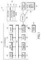
- FIG. 1 illustrates a network environment including an electronic device according to various embodiments of the present invention.
- the electronic device 101 may include at least one of a bus 110, a processor 120, a memory 130, an I/O interface 150, a display module 160, a communication interface 170, a sensor unit 175, a camera system 180, and a camera control module 190. According to various embodiments of the present invention, the electronic device 101 may omit at least one of the foregoing elements or may further include other elements.
- the bus 110 may include a circuit for interconnecting the elements 120 through 190 described above and for allowing communication (e.g., a control message and/or data) between the elements 120 through 190.
- the processor 120 may include one or more of a CPU, an AP, and a communication processor (CP).
- the processor 120 performs operations or data processing for control and/or communication of, for example, at least one other elements of the electronic device 101.
- the processor 120 may be referred to as a controller, may include the controller as a part thereof, or may form the controller.
- the memory 130 may include a volatile memory and/or a non-volatile memory.
- the memory 130 may store, for example, commands or data associated with at least one other elements of the electronic device 101.
- the memory 130 may store software and/or a program 140.
- the program 140 may include, for example, a kernel 141, middleware 143, an application programming interface (API) 145, and/or an application program (or an application) 147.
- At least some of the kernel 141, the middleware 143, and the API 145 may be referred to as an operating system (OS).
- OS operating system
- the kernel 141 controls or manages, for example, system resources (e.g., the bus 110, the processor 120, or the memory 130) used to execute an operation or a function implemented in other programs (e.g., the middleware 143, the API 145, or the application program 147).
- system resources e.g., the bus 110, the processor 120, or the memory 130
- the kernel 141 provides an interface through which the middleware 143, the API 145, or the application program 147 accesses separate components of the electronic device 101 to control or manage the system resources.
- the middleware 143 may work as an intermediary for allowing, for example, the API 145 or the application program 147 to exchange data in communication with the kernel 141.
- the middleware 143 may perform control (e.g., scheduling or load balancing) with respect to the task requests, for example, by giving priorities for using a system resource (e.g., the bus 110, the processor 120, or the memory 130) of the electronic device 101 to at least one of the application programs 147.
- control e.g., scheduling or load balancing
- the API 145 is an interface used for the application 147 to control a function provided by the kernel 141 or the middleware 143, and may include, for example, at least one interface or function (e.g., a command) for file control, window control, image processing or character control.
- a command e.g., a command for file control, window control, image processing or character control.
- the I/O interface 150 serves as an interface for delivering a command or data input from a user or another external device to other element(s) of the electronic device 101.
- the I/O interface 150 may also output a command or data received from other element(s) of the electronic device 101 to a user or another external device.
- the display module 160 may include, for example, a liquid crystal display (LCD), a light emitting diode (LED) display, an organic light emitting diode (OLED) display, a MicroElectroMechanical System (MEMS) display, or an electronic paper display.
- the display module 160 may display various contents (e.g., a text, an image, video, an icon, or a symbol) to users.
- the display module 160 may include a touch screen, and receives a touch, a gesture, proximity, or a hovering input, for example, by using an electronic pen or a part of a body of a user.
- the communication interface 170 sets up communication, for example, between the electronic device 101 and an external device (e.g., a first external electronic device 102, a second external electronic device 104, or a server 106).
- the communication interface 170 may directly communicate with the external device (e.g., the second external electronic device 104 or the server 106) via a wire or wirelessly.
- the communication interface 170 is connected to a network 162 through wireless or wired communication to communicate with the external device (e.g., the second external electronic device 104 or the server 106).
- the communication interface 170 may include a CP which may form one of a plurality of modules of the communication interface 170. In an embodiment of the present invention, the CP may be included in the processor 120.
- the wireless communication may use, as a cellular communication protocol, for example, at least one of long term evolution (LTE), LTE-advanced (LTE-A), code division multiple access (CDMA), wideband CDMA (WCDMA), a universal mobile telecommunication system (UMTS), wireless broadband (WiBro), or global system for mobile communications (GSM).
- LTE long term evolution
- LTE-A LTE-advanced
- CDMA code division multiple access
- WCDMA wideband CDMA
- UMTS universal mobile telecommunication system
- WiBro wireless broadband
- GSM global system for mobile communications
- the wired communication may include, for example, at least one of a universal serial bus (USB), a high definition multimedia interface (HDMI), a recommended standard (RS)-232, and a plain old telephone service (POTS).
- USB universal serial bus
- HDMI high definition multimedia interface
- RS recommended standard
- POTS plain old telephone service
- the network 162 may include a telecommunications network, for example, at least one of a computer network (e.g., a local area network (LAN) or a wide area network (WAN)), Internet, a telephone network, an IP multimedia core network subsystem (IMS), a packet data network (PDN), and a 3 rd Generation Partnership Project (3GPP)/ 3 rd Generation Partnership Project 2 (3GPP2) circuit switched (CS) network.
- a computer network e.g., a local area network (LAN) or a wide area network (WAN)
- IMS IP multimedia core network subsystem
- PDN packet data network
- 3GPP 3 rd Generation Partnership Project
- 3GPP2 3 rd Generation Partnership Project 2
- CS circuit switched
- Each of the first external electronic device 102 and the second external electronic device 104 may be a device of the same type as or a different type than the electronic device 101.
- the server 106 may include a group of one or more servers. According to various embodiments of the present invention, all or some of operations performed in the electronic device 101 may be performed in another electronic device or a plurality of electronic devices (e.g., the external electronic devices 102 and 104 or the server 106).
- the electronic device 101 may request another device (e.g., the external electronic devices 102 and 104 or the server 106) to perform at least some functions associated with the function or the service instead of or in addition to executing the function or the service.
- the other electronic device e.g., the external electronic devices 102 and 104 or the server 106
- the electronic device 101 provides the received result or provides the requested function or service by processing the received result.
- cloud computing, distributed computing, or client-server computing may be used.
- the sensor unit 175 may include at least one sensors for detecting a state or a surrounding environment state of the electronic device 101.
- the sensor unit 175 may include at least one of a proximity sensor for detecting a user's proximity to the electronic device 101 of a user, a motion/orientation sensor for detecting a motion (e.g., rotation, acceleration, deceleration, and/or vibration) of the electronic device 101, and an illumination sensor for detecting ambient illumination.
- the motion/orientation sensor may include at least one of an acceleration sensor, a gravity sensor, a geomagnetic sensor, a gyro sensor, a shock sensor, a global positioning system (GPS) module, and a compass sensor.
- GPS global positioning system
- the sensor unit 175 detects a state of the electronic device 101 and transmits a signal indicating the state of the electronic device 101 to the processor 120.
- the GPS module may receive electric waves from a plurality of GPS satellites (not illustrated) around the Earth's orbit and calculate the position of the electronic device 101 by using a time of arrival of the electric waves from the GPS satellite (not illustrated) to the electronic device 101.
- the compass sensor calculates a posture or orientation of the electronic device 101.
- the camera system 180 photographs a subject and outputs an image of the photographed subject.
- the display 160 displays an image input from the camera system 180.
- the camera system 180 may include a camera module for outputting the image of the subject.
- the camera system 180 may include a camera module for outputting the image of the subject and an image processing device for processing the image output from the camera module.
- the image processing device may include a first image signal processor (ISP) for performing first processing with respect to the image output from the camera module and a second ISP for performing second processing with respect to the image output from the camera module or performing the first processing in association with the first ISP.
- ISP image signal processor
- the camera control module 190 performs at least one of operations implemented in the electronic device 101 to support driving of the electronic device 101.
- the server 106 may include a camera control server module 108 capable of supporting the camera control module 190 implemented in the electronic device 101.
- the camera control server module 108 may include at least one element of the camera control module 190 to perform at least one of operations implemented by the camera control module 190.
- the camera control module 190 processes at least a part of information obtained from other elements (for example, at least one of the processor 120, the memory 130, the I/O interface 150, the display module 160, the communication interface 170, and/or the like), and uses the processed information part in various ways.
- the camera control module 190 may control at least some functions of the electronic device 101 by using or independently of the processor 120, so that the electronic device 101 interworks with another electronic device (e.g., the external electronic device 102 or 104 or the server 106).
- the camera control module may be integrated into the processor 120.
- At least an element of the camera control module 190 may be included in the server 106 (e.g., the camera control server module 108), and at least one operations implemented in the camera control module 190 may be supported by the server 106.
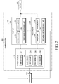
- FIG. 2 illustrates a camera system according to various embodiments of the present invention.
- the camera system 180 may include at least one of a camera module 210 and an image processing device 202.
- the camera module 210 photographs a subject, outputs an image of the photographed subject, and may include a lens system 211 and an image sensor 212.
- the lens system 211 may form an image of the subject by converging light input from outside.
- the lens system 211 may include at least one lens, which may be convex or aspheric.
- the lens system 211 is symmetrical with respect to an optical axis that passes through a centre thereof, and the optical axis is defined as a central axis.
- the image sensor 212 detects an optical image formed by the lens system 211 as an electric image signal.
- the image sensor 212 may include a first input/output (I/O) unit 214 (or a first I/O circuit), a first memory 216, and a sensing unit 218 (or a sensing circuit).
- the image sensor 212 may be a charge-coupled device (CCD) image sensor, a complementary metal-oxide semiconductor (CMOS) image sensor, and/or the like.
- CCD charge-coupled device
- CMOS complementary metal-oxide semiconductor
- the first I/O unit 214 may function as an interface for input and/or output of a signal/data with an external device (e.g., the processor 120, the image processing device 202, and/or the like).
- the first I/O unit 214 delivers a signal/data input from the external device to the first memory 216 or the sensing unit 218.
- the first I/O unit 214 delivers a signal/data input from the first memory 216 or the sensing unit 218 to the external device.
- the first memory 216 stores at least one of a program (e.g., firmware) for operating the camera module 210, configuration information (e.g., a plurality of setting values) of the camera module 210, and an image detected by the sensing unit 218.
- a program e.g., firmware
- configuration information e.g., a plurality of setting values
- the sensing unit 218 detects an optical image formed by the lens system 211 as a digital image.
- the sensing unit 218 may include a plurality of pixel units arranged in an M ⁇ N matrix, and each pixel unit includes a photodiode and a plurality of transistors.
- the pixel unit accumulates an electric charge generated by input light, and a voltage based on the accumulated electric charge indicates an illuminance of the incident light.
- image data output from the image sensor includes a set of voltages (i.e., pixel values) output from the pixel units, and the image data indicates one image (i.e., a still image) that includes M ⁇ N pixels.
- the sensing unit 218 may operate all pixels thereof or only pixels of a region of interest (ROI) according to a setting value received from the processor 120. For example, the sensing unit 218 may operate according to a control signal input from the processor 120 or the image processing device 202.
- ROI region of interest
- the camera module 210 may further include a driving unit for moving the lens system 211 along an optical axis for focus control.
- the driving unit may operate according to a control signal input from the sensing unit 218, the processor 120, or the image processing device 202.
- the sensing unit 218 may include a controller for controlling overall operations of the camera module 210 and/or the image sensor 212.
- the image processing device 202 may process an image output from the camera module.
- the image processing device 202 may include a first ISP 220 and a second ISP 230.
- the first ISP 220 performs first processing with respect to the image output from the camera module 210.
- the first ISP 220 may include a second I/O unit 224 (or a second I/O circuit), a second memory 226, and a first image processing unit 228 (or a first image processing circuit).
- the second I/O unit 224 functions as an interface for input and/or output of a signal/data with an external device (e.g., the processor 120, the camera module 210, the display 160, and the second ISP 230).
- the second I/O unit 224 delivers the signal/data input from the external device to the second memory 226 or the first image processing unit 228.
- the second I/O unit 224 delivers the signal/data input from the second memory 226 or the first image processing unit 228 to the external device.
- the second memory 226 stores at least one of a program (e.g., firmware) for operating the first ISP 220, configuration information (e.g., a plurality of setting values) of the first ISP 220, an image processed or to be processed by the first ISP 220 and/or the second ISP 230, and image processing information processed by the first ISP 220 and/or the second ISP 230.
- a program e.g., firmware
- configuration information e.g., a plurality of setting values
- the first image processing unit 228 performs first processing with respect to the image output from the camera module 210.
- the first image processing unit 228 processes the image input from the camera module 210 frame-by-frame under control of the processor 120.
- the first image processing unit 228 outputs an image converted to fit for screen characteristics (e.g., size, quality, and/or resolution) of the display 160.
- the first image processing unit 228 may perform at least one processing of automatic exposure (AE), auto white balance (AWB), autofocus (AF), noise reduction, resizing/scaling, colour space conversion (CSC), and gamma correction with respect to an image input from the camera module 210.
- AE automatic exposure
- AVB auto white balance
- AF autofocus
- CSC colour space conversion
- the second ISP 230 performs second processing with respect to the image output from the camera module 210 independently of the first ISP 220 or performs the first processing or the second processing in association with the first ISP 220.
- the second ISP 230 may include a third I/O unit 234 (or a third I/O circuit), a third memory 236, and a second image processing unit 238 (or a second image processing circuit).
- the third I/O unit 234 functions as an interface for input and/or output of a signal/data with an external device (e.g., the processor 120, the camera module 210, the display 160, or the first ISP 220).
- the third I/O unit 234 delivers the signal/data input from the external device to the third memory 236 or the second image processing unit 238.
- the third I/O unit 234 delivers the signal/data input from the third memory 236 or the second image processing unit 238 to the external device.
- the third memory 236 stores at least one of a program (e.g., firmware) for operating the second ISP 230, configuration information (e.g., a plurality of setting values) of the second ISP 230, an image processed or to be processed by the second ISP 230, and image processing information processed by the second ISP 230.
- a program e.g., firmware
- configuration information e.g., a plurality of setting values
- the second image processing unit 238 performs second processing with respect to the image output from the camera module 210 independently of the first ISP 220 or performs the first processing or the second processing in association with the first ISP 220.
- the second image processing unit 238 processes the image input from the camera module 210 and/or the first ISP 220 frame-by-frame under control of the processor 120 and/or the first ISP 220.
- the second image processing unit 238 outputs an image converted to fit for screen characteristics (e.g., size, quality, and/or resolution) of the display 160.
- the second image processing unit 238 may perform at least one processing of AE, AWB, AF, noise reduction, resizing/scaling, CSC, and gamma correction with respect to an image input from the camera module 210 and/or the first ISP 220.
- the second image processing unit 238 may perform at least one processing of phase detection AF (PAF) (or phase difference detection AF) and high dynamic range imaging (HDRI) for generating an image having a high dynamic range from a plurality of images having different exposure values, in association with the first image processing unit 228.
- PAF phase detection AF
- HDRI high dynamic range imaging
- the second image processing unit 238 may deliver the processed image or information thereof to the first ISP 220.
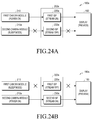
- the image output from the first ISP 220 and the image output from the second ISP 230 may be output to the display 160 sequentially, alternately, or in combination.
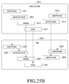
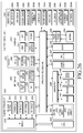
- FIG. 3 is a block diagram of a programming module according to various embodiments of the present invention.
- the programming module 210 e.g., the program 140
- the programming module 210 may include an OS for controlling resources associated with an electronic device (e.g., the electronic device 101) and/or various applications executed on the OS.
- the OS may include Android, iOS, Windows, Symbian, Tizen, or Bada.
- a programming module 310 may include a kernel 320, a middleware 330, an application programming interface (API) 360, and/or an application 370. At least a part of the programming module 310 may be preloaded on an electronic device or may be downloaded from a server (e.g., the server 106).
- a server e.g., the server 106
- the kernel 320 may include a system resource manager 321 and/or a device driver 323.
- the system resource manager 321 may perform control, allocation, or retrieval of system resources.
- the system resource manager 321 may include a process management unit, a memory management unit, or a file system.
- the device driver 323 may include, for example, a display driver, a camera driver, a Bluetooth (BT) driver, a shared memory driver, a USB driver, a keypad driver, a Wi-Fi driver, an audio driver, or an inter-process communication (IPC) driver.
- BT Bluetooth
- IPC inter-process communication
- the middleware 330 may include provide functions that the application 370 commonly requires or provide various functions to the application 370 through the API 360 to allow the application 370 to efficiently use a limited system resource in an electronic device.
- the middleware 330 may include at least one of a runtime library 335, an application manager 341, a window manager 342, a multimedia manager 343, a resource manager 344, a power manager 345, a database manager 346, a package manager 347, a connectivity manager 348, a notification manager 349, a location manager 350, a graphic manager 351, and a security manager 352.
- the runtime library 335 may include a library module that a compiler uses to add a new function through a programming language while the application 370 is executed.
- the runtime library 335 performs functions relating to an I/O, memory management, or calculation operation.
- the application manager 341 manages a life cycle of at least one application among the applications 370.
- the window manager 342 manages a graphical user interface (GUI) resource using a screen.
- the multimedia manager 343 recognizes a format necessary for playing various media files and performs encoding or decoding on a media file by using a codec appropriate for a corresponding format.
- the resource manager 344 manages a resource such as source code, memory, or storage space of at least one application among the applications 370.
- the power manager 345 manages a battery or power in operation with a basic input/output system (BIOS) and provides power information necessary for an operation of the electronic device.
- the database manager 346 performs a management operation to generate, search or change a database used for at least one application among the applications 370.
- the package manager 347 manages the installation or update of an application distributed in a theme package format.
- the theme package may include one file or a plurality of files.
- the connectivity manager 348 manages a wireless connection such as a Wi-Fi or Bluetooth
- the notification manager 349 displays or notifies events such as arrival messages, appointments, and proximity alerts in a manner that is not disruptive to a user.
- the location manager 350 manages location information of an electronic device.
- the graphic manager 351 manages a graphic effect to be provided to a user or a UI related thereto.
- the security manager 352 provides a general security function necessary for system security or user authentication. According to an embodiment of the present invention, when an electronic device (e.g., the electronic device 101) has a call function, the middleware 330 may further include a telephony manager for managing a voice or video call function of the electronic device.
- the middleware 330 may include a middleware module forming a combination of various functions of the above-mentioned internal elements.
- the middleware 330 may provide modules specified according to types of OS so as to provide distinctive functions. Additionally, the middleware 330 may delete some of existing elements or add new elements dynamically.
- the API 360 (e.g., the API 145) may be provided as a set of API programming functions with a different configuration according to the OS.
- one API set may be provided by each platform, and in the case of Tizen, two or more API sets may be provided.
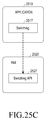
- the application 370 may include one or more applications capable of providing a function, for example, a home application 371, a dialler application 372, a short messaging service/multimedia messaging service (SMS/MMS) application 373, an instant message (IM) application 374, a browser application 375, a camera application 376, an alarm application 377, a contact application 378, a voice dial application 379, an e-mail application 380, a calendar application 381, a media player application 382, an album application 383, a clock application 384, a health care application (e.g., an application for measuring an exercise amount or a blood sugar), or an environment information providing application (e.g., an application for providing air pressure, humidity, or temperature information).
- a health care application e.g., an application for measuring an exercise amount or a blood sugar
- an environment information providing application e.g., an application for providing air pressure, humidity, or temperature information.
- the application 370 may include an application (hereinafter, an "information exchange application" for convenience) supporting information exchange between the electronic device (e.g., the electronic device 101) and an external electronic device (e.g., the external electronic device 102 or 104).
- the information exchange application may include, for example, a notification relay application for transferring specific information to the external electronic device or a device management application for managing the external electronic device.
- the notification relay application may include a function for transferring notification information generated in another application (e.g., an SMS/MMS application, an e-mail application, a health care application, or an environment information application) of the electronic device to an external electronic device (e.g., the external electronic device 102 or 104).
- the notification relay application may receive notification information from an external electronic device to provide the same to a user.
- the device management application may manage (e.g., install, remove, or update) at least one function (e.g., turn on/turn off of an external electronic device 102 or 104 itself (or a part thereof) or control of brightness (or resolution) of a display, a service provided by an application operating in an external electronic device (e.g., the electronic device) or provided by the external electronic device (e.g., a call service or a message service).
- function e.g., turn on/turn off of an external electronic device 102 or 104 itself (or a part thereof) or control of brightness (or resolution) of a display
- a service provided by an application operating in an external electronic device e.g., the electronic device
- the external electronic device e.g., a call service or a message service
- the application 370 may include an application (e.g., a health care application) designated according to an attribute of the external electronic device (e.g., a type of the electronic device being mobile medical equipment as the attribute of the electronic device).
- the application 370 may include an application received from the external electronic device (e.g., the server 106 or the external electronic device 102 or 104).
- the application 370 may include a preloaded application or a third party application that may be downloaded from the server. Names of elements of the programming module 310 according to the illustrated embodiment may vary depending on a type of an OS.
- At least a part of the programming module 310 may be implemented by software, firmware, hardware, or a combination of at least two of them.
- the at least a part of the programming module 310 may be implemented (e.g., executed) by a processor (e.g., the processor 120).
- the at least a part of the programming module 310 may include a module, a program, a routine, sets of instructions, or a process for performing one or more functions.
- FIG. 4 is a block diagram of a camera control module of an electronic device according to various embodiments of the present invention.
- the camera control module 190 may include all of a control module 410 and a display module 420 or at least some thereof.
- the camera control module 190 may be provided separately from a processor (e.g., the processor 120) or may be entirely or partially integrated into the processor.
- the control module 410 performs initialisation necessary for controlling the camera system (e.g., the camera system 180) of the electronic device to operate in a normal mode. Upon completion of the initialisation, the control module 410 controls the camera system to operate in the sleep mode. The control module 410 controls the camera system to switch (or wake up) from the sleep mode to the normal mode.
- the initialisation may be performed if a pre-set first condition is satisfied, and the switch to the normal mode is performed if a pre-set second condition is satisfied.
- the display module 420 controls a display (e.g., the display 160) of the electronic device to display an image output from the camera system in the normal mode.
- the pre-set first condition may include at least one of booting of the electronic device, switching of the electronic device from the sleep mode to the normal mode, turning on of a screen/power of the display (e.g., the display 160) after entrance to the sleep mode of the electronic device, execution of an application including a graphic element (or an item) (e.g., a button, an icon, a menu, a menu item, and/or the like) needing an operation of the camera system, displaying of the screen including the graphic element needing the operation of the camera system, a user's access to the graphic element needing the operation of the camera system, detection of a context associated with the electronic device, which coincides with (or matches) a pre-set context, and detection of at least one word matching at least one pre-set word.
- a graphic element or an item
- the pre-set context with respect to the electronic device may include at least one of when the electronic device is located in or arrives at a pre-set region/place, when a pre-set time is up, when the electronic device operates according to a pre-set operating pattern (e.g., execution of an application (applications)), or when a current state (e.g., a battery state, a wireless signal reception state, a memory state, and/or the like) of the electronic device coincides with (or matches) a pre-set state.
- a pre-set operating pattern e.g., execution of an application (applications)
- a current state e.g., a battery state, a wireless signal reception state, a memory state, and/or the like
- the pre-set context with respect to the electronic device may be determined based on use history information of the electronic device (e.g., a history of the electronic device operating in the sleep mode (or the sleep-mode operation of the electronic device) in a particular place).
- use history information of the electronic device e.g., a history of the electronic device operating in the sleep mode (or the sleep-mode operation of the electronic device) in a particular place.
- the second condition may include at least one of detection of the pre-set context with respect to the electronic device, execution of a camera application, selection of a graphic element needing the operation of the camera system, and reception of a command requesting the operation of the camera system.
- the control module 410 may perform the initialisation. For example, if the electronic device 101 is powered on, the control module 410 may perform device probing for the camera system, a sensor unit (e.g., the sensor unit 175), and the like and loading of an operating system (OS). The control module 410 may perform the initialisation during device probing or booting following the device probing.
- OS operating system
- control module 410 may perform the initialisation if the screen/power of the display is turned off and the electronic device operates in the sleep mode, and then the screen/power of the display is turned on.
- the control module 410 may perform the initialisation if the display module 420 displays the screen including the graphic element needing the operation of the camera system on the display.
- the display module 420 may display the screen including the graphic element needing the operation of the camera system on the display.
- the control module 410 may detect the user's access to the graphic element through the display. Once the user's access to the graphic element through the display is detected, the control module 410 may perform the initialisation.
- the display module 420 may display the screen including the graphic element needing the operation of the camera system on the display.
- the control module 410 may detect a hovering input on the display. If a position of the hovering input is included in a display region of the graphic element, the position of the hovering input is adjacent to the display region of the graphic element, or the hovering input moves toward the graphic element, then the control module 410 may perform the initialisation.
- control module 410 may detect a context associated with the electronic device.
- the control module 410 may search for information associated with the context in a database stored in a memory (e.g., the memory 130) of the electronic device. Once the information associated with the context is found in the database, the control module 410 may perform the initialisation.
- control module 410 may receive a user's voice (e.g., a voice input through a microphone) or text through an I/O interface (e.g., the I/O interface 150) or the display (e.g., the display 160) of the electronic device. If at least one word matching at least one pre-set word is detected in the voice or text, the control module 410 may perform the initialisation.
- a user's voice e.g., a voice input through a microphone
- I/O interface e.g., the I/O interface 150
- display e.g., the display 160
- the control module 410 may receive a voice (e.g., a voice of the other party during a voice communication) or a text (e.g., a text message) from an external device through a communication interface (e.g., the communication interface 170), an I/O interface (e.g., the I/O interface 150), and a display (e.g., the display 160) of the electronic device.
- a voice e.g., a voice of the other party during a voice communication
- a text e.g., a text message
- a communication interface e.g., the communication interface 170
- I/O interface e.g., the I/O interface 150
- a display e.g., the display 160
- the camera system may include at least one of the camera module (e.g., the camera module 210) that outputs an image of a subject and an image processing device (e.g., the image processing device 202) that performs processing with respect to the image output from the camera module.
- the camera module e.g., the camera module 210
- an image processing device e.g., the image processing device 202
- the image processing device may include at least one of a first ISP (e.g., the first ISP 220) that performs first processing with respect to the image output from the camera module and a second ISP (e.g., the second ISP 230) that performs second processing with respect to the image output from the camera module independently of the first ISP or that performs the first processing or the second processing in association with the first ISP.
- a first ISP e.g., the first ISP 220
- a second ISP e.g., the second ISP 230
- the control module 410 may apply power to at least a part of the camera system.
- the control module 410 delivers at least one of a program for operating at least a part of the camera system or configuration information of the camera system to at least a part of the camera system.
- the at least a part of the camera system may undergo a state change from an inoperable state to an operable state after execution of the program.
- the control module 410 may store a program (e.g., firmware) for operating at least a part of the camera system in an internal memory (or internal memories) (e.g., the first memory 216, the second memory 226, and/or the third memory 236) of the camera system.
- the control module 410 delivers setting values of the at least a part of the camera system to the at least a part of the camera system or stores the setting values in an internal memory (internal memories) of the camera system.
- the program may be configured to apply the setting values to the at least a part of the camera system or to perform generation or correction of an image/image-associated data based on the setting values.
- the configuration information or the setting values of the camera system may include at least one of an international standardization organization (ISO) setting value, a white balance (WB)/AWB setting value, a frame rate, a capture resolution, a preview resolution, a preview format setting value, an AE setting value, an AF setting value, a noise reduction setting value, a resizing/scaling setting value, a CSC setting value, a gamma correction setting value, a PAF setting value, an HDRI setting value, and allocation information of a region of a memory for the image processing device to process the image input from the camera module.
- ISO international standardization organization
- WB/AWB setting value white balance
- a frame rate a capture resolution
- a preview resolution a preview format setting value
- AE setting value an AF setting value
- noise reduction setting value a noise reduction setting value
- a resizing/scaling setting value a CSC setting value
- gamma correction setting value a PAF setting value
- the control module 410 may store a program for operating at least a part of the camera system in an internal memory (internal memories) of the camera system.
- the control module 410 delivers a message including a plurality of setting values of the at least a part of the camera system to the at least a part of the camera system or stores the message in the internal memory (internal memories) of the camera system.
- the control module 410 may deliver a message (or a data frame) including a plurality of setting values (or all setting values) for a camera module to the camera module or store the message (or the data frame) in an internal memory of the camera module.
- control module 410 may deliver a message (or a data frame) including a plurality of setting values (or all setting values) for an image processing device to the image processing device or store the message (or the data frame) in an internal memory of the image processing device.
- control module 410 may deliver a message (or a data frame) including a plurality of setting values (or all setting values) for a first ISP and/or a second ISP to the first ISP or store the message (or the data frame) in an internal memory of the first ISP.
- control module 410 may deliver a message (or a data frame) including a plurality of setting values (or all setting values) for the second ISP to the second ISP or store the message (or the data frame) in an internal memory of the second ISP.
- the control module 410 may store a program for operating at least a part of the camera system in an internal memory (internal memories) of the camera system.
- the at least a part of the camera system obtains setting values stored in an internal memory (internal memories) of the at least a part of the camera system.
- the program for operating the at least a part of the camera system may be configured to automatically obtain the setting values stored in a pre-set region of the internal memory.
- the control module 410 may deliver at least one of a program for operating the camera module and configuration information of the camera module to the camera module or stores the at least one of the program and the configuration information in an internal memory of the camera module.
- the control module 410 delivers at least one of a program for operating the at least a part of the image processing device and configuration information of the at least a part of the image processing device to the at least a part of the image processing device or stores the at least one of the program and the configuration information in an internal memory of the image processing device.
- the control module 410 may deliver at least one of a program for operating the camera module and configuration information of the camera module to the camera module or stores the at least one of the program and the configuration information in an internal memory of the camera module.
- the control module 410 delivers at least one of a program for operating the first ISP and configuration information of the first ISP to the first ISP or stores the at least one of the program and the configuration information in an internal memory of the first ISP.
- the control module 410 delivers at least one of a program for operating the second ISP and configuration information of the second ISP to the second ISP or stores the at least one of the program and the configuration information in an internal memory of the second ISP.
- the control module 410 may store the program for operating the camera module in an internal memory of the camera module.
- the control module 410 delivers setting values of the camera module to the camera module or stores the setting values in the internal memory of the camera module.
- the control module 410 stores a program for operating at least a part of the image processing device in an internal memory of the at least a part of the image processing device.
- the control module 410 delivers setting values of the at least a part of the image processing device to the at least a part of the image processing device or stores the setting values in the internal memory of the image processing device.
- control module 410 may control the camera module to photograph a subject.
- the control module 410 controls the image processing device to process an image of the subject output from the camera module.
- the display module 420 controls the display to display the processed image.
- control module 410 may automatically perform the initialisation and a sleep-mode operation of the camera system.
- the control module 410 may provide, to the camera system, second power lower than first power provided to the camera system in the normal mode.
- the second power may include minimum power for maintaining data stored in the internal memory of the camera system and minimum power for signal input from an external device.
- no power or minimum power may be supplied to a sensing unit (e.g., the sensing unit 218) and/or an image processing unit (e.g., the first image processing unit 228 or the second image processing unit 238).
- the camera system may be in a state capable of capturing or processing an image in the normal mode and may be in a state incapable of at least one of capturing an image and processing the image in the sleep mode.
- control module 410 may apply the first power to the camera system.
- control module 410 may synchronize switching of at least one elements of the camera system between the normal mode and the sleep mode with switching of at least one elements of the electronic device between screen/power-on and screen/power-off. For example, when at least one elements of the electronic device are in a screen/power-on state, the control module 410 may control the at least one elements of the camera system to operate in the normal mode. When the at least one elements of the electronic device are in a screen/power-off state, the control module 410 controls the at least one elements of the camera system to operate in the sleep mode.
- control module 410 may synchronize switching of the camera module of the camera system between the normal mode and the sleep mode with switching of the display of the electronic device between screen/power-on and screen/power-off.
- control module 410 may synchronize switching of at least one elements of the camera system between the normal mode and the sleep mode with switching between execution and termination of at least one applications of the electronic device. For example, when the at least one applications of the electronic device are being executed, the control module 410 controls the at least one elements of the camera system to operate in the normal mode. Once the at least one applications of the electronic device are terminated, the control module 410 controls the at least one elements of the camera system to operate in the sleep mode.
- control module 410 may synchronize switching of a second ISP between the normal mode and the sleep mode with switching between execution and termination of a camera application of the electronic device.
- control module 410 may synchronize switching of at least one elements of the camera system between the normal mode and the sleep mode with switching of at least one elements of the electronic device between the normal mode and the sleep mode. For example, when the at least one elements of the electronic device operate in the normal mode, the control module 410 may control the at least one elements of the camera system to operate in the normal mode. When the at least one elements of the electronic device operate in the sleep mode, the control module 410 may control the at least one elements of the camera system to operate in the sleep mode.
- control module 410 may synchronize switching of the first ISP between the normal mode and the sleep mode with switching of the processor between the normal mode and the sleep mode.
- control module 410 may perform initialisation of the camera system. Upon completion of the initialisation, the control module 410 controls at least one of a first camera module and a second camera module of the camera system to operate in the normal mode.
- the display module 420 controls the display to display an image output from the at least one of the first camera module and the second camera module.
- control module 410 may control the first camera module and the second camera module to simultaneously operate in the normal mode.
- control module 410 may perform initialisation of the camera system if the pre-set first condition is satisfied.
- control module 410 may control the camera system to operate in the sleep mode.
- the control module 410 switches the camera system from the sleep mode to the normal mode.
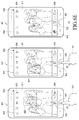
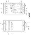
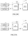
- the camera system may include the first camera module for outputting a first image of a first subject situated in front of the electronic device, the second camera module for outputting a second image of a second subject situated at the rear of a second subject, and an image processing device for processing the first image and/or the second image.
- the image processing device may include a first ISP for performing first processing with respect to the first image and a second ISP for performing second processing with respect to the second image.
- the control module 410 may control the first camera module and the second camera module to simultaneously operate in the normal mode.
- the control module 410 performs first processing with respect to the first image output from the first camera module.
- the control module 410 performs second processing with respect to the second image output from the second camera module.
- the display module 420 controls the display to display the first image processed by the first processing or the second image processed by the second processing.
- the display module 420 may control the display to stop displaying an image output from one of the first camera module and the second camera module and to display an image output from the other of the first camera module and the second camera module.
- control module 410 may control the one of the first camera module and the second camera module to operate in the normal mode and the other of the first camera module and the second camera module to operate in the sleep mode.
- control module 410 may control one of the first ISP and the second ISP, which corresponds to the one of the first camera module and the second camera module, to operate in the normal mode and controls the other of the first ISP and the second ISP, which corresponds to the other of the first camera module and the second camera module, to operate in the sleep mode.
- the display module 420 controls the display to output an image output from the one of the first ISP and the second ISP (i.e., an ISP operating in the normal mode).
- control module 410 may control the other of the first camera module and the second camera module to operate in the sleep mode.
- control module 410 controls the one of the first camera module and the second camera module to operate in the sleep mode.
- the control module 410 switches the other of the first camera module and the second camera module from the sleep mode to the normal mode.
- the display module 420 controls the display to display an image output from the other of the first camera module and the second camera module.
- control module 410 controls the one of the first camera module and the second camera module to operate in the sleep mode and at the same time, switches the other of the first camera module and the second camera module from the sleep mode to the normal mode.
- API application programming interface
- FIG. 5 is a flowchart of a method for operating an electronic device according to various embodiments of the present invention.
- a method for operating the electronic device may include operations 510 through 540.
- the method for operating the electronic device may be performed by an electronic device (e.g., the electronic device 101), a processor (e.g., the processor 120) of the electronic device, or a camera control module (e.g., the camera control module 190) of the electronic device.
- an electronic device e.g., the electronic device 101
- a processor e.g., the processor 120
- a camera control module e.g., the camera control module 190
- the electronic device performs initialisation necessary for controlling a camera system (e.g., the camera system 180) to operate in the normal mode.
- the electronic device may perform the initialisation if a pre-set first condition is satisfied.
- the pre-set first condition may include at least one of booting of the electronic device, switching of the electronic device from the sleep mode to the normal mode, turning on of a screen/power of the display (e.g., the display 160) after entrance to the sleep mode of the electronic device, execution of an application including a graphic element (or an item, (e.g., a button, an icon, a menu, a menu item, and/or the like)) needing an operation of the camera system, displaying of the screen including the graphic element needing the operation of the camera system, a user's access to the graphic element needing the operation of the camera system, detection of a context associated with the electronic device, which coincides with (or matches) a pre-set context, and detection of at least one word matching at least one pre-set word.
- a graphic element or an item, (e.g., a button, an icon, a menu, a menu item, and/or the like)
- the pre-set context with respect to the electronic device may include at least one of when the electronic device is located in or arrives at a pre-set region/place, when a pre-set time is up, when the electronic device operates according to a pre-set operating pattern (e.g., execution of an application (or applications)), or when a current state (e.g., a battery state, a wireless signal reception state, a memory state, and/or the like) of the electronic device coincides with (or matches) a pre-set state.
- a pre-set operating pattern e.g., execution of an application (or applications)
- a current state e.g., a battery state, a wireless signal reception state, a memory state, and/or the like
- the pre-set context with respect to the electronic device may be determined based on use history information of the electronic device (e.g., a history of a sleep-mode operation of the electronic device in a particular place).
- the camera system may include at least one of a camera module (e.g., the camera module 210) for outputting an image of a subject and an image processing device (e.g., the image processing device 202) for processing the image output from the camera module.
- a camera module e.g., the camera module 210
- an image processing device e.g., the image processing device 202
- the image processing device may include at least one of a first ISP (e.g., the first ISP 220) that performs first processing with respect to the image output from the camera module and a second ISP (e.g., the second ISP 230) that performs second processing with respect to the image output from the camera module independently of the first ISP or that performs the first processing or the second processing in association with the first ISP.
- a first ISP e.g., the first ISP 220
- a second ISP e.g., the second ISP 230
- the electronic device may apply power to at least a part of the camera system.
- the electronic device delivers at least one of a program for operating at least the part of the camera system or configuration information of the camera system to at least the part of the camera system.
- the at least a part of the camera system may undergo a state change from an inoperable state to an operable state after execution of the program.
- the electronic device may store a program (e.g., firmware) for operating at least the part of the camera system in an internal memory (or internal memories) (e.g., the first memory 216, the second memory 226, and/or the third memory 236) of the camera system.
- the electronic device delivers setting values of the at least the part of the camera system to the at least the part of the camera system or stores the setting values in an internal memory (internal memories) of the camera system.
- the program may be configured to apply the setting values to the at least the part of the camera system or to perform generation or correction of an image/image-associated data based on the setting values.
- the configuration information or the setting values of the camera system may include at least one of an ISO setting value, a WB/AWB setting value, a frame rate, a capture resolution, a preview resolution, a preview format setting value, an AE setting value, an AF setting value, a noise reduction setting value, a resizing/scaling setting value, a CSC setting value, a gamma correction setting value, a PAF setting value, an HDRI setting value, and allocation information of a region of a memory for the image processing device to process the image input from the camera module.
- the electronic device may store a program for operating at least the part of the camera system in an internal memory (internal memories) of the camera system.
- the electronic device delivers a message including a plurality of setting values of the at least the part of the camera system to the at least the part of the camera system or stores the message in the internal memory (internal memories) of the camera system.
- the electronic device may deliver a message (or a data frame) including a plurality of setting values (or all setting values) for a camera module to the camera module or store the message (or the data frame) in an internal memory of the camera module.
- the electronic device may deliver a message (or a data frame) including a plurality of setting values (or all setting values) for an image processing device to the image processing device or store the message (or the data frame) in an internal memory of the image processing device.
- the electronic device may deliver a message (or a data frame) including a plurality of setting values (or all setting values) for a first ISP and/or a second ISP to the first ISP or store the message (or the data frame) in an internal memory of the first ISP.
- the electronic device may deliver a message (or a data frame) including a plurality of setting values (or all setting values) for the second ISP to the second ISP or store the message (or the data frame) in an internal memory of the second ISP.
- the at least the part of the camera system obtains setting values stored in an internal memory (internal memories) of the at least the part of the camera system.
- the program for operating the at least the part of the camera system may be configured to automatically obtain the setting values stored in a pre-set region of the internal memory.
- the electronic device may deliver at least one of a program for operating the camera module and configuration information of the camera module to the camera module or stores the at least one of the program and the configuration information in an internal memory of the camera module.
- the electronic device delivers at least one of a program for operating the at least a part of the image processing device and configuration information of the at least a part of the image processing device to the at least a part of the image processing device or stores the at least one of the program and the configuration information in an internal memory of the image processing device.
- the electronic device may deliver at least one of the program for operating the camera module and configuration information of the camera module to the camera module or stores the at least one of the program and the configuration information in an internal memory of the camera module.
- the electronic device delivers at least one of a program for operating the first ISP and configuration information of the first ISP to the first ISP or stores the at least one of the program and the configuration information in an internal memory of the first ISP.
- the electronic device delivers at least one of a program for operating the second ISP and configuration information of the second ISP to the second ISP or stores the at least one of the program and the configuration information in an internal memory of the second ISP.
- the electronic device may store the program for operating the camera module in an internal memory of the camera module.
- the electronic device delivers setting values of the camera module to the camera module or stores the setting values in the internal memory of the camera module.
- the electronic device stores a program for operating at least a part of the image processing device in an internal memory of the at least a part of the image processing device.
- the electronic device delivers setting values of the at least a part of the image processing device to the at least a part of the image processing device or stores the setting values in the internal memory of the image processing device.
- the electronic device controls the camera system to operate in the sleep mode.
- the electronic device may automatically perform the initialisation and the sleep-mode operation of the camera system.
- the electronic device may provide, to the camera system, second power lower than first power provided to the camera system in the normal mode.
- the second power may include minimum power for maintaining data stored in the internal memory of the camera system and minimum power for signal input from an external device.
- no power or minimum power may be supplied to a sensing unit (e.g., the sensing unit 218) and/or an image processing unit (e.g., the first image processing unit 228 or the second image processing unit 238).
- the camera system may be in a state capable of capturing or processing an image in the normal mode and may be in a state incapable of at least one of capturing an image and processing the image in the sleep mode.
- the electronic device controls the camera system to switch (or wake up) from the sleep mode to the normal mode.
- switching to the normal mode may be performed if a pre-set second condition is satisfied.
- the second condition may include at least one of detection of a pre-set context with respect to the electronic device, execution of a camera application, selection of a graphic element needing the operation of the camera system, and reception of a command requesting the operation of the camera system.
- the electronic device to control the camera system to switch from the sleep mode to the normal mode, the electronic device provides the first power to the camera system.
- the electronic device controls the display of the electronic device to display an image output from the camera system in the normal mode.
- the image output from the camera system may be a live preview image.
- FIGS. 6A to 6H are diagrams for describing a method for operating an electronic device according to various embodiments of the present invention.
- a memory e.g., the memory 130 of an electronic device 601 (e.g., the electronic device 101) stores a camera application, a voice recognition application, and/or the like.
- the electronic device 601 displays a screen 610 (e.g., a home screen) including executable icons mapped to applications such as a camera application, a voice recognition application, and/or the like, on a display 606 (e.g., the display 160).
- the electronic device 601 detects an input of a user 611 for selecting a camera icon 612. Prior to the input, the electronic device 601 performs initialisation necessary for controlling the camera system (e.g., the camera system 180) to operate in the normal mode. Upon completion of the initialisation, the electronic device 601 controls the camera system to operate in the sleep mode. The electronic device 601 controls the camera system to switch to the normal mode from the sleep mode in response to the input. The electronic device 601 executes a camera application in response to the input.
- initialisation necessary for controlling the camera system (e.g., the camera system 180) to operate in the normal mode.
- the electronic device 601 controls the camera system to operate in the sleep mode.
- the electronic device 601 controls the camera system to switch to the normal mode from the sleep mode in response to the input.
- the electronic device 601 executes a camera application in response to the input.
- the electronic device 601 may detect an input needing execution of the camera application through an I/O interface (e.g., the I/O interface 150), a communication interface (e.g., the communication interface 170), or a sensor unit (e.g., the sensor unit 175).
- the input may be one of information in various forms input to the electronic device 601, such as a gesture, a voice, and a biometric signal of the user 611, and so forth.
- a camera application screen 620 (or a camera application window) is displayed on a display 606 of the electronic device 601.
- a first menu bar 630 including an environment setting menu
- a second menu bar 650 including a shutter button 652
- a live preview image 640 may include a figure of a subject, e.g., a child.
- the electronic device 601 controls the camera system to output the live preview image 640 (e.g., a real-time video) having a lower resolution (or a smaller number of pixels) and/or a smaller size.
- the live preview image 640 may be temporarily stored in the memory so as to be displayed on the display 606 and then may be automatically deleted, without being permanently stored in the memory.
- the electronic device 601 may detect selection of the shutter button 652 (or an input of a shooting command) from the user 611.
- the electronic device 601 controls the camera system to output an image (e.g., a still image, a video, and/or the like) having a higher resolution (or a greater number of pixels) and/or a larger size in response to selection of the shooting button 652.
- the electronic device 601 may store the image having the higher resolution and/or the larger size (or an image captured according to a user input) in the memory and display the image on the display 606.
- the image captured according to the user input may be permanently stored in the memory and then may be deleted according to a subsequent user input.
- the electronic device 601 displays the screen 610 (e.g., a home screen) including executable icons mapped to applications such as the camera application, the voice recognition application, and so forth on the display 606 (e.g., the display 160).
- the screen 610 e.g., a home screen
- applications such as the camera application, the voice recognition application, and so forth on the display 606 (e.g., the display 160).
- the electronic device 601 may detect a user's selection of a button or a key included in an I/O interface (e.g., the I/O interface 150) when the display 606 is in a power/screen-off state or the electronic device 601 enters the sleep mode (including the power/screen-off state of the display 606).
- an I/O interface e.g., the I/O interface 150
- the electronic device 601 may detect a user's selection of a button or a key included in an I/O interface (e.g., the I/O interface 150) while displaying a screen such as an application screen, a lock screen, a home screen, and/or the like.
- a button may be formed on a front surface, a side surface, or a rear surface of the electronic device 601 and may include at least one of a power button, a volume button (e.g., a volume-up button and a volume-down button), a menu button, a home button/key 602, a back button, and a search button.
- the electronic device 601 may detect an input (e.g., a double click, a long click/press, and/or the like) of the user 611 for selecting the home button (or the home key) 602. Prior to the input, the electronic device 601 may perform initialisation necessary for controlling the camera system (e.g., the camera system 180) to operate in the normal mode. Upon completion of the initialisation, the electronic device 601 controls the camera system to operate in the sleep mode. In response to the input, the electronic device 601 controls the camera system to switch from the sleep mode to the normal mode. The electronic device 601 executes a camera application (or an application associated with the camera system) in response to the input.
- a camera application or an application associated with the camera system
- the input of the user 611 may include at least one of a click which is a gesture of shortly or gently pressing or tapping a button, a double click which is a gesture of quickly pressing or tapping a button twice, a long press which is a gesture of pressing a button long, and a short press which is a gesture of pressing a button shortly.
- a click which is a gesture of shortly or gently pressing or tapping a button
- a double click which is a gesture of quickly pressing or tapping a button twice
- a long press which is a gesture of pressing a button long
- a short press which is a gesture of pressing a button shortly.
- the input of the user 611 may include at least one of a touch, a long touch, a tap, a double tap, a click, a double click, a flick, a drag (or touch & move), a drag & drop, a swipe, multi-swipes, pinches, a shake, and rotation.
- the touch is a gesture of putting a user's input unit (e.g., a finger, a pen, and/or the like) on the display 606 (or a button)
- the long touch or touch & hold
- the tap is a gesture of shortly and gently tapping the display 606 (or a button)
- the double tap is a gesture of quickly tapping the display 606 (or a button) twice
- the flick is a gesture (e.g., a scroll) of quickly moving the user's input unit on the display 606 and removing the user's input unit from the display 606
- the drag is a gesture of moving or scrolling a graphic element (or an item) (e.g., a button, an icon, a menu, a menu item, and/or the like) displayed on the display 606
- the drag & drop is a gesture of moving a graphic element while touching the display 606, and then stopping moving the graphic element to remove the user's input unit
- the camera application screen 620 (or a camera application window) is displayed on the display 606 of the electronic device 601.
- the first menu bar 630 including the environment setting menu
- the second menu bar 650 including the shutter button 652
- the live preview image 640 may include a figure of a subject, e.g., a child.
- the electronic device 601 controls the camera system to output the live preview image 640 (e.g., a real-time video) having a lower resolution (or a smaller number of pixels) and/or a smaller size.
- the live preview image 640 may be temporarily stored in the memory so as to be displayed on the display 606 and then may be automatically deleted, without being permanently stored in the memory.
- the electronic device 601 detects selection of the shutter button 652 (or an input of a shooting command) from the user 611.
- the electronic device 601 controls the camera system to output an image (e.g., a still image, a video, and/or the like) having a higher resolution (or a greater number of pixels) and/or a larger size in response to selection of the shooting button 652.
- the electronic device 601 may store the image having the higher resolution and/or the larger size (or an image captured according to a user input) in the memory and display it on the display 606.
- the image captured according to the user input may be permanently stored in the memory and then may be deleted according to a subsequent user input.
- the electronic device 601 may initiate photographing of a subject in response to an input of the user 611 for selecting the home button (or the home key) 602, without additional selection of the shutter button 652 by the user 611.
- the electronic device 601 displays the screen 610 (or the home screen) including executable icons mapped to applications such as the camera application, the voice recognition application, and so forth on the display 606 (e.g., the display 160).
- the screen 610 or the home screen
- applications such as the camera application, the voice recognition application, and so forth on the display 606 (e.g., the display 160).
- the electronic device 601 may detect user's selection of a button or a key included in an I/O interface (e.g., the I/O interface 150) when the display 606 of the electronic device 601 is in the power/screen-off state or the electronic device 601 enters the sleep mode (including the power/screen-off state of the display 606).
- an I/O interface e.g., the I/O interface 150
- the electronic device 601 may detect a user's selection of a button or a key included in an I/O interface (e.g., the I/O interface 150) while displaying a screen such as the application screen, the lock screen, the home screen, and/or the like.
- a button may be formed on the front surface, the side surface, or the rear surface of the electronic device 601 and may include at least one of the power button, the volume button (e.g., the volume-up button and the volume-down button), the menu button, the home button/key 602, the back button, and the search button.
- the electronic device 601 detects an input (e.g., a double click, a long click/press, and/or the like) of the user 611 for selecting the home button (or the home key) 602.
- the electronic device 601 may perform initialisation necessary for controlling the camera system (e.g., the camera system 180) to operate in the normal mode.
- the electronic device 601 controls the camera system to operate in the sleep mode.
- the electronic device 601 controls the camera system to switch from the sleep mode to the normal mode in response to the input.
- the electronic device 601 executes the camera application (or an application associated with the camera system) in response to the input.
- the camera application screen 620 (or a camera application window) including a live preview image 641 is displayed on the display 606 of the electronic device 601.
- the electronic device 601 may initiate photographing of a subject in response to an input of the user 611 for selecting the home button (or the home key) 602 shown in view (a) of FIG. 6C , without additional selection (or an input of a shooting command) of the shutter button 652.
- the electronic device 601 displays an image 642 automatically captured in response to an input of the user 611 for selecting the home button (or the home key) 602 shown in view (a) of FIG. 6C on a partial region of the second menu bar 650.
- the electronic device 601 displays the screen 610 (e.g., the home screen) including executable icons mapped to applications such as the camera application, the voice recognition application, and so forth on the display 606 (e.g., the display 160).
- the screen 610 e.g., the home screen
- applications such as the camera application, the voice recognition application, and so forth on the display 606 (e.g., the display 160).
- the electronic device 601 may detect a user's selection of a button or a key included in the I/O interface (e.g., the I/O interface 150) when the display 606 is in the power/screen-off state or the electronic device 601 enters the sleep mode (including the power/screen-off state of the display 606).
- a user's selection of a button or a key included in the I/O interface e.g., the I/O interface 150
- the electronic device 601 enters the sleep mode (including the power/screen-off state of the display 606).
- the electronic device 601 may detect a user's selection of a button or a key included in the I/O interface (e.g., the I/O interface 150) while displaying a screen such as the application screen, the lock screen, the home screen, and/or the like.
- a button may be formed on the front surface, the side surface, or the rear surface of the electronic device 601 and may include at least one of at least one of the power button, the volume button (e.g., the volume-up button and the volume-down button), the menu button, the home button/key 602, the back button, and the search button.
- the electronic device 601 may detect an input (e.g., a double click, a long click/press, and/or the like) of the user 611 for selecting the home button (or the home key) 602. Prior to the input, the electronic device 601 may perform initialisation necessary for controlling the camera system (e.g., the camera system 180) to operate in the normal mode. Upon completion of the initialisation, the electronic device 601 controls the camera system to operate in the sleep mode. In response to the input, the electronic device 601 controls the camera system to switch from the sleep mode to the normal mode. The electronic device 601 executes a camera application (or an application associated with the camera system) in response to the input.
- a camera application or an application associated with the camera system
- view (b) as the camera application is executed, the camera application screen 620 (or the camera application window) including the live preview image 641 is displayed on the display 606 of the electronic device 601.
- the electronic device 601 may automatically initiate AF 660 and photographing of a subject, as the input of the user 611 for selecting the home button (or the home key) 602 is maintained continuously.
- the electronic device 601 displays an image 642 automatically captured in response to the input of the user 611 for selecting the home button (or the home key) 602 shown in view (a) and/or (b) of FIG. 6D on a partial region of the second menu bar 650.
- the electronic device 601 automatically executes the camera application in response to the input of the user 611 for selecting the home button (or the home key) 602.
- the electronic device 601 displays the camera application screen 620 (or the camera application window) including the live preview image 641 on the display 606.
- the electronic device 601 may automatically initiate AF 660, as the input of the user 611 for selecting the home button (or the home key) 602 is continuously maintained.
- the electronic device 601 automatically initiates AF 661 of another target, as the input of the user 611 for selecting the home button (or the home key) 602 is continuously maintained.
- Change of an AF target may be repetitively performed until the input of the user 611 is stopped, and once the input of the user 611 is stopped, the AF target is fixed and photographing of the subject is automatically initiated.
- the electronic device 601 displays an image 642 automatically captured in response to the input of the user 611 for selecting the home button (or the home key) 602 shown in view (a) and/or (b) of FIG. 6E on a partial region of the second menu bar 650.
- the electronic device 601 displays the screen 610 (e.g., the home screen) including executable icons mapped to applications such as the camera application, the voice recognition application, and so forth on the display 606 (e.g., the display 160).
- the screen 610 e.g., the home screen
- applications such as the camera application, the voice recognition application, and so forth on the display 606 (e.g., the display 160).
- the electronic device 601 detects a user's selection of a button or a key included in an I/O interface (e.g., the I/O interface 150) when the display 606 is in the power/screen-off state or the electronic device 601 enters the sleep mode (including the power/screen-off state of the display 606).
- an I/O interface e.g., the I/O interface 150
- the electronic device 601 detects a user's selection of a button or a key included in the I/O interface (e.g., the I/O interface 150) while displaying a screen such as the application screen, the lock screen, the home screen, and/or the like.
- a button or a key included in the I/O interface e.g., the I/O interface 150
- the electronic device 601 detects a user's selection of a button or a key included in the I/O interface (e.g., the I/O interface 150) while displaying a screen such as the application screen, the lock screen, the home screen, and/or the like.
- at least one button may be formed on the front surface, the side surface, or the rear surface of the electronic device 601 and may include at least one of the power button, the volume button (e.g., the volume-up button and the volume-down button), the menu button, the home button/key 602, the back button, and the search button.
- the volume button e.g.
- the electronic device 601 may detect an input (e.g., a double click, a long click/press, and/or the like) of the user 611 for selecting the home button (or the home key 602). Prior to the input, the electronic device 601 performs initialisation necessary for controlling the camera system (e.g., the camera system 180) to operate in the normal mode. Upon completion of the initialisation, the electronic device 601 controls the camera system to operate in the sleep mode. The electronic device 601 controls the camera system to switch from the sleep mode to the normal mode in response to the input. The electronic device 601 executes the camera application (or an application associated with the camera system) in response to the input.
- an input e.g., a double click, a long click/press, and/or the like
- the electronic device 601 Prior to the input, the electronic device 601 performs initialisation necessary for controlling the camera system (e.g., the camera system 180) to operate in the normal mode.
- the electronic device 601 controls the camera system to operate in the sleep mode.
- the electronic device 601 automatically initiates photographing of a subject in response to an input of the user 611 for selecting the home button (or the home key) 602 shown in view (a) of FIG. 6F .
- the electronic device 601 automatically performs photographing of the subject and then displays the camera application screen 620 (or the camera application window) including the live preview image 641 on the display 606.
- the electronic device 601 displays the image 642 automatically captured in response to the input of the user 611 for selecting the home button (or the home key) 602 on a partial region of the second menu bar 650.
- the electronic device 601 displays the screen 610 (e.g., the home screen) including executable icons mapped to applications such as the camera application, the voice recognition application, and so forth on the display 606 (e.g., the display 160).
- the screen 610 e.g., the home screen
- applications such as the camera application, the voice recognition application, and so forth on the display 606 (e.g., the display 160).
- the electronic device 601 detects a user's selection with respect to the display 606 when the display 606 is in a screen-off state or the electronic device 601 enters the sleep mode (including the screen-off state of the display 606).
- a touch panel e.g., a touch panel 2652 of FIG. 26
- the display 606 may be in a power-on state.
- the electronic device 601 detects a user's selection with respect to the display 606 on a screen such as the application screen, the lock screen, the home screen, and/or the like.
- the electronic device 601 may detect a user's selection made by a long touch of a predetermined region on the screen 610 (e.g., an empty region on the screen 610 where no graphic element is displayed, an edge region on the screen 610, and/or the like).
- the electronic device 601 Prior to the input, the electronic device 601 performs initialisation necessary for controlling the camera system (e.g., the camera system 180) to operate in the normal mode. Upon completion of the initialisation, the electronic device 601 controls the camera system to operate in the sleep mode. The electronic device 601 controls the camera system to switch from the sleep mode to the normal mode in response to the input. The electronic device 601 executes the camera application (or an application associated with the camera system) in response to the input.
- the camera application or an application associated with the camera system
- the electronic device 601 automatically initiates photographing of a subject in response to an input of the user 611 shown in view (a) of FIG. 6G .
- the electronic device 601 displays the camera application screen 620 (or the camera application window) including the live preview image 641 on the display 606.
- the electronic device 601 displays the image 642 automatically captured in response to the input of the user 611 on a partial region of the second menu bar 650.
- the electronic device 601 displays the screen 610 (e.g., the home screen) including executable icons mapped to applications such as the camera application, the voice recognition application, and so forth on the display 606 (e.g., the display 160).
- the screen 610 e.g., the home screen
- applications such as the camera application, the voice recognition application, and so forth on the display 606 (e.g., the display 160).
- the electronic device 601 detects a user's selection of a button or a key included in an I/O interface (e.g., the I/O interface 150) when the display 606 is in the power/screen-off state or the electronic device 601 enters the sleep mode (including the power/screen-off state of the display 606).
- an I/O interface e.g., the I/O interface 150
- the electronic device 601 detects a user's selection of a button or a key included in an I/O interface (e.g., the I/O interface 150) while displaying a screen such as the application screen, the lock screen, the home screen, and/or the like.
- a button may be formed on the front surface, the side surface, or the rear surface of the electronic device 601 and may include at least one of the power button, the volume button (e.g., the volume-up button and the volume-down button), the menu button, the home button/key 602, the back button, and the search button.
- the electronic device 601 detects an input (e.g., the double click, the long click/press, and/or the like) of the user 611 for selecting the home button (or the home key) 602.
- the electronic device 601 may perform initialisation necessary for controlling the camera system (e.g., the camera system 180) to operate in the normal mode.
- the electronic device 601 controls the camera system to operate in the sleep mode.
- the electronic device 601 controls the camera system to switch from the sleep mode to the normal mode in response to the input.
- the electronic device 601 executes the camera application (or an application associated with the camera system) in response to the input.
- the electronic device 601 automatically initiates photographing of a subject in response to an input of the user 611 for selecting the home button (or the home key) 602 shown in view (a) of FIG. 6H .
- the electronic device 601 displays none on the screen after automatically performing photographing of the subject.
- the electronic device 601 displays a graphic element or an indicator 670 (e.g., an icon, an image, a text, and/or the like) indicating completion of photographing of the subject, corresponding to an image of the photographed subject, or corresponding to an application which is to display the image of the photographed subject on the screen 610.
- a graphic element or an indicator 670 e.g., an icon, an image, a text, and/or the like
- the electronic device 601 displays the image of the photographed subject and an application displaying the image of the photographed subject on the display 606.
- the electronic device 601 automatically initiates photographing of a subject in response to an input of the user 611 for selecting the home button (or the home key) 602 shown in view (a) of FIG. 6H .
- the electronic device 601 displays an image 671 of the photographed subject on the screen 610 after automatically performing photographing of the subject.
- the electronic device 601 may transparently display the image 671 of the photographed subject on the screen 610.
- the electronic device 601 may display an application for displaying the image of the photographed subject on the display 606 or store the image of the photographed subject in a memory (e.g., the memory 130).
- FIG. 7 is a flowchart illustrating a method for operating an electronic device according to various embodiments of the present invention.
- a method may include operations 710 through 750.
- the method may be performed by an electronic device (e.g., the electronic device 101), a processor (e.g., the processor 120) of the electronic device, or a camera control module (e.g., the camera control module 190) of the electronic device.
- an electronic device e.g., the electronic device 101
- a processor e.g., the processor 120
- a camera control module e.g., the camera control module 190
- the electronic device after being powered off, the electronic device is powered on by a user's input or automatically.
- the electronic device may apply power to internal elements.
- the electronic device automatically initiates a booting process for device probing (or power-on self-test (POST), loading of an OS, and/or the like).
- POST power-on self-test
- the electronic device performs initialisation necessary for controlling a camera system (e.g., the camera system 180) in the normal mode in device probing for the camera system, a sensor unit (e.g., the sensor unit 175), and/or the like or in its subsequent loading of the OS (until first displaying of the home screen on the display (e.g., the display 160)).
- a camera system e.g., the camera system 180
- a sensor unit e.g., the sensor unit 175
- the OS until first displaying of the home screen on the display (e.g., the display 160)
- the electronic device controls the camera system to operate in the sleep mode.
- the electronic device displays the home screen on the display.
- FIGS. 8A and 8B are diagrams for describing a method for operating an electronic device according to various embodiments of the present invention.
- an electronic device 801 (e.g., the electronic device 101) is powered on by a user's input or automatically, and automatically initiates a booting process for device probing (or POST), loading of an OS, and/or the like.
- the electronic device 801 displays a pre-set image 810 (e.g., a still image, a video, animation, and/or the like) on a display 806 (e.g., the display 160) while performing the booting process.
- the electronic device 801 performs initialisation necessary for controlling the camera system to operate in the normal mode during the booting process.
- the electronic device 801 controls the camera system to operate in the sleep mode.
- the electronic device 801 displays a home screen 820 on the display 806 as the booting process is completed.
- the home screen 820 may include at least one of a status bar 822 for indicating an application update, an execution state of a short-range communication module, a received signal strength, time, and/or the like, a background screen 824 for displaying an icon for displaying a list of all applications, an icon for displaying a list of recently used applications, and icons of separate applications, and a menu 826 including a search icon, a home icon, and so forth.
- FIG. 9 is a flowchart of a method for operating an electronic device according to various embodiments of the present invention.
- a method may include operations 910 through 960.
- the method may be performed by an electronic device (e.g., the electronic device 101), a processor (e.g., the processor 120) of the electronic device, or a camera control module (e.g., the camera control module 190) of the electronic device.
- an electronic device e.g., the electronic device 101
- a processor e.g., the processor 120
- a camera control module e.g., the camera control module 190
- a pre-set third condition if a pre-set third condition is satisfied, the electronic device turns off a screen/power of a display (e.g., the display 160).
- the pre-set third condition may include arrival or elapse of a pre-set first time without occurrence of a new event from the last event (e.g., a user input, reception/transmission of a message/call from/to an external device, and/or the like) processed by the processor.
- the electronic device operates in the sleep mode or controls the processor to operate in the sleep mode if a pre-set fourth condition is satisfied.
- the pre-set fourth condition may include arrival or elapse of a pre-set second time without occurrence of a new event from the last event (e.g., a user input, reception/transmission of a message/call from/to an external device, and/or the like) processed by the processor, or arrival or elapse of a pre-set third time from turning off of the screen/power of the display.
- the second time may be greater than the first time.
- the electronic device for the sleep-mode operation of the electronic device, provides fourth power, which is smaller than third power supplied to the electronic device in the normal mode, to elements of the electronic device.
- the fourth power may include a minimum power for maintaining data stored in a memory (e.g., the memory 130), a minimum power for receiving a user input through the I/O interface 150, and a minimum power for receiving a signal from an external device through the communication interface 170.
- a minimum power or no power may be applied to a sensor unit (e.g., the sensor unit 218) and/or the display.
- no power or a minimum power may be applied to the processor.
- the electronic device in the normal mode, may be in a state capable of processing an event (e.g., a user input, reception/transmission of a message/call from an external device, a program operation, and/or the like).
- the electronic device In the sleep mode, the electronic device may be in a state incapable of processing an event.
- the electronic device may provide the third power to the elements of the electronic device.
- the electronic device detects an event needing wake-up (e.g., a user input, reception/transmission of a message/call from an external device, arrival of an alarm time, and/or the like).
- an event needing wake-up e.g., a user input, reception/transmission of a message/call from an external device, arrival of an alarm time, and/or the like.
- the electronic device in response to detection of the vent, the electronic device turns on screen/power of the display. Before turning on the screen/power of the display, the electronic device applies to the processor, power enabling the processor to operate in the normal mode.
- a lock mode of the electronic device may be released by a user.
- the electronic device performs initialisation necessary for controlling the camera system (e.g., the camera system 180) to operate in the normal mode.
- the electronic device performs initialisation necessary for the camera system to operate in the normal mode.
- the electronic device controls the camera system to operate in the sleep mode.
- FIGS. 10A to 10C are diagrams for describing a method for operating an electronic device according to various embodiments of the present invention.
- an electronic device 1001 (e.g., the electronic device 101) turns off a screen/power of a display 1006 (e.g., the display 160). If the pre-set second time has arrived or elapsed without occurrence of a new event in the screen/power-off state of the display 1006, then the electronic device 1001 operates in the sleep mode or controls a processor (e.g., the processor 120) to operate in the sleep mode.
- a processor e.g., the processor 120
- the electronic device 1001 turns on the screen/power of the display 1006. Before turning on the screen/power of the display 1006, the electronic device 1001 applies to the processor, power enabling the processor to operate in the normal mode.
- an event needing wake-up e.g., a user input, reception/transmission of a message/call from/to an external device, arrival of an alarm time, and/or the like
- the electronic device 1001 Before turning on the screen/power of the display 1006, the electronic device 1001 applies to the processor, power enabling the processor to operate in the normal mode.
- a lock screen 1010 is displayed on the display 1006.
- the lock screen 1010 may include a background screen 1012 (or a background image) and an input means 1014 (e.g., a password input means, a pattern input means, and/or the like) for releasing a lock mode.
- the input means 1014 in the form of a transparent layer may be displayed to overlap on the background screen 1012. The user releases the lock mode/lock screen 1010 by doing a swipe/drag according to a pre-set pattern on the input means 1014.
- a screen 1020 e.g., a home screen, an application screen, and/or the like immediately before execution of the lock mode is displayed on the display 1006.
- FIG. 11 is a flowchart of a method for operating an electronic device according to various embodiments of the present invention.
- a method may include operations 1110 through 1150.
- the method may be performed by an electronic device (e.g., the electronic device 101), a processor (e.g., the processor 120) of the electronic device, or a camera control module (e.g., the camera control module 190) of the electronic device.
- an electronic device e.g., the electronic device 101
- a processor e.g., the processor 120
- a camera control module e.g., the camera control module 190
- the electronic device displays a first screen including a first graphic element (e.g., an image, a text, an icon, a menu, and/or the like) associated with a first application on a display (e.g., the display 160).
- a first graphic element e.g., an image, a text, an icon, a menu, and/or the like
- the electronic device detects a user input (e.g., a touch, a hovering, a voice command, and/or the like) for selecting the first graphic element.
- a user input e.g., a touch, a hovering, a voice command, and/or the like
- the electronic device displays a screen including a second graphic element (e.g., the image, the text, the icon, the menu, and/or the like) needing an operation of a camera system (e.g., the camera system 180) on a display (e.g., the display 160).
- a second graphic element e.g., the image, the text, the icon, the menu, and/or the like
- the electronic device in response to the displaying of the second graphic element, performs initialisation necessary for controlling the camera system (e.g., the camera system 180) to operate in the normal mode.
- the camera system e.g., the camera system 180
- the electronic device controls the camera system to operate in the sleep mode.
- FIGS. 12A to 12C are diagrams for describing a method for operating an electronic device according to various embodiments of the present invention.
- an electronic device 1201 displays a first screen 1210 (e.g., a home screen) including a first graphic element 1212 (e.g., an icon mapped to a gallery application for displaying pictures) associated with a first application (e.g., the gallery application) on a display 1206 (e.g., the display 160) that may be manipulated by a user 1200.
- a first screen 1210 e.g., a home screen
- a first graphic element 1212 e.g., an icon mapped to a gallery application for displaying pictures
- a first application e.g., the gallery application
- a display 1206 e.g., the display 160
- the electronic device 1201 displays a screen (e.g., a screen of the gallery application) including a second graphic element 1222 (e.g., an icon mapped to a camera application) needing an operation of a camera system (e.g., the camera system 180) on a display (e.g., the display 160).
- a screen e.g., a screen of the gallery application
- a second graphic element 1222 e.g., an icon mapped to a camera application
- the electronic device 1201 performs initialisation necessary for controlling the camera system (e.g., the camera system 180) to operate in the normal mode.
- the electronic device 1201 controls the camera system to operate in the sleep mode.
- the electronic device 1201 executes the camera application.
- FIG. 13 is a flowchart of a method for operating an electronic device according to various embodiments of the present invention.
- a method may include operations 1310 through 1340.
- the method may be performed by an electronic device (e.g., the electronic device 101), a processor (e.g., the processor 120) of the electronic device, or a camera control module (e.g., the camera control module 190) of the electronic device.
- an electronic device e.g., the electronic device 101
- a processor e.g., the processor 120
- a camera control module e.g., the camera control module 190
- the electronic device displays a graphic element (e.g., an image, a text, an icon, a menu, and/or the like) needing an operation of a camera system (e.g., the camera system 180) on a display (e.g., the display 160).
- a graphic element e.g., an image, a text, an icon, a menu, and/or the like
- the electronic device detects a user's access to the graphic element through the display.
- the electronic device detects a hovering input on the display.
- the electronic device may detect a case where a position of the hovering input is included in a display region of the graphic element, a case where the position of the hovering input is adjacent to the display region of the graphic element, or a case where the hovering input moves toward the graphic element.
- the electronic device in response to the detection of the user's access, performs initialisation necessary for controlling the camera system to operate in the normal mode.
- the electronic device controls the camera system to operate in the sleep mode.
- FIGS. 14 and 15A to 15C are diagrams for describing a method for operating an electronic device according to various embodiments of the present invention.
- a user disposes an input unit 1410 (e.g., a pen or a part of a body such as a finger) within a first threshold distance h from above the surface of a display 1406 (e.g., the display 160) of an electronic device 1401 (e.g., the electronic device 101), the display 1406 detects a hovering input of the input unit 1410.
- the display 1406 outputs information of the hovering input (e.g., a position, a strength, a distance, and/or the like of the hovering input) to a processor (e.g., the processor 120) or a camera control module (e.g., the camera control module 190) of the electronic device.
- a processor e.g., the processor 120
- a camera control module e.g., the camera control module 190
- the electronic device 1401 displays a graphic element 1512 (e.g., an icon) needing an operation of the camera system (e.g., the camera system 180) on the display 1406. If an input unit 1500 is positioned perpendicularly above the graphic element 1512, a position 1502 of the hovering input may be included in a display region of the graphic element 1512. If the position 1502 of the hovering input is included in the display region of the graphic element 1512, the electronic device may determine that a user accesses the graphic element 1512.
- a graphic element 1512 e.g., an icon
- the electronic device may determine that a user accesses the graphic element 1512.
- a position 1523 of a hovering input 1522 is adjacent to a display region of a graphic element 1514 needing an operation of a camera system.
- the electronic device 1401 determines whether a distance between the graphic element 1514 (or a centre of the graphic element 1514) and the position 1523 of the hovering input 1522 is within a pre-set threshold distance. If the distance between the graphic element 1514 and the position 1523 of the hovering input 1522 is within the threshold distance, the electronic device 1401 determines that the user accesses the graphic element.
- positions of hovering inputs 1524 and 1526 may be changed as indicated by 1530, and the electronic device may track moving trajectories of the hovering inputs 1524 and 1526. If movement of the hovering inputs 1524 and 1526 is directed toward a graphic element 1516 needing an operation of the camera system, the electronic device 1401 determines that the user accesses the graphic element 1516.
- FIG. 16 is a flowchart of a method for operating an electronic device according to various embodiments of the present invention.
- a method may include operations 1610 through 1640.
- the method may be performed by an electronic device (e.g., the electronic device 101), a processor (e.g., the processor 120) of the electronic device, or a camera control module (e.g., the camera control module 190).
- an electronic device e.g., the electronic device 101
- a processor e.g., the processor 120
- a camera control module e.g., the camera control module 190
- the electronic device detects a context associated with the electronic device, which coincides with (or matches) a pre-set context.
- the pre-set context with respect to the electronic device may include at least one of when the electronic device is located in or arrives at a pre-set region/place, when a pre-set time is up, when the electronic device operates according to a pre-set operating pattern (e.g., execution of an application (applications)), or when a current state (e.g., a battery state, a wireless signal reception state, a memory state, and/or the like) of the electronic device coincides with (or matches) a pre-set state.
- a pre-set operating pattern e.g., execution of an application (applications)
- a current state e.g., a battery state, a wireless signal reception state, a memory state, and/or the like
- the electronic device may execute a gallery application, a social application for real-time message communication with an external device, and so forth.
- the pre-set context with respect to the electronic device may be determined based on use history information of the electronic device (e.g., a history of a sleep-mode operation of the electronic device in a particular place).
- the electronic device searches for information associated with the context in a database stored in a memory (e.g., the memory 130) of the electronic device.
- the electronic device may register/store use history information of the user associated with the camera system (e.g., the camera system 180) in the database.
- the electronic device may register/store the execution of the gallery application as information associated with the pre-set context in the database.
- the electronic device performs initialisation necessary for controlling the camera system to operate in the normal mode.
- the electronic device controls the camera system to operate in the sleep mode.
- FIG. 17 is a flowchart of a method for operating an electronic device according to various embodiments of the present invention.
- a method may include operations 1710 through 1740.
- the method may be performed by an electronic device (e.g., the electronic device 101), a processor (e.g., the processor 120) of the electronic device, or a camera control module (e.g., the camera control module 190).
- an electronic device e.g., the electronic device 101
- a processor e.g., the processor 120
- a camera control module e.g., the camera control module 190
- the electronic device receives a user's voice (e.g., a voice input through a microphone) or a user's text (e.g., a message written through a display (e.g., the display 160)) through a communication interface (e.g., the communication interface 170), an I/O interface (e.g., the I/O interface 150), or the display of the electronic device.
- a communication interface e.g., the communication interface 170
- an I/O interface e.g., the I/O interface 150
- the electronic device may receive a text message from an external device, receive a message to be transmitted to the external device from the user through a social application, receive a message from the external device through the social application, receive the user's voice through the microphone during a voice communication (or a voice call), or receive the voice from the external device during a voice communication.
- the electronic device searches for information associated with the voice/text in a database stored in a memory (e.g., the memory 130) of the electronic device.
- the electronic device may register/store the voice/text associated with a camera system (e.g., the camera system 180) in the database.
- the registered/stored voice/text may be a picture, a camera, a video, a video communication, a selfie, and/or the like.
- the electronic device performs initialisation necessary for controlling the camera system to operate in the normal mode.
- the electronic device controls the camera system to operate in the sleep mode.
- FIG. 18 is a flowchart of a method for operating an electronic device according to various embodiments of the present invention.
- an application 1801 e.g., the camera application
- delivers a command e.g., openCamera()
- a camera system 1802 e.g., the camera system 180
- the application 1801 delivers a command (e.g., setParameter()) and setting values for configuring the camera system to the camera system 1802.
- a command e.g., setParameter()
- the setting values of the camera system may include at least one of an ISO setting value, a WB/AWB setting value, a frame rate, a capture resolution, a preview resolution, a preview format setting value, an AE setting value, an AF setting value, a noise reduction setting value, a resizing/scaling setting value, a CSC setting value, a gamma correction setting value, a PAF setting value, an HDRI setting value, and allocation information of a region of a memory (e.g., the memory 130) for the image processing device to process the image input from the camera module.
- a memory e.g., the memory 130
- the application 1801 delivers a message including a plurality of setting values of the camera system 1802 to the camera system 1802.
- the application 1801 delivers a message (or a data frame) including a plurality of setting values (or all setting values) for a camera module of the camera system 1802 to the camera module.
- the application 1801 may deliver a message (or a data frame) including a plurality of setting values (or all setting values) for an image processing device to an image processing device of the camera system 1802.
- the application 1801 may deliver a message (or a data frame) including a plurality of setting values (or all setting values) for a first ISP and/or a second ISP of the camera system 1802 to the first ISP.
- the application 1801 may deliver a message (or a data frame) including a plurality of setting values (or all setting values) for the second ISP to the second ISP.
- the application 1801 delivers a command (e.g., startPreview()) for outputting a live preview image to the camera system 1802.
- a command e.g., startPreview()
- FIG. 19 is a flowchart of a method for operating an electronic device according to various embodiments of the present invention.
- an application 1901 e.g., the camera application
- delivers a command e.g., openCamera()
- the camera system 1902 e.g., the camera system 180
- the camera system 1902 obtains setting values stored in an internal memory (internal memories) in response to a command for the initialisation/operation.
- the application 1901 delivers a command (e.g., startPreview()) for outputting a live preview image to the camera system 1902.
- a command e.g., startPreview()
- FIG. 20 is a block diagram of a camera system according to various embodiments of the present invention.
- a camera system 180a of an electronic device has a configuration that is similar to the camera system 180 illustrated in FIG. 2 except that the camera system 180a further includes a second camera module 210a, and thus a repetitive description will not be provided.
- the camera system 180a may include at least one of the first camera module 210, the second camera module 210a, and an image processing device 202a.
- the first camera module 210 may be disposed on a front surface of the electronic device to output an image of a photographed subject situated in front of the electronic device.
- the second camera module 210a may be disposed on a rear surface of the electronic device to output an image of a photographed subject situated at the rear of the electronic device.
- Each of the camera modules 210 and 210a may photograph a subject and output an image of the photographed subject, and may include lens systems 211 and 211a and image sensors 212 and 212a, respectively.
- Each of the lens systems 211 and 211a forms an image of a subject by performing convergence of light incident from the outside.
- Each of the lens systems 211 and 211a may include at least one lens, and each lens may correspond to a convex lens, an aspheric lens, and/or the like.
- Each of the image sensors 212 and 212a detects an optical image, formed by the corresponding one of the lens systems 211 and 211a, as a digital image.
- the image sensors 212 and 212a may include I/O units 214 and 214a (or I/O circuits), memories 216 and 216a, and sensing units 218 and 218a (or sensing circuits), respectively.
- Each of the I/O units 214 and 214a may function as an interface for signal/data input and/or output to and/or from an external device (e.g., the processor 120, the image processing device 202a, and/or the like).
- Each of the I/O units 214 and 214a delivers a signal/data input from the external device to the corresponding one of the memories 216 and 216a or the corresponding one of the sensing units 218 and 218a.
- Each of the I/O units 214 and 214a delivers a signal/data input from the corresponding one of the memories 216 and 216a or the corresponding one of the sensing units 218 and 218a to the external device.
- Each of the memories 216 and 216a stores at least one of a program (e.g., firmware) for operating the corresponding one of the camera modules 210 and 210a, setting information (e.g., a plurality of setting values) of the corresponding one of the camera modules 210 and 210a, and an image detected by the corresponding one of the sensing units 218 and 218a.
- a program e.g., firmware
- setting information e.g., a plurality of setting values
- Each of the sensing units 218 and 218a detects an optical image, formed by the corresponding one of the lens systems 211 and 211 a, as a digital image.
- each of the sensing units 218 and 218a may include a controller for controlling an overall operation of the corresponding one of the camera modules 210 and 210a and/or the corresponding one of the image sensors 212 and 212a.
- the image processing device 202a processes at least one images output from the first camera module 210 and/or the second camera module 210a.
- the image processing device 202a may include a first ISP 220a and a second ISP 230a.
- the first ISP 220a processes an image output from the first camera module 210.
- the second ISP 230a processes an image output from the second camera module 210a.
- the ISPs 220a and 230a may include I/O units 224a and 234a (or I/O circuits), memories 226a and 236a, and image processing units 228a and 238a (or image processing circuits), respectively.
- Each of the I/O units 224a and 234a may function as an interface for signal/data input and/or output to and/or from an external device (e.g., the processor 120, the camera module 210, or the display 160).
- Each of the I/O units 224a and 234a delivers a signal/data input from the external device to the corresponding one of the memories 226a and 236a or the corresponding one of the image processing units 228a and 238a.
- Each of the I/O units 224a and 234a delivers a signal/data input from the corresponding one of the memories 226a and 236a or the corresponding one of the image processing units 228a and 238a to the external device.
- Each of the memories 226a and 236a stores at least one of a program (e.g., firmware) for operating the corresponding one of the ISPs 220a and 230a, setting information (e.g., a plurality of setting values) of the corresponding one of the ISPs 220a and 230a, an image processed or to be processed by the corresponding one of the ISPs 220a and 230a, and image processing information processed by the corresponding one of the ISPs 220a and 230a.
- a program e.g., firmware
- setting information e.g., a plurality of setting values
- Each of the image processing units 228a and 238a performs first processing with respect to an image output from the corresponding one of the camera modules 210 and 210a.
- Each of the image processing units 228a and 238a processes an image input from the corresponding one of the camera modules 210 and 210a frame-by-frame under control of the processor 120.
- Each of the image processing units 228a and 238a outputs an image converted to fit for screen characteristics (a size, a quality, a resolution, and/or the like) of the display 160.
- FIG. 21 is a flowchart of a method for operating an electronic device according to various embodiments of the present invention.
- a method may include operations 2110 through 2150.
- the method may be performed by an electronic device (e.g., the electronic device 101), a processor (e.g., the processor 120) of the electronic device, or a camera control module (e.g., the camera control module 190) of the electronic device.
- an electronic device e.g., the electronic device 101
- a processor e.g., the processor 120
- a camera control module e.g., the camera control module 190
- the electronic device performs initialisation necessary for controlling a camera system (e.g., the camera system 180a) to operate in the normal mode.
- a camera system e.g., the camera system 180a
- the electronic device may perform the initialisation in response to an input.
- the input may include at least one of execution of a camera application, selection of a graphic element needing an operation of the camera system, and reception of a command requesting the operation of the camera system.
- the electronic device may perform the initialisation if a pre-set first condition is satisfied.
- the pre-set first condition may include at least one of booting of the electronic device, switching of the electronic device from the sleep mode to the normal mode, turning on of a screen/power of the display (e.g., the display 160) after entrance to the sleep mode of the electronic device, execution of an application including a graphic element (or an item) (e.g., a button, an icon, a menu, a menu item, and/or the like) needing an operation of the camera system, displaying of the screen including the graphic element needing the operation of the camera system, a user's access to the graphic element needing the operation of the camera system, detection of a context associated with the electronic device, which coincides with (or matches) a pre-set context, and detection of at least one word matching at least one pre-set word.
- a graphic element or an item
- the pre-set context with respect to the electronic device may include at least one of when the electronic device is located in or arrives at a pre-set region/place, when a pre-set time is up, when the electronic device operates according to a pre-set operating pattern (e.g., execution of an application (applications)), or when a current state (e.g., a battery state, a wireless signal reception state, a memory state, and/or the like) of the electronic device coincides with (or matches) a pre-set state.
- a pre-set operating pattern e.g., execution of an application (applications)
- a current state e.g., a battery state, a wireless signal reception state, a memory state, and/or the like
- the pre-set context with respect to the electronic device may be determined based on use history information of the electronic device (e.g., a history of the electronic device operating in the sleep mode (or the sleep-mode operation of the electronic device) in a particular place).
- use history information of the electronic device e.g., a history of the electronic device operating in the sleep mode (or the sleep-mode operation of the electronic device) in a particular place.
- the initialisation may include storing a program for an operation of the camera system in an internal memory of the camera system and delivering setting values of the camera system to the camera system.
- the camera system may include the first camera module (e.g., the first camera module 210) for outputting a first image of a first subject situated in front of the electronic device, the second camera module (e.g., the second camera module 210a) for outputting a second image of a second subject situated at the rear of a second subject, and the image processing device (e.g., the image processing device 202a) for processing the first image and/or the second image.
- the first camera module e.g., the first camera module 210) for outputting a first image of a first subject situated in front of the electronic device
- the second camera module e.g., the second camera module 210a
- the image processing device e.g., the image processing device 202a
- the image processing device may include the first ISP (e.g., the first ISP 220a) for performing first processing with respect to the first image and the second ISP (e.g., the second ISP 230a) for performing second processing with respect to the second image.
- the first ISP e.g., the first ISP 220a
- the second ISP e.g., the second ISP 230a
- the electronic device controls the first camera module and the second camera module to operate in the normal mode at the same time.
- the first camera module may output the first image of the first subject situated in front of the electronic device and the second camera module may output the second image of the second subject situated at the rear of the electronic device.
- the first ISP may perform first processing with respect to the first image output from the first camera module.
- the second ISP may perform second processing with respect to the second image output from the second camera module.
- the electronic device displays one of the first image and the second image on a display (e.g., the display 160).
- the electronic device may control one of the first ISP and the second ISP to process an image input from a corresponding camera module and to output the processed image to the display, and control the other of the first ISP and the second ISP to process an image input from a corresponding camera module and to avoid outputting the processed image to the display.
- the electronic device may control one of the first ISP and the second ISP to process an image input from a corresponding camera module and to output the processed image to the display, and control the other of the first ISP and the second ISP to avoid processing an image input from a corresponding camera module.
- the electronic device may control one of the first ISP and the second ISP to process an image input from a corresponding camera module and to output the processed image to the display (i.e., to operate in the normal mode), and control the other of the first ISP and the second ISP to operate in the sleep mode.
- the electronic device detects a user input needing switching between the first image and the second image (or switching between the first camera module and the second camera module).
- the electronic device displays the other of the first image and the second image on the display.
- the electronic device may control the other of the first ISP and the second ISP to process an image input from a corresponding camera module and to output the processed image to the display, and control the one of the first ISP and the second ISP to process an image input from a corresponding camera module and to avoid outputting the processed image to the display.
- the electronic device may control the other of the first ISP and the second ISP to process an image input from a corresponding camera module and to output the processed image to the display, and control the one of the first ISP and the second ISP to avoid processing an image input from a corresponding camera module.
- the electronic device may control the other of the first ISP and the second ISP to process an image input from a corresponding camera module and to output the processed image to the display (i.e., to operate in the normal mode), and control the one of the first ISP and the second ISP to operate in the sleep mode.
- FIGS. 22A to 22C are diagrams for describing a method for operating an electronic device according to various embodiments of the present invention.
- the first camera module 210 and the second camera module 210a operate in the normal mode.
- the first camera module 210 outputs a first image to the first ISP 220a of the image processing device 202a.
- the second camera module 210a outputs a second image to the second ISP 230a of the image processing device 202a.
- the first ISP 220a performs first processing with respect to the first image output from the fist camera module 210.
- the second ISP 230a performs second processing with respect to the second image output from the second camera module 210a.
- the first ISP 220a outputs the first-processed first image to the display 160 which then displays the first-processed first image.
- the second ISP 230a may be controlled to avoid outputting the second-processed second image to the display 160.
- the second ISP 230a may not perform second processing with respect to the second image.
- the second ISP 230a may operate in the sleep mode.
- the first camera module 210 upon switching between the first image and the second image (or switching between the first camera module 210 and the second camera module 210a), the first camera module 210 outputs the first image to the first ISP 220a of the image processing device 202a.
- the second camera module 210a outputs the second image to the second ISP 230a of the image processing device 202a.
- the first ISP 220a performs first processing with respect to the first image output from the first camera module 210.
- the second ISP 230a performs second processing with respect to the second image output from the second camera module 210a.
- the second ISP 230a outputs the second-processed second image to the display 160 which then displays the second-processed second image.
- the first ISP 220a may be controlled to avoid outputting the first-processed first image to the display 160.
- the first ISP 220a may not perform first processing with respect to the first image.
- the first ISP 220a may operate in the sleep mode. For example, upon switching between the first image and the second image, the second ISP 230a switches from the sleep mode to the normal mode (i.e., wakes up) and the first ISP 220a switches from the normal mode to the sleep mode.
- the first camera module 210 and the second camera module 210a after being powered on, operate in the normal mode.
- the first camera module 210 outputs a first image to an ISP 220b of an image processing device 202b.
- the second camera module 210a outputs a second image to the ISP 220b of the image processing device 202b.
- the ISP 220b performs first processing with respect to the first image output from the first camera module 210.
- the ISP 220b performs second processing with respect to the second image output from the second camera module 210a.
- the ISP 220b outputs the first-processed first image to the display 160 which then displays the first-processed first image.
- the ISP 220b may be controlled to avoid outputting the second-processed second image to the display 160.
- the ISP 220b may not perform second processing with respect to the second image.
- FIG. 23 is a flowchart of a method for operating an electronic device according to various embodiments of the present invention.
- a method may include operations 2310 through 2360.
- the method may be performed by an electronic device (e.g., the electronic device 101), a processor (e.g., the processor 120) of the electronic device, or a camera control module (e.g., the camera control module 190) of the electronic device.
- an electronic device e.g., the electronic device 101
- a processor e.g., the processor 120
- a camera control module e.g., the camera control module 190
- the electronic device performs initialisation necessary for controlling a camera system (e.g., the camera system 180a) to operate in the normal mode.
- a camera system e.g., the camera system 180a
- the electronic device may perform the initialisation in response to an input.
- the input may include at least one of execution of a camera application, selection of a graphic element needing an operation of the camera system, and reception of a command requesting the operation of the camera system.
- the electronic device may perform the initialisation if a pre-set first condition is satisfied.
- the pre-set first condition may include at least one of booting of the electronic device, switching of the electronic device from the sleep mode to the normal mode, turning on of a screen/power of the display (e.g., the display 160) after entrance to the sleep mode of the electronic device, execution of an application including a graphic element (or an item) (e.g., a button, an icon, a menu, a menu item, and/or the like) needing an operation of the camera system, displaying of the screen including the graphic element needing the operation of the camera system, a user's access to the graphic element needing the operation of the camera system, detection of a context associated with the electronic device, which coincides with (or matches) a pre-set context, and detection of at least one word matching at least one pre-set word.
- a graphic element or an item
- the pre-set context with respect to the electronic device may include at least one of when the electronic device is located in or arrives at a pre-set region/place, when a pre-set time is up, when the electronic device operates according to a pre-set operating pattern (e.g., execution of an application (applications)), or when a current state (e.g., a battery state, a wireless signal reception state, a memory state, and/or the like) of the electronic device coincides with (or matches) a pre-set state.
- a pre-set operating pattern e.g., execution of an application (applications)
- a current state e.g., a battery state, a wireless signal reception state, a memory state, and/or the like
- the pre-set context with respect to the electronic device may be determined based on use history information of the electronic device (e.g., a history of the electronic device operating in the sleep mode (or the sleep-mode operation of the electronic device) in a particular place).
- use history information of the electronic device e.g., a history of the electronic device operating in the sleep mode (or the sleep-mode operation of the electronic device) in a particular place.
- the initialisation may include storing a program for an operation of the camera system in an internal memory of the camera system and delivering setting values of the camera system to the camera system.
- the camera system may include the first camera module (e.g., the first camera module 210) for outputting a first image of a first subject situated in front of the electronic device, the second camera module (e.g., the second camera module 210a) for outputting a second image of a second subject situated at the rear of a second subject, and the image processing device (e.g., the image processing device 202a) for processing the first image and/or the second image.
- the first camera module e.g., the first camera module 210) for outputting a first image of a first subject situated in front of the electronic device
- the second camera module e.g., the second camera module 210a
- the image processing device e.g., the image processing device 202a
- the image processing device may include the first ISP (e.g., the first ISP 220a) for performing first processing with respect to the first image and the second ISP (e.g., the second ISP 230a) for performing second processing with respect to the second image.
- the first ISP e.g., the first ISP 220a
- the second ISP e.g., the second ISP 230a
- the electronic device controls one of the first camera module and the second camera module to operate in the normal mode.
- the electronic device may control the other of the first camera module and the second camera module to operate in the sleep mode.
- the electronic device displays one of the first image and the second image on the display (e.g., the display 160).
- the electronic device may control one of the first ISP and the second ISP to process an image input from a corresponding camera module and to output the processed image to the display (i.e., to operate in the normal mode), and control the other of the first ISP and the second ISP to operate in the sleep mode.
- the electronic device receives a user input needing switching between the first image and the second image (or switching between the first camera module and the second camera module).
- the electronic device controls the other of the first camera module and the second camera module to operate in the normal mode according to the user input.
- the electronic device controls the one of the first camera module and the second camera module in the sleep mode.
- the electronic device displays the other of the first image and the second image on the display.
- the electronic device may control the other of the first ISP and the second ISP to process an image input from a corresponding camera module and to output the processed image to the display (i.e., to operate in the normal mode), and control the one of the first ISP and the second ISP to operate in the sleep mode.
- FIGS. 24A to 24C are diagrams for describing a method for operating an electronic device according to various embodiments of the present invention.
- the first camera module 210 upon initialisation of the camera system 180a, the first camera module 210 operates in the normal mode after being powered on.
- the second camera module 210a operates in the sleep mode after being powered on.
- the first camera module 210 outputs a first image to the first ISP 220a of the image processing device 202a. Because of operating in the sleep mode, the second camera module 210a may not generate a second image or may not output the second image to the second ISP 230a of the image processing device 202a.
- the first ISP 220a performs first processing with respect to the first image output from the first camera module 210.
- the first ISP 220a outputs the first-processed first image to the display 160 which then displays the first-processed first image.
- the second ISP 230a may operate in the sleep mode.
- the second camera module 210a switches from the sleep mode to the normal mode (i.e., wakes up) and outputs the second image to the second ISP 230a.
- the first camera module 210 switches from the normal mode to the sleep mode. Since the first camera module 210 operates in the sleep mode, the first camera module 210 may not generate the first image or may not output the first image to the first ISP 220a.
- the second ISP 230a performs second processing with respect to the second image output from the second camera module 210a.
- the second ISP 230a outputs the second-processed second image to the display 160 which then displays the second-processed second image.
- the first ISP 220a may operate in the sleep mode. For example, upon switching between the first image and the second image, the second ISP 230a may switch from the sleep mode to the normal mode (i.e., wakes up) and the first ISP 220a may switch from the normal mode to the sleep mode.
- the normal mode i.e., wakes up
- the first camera module 210 upon initialisation of the camera system 180b, the first camera module 210 operates in the normal mode after being powered on.
- the second camera module 210a operates in the sleep mode after being powered on.
- the first camera module 210 outputs the first image to the ISP 220b of the image processing device 202b. Because of operating in the sleep mode, the second camera module 210a may not generate the second image or may not output the second image to the ISP 220b.
- the ISP 220b performs first processing with respect to the first image output from the first camera module 210.
- the ISP 220b outputs the first-processed first image to the display 160 which then displays the first-processed first image.
- FIGS. 25A to 25C are diagrams for describing a method for operating an electronic device according to various embodiments of the present invention.
- the first camera module 210 upon initialisation of the camera system 180b, after being powered on, the first camera module 210 operates in the normal mode.
- the second camera module 210a is powered off.
- the first camera module 210 outputs the first image to the ISP 220b of the image processing device 202b.
- the ISP 220b performs first processing with respect to the first image output from the first camera module 210.
- the ISP 220b outputs the first-processed first image to the display 160 which then displays the first-processed first image.
- an application 2510 sequentially delivers, to the camera system 180b or the first camera module 210, commands (e.g., stopPreview() 2511, sendCommand() 2512, release() 2513, and close() 2514) through calls of a plurality of APIs (e.g., stopPreview API 2521, sendCommand API 2522, release API 2523, and close API 2524) of a hardware abstraction layer (HAL) 2520 for powering off the first camera module 210.
- commands e.g., stopPreview() 2511, sendCommand() 2512, release() 2513, and close() 2514
- a plurality of APIs e.g., stopPreview API 2521, sendCommand API 2522, release API 2523, and close API 2524
- HAL hardware abstraction layer
- the application 2510 sequentially delivers, to the camera system 180b or the second camera module 210a, commands (e.g., openCamera() 2515 and startPreview() 2516) through calls of a plurality of APIs (e.g., openCamera API 2525 and startPreview API 2526) of the HAL 2520.
- commands e.g., openCamera() 2515 and startPreview() 2516
- a plurality of APIs e.g., openCamera API 2525 and startPreview API 2526
- the application 2510 upon switching between the first camera module 210 and the second camera module 210a, delivers a command (e.g., Switching() 2517) through a call of an API (e.g., Switching API 2527) of the HAL 2520 to the camera system 180b to power off the first camera module 210 and to power on the second camera module 210a and to control the second camera module 210a to operate in the normal mode.
- a command e.g., Switching() 2517
- an API e.g., Switching API 2527
- the API may be an API for sequentially calling a plurality of APIs (e.g., stopPreview API 2521, sendCommand API 2522, release API 2523, and close API 2524) for powering off the first camera module 210 and a plurality of APIs (e.g., openCamera API 2525 and startPreview API 2526) for powering on the second camera module 210a and controlling the second camera module 210a to operate in the normal mode.
- a plurality of APIs e.g., stopPreview API 2521, sendCommand API 2522, release API 2523, and close API 2524
- a plurality of APIs e.g., openCamera API 2525 and startPreview API 2526
- the command (e.g., Switching() 2517) may be a command for controlling the camera system 180b to sequentially execute a plurality of commands (e.g., stopPreview() 2511, sendCommand() 2512, release() 2513, and close() 2514) for powering off the first camera module 210 and a plurality of commands (e.g., openCamera() 2515 and startPreview() 2516) for powering on the second camera module 210a and controlling the second camera module 210a to operate in the normal mode.
- a plurality of commands e.g., stopPreview() 2511, sendCommand() 2512, release() 2513, and close() 2514
- a plurality of commands e.g., openCamera() 2515 and startPreview() 2516
- a method for operating an electronic device may include performing initialisation necessary for controlling a camera system of the electronic device to operate in a normal mode, controlling the camera system to operate in a sleep mode upon completion of the initialisation, controlling the camera system to switch to the normal mode from the sleep mode, and displaying an image output from the camera system in the normal mode on a display of the electronic device.
- the initialisation may be performed if a pre-set first condition is satisfied, and the controlling of the camera system to switch to the normal mode may be performed if a pre-set second condition is satisfied.
- the pre-set first condition may include at least one of booting of the electronic device, switching of the electronic device from the sleep mode to the normal mode, turning on of a screen/power of the display after entrance to the sleep mode of the electronic device, execution of an application including a graphic element (or an item) (e.g., a button, an icon, a menu, a menu item, and/or the like) needing an operation of the camera system, displaying of the screen including the graphic element needing the operation of the camera system, a user's access to the graphic element needing the operation of the camera system, detection of a context associated with the electronic device, which coincides with (or matches) a pre-set context, and detection of at least one word matching at least one pre-set word.
- a graphic element or an item
- the pre-set context with respect to the electronic device may include at least one of when the electronic device is located in or arrives at a pre-set region/place, when a pre-set time is up, when the electronic device operates according to a pre-set operating pattern (e.g., execution of an application (applications)), or when a current state (e.g., a battery state, a wireless signal reception state, a memory state, and/or the like) of the electronic device coincides with (or matches) a pre-set state.
- a pre-set operating pattern e.g., execution of an application (applications)
- a current state e.g., a battery state, a wireless signal reception state, a memory state, and/or the like
- the pre-set context with respect to the electronic device may be determined based on use history information of the electronic device (e.g., a history of the electronic device operating in the sleep mode (or the sleep-mode operation of the electronic device) in a particular place).
- use history information of the electronic device e.g., a history of the electronic device operating in the sleep mode (or the sleep-mode operation of the electronic device) in a particular place.
- the second condition may include at least one of detection of the pre-set context with respect to the electronic device, execution of a camera application, selection of a graphic element needing the operation of the camera system, and reception of a command requesting the operation of the camera system.
- the camera system may include a camera module for outputting an image of a subject and an image processing device for processing the image output from the camera module.
- the initialisation may include applying power to the camera system and delivering at least one of a program for an operation of the camera system and configuration information of the camera system to the camera system.
- the initialisation may include storing a program for the operation of the camera system in an internal memory of the camera system and delivering setting values of the camera system to the camera system.
- the initialisation may include storing a program for the operation of the camera system in the internal memory of the camera system and delivering a message including the setting values of the camera system to the camera system.
- the initialisation may include storing a program for the operation of the camera system in the internal memory of the camera system and obtaining, at the camera system, setting values stored in the internal memory of the camera system.
- the camera system may include a camera module for outputting an image of a subject and an image processing device for processing the image output from the camera module
- the initialisation may include delivering at least one of a program for an operation of the camera module and configuration information of the camera module to the camera module and delivering at least one of a program for an operation of the image processing device and configuration information of the image processing device to the image processing device.
- the camera system may include a camera module for outputting an image of a subject, a first ISP for performing first processing with respect to the image output from the camera module, and a second ISP for performing second processing with respect to the image output from the camera module independently of the first ISP or performing the first processing or the second processing in association with the first ISP
- the initialisation may include delivering at least one of a program for an operation of the camera module and configuration information of the camera module to the camera module, delivering at least one of a program for an operation of the first ISP and configuration information of the first ISP to the first ISP, and delivering at least one of a program for an operation of the second ISP and configuration information of the second ISP to the second ISP.
- the camera system may include a camera module for outputting an image of a subject and an image processing device for processing the image output from the camera module
- the initialisation may include storing a program for an operation of the camera module in an internal memory of the camera module, delivering setting values of the camera module to the camera module, storing a program for an operation of the image processing device in an internal memory of the image processing device, and delivering setting values of the image processing device to the image processing device.
- displaying of the image may include controlling the camera module of the camera system to photograph the subject, controlling the image processing device of the camera system to process the image of the subject output from the camera module, and displaying the processed image on the display.
- the performing of the initialisation and the controlling of the camera system to operate in the sleep mode may be respectively performed automatically.
- the controlling of the camera system to operate in the sleep mode may include providing second power lower than first power, which is provided to the camera system in the normal mode, to the camera system.
- the controlling of the camera system to operate in the sleep mode may include providing second power lower than first power, which is provided to the camera system in the normal mode, to the camera system, and the second power may include minimum power for maintaining data stored in the internal memory of the camera system and minimum power for signal input.
- the controlling of the camera system to operate in the sleep mode may include providing second power lower than first power, which is provided to the camera system in the normal mode, to the camera system, and the controlling of the camera system to switch to the normal mode from the sleep mode may include providing the first power to the camera system.
- the image may be a live preview image.
- the initialisation may be performed.
- the electronic device if a screen of the display is turned off, the electronic device operates in the sleep mode, and then the screen of the display is turned on, then the initialisation may be performed.
- the initialisation may be performed if a screen including a graphic element needing an operation of the camera system is displayed on the display.
- the method may further include displaying a screen including a graphic element needing an operation of the camera system on the display and detecting an access of a user to the graphic element through the display, in which if the access of the user to the graphic element is detected through the display, the initialisation may be performed.
- the method may further include displaying a screen including a graphic element needing an operation of the camera system on the display and detecting a hovering input on the display, and if a position of the hovering input is included in a display region of the graphic element, the position of the hovering input is adjacent to the display region of the graphic element, or the hovering input moves toward the graphic element, then the initialisation may be performed.
- the method may further include detecting a context associated with the electronic device and searching for information associated with the context in a database stored in a memory of the electronic device, in which if the information associated with the context is found in the database, the initialisation may be performed.
- the initialisation may be performed if at least one word matching at least one pre-set word is detected in a voice or a text.
- the method may further include receiving a voice or a text from an external device, and the initialisation may be performed if at least one word matching at least one pre-set word is detected in the voice or the text.
- the method may further include synchronizing switching of at least one element of the camera system between the normal mode and the sleep mode with switching of an element of the electronic device between turning on of a screen/power and turning off of the screen/power.
- the method may further include synchronizing switching of the camera module of the camera system between the normal mode and the sleep mode with switching of the display of the electronic device between turning on of a screen/power and turning off of the screen/power.
- the method may further include synchronizing switching of at least one element of the camera system between the normal mode and the sleep mode with switching of at least one applications of the electronic device between execution and termination.
- the camera system may include a camera module for outputting an image of a subject, a first ISP for performing first processing with respect to the image output from the camera module, and a second ISP for performing second processing with respect to the image output from the camera module independently of the first ISP or performing the first processing or the second processing in association with the first ISP, and the method may further include synchronizing switching of the second ISP between the normal mode and the sleep mode with switching of a camera application of the electronic device between execution and termination.
- the method may further include synchronizing switching of at least one element of the camera system between the normal mode and the sleep mode with switching of at least one element of the electronic device between the normal mode and the sleep mode.
- the method may further include synchronizing switching of the image processing device of the camera system between the normal mode and the sleep mode with switching of the processor of the electronic device between the normal mode and the sleep mode.
- a method for operating the electronic device may include performing initialisation of the camera system of the electronic device, controlling at least one of the first camera module and the second camera module of the camera system to operate in the normal mode, and displaying an image output from one of the first camera module and the second camera module on the display of the electronic device.
- the first camera module and the second camera module may operate in the normal mode at the same time.
- the initialisation may include storing a program for an operation of the camera system in the internal memory of the camera system and delivering setting values of the camera system to the camera system.
- the initialisation of the camera system may be performed if a pre-set first condition is satisfied.
- the pre-set first condition may include at least one of booting of the electronic device, switching of the electronic device from the sleep mode to the normal mode, turning on of a screen/power of the display (e.g., the display 160) after entrance to the sleep mode of the electronic device, execution of an application including a graphic element (or an item) (e.g., a button, an icon, a menu, a menu item, and/or the like) needing an operation of the camera system, displaying of the screen including the graphic element needing the operation of the camera system, a user's access to the graphic element needing the operation of the camera system, detection of a context associated with the electronic device, which coincides with (or matches) a pre-set context, and detection of at least one word matching at least one pre-set word.
- a graphic element or an item
- the method may further include controlling the camera system to operate in the sleep mode upon completion of the initialisation and controlling the camera system to switch from the sleep mode to the normal mode.
- the initialisation may be performed if the pre-set first condition is satisfied, and the controlling of the camera system to switch to the normal mode may be performed if a pre-set second condition is satisfied.
- the second condition may include at least one of detection of the pre-set context with respect to the electronic device, execution of a camera application, selection of a graphic element needing the operation of the camera system, and reception of a command requesting the operation of the camera system.
- the camera system may include the first camera module for outputting a first image of a first subject situated in front of the electronic device, the second camera module for outputting a second image of a second subject situated at the rear of a second subject, and an image processing device for processing the first image and/or the second image.
- the image processing device may include a first ISP for performing first processing with respect to the first image and a second ISP for performing second processing with respect to the second image.
- the first camera module and the second camera module may operate in the normal mode at the same time, and the method may further include performing first processing with respect to the first image output from the first camera module and performing second processing with respect to the second image output from the second camera module, in which the first image processed by the first processing or the second image processed by the second processing may be displayed on the display.
- the method may further include stopping displaying an image output from one of the first camera module and the second camera module in response to an input and displaying an image output from the other of the first camera module and the second camera module on the display of the electronic device.
- the method may further include controlling the other of the first camera module and the second camera module to operate in the sleep mode.
- the image processing device may include a first ISP for performing first processing with respect to the first image output from the first camera module, and a second ISP for performing second processing with respect to the second image output from the second camera module, and the method may further include controlling an ISP corresponding to the other of the first camera module and the second camera module to operate in the sleep mode, and an image output from any of the first ISP and the second ISP, which operates in the normal mode, may be displayed on the display of the electronic device.
- the method may further include controlling the other of the first camera module and the second camera module to operate in the sleep mode, controlling the one of the first camera module and the second camera module to operate in the sleep mode and the other of the first camera module and the second camera module to switch from the sleep mode to the normal mode in response to an input, and displaying an image output from the other of the first camera module and the second camera module on the display of the electronic device.
- the controlling of the one of the first camera module and the second camera module to operate in the sleep mode and the other of the first camera module and the second camera module to switch from the sleep mode to the normal mode may be performed using a pre-set switching API.
- the image output from the camera system may include a live preview image.
- the method may further include displaying a screen of a camera application in the normal mode.
- the live preview image may be included in the screen of the camera application.
- the method may further include displaying the screen of the camera application in the normal mode, detecting an input of a user for photographing a subject, and photographing the subject in response to the user's input.
- the pre-set second condition may include selection of a physical button provided on the electronic device.
- the pre-set second condition may include a double click of a home button provided on the electronic device.
- the method may further include displaying the screen of the camera application in the normal mode and automatically photographing the subject.
- the method may further include automatically photographing the subject and displaying the screen of the camera application after the photographing.
- an electronic device may include a camera system configured to photograph a subject, a display configured to display a screen, and a processor configured to perform initialisation necessary for controlling the camera system to operate in the normal mode, to control the camera system to operate in the sleep mode upon completion of the initialisation, to control the camera system to switch from the sleep mode to the normal mode, and to display an image output from the camera system in the normal mode on the display.
- the initialisation may be performed if a pre-set first condition is satisfied, and the controlling of the camera system to switch to the normal mode may be performed if a pre-set second condition is satisfied.
- the pre-set first condition may include at least one of booting of the electronic device, switching of the electronic device from the sleep mode to the normal mode, turning on of a screen/power of the display after entrance to the sleep mode of the electronic device, execution of an application including a graphic element (or an item) (e.g., a button, an icon, a menu, a menu item, and/or the like) needing an operation of the camera system, displaying of the screen including the graphic element needing the operation of the camera system, a user's access to the graphic element needing the operation of the camera system, detection of a context associated with the electronic device, which coincides with (or matches) a pre-set context, and detection of at least one word matching at least one pre-set word.
- a graphic element or an item
- the pre-set context with respect to the electronic device may include at least one of when the electronic device is located in or arrives at a pre-set region/place, when a pre-set time is up, when the electronic device operates according to a pre-set operating pattern (e.g., execution of an application (applications)), or when a current state (e.g., a battery state, a wireless signal reception state, a memory state, and/or the like) of the electronic device coincides with (or matches) a pre-set state.
- a pre-set operating pattern e.g., execution of an application (applications)
- a current state e.g., a battery state, a wireless signal reception state, a memory state, and/or the like
- the pre-set context with respect to the electronic device may be determined based on use history information of the electronic device (e.g., a history of the electronic device operating in the sleep mode (or the sleep-mode operation of the electronic device) in a particular place).
- use history information of the electronic device e.g., a history of the electronic device operating in the sleep mode (or the sleep-mode operation of the electronic device) in a particular place.
- the second condition may include at least one of detection of the pre-set context with respect to the electronic device, execution of a camera application, selection of a graphic element needing the operation of the camera system, and reception of a command requesting the operation of the camera system.
- the camera system may include a camera module for outputting an image of a subject and an image processing device for processing the image output from the camera module.
- the processor may be configured to apply power to the camera system and to deliver at least one of a program for an operation of the camera system and configuration information of the camera system to the camera system.
- the processor may be configured to store a program for an operation of the camera system in an internal memory of the camera system and to deliver setting values of the camera system to the camera system.
- the processor may be configured to store a program for an operation of the camera system in the internal memory of the camera system and to deliver a message including a plurality of setting values of the camera system to the camera system.
- the processor may be configured to store a program for an operation of the camera system in the internal memory of the camera system and the camera system may be configured to obtain the setting values stored in the internal memory of the camera system.
- the camera system may include a camera module for outputting an image of a subject and an image processing device for processing an image output from the camera module, in which the processor is configured to deliver at least one of a program for an operation of the camera module and configuration information of the camera module to the camera module and to deliver the at least one of a program for an operation of the image processing device and configuration information of the image processing device to the image processing device.
- the camera system may include a camera module for outputting an image of a subject, a first ISP for performing first processing with respect to an image output from the camera module, and a second ISP for performing second processing with respect to the image output from the camera module independently of the first ISP or performing the first processing or the second processing in association with the first ISP, in which the processor is configured to deliver at least one of a program for an operation of the camera module and configuration information of the camera module to the camera module, to deliver at least one of a program for an operation of the first ISP and configuration information of the first ISP to the first ISP, and to deliver at least one of a program for an operation of the second ISP and configuration information of the second ISP to the second ISP.
- the camera system may include a camera module for outputting an image of a subject and an image processing device for processing the image output from the camera module, in which the processor may be configured to store a program for an operation of the camera module in an internal memory of the camera module, to deliver setting values of the camera module to the camera module, to store a program for an operation of the image processing device in an internal memory of the image processing device, and to deliver setting values of the image processing device to the image processing device.
- the processor is configured to control the camera module of the camera system to photograph a subject, to control the image processing device of the camera system to process an image of the subject output from the camera module, and to display the processed image on the display.
- the processor may automatically perform the initialisation and control the camera system to operate in the sleep mode.
- the processor may be configured to provide second power, which is lower than first power provided to the camera system in the normal mode, to the camera system.
- the processor may be configured to provide second power, which is lower than first power provided to the camera system in the normal mode, to the camera system, and the second power may include minimum power for maintaining data stored in an internal memory of the camera system and minimum power for signal input.
- the image may be a live preview image.
- the processor may perform the initialisation if the camera system is identified during booting of the electronic device.
- the processor may be configured to perform the initialisation, if a screen/power of the display is turned off, the electronic device operates in the sleep mode, and then the screen/power of the display is turned on.
- the processor may be configured to perform the initialisation, if a screen including a graphic element needing an operation of the camera system is displayed on the display.
- the processor may be configured to display a screen including a graphic element needing an operation of the camera system on the display, to detect an access of a user to the graphic element through the display, to perform the initialisation if the access of the user to the graphic element is detected through the display.
- the processor may be configured to display a screen including a graphic element needing an operation of the camera system on the display, to detect a hovering input on the display, and to perform the initialisation if a position of the hovering input is included in a display region of the graphic element, the position of the hovering input is adjacent to the display region of the graphic element, or the hovering input moves toward the graphic element.
- the processor may be configured to detect a context associated with the electronic device, to search for information associated with the context in a database stored in a memory of the electronic device, and to perform the initialisation if the information associated with the context is found in the database.
- the processor may be configured to perform the initialisation if at least one word matching at least one pre-set word is detected in a voice or a text.
- the processor may be configured to receive a voice or a text from an external device and to perform the initialisation if at least one word matching at least one pre-set word is detected in the voice or the text.
- the processor may be configured to synchronize switching of at least one element of the camera system between the normal mode and the sleep mode with switching of at least one element of the electronic device between turning on of a screen/power and turning off of the screen/power.
- the processor may be configured to synchronize switching of the camera module of the camera system between the normal mode and the sleep mode with switching of the display of the electronic device between turning on of a screen/power and turning off of the screen/power.
- the processor may be configured to synchronize switching of at least one element of the camera system between the normal mode and the sleep mode with switching of at least one applications of the electronic device between execution and termination.
- the camera system may include a camera module for outputting an image of a subject, a first ISP for performing first processing with respect to the image output from the camera module, and a second ISP for performing second processing with respect to the image output from the camera module independently of the first ISP or performing the first processing or the second processing in association with the first ISP, and the processor may be configured to synchronize switching of the second ISP between the normal mode and the sleep mode with switching of a camera application of the electronic device between execution and termination.
- the processor may be configured to synchronize switching of at least one element of the camera system between the normal mode and the sleep mode with switching of at least one element of the electronic device between the normal mode and the sleep mode.
- the processor may be configured to synchronize switching of the image processing device of the camera system between the normal mode and the sleep mode with switching of the processor of the electronic device between the normal mode and the sleep mode.
- an electronic device may include a camera system configured to photograph a subject, a display configured to display a screen, and a processor configured to perform initialisation of the camera system, to control at least one of a first camera module and a second camera module of the camera system to operate in a normal mode upon completion of the initialisation, and to display an image output from one of the first camera module and the second camera module on the display.
- the processor may be configured to control the first camera module and the second camera module to operate in the normal mode at the same time, upon completion of the initialisation.
- the processor may be configured to store a program for an operation of the camera system in an internal memory of the camera system and to deliver setting values of the camera system to the camera system.
- the processor may be configured to perform initialisation of the camera system if a pre-set first condition is satisfied.
- the pre-set first condition may include at least one of booting of the electronic device, switching of the electronic device from the sleep mode to the normal mode, turning on of a screen/power of the display after entrance to the sleep mode of the electronic device, execution of an application including a graphic element (or an item) (e.g., a button, an icon, a menu, a menu item, and/or the like) needing an operation of the camera system, displaying of the screen including the graphic element needing the operation of the camera system, a user's access to the graphic element needing the operation of the camera system, detection of a context associated with the electronic device, which coincides with (or matches) a pre-set context, and detection of at least one word matching at least one pre-set word.
- a graphic element or an item
- the processor may be configured to, upon completion of the initialisation, control the camera system to operate in the sleep mode and to control the camera system to switch from the sleep mode to the normal mode.
- the initialisation may be performed if the pre-set first condition is satisfied, and the controlling of the camera system to switch to the normal mode may be performed if a pre-set second condition is satisfied.
- the second condition may include at least one of detection of the pre-set context with respect to the electronic device, execution of a camera application, selection of a graphic element needing the operation of the camera system, and reception of a command requesting the operation of the camera system.
- the camera system may include the first camera module for outputting a first image of a first subject situated in front of the electronic device, the second camera module for outputting a second image of a second subject situated at the rear of a second subject, and an image processing device for processing the first image and/or the second image.
- the image processing device may include a first ISP for performing first processing with respect to the first image and a second ISP for performing second processing with respect to the second image.
- the processor may be configured to, upon completion of the initialisation, control the first camera module and the second camera module to operate in the normal mode at the same time, to perform first processing with respect to the first image output from the first camera module, and to perform second processing with respect to the second image output from the second camera module, and the first image processed by the first processing or the second image processed by the second processing may be displayed on the display.
- the processor may be configured to stop displaying an image output from one of the first camera module and the second camera module in response to an input, and an image output from the other of the first camera module and the second camera module may be displayed on the display of the electronic device.
- the processor may be configured to control the other of the first camera module and the second camera module to operate in the sleep mode.
- the image processing device may include a first ISP for performing first processing with respect to the first image output from the first camera module, and a second ISP for performing second processing with respect to the second image output from the second camera module, and the processor may be configured to control an ISP corresponding to the other of the first camera module and the second camera module to operate in the sleep mode, and an image output from any of the first ISP and the second ISP, which operates in the normal mode, may be displayed on the display of the electronic device.
- the processor may be configured to control the other of the first camera module and the second camera module to operate in the sleep mode, to control the one of the first camera module and the second camera module to operate in the sleep mode and the other of the first camera module and the second camera module to switch from the sleep mode to the normal mode in response to an input, and to display an image output from the other of the first camera module and the second camera module on the display of the electronic device.
- the processor may be configured to control the one of the first camera module and the second camera module to operate in the sleep mode and the other of the first camera module and the second camera module to switch from the sleep mode to the normal mode, by using a pre-set switching API.
- the image output from the camera system may include a live preview image.
- the processor may be configured to display a screen of a camera application in the normal mode.
- the live preview image may be included in the screen of the camera application.
- the processor may be configured to display the screen of the camera application in the normal mode, to detect an input of a user for photographing a subject, and to control the camera system to photograph the subject in response to the user's input.
- the pre-set second condition may include selection of a physical button provided on the electronic device.
- the pre-set second condition may include a double click of a home button provided on the electronic device.
- the processor may be configured to display the screen of the camera application in the normal mode on the display and to control the camera system to automatically photograph the subject.
- the processor may be configured to control the camera system to automatically photograph the subject in the normal mode and to display the screen of the camera application on the display after the photographing.
- FIG. 26 is a block diagram of an electronic device according to various embodiments of the present invention.
- an electronic device 2601 may include the entire electronic device 101 illustrated in FIG. 1 or a part of the electronic device 101 illustrated in FIG. 1 .
- the electronic device 2601 may include at least one of a processor including one or more APs 2610 and/or one or more CPs, a communication module 2620, a subscriber identification module (SIM) card 2624, a memory 2630, a sensor module 2640, an input module 2650, a display 2660, an interface 2670, an audio module 2680, a camera module 2691, a power management module 2695, a battery 2696, an indicator 2697, and a motor 2698.
- SIM subscriber identification module
- the AP 2610 controls multiple hardware or software components connected to the AP 2610 by driving an OS or an application program, and performs processing and operations with respect to various data including multimedia data.
- the AP 2610 may be implemented with, for example, a system on chip (SoC).
- SoC system on chip
- the AP 2610 may further include a graphic processing unit (GPU).
- GPU graphic processing unit
- the communication module 2620 (e.g., the communication interface 170) performs data transmission and reception in communication with another electronic device (e.g., the external electronic device 104 or 102 or the server 106) connected with the electronic device 2601 (e.g., the electronic device 101) through a network.
- the communication module 2620 may include at least one of a cellular module 2621, a Wi-Fi module 2623, a BT module 2625, a GPS module 2627, an NFC module 2628, and a radio frequency (RF) module 2629.
- RF radio frequency
- the cellular module 2621 provides at least one of a voice communication, a video communication, video sharing, a text service, and an Internet service through a communication network (e.g., LTE, LTE-A, CDMA, WCDMA, UMTS, WiBro, GSM, and/or the like).
- a communication network e.g., LTE, LTE-A, CDMA, WCDMA, UMTS, WiBro, GSM, and/or the like.
- the cellular module 2621 performs identification and authentication of an electronic device in a communication network by using a SIM (e.g., the SIM card 2624).
- the cellular module 2621 may perform at least some of functions provided by the AP 2610.
- the cellular module 2621 may perform at least a part of a multimedia control function.
- the CP may be included in the cellular module 2621.
- the cellular module 2621 may be implemented as, for example, a SoC. While an element such as the cellular module 2621, the memory 2630, or the power management module 2695 is illustrated as a separate element with respect to the AP 2610 in FIG. 26 , the AP 2610 may be implemented to include at least some (e.g., the cellular module 2621) of the aforementioned elements according to an embodiment of the present invention.
- the AP 2610 or the cellular module 2621 (e.g., a CP) loads a command or data received from at least one of a non-volatile memory connected thereto and other elements into a volatile memory and processes the command or data.
- the AP 2610 or the cellular module 2621 stores data received from or generated by at least one of other elements in the non-volatile memory.
- At least one of the Wi-Fi module 2623, the BT module 2625, the GPS module 2627, and the NFC module 2628 may include a processor for processing data transmitted and received by a corresponding module.
- the cellular module 2621, the Wi-Fi module 2623, the BT module 2625, the GPS module 2627, and the NFC module 2628 are illustrated as separate blocks, but according to an embodiment of the present invention, at least some (e.g., two or more) of the cellular module 2621, the Wi-Fi module 2623, the BT module 2625, the GPS module 2627, and the NFC module 2628 may be included in one integrated chip (IC) or IC package.
- IC integrated chip
- processors corresponding to the cellular module 2621, the Wi-Fi module 2623, the BT module 2625, the GPS module 2627, and the NFC module 2628 may be implemented in a single SoC chip.
- the RF module 2629 may transmit and receive data, e.g., an RF signal.
- the RF module 2629 may include at least one of a transceiver, a power amplifier module (PAM), a frequency filter, and a low noise amplifier (LNA), though not shown.
- the RF module 2629 may further include at least one of parts for transmitting and receiving electromagnetic waves on a free space in wireless communication, for example, conductors, conductive wires, and so forth. While the cellular module 2621, the Wi-Fi module 2623, the BT module 2625, the GPS module 2627, and the NFC module 2628 share one RF module 2629 in FIG. 26 , at least one of the cellular module 2621, the Wi-Fi module 2623, the BT module 2625, the GPS module 2627, and the NFC module 2628 may perform signal transmission and reception through a separate RF module in an embodiment of the present invention.
- the SIM card 2624 may include a card including an SIM, and may be inserted into a slot formed in a particular position of the electronic device.
- the SIM card 2624 may include unique identification information (e.g., an integrated circuit card identifier (ICCID) or subscriber information (e.g., an international mobile subscriber identity (IMSI)).
- ICCID integrated circuit card identifier
- IMSI international mobile subscriber identity
- the memory 2630 may include an internal memory 2632 or an external memory 2634.
- the internal memory 2632 may include at least one of a volatile memory (e.g., dynamic random access memory (DRAM), static RAM (SRAM), synchronous dynamic RAM (SDRAM), and a non-volatile memory (e.g., one time programmable read only memory (OTPROM), programmable ROM (PROM), erasable and programmable ROM (EPROM), electrically erasable and programmable ROM (EEPROM), mask ROM, flash ROM, NAND flash memory, or NOR flash memory).
- a volatile memory e.g., dynamic random access memory (DRAM), static RAM (SRAM), synchronous dynamic RAM (SDRAM)
- OTPROM one time programmable read only memory
- PROM programmable ROM
- EPROM erasable and programmable ROM
- EEPROM electrically erasable and programmable ROM
- mask ROM e.g., flash ROM, NAND flash
- the internal memory 2632 may be a solid state drive (SSD).
- the external memory 2634 may further include at least one of flash drive, for example, compact flash (CF), secure digital (SD), micro-SD, mini-SD, extreme Digital (xD), a multimedia card (MMC), and a memory stick.
- the external memory 2634 may be functionally connected with the electronic device 2601 through various interfaces.
- the electronic device 2601 may further include a storage device (or a storage medium) such as a hard drive.
- the sensor module 2640 measures physical quantity or detects an operation state of the electronic device 2601 to convert the measured or detected information into an electric signal.
- the sensor module 2640 may include at least one of a gesture sensor 2640A, a gyro sensor 2640B, a pressure sensor 2640C, a magnetic sensor 2640D, an acceleration sensor 2640E, a grip sensor 2640F, a proximity sensor 2640G, a colour sensor 2640H (e.g., red, green, and blue (RGB) sensor), a biometric sensor 2640I, a temperature/humidity sensor 2640J, an illumination sensor 2640K, and a ultraviolet (UV) sensor 2640M.
- the sensor module 2640 may include at least one of an e-nose sensor (not shown), an electromyography (EMG) sensor (not shown), an electroencephalogram (EEG) sensor (not shown), an electrocardiogram (ECG) sensor (not shown), and a fingerprint sensor.
- the sensor module 2640 may further include a control circuit for controlling at least one sensor included therein.
- the input module 2650 may include a touch panel 2652, a (digital) pen sensor 2654, a key 2656, or an ultrasonic input device 2658.
- the touch panel 2652 may recognize a touch input by using at least one of a capacitive type, a resistive type, an IR type, and an ultrasonic type.
- the touch panel 2652 may further include a control circuit. For the capacitive type, a physical contact or proximity may be recognized.
- the touch panel 2652 may further include a tactile layer. In this case, the touch panel 2652 may provide tactile reaction to the user.
- the (digital) pen sensor 2654 may be implemented in a manner that is the same as or similar with a user's touch input or using a separate recognition sheet.
- the key 2656 may also include a physical button, an optical key, or a keypad.
- the ultrasonic input device 2658 senses ultrasonic waves generated in an input means for generating the ultrasonic waves through a microphone (e.g., the microphone 2688) and checks data corresponding to the sensed ultrasonic waves in the electronic device 2601.
- the ultrasonic input device 2658 is capable of wireless recognition.
- the electronic device 2601 may receive a user input from an external electronic device (e.g., a computer or a server) connected thereto by using the communication module 2620.
- the display 2660 may include a panel 2662, a hologram device 2664, or a projector 2666.
- the panel 2662 may be, for example, a liquid crystal display (LCD) or an AMOLED.
- the panel 2662 may be implemented to be flexible, transparent, or wearable.
- the panel 2662 may be configured with the touch panel 2652 in one module.
- the hologram device 2664 shows a stereoscopic image in the air by using interference of light.
- the projector 2666 displays an image onto an external screen through projection of light.
- the screen may be positioned inside or outside the electronic device 2601.
- the display 2660 may further include a control circuit for controlling the panel 2662, the hologram device 2664, or the projector 2666.
- the interface 2670 may include a high-definition multimedia interface (HDMI) 2672, a universal serial bus (USB) 2674, an optical communication 2676, or a D-subminiature 2678.
- HDMI high-definition multimedia interface
- USB universal serial bus
- the interface 2670 may be included in the communication module 170 illustrated in FIG. 1 .
- the interface 2670 may include a mobile high-definition link (MHL) interface, an SD/MMC interface, or an infrared data association (IrDA) interface.
- MHL mobile high-definition link
- SD/MMC interface Secure Digital MultimediaCard data association
- IrDA infrared data association
- the audio module 2680 bi-directionally converts sound and an electric signal. At least one element of the audio module 2680 may be included in the I/O interface 150 illustrated in FIG. 1 .
- the audio module 2680 processes sound information input or output through at least one of a speaker 2682, a receiver 2684, an earphone 2686, and a microphone 2688.
- the camera module 2691 is a device capable of capturing a still image or a moving image, and according to an embodiment of the present invention, may include one or more image sensors (e.g., a front sensor or a rear sensor), a lens, an ISP, or a flash (e.g., an LED or a xenon lamp).
- image sensors e.g., a front sensor or a rear sensor
- lens e.g., a lens
- ISP e.g., a lens
- a flash e.g., an LED or a xenon lamp
- the power management module 2695 manages power of the electronic device 2601.
- the power management module 2695 may include a power management integrated circuit (PMIC), a charger IC, or a battery fuel gauge.
- PMIC power management integrated circuit
- the PMIC may be mounted on, for example, an integrated circuit or a SoC semiconductor.
- a charging scheme may be classified into a wireless scheme and a wired scheme.
- the charging IC may charge a battery and prevent over-voltage or over-current from being introduced from a charging device.
- the charging IC may include a charging IC for at least one of a wired charging scheme and a wireless charging scheme.
- the wireless charging scheme includes a magnetic-resonance type, a magnetic induction type, and an electromagnetic type, and for wireless charging, an additional circuit, for example, a coil loop, a resonance circuit, or a rectifier may be further included.
- the battery gauge measures the remaining capacity of the battery 2696 or the voltage, current, or temperature of the battery 2696 during charging.
- the battery 2696 may store or generate electricity and supply power to the electronic device 2601 by using the stored or generated electricity.
- the battery 2696 may include a rechargeable battery and/or a solar battery.
- the indicator 2697 displays a particular state, for example, at least one of a booting state, a message state, or a charging state, of the electronic device 2601 or a part thereof (e.g., the AP 2610).
- the motor 2698 converts an electric signal into mechanical vibration.
- the electronic device 2601 may include a processing device (e.g., a GPU) for supporting a mobile TV.
- the processing device for supporting the mobile TV processes media data according to, a standard such as digital multimedia broadcasting (DMB), digital video broadcasting (DVB), or mediaFlo TM .
- DMB digital multimedia broadcasting
- DVD digital video broadcasting
- mediaFlo TM mediaFlo TM
- Each of the foregoing elements described herein may include one or more components according to various embodiments of the present invention, and a name of the part may vary with a type of the electronic device 2601.
- the electronic device according to the present invention may include at least one of the foregoing elements, and some of the elements may be omitted therefrom or other elements may be further included therein.
- the same function as those of the elements that have not been coupled may be performed.
- a term “module” used herein may mean, for example, a unit including one of or a combination of two or more of hardware, software, and firmware.
- the “module” may be interchangeably used with a unit, logic, a logical block, a component, or a circuit.
- the “module” may be a minimum unit or a portion of an integrated component.
- the “module” may be a minimum unit or a portion thereof performing one or more functions.
- the “module” may be implemented mechanically or electronically.
- the “module” according to the embodiments may include at least one of an application-specific integrated circuit (ASIC) chip, field-programmable gate arrays (FPGAs), and a programmable-logic device performing certain operations already known or to be developed.
- ASIC application-specific integrated circuit
- FPGAs field-programmable gate arrays
- At least a part of a device for example, modules or functions thereof or a method (for example, operations) according to various embodiments of the present invention may be implemented with a command stored in a computer-readable storage medium in the form of a programming module.
- a processor for example, the processor 120
- the one or more processors may perform a function corresponding to the command.
- the computer-readable storage medium may be, for example, the memory 130.
- At least a part of the programming module may be implemented (e.g., executed), for example, by the processor 120.
- At least a part of the programing module may include at least one of a module, a program, a routine, sets of instructions, and a process for performing one or more functions.
- the computer readable recording medium includes a hardware device specially configured to store and execute a program command (e.g., a programming module) such as magnetic media such as hard disk, floppy disk, or magnetic tape, optical media such as compact disc read only memory (CD-ROM) or digital versatile disc (DVD), magneto-optical media such as floptical disk, and a hardware device such as ROM.
- a program command e.g., a programming module
- magnetic media such as hard disk, floppy disk, or magnetic tape
- optical media such as compact disc read only memory (CD-ROM) or digital versatile disc (DVD)
- magneto-optical media such as floptical disk
- RAM flash memory storing and executing program commands.
- program instructions include a machine language code created by a complier and a high-level language code executable by a computer using an interpreter.
- the foregoing hardware device may be configured to be operated as at least one software module to perform an operation of the present invention, or vice versa.
- the storage devices and storage media are embodiments of machine-readable storage that are suitable for storing a program or programs comprising instructions that, when executed, implement embodiments of the present invention.
- Modules or programming modules may include one or more of the foregoing elements, have some of the foregoing elements omitted, or further include additional other elements. Operations performed by the modules, the programming modules or other elements may be executed in a sequential, parallel, repetitive or heuristic manner. Also, some of the operations may be executed in different order or omitted, or may have additional different operations.
- a storage medium having stored thereon commands that, when executed by at least one processors, are set to cause the processor to perform at least one operations including performing initialisation of a camera system of the electronic device if a pre-set condition is satisfied, controlling the camera system to operate in a sleep mode upon completion of the initialisation, controlling the camera system to switch to a normal mode from the sleep mode in response to a first input, and displaying an image output from the camera system in the normal mode on a display of the electronic device.
- embodiments provide a program comprising code for implementing an apparatus or a method as claimed in any one of the claims of this specification and a machine-readable storage storing such a program. Still further, such programs may be conveyed electronically via any medium, for example a communication signal carried over a wired or wireless connection and embodiments suitably encompass the same.
- initialisation of a camera system is performed prior to input of a camera entry command from a user, and various setting and sequences for initialisation are simplified, allowing the user to quickly using a camera system.
Abstract
Description
- The present invention relates to an electronic device and method for controlling a camera system.
- Electronic devices are equipped with a camera module, perform image processing with respect to an image captured by the camera module, generate an image file by compressing the processed image, and store the generated image file in a memory.
- An electronic device equipped with a camera module enables a user to access a camera and to capture an image at a desired point in time.
- However, typically such electronic devices initialise the camera module at a point in time when the user desires to use the camera module, because of some problems such as consumed current and the like. Consequently, the user waits to access the camera module and may miss capturing a desired scene.
- The above information is presented as background information only to assist with an understanding of the present invention. No determination has been made, and no assertion is made, as to whether any of the above might be applicable as prior art with regard to the present invention.
- It is an aim of certain embodiments of the present invention to provide an electronic device and method for controlling a camera system.
- Another aim of certain embodiments of the present invention invention is to provide a method for operating an electronic device, the method including performing initialisation of a camera system of the electronic device, controlling the camera system to operate in a sleep mode upon completion of the initialisation, controlling the camera system to switch to a normal mode from the sleep mode, and displaying an image output from the camera system in the normal mode on a display of the electronic device.
- In accordance with an aspect of the present invention, an electronic device is provided. The electronic device includes a camera system configured to photograph a subject, a display configured to display a screen, and a processor configured to perform initialisation of the camera system, control the camera system to operate in a sleep mode upon completion of the initialisation, control the camera system to switch to a normal mode from the sleep mode, and display an image output from the camera system in the normal mode on a display of the electronic device.
- Another aspect of the invention provides a computer program comprising instructions arranged, when executed, to implement a method in accordance with any one of the above-described aspects. A further aspect provides machine-readable storage storing such a program.
- Other aspects, advantages, and salient features of the invention will become apparent to those skilled in the art from the following detailed description, which, taken in conjunction with the annexed drawings, discloses various embodiments of the inventioninvention.
- The above and other aspects, features, and advantages of certain embodiments of the present invention will be more apparent from the following description taken in conjunction with the accompanying drawings, in which:
-
FIG. 1 illustrates a network environment according to an embodiment of the present inventioninvention; -
FIG. 2 is a block diagram of a camera system according to various embodiments of the present invention; -
FIG. 3 is a block diagram of a programming module according to various embodiments of the present invention; -
FIG. 4 is a block diagram of a camera control module of an electronic device according to various embodiments of the present invention; -
FIG. 5 is a flowchart of a method for operating an electronic device according to various embodiments of the present invention; -
FIGS. 6A to 6H are diagrams for describing a method for operating an electronic device according to various embodiments of the present invention; -
FIG. 7 is a flowchart of a method for operating an electronic device according to various embodiments of the present inventioninvention; -
FIGS. 8A and 8B are diagrams for describing a method for operating an electronic device according to various embodiments of the present invention; -
FIG. 9 is a flowchart of a method for operating an electronic device according to various embodiments of the present invention; -
FIGS. 10A to 10C are diagrams for describing a method for operating an electronic device according to various embodiments of the present invention; -
FIG. 11 is a flowchart of a method for operating an electronic device according to various embodiments of the present invention; -
FIGS. 12A to 12C are diagrams for describing a method for operating an electronic device according to various embodiments of the present invention; -
FIG. 13 is a flowchart of a method for operating an electronic device according to various embodiments of the present invention; -
FIGS. 14 to 15C are diagrams for describing a method for operating an electronic device according to various embodiments of the present invention; -
FIG. 16 is a flowchart of a method for operating an electronic device according to various embodiments of the present invention; -
FIG. 17 is a flowchart of a method for operating an electronic device according to various embodiments of the present invention; -
FIG. 18 is a flowchart of a method for operating an electronic device according to various embodiments of the present invention; -
FIG. 19 is a flowchart of a method for operating an electronic device according to various embodiments of the present invention; -
FIG. 20 is a block diagram of a camera system according to various embodiments of the present invention; -
FIG. 21 is a flowchart of a method for operating an electronic device according to various embodiments of the present invention; -
FIGS. 22A to 22C are diagrams for describing a method for operating an electronic device according to various embodiments of the present invention; -
FIG. 23 is a flowchart of a method for operating an electronic device according to various embodiments of the present invention; -
FIGS. 24A to 24C are diagrams for describing a method for operating an electronic device according to various embodiments of the present invention; -
FIGS. 25A to 25C are diagrams for describing a method for operating an electronic device according to various embodiments of the present invention; and -
FIG. 26 is a block diagram of an electronic device according to various embodiments of the present invention. - Throughout the drawings, like reference numerals will be understood to refer to like parts, components, and structures.
- The following description with reference to the accompanying drawings is provided to assist in a comprehensive understanding of various embodiments of the present invention as defined by the claims. It includes various specific details to assist in that understanding but these are to be regarded as merely exemplary. Accordingly, those of ordinary skill in the art will recognize that various changes and modifications of the various embodiments described herein can be made without departing from the spirit of the present invention. In addition, descriptions of well-known functions and constructions may be omitted for clarity and conciseness
- The terms and words used in the following description and claims are not limited to the bibliographical meanings, but, are merely used by the inventor to enable a clear and consistent understanding of the present invention. Accordingly, it should be apparent to those skilled in the art that the following description of various embodiments of the present invention is provided for illustration purpose only and not for the purpose of limiting the present invention as defined by the appended claims.
- It is to be understood that the singular forms "a," "an," and "the" include plural referents unless the context clearly dictates otherwise. Thus, for example, reference to "a component surface" includes reference to one or more of such surfaces.
- In the present specification, an expression such as "having," "may have," "comprising," or "may comprise" indicates existence of a corresponding characteristic (such as an element such as a numerical value, function, operation, or component) and does not exclude existence of additional characteristic.
- In the present specification, an expression such as "A or B," "A/B," "at least one of A or/and B," or "one or more of A or/and B" may include all possible combinations of together listed items. For example, "A or B," "A/B," "at least one of A and B," or "one or more of A or B" may indicate the entire of (1) including at least one A, (2) including at least one B, or (3) including both at least one A and at least one B.
- Expressions such as "first," "second," "primarily," or "secondary," used in various embodiments may represent various elements regardless of order and/or importance and do not limit corresponding elements. The expressions may be used for distinguishing one element from another element. For example, a first user device and a second user device may represent different user devices regardless of order or importance. For example, a first element may be referred to as a second element without deviating from the scope of the present invention, and similarly, a second element may be referred to as a first element.
- When it is described that an element (such as a first element) is "operatively or communicatively coupled" to or "connected" to another element (such as a second element), the element can be directly connected to the other element or may be connected to the other element through a third element. However, when it is described that an element (such as a first element) is "directly connected" or "directly coupled" to another element (such as a second element), it means that there is no intermediate element (such as a third element) between the element and the other element.
- An expression "configured to (or set)" used in the present invention may be replaced with, for example, "suitable for," "having the capacity to," "designed to," "adapted to," "made to," or "capable of" according to a situation. A term "configured to (or set)" does not always mean only "specifically designed to" by hardware. Alternatively, in some situation, an expression "apparatus configured to" may mean that the apparatus "can" operate together with another apparatus or component. For example, a phrase "a processor configured (or set) to perform A, B, and C" may be a generic-purpose processor (such as a central processing unit (CPU) or an application processor (AP)) that can perform a corresponding operation by executing at least one software program stored at an exclusive processor (such as an embedded processor) for performing a corresponding operation or at a memory device.
- Throughout the description and claims of this specification, the words "comprise" and "contain" and variations of the words, for example "comprising" and "comprises", means "including but not limited to", and is not intended to (and does not) exclude other components, integers or steps.
- Terms defined in the present specification are used for only describing a specific embodiment and may not have an intention to limit the scope of other various embodiments. However, features, integers or characteristics described in conjunction with a particular aspect, embodiment or example of the invention are to be understood to be applicable to any other aspect, embodiment or example described herein unless incompatible therewith. When using in a description of the present invention and the appended claims, a singular form may include a plurality of forms unless it is explicitly differently represented. Entire terms including a technical term and a scientific term used here may have the same meaning as a meaning that may be generally understood by a person of common skill in the art. It may be analysed that generally using terms defined in a dictionary have the same meaning as or a meaning similar to that of a context of related technology and are not analysed as an ideal or excessively formal meaning unless explicitly defined. In some case, terms defined in the present specification cannot be analysed to exclude the present embodiments.
- It will be also be appreciated that, throughout the description and claims of this specification, language in the general form of "X for Y" (where Y is some action, activity or step and X is some means for carrying out that action, activity or step) encompasses means X adapted or arranged specifically, but not exclusively, to do Y.
- An electronic device according to various embodiments of the present invention may be a device including a communication function. For example, the electronic device may include at least one of a smart phone, a tablet personal computer (PC), a mobile phone, a video phone, an electronic book (e-book) reader, a desktop PC, a laptop PC, a netbook computer, a personal digital assistant (PDA), a portable multimedia player (PMP), a Moving Picture Experts Group phase 1 or phase 2 (MPEG-1 or MPEG-2) audio layer 3 (MP3) player, mobile medical equipment, a camera, and a wearable device (e.g., smart glasses, a head-mounted device (HMD), an electronic cloth, an electronic bracelet, an electronic necklace, an appcessory, an electronic tattoo, a smart mirror, or a smart watch).
- According to various embodiments of the present invention, the electronic device may be a smart home appliance. The home appliance may include, for example, at least one of a television (TV), a digital versatile disc (DVD) player, audio equipment, a refrigerator, an air conditioner, a vacuum cleaner, an oven, a microwave oven, a washing machine, an air cleaner, a set-top box, a home automation control panel, a security control panel, a TV box (e.g., Samsung HomeSync™, Apple TV™, or Google TV™), a game console (e.g., Xbox™ or PlayStation™), an electronic dictionary, an electronic key, a camcorder, and an electronic frame.
- According to another embodiment of the present invention, the electronic device may include at least one of various medical equipment (e.g., various portable medical measurement systems, such as a blood sugar measurement device, a heartbeat measurement device, a blood pressure measurement device, or a body temperature measurement device, magnetic resonance angiography (MRA), magnetic resonance imaging (MRI), computed tomography (CT), an imaging device, or an ultrasonic device), a navigation system, a global positioning system (GPS) receiver, an event data recorder (EDR), a flight data recorder (FDR), a vehicle infotainment device, electronic equipment for ships (e.g., navigation system and gyro compass), avionics, a security device, a vehicle head unit, an industrial or home robot, an automatic teller's machine (ATM), a point of sales (POS), Internet of things (e.g., electric bulbs, various sensors, electricity or gas meters, sprinkler devices, fire alarm devices, thermostats, streetlights, toasters, exercise machines, hot-water tanks, heaters, boilers, and/or the like).
- According to various embodiments of the present invention, the electronic device may include a part of a furniture or building/structure, an electronic board, an electronic signature receiving device, a projector, and various measuring instruments (e.g., a water, electricity, gas, or electric wave measuring device). The electronic device according to various embodiments of the present invention may be one of the above-listed devices or a combination thereof. The electronic device according to various embodiments of the present invention may be a flexible device. It will be obvious to those of ordinary skill in the art that the electronic device according to various embodiments of the present invention is not limited to the above-listed devices and may include new electronic devices according to technical development.
- An electronic device according to various embodiments of the present invention will be described with reference to the accompanying drawings. Herein, the term "user" used in various embodiments of the present invention may refer to a person who uses the electronic device or a device using the electronic device (e.g., artificial intelligence electronic device).
-
FIG. 1 illustrates a network environment including an electronic device according to various embodiments of the present invention. - Referring to
FIG. 1 , a description will be made of anelectronic device 101 in anetwork environment 100 according to various embodiments of the present invention. Theelectronic device 101 may include at least one of abus 110, aprocessor 120, amemory 130, an I/O interface 150, adisplay module 160, acommunication interface 170, asensor unit 175, acamera system 180, and acamera control module 190. According to various embodiments of the present invention, theelectronic device 101 may omit at least one of the foregoing elements or may further include other elements. - The
bus 110 may include a circuit for interconnecting theelements 120 through 190 described above and for allowing communication (e.g., a control message and/or data) between theelements 120 through 190. - The
processor 120 may include one or more of a CPU, an AP, and a communication processor (CP). Theprocessor 120 performs operations or data processing for control and/or communication of, for example, at least one other elements of theelectronic device 101. Theprocessor 120 may be referred to as a controller, may include the controller as a part thereof, or may form the controller. - The
memory 130 may include a volatile memory and/or a non-volatile memory. Thememory 130 may store, for example, commands or data associated with at least one other elements of theelectronic device 101. According to an embodiment of the present invention, thememory 130 may store software and/or aprogram 140. Theprogram 140 may include, for example, akernel 141,middleware 143, an application programming interface (API) 145, and/or an application program (or an application) 147. At least some of thekernel 141, themiddleware 143, and theAPI 145 may be referred to as an operating system (OS). - The
kernel 141 controls or manages, for example, system resources (e.g., thebus 110, theprocessor 120, or the memory 130) used to execute an operation or a function implemented in other programs (e.g., themiddleware 143, theAPI 145, or the application program 147). Thekernel 141 provides an interface through which themiddleware 143, theAPI 145, or theapplication program 147 accesses separate components of theelectronic device 101 to control or manage the system resources. - The
middleware 143 may work as an intermediary for allowing, for example, theAPI 145 or theapplication program 147 to exchange data in communication with thekernel 141. In regard to task requests received from theapplication program 147, themiddleware 143 may perform control (e.g., scheduling or load balancing) with respect to the task requests, for example, by giving priorities for using a system resource (e.g., thebus 110, theprocessor 120, or the memory 130) of theelectronic device 101 to at least one of theapplication programs 147. - The
API 145 is an interface used for theapplication 147 to control a function provided by thekernel 141 or themiddleware 143, and may include, for example, at least one interface or function (e.g., a command) for file control, window control, image processing or character control. - The I/
O interface 150 serves as an interface for delivering a command or data input from a user or another external device to other element(s) of theelectronic device 101. The I/O interface 150 may also output a command or data received from other element(s) of theelectronic device 101 to a user or another external device. - The
display module 160 may include, for example, a liquid crystal display (LCD), a light emitting diode (LED) display, an organic light emitting diode (OLED) display, a MicroElectroMechanical System (MEMS) display, or an electronic paper display. Thedisplay module 160 may display various contents (e.g., a text, an image, video, an icon, or a symbol) to users. Thedisplay module 160 may include a touch screen, and receives a touch, a gesture, proximity, or a hovering input, for example, by using an electronic pen or a part of a body of a user. - The
communication interface 170 sets up communication, for example, between theelectronic device 101 and an external device (e.g., a first externalelectronic device 102, a second externalelectronic device 104, or a server 106). For example, thecommunication interface 170 may directly communicate with the external device (e.g., the second externalelectronic device 104 or the server 106) via a wire or wirelessly. Thecommunication interface 170 is connected to anetwork 162 through wireless or wired communication to communicate with the external device (e.g., the second externalelectronic device 104 or the server 106). Thecommunication interface 170 may include a CP which may form one of a plurality of modules of thecommunication interface 170. In an embodiment of the present invention, the CP may be included in theprocessor 120. - The wireless communication may use, as a cellular communication protocol, for example, at least one of long term evolution (LTE), LTE-advanced (LTE-A), code division multiple access (CDMA), wideband CDMA (WCDMA), a universal mobile telecommunication system (UMTS), wireless broadband (WiBro), or global system for mobile communications (GSM). The wired communication may include, for example, at least one of a universal serial bus (USB), a high definition multimedia interface (HDMI), a recommended standard (RS)-232, and a plain old telephone service (POTS). The
network 162 may include a telecommunications network, for example, at least one of a computer network (e.g., a local area network (LAN) or a wide area network (WAN)), Internet, a telephone network, an IP multimedia core network subsystem (IMS), a packet data network (PDN), and a 3rd Generation Partnership Project (3GPP)/ 3rd Generation Partnership Project 2 (3GPP2) circuit switched (CS) network. - Each of the first external
electronic device 102 and the second externalelectronic device 104 may be a device of the same type as or a different type than theelectronic device 101. According to an embodiment of the present invention, theserver 106 may include a group of one or more servers. According to various embodiments of the present invention, all or some of operations performed in theelectronic device 101 may be performed in another electronic device or a plurality of electronic devices (e.g., the externalelectronic devices electronic device 101 has to perform a function or a service automatically or at the request, theelectronic device 101 may request another device (e.g., the externalelectronic devices electronic devices electronic device 101. Theelectronic device 101 provides the received result or provides the requested function or service by processing the received result. To this end, for example, cloud computing, distributed computing, or client-server computing may be used. - The
sensor unit 175 may include at least one sensors for detecting a state or a surrounding environment state of theelectronic device 101. For example, thesensor unit 175 may include at least one of a proximity sensor for detecting a user's proximity to theelectronic device 101 of a user, a motion/orientation sensor for detecting a motion (e.g., rotation, acceleration, deceleration, and/or vibration) of theelectronic device 101, and an illumination sensor for detecting ambient illumination. The motion/orientation sensor may include at least one of an acceleration sensor, a gravity sensor, a geomagnetic sensor, a gyro sensor, a shock sensor, a global positioning system (GPS) module, and a compass sensor. Thesensor unit 175 detects a state of theelectronic device 101 and transmits a signal indicating the state of theelectronic device 101 to theprocessor 120. For example, the GPS module may receive electric waves from a plurality of GPS satellites (not illustrated) around the Earth's orbit and calculate the position of theelectronic device 101 by using a time of arrival of the electric waves from the GPS satellite (not illustrated) to theelectronic device 101. The compass sensor calculates a posture or orientation of theelectronic device 101. - The
camera system 180 photographs a subject and outputs an image of the photographed subject. Thedisplay 160 displays an image input from thecamera system 180. - In an embodiment of the present invention, the
camera system 180 may include a camera module for outputting the image of the subject. - In an embodiment of the present invention, the
camera system 180 may include a camera module for outputting the image of the subject and an image processing device for processing the image output from the camera module. - In an embodiment of the present invention, the image processing device may include a first image signal processor (ISP) for performing first processing with respect to the image output from the camera module and a second ISP for performing second processing with respect to the image output from the camera module or performing the first processing in association with the first ISP.
- According to an embodiment of the present invention, the
camera control module 190 performs at least one of operations implemented in theelectronic device 101 to support driving of theelectronic device 101. For example, theserver 106 may include a cameracontrol server module 108 capable of supporting thecamera control module 190 implemented in theelectronic device 101. The cameracontrol server module 108 may include at least one element of thecamera control module 190 to perform at least one of operations implemented by thecamera control module 190. - The
camera control module 190 processes at least a part of information obtained from other elements (for example, at least one of theprocessor 120, thememory 130, the I/O interface 150, thedisplay module 160, thecommunication interface 170, and/or the like), and uses the processed information part in various ways. For example, thecamera control module 190 may control at least some functions of theelectronic device 101 by using or independently of theprocessor 120, so that theelectronic device 101 interworks with another electronic device (e.g., the externalelectronic device processor 120. According to an embodiment of the present invention, at least an element of thecamera control module 190 may be included in the server 106 (e.g., the camera control server module 108), and at least one operations implemented in thecamera control module 190 may be supported by theserver 106. -
FIG. 2 illustrates a camera system according to various embodiments of the present invention. - Referring to
FIG. 2 , thecamera system 180 may include at least one of acamera module 210 and animage processing device 202. - The
camera module 210 photographs a subject, outputs an image of the photographed subject, and may include alens system 211 and animage sensor 212. - The
lens system 211 may form an image of the subject by converging light input from outside. Thelens system 211 may include at least one lens, which may be convex or aspheric. Thelens system 211 is symmetrical with respect to an optical axis that passes through a centre thereof, and the optical axis is defined as a central axis. - The
image sensor 212 detects an optical image formed by thelens system 211 as an electric image signal. - The
image sensor 212 may include a first input/output (I/O) unit 214 (or a first I/O circuit), afirst memory 216, and a sensing unit 218 (or a sensing circuit). Theimage sensor 212 may be a charge-coupled device (CCD) image sensor, a complementary metal-oxide semiconductor (CMOS) image sensor, and/or the like. - The first I/
O unit 214 may function as an interface for input and/or output of a signal/data with an external device (e.g., theprocessor 120, theimage processing device 202, and/or the like). The first I/O unit 214 delivers a signal/data input from the external device to thefirst memory 216 or thesensing unit 218. The first I/O unit 214 delivers a signal/data input from thefirst memory 216 or thesensing unit 218 to the external device. - The
first memory 216 stores at least one of a program (e.g., firmware) for operating thecamera module 210, configuration information (e.g., a plurality of setting values) of thecamera module 210, and an image detected by thesensing unit 218. - The
sensing unit 218 detects an optical image formed by thelens system 211 as a digital image. Thesensing unit 218 may include a plurality of pixel units arranged in an M×N matrix, and each pixel unit includes a photodiode and a plurality of transistors. The pixel unit accumulates an electric charge generated by input light, and a voltage based on the accumulated electric charge indicates an illuminance of the incident light. When an image forming a still image or moving image is processed, image data output from the image sensor includes a set of voltages (i.e., pixel values) output from the pixel units, and the image data indicates one image (i.e., a still image) that includes M×N pixels. Thesensing unit 218 may operate all pixels thereof or only pixels of a region of interest (ROI) according to a setting value received from theprocessor 120. For example, thesensing unit 218 may operate according to a control signal input from theprocessor 120 or theimage processing device 202. - In an embodiment of the present invention, the
camera module 210 may further include a driving unit for moving thelens system 211 along an optical axis for focus control. For example, the driving unit may operate according to a control signal input from thesensing unit 218, theprocessor 120, or theimage processing device 202. - In an embodiment of the present invention, the
sensing unit 218 may include a controller for controlling overall operations of thecamera module 210 and/or theimage sensor 212. - The
image processing device 202 may process an image output from the camera module. Theimage processing device 202 may include afirst ISP 220 and asecond ISP 230. - The
first ISP 220 performs first processing with respect to the image output from thecamera module 210. Thefirst ISP 220 may include a second I/O unit 224 (or a second I/O circuit), asecond memory 226, and a first image processing unit 228 (or a first image processing circuit). - The second I/
O unit 224 functions as an interface for input and/or output of a signal/data with an external device (e.g., theprocessor 120, thecamera module 210, thedisplay 160, and the second ISP 230). The second I/O unit 224 delivers the signal/data input from the external device to thesecond memory 226 or the firstimage processing unit 228. The second I/O unit 224 delivers the signal/data input from thesecond memory 226 or the firstimage processing unit 228 to the external device. - The
second memory 226 stores at least one of a program (e.g., firmware) for operating thefirst ISP 220, configuration information (e.g., a plurality of setting values) of thefirst ISP 220, an image processed or to be processed by thefirst ISP 220 and/or thesecond ISP 230, and image processing information processed by thefirst ISP 220 and/or thesecond ISP 230. - The first
image processing unit 228 performs first processing with respect to the image output from thecamera module 210. The firstimage processing unit 228 processes the image input from thecamera module 210 frame-by-frame under control of theprocessor 120. The firstimage processing unit 228 outputs an image converted to fit for screen characteristics (e.g., size, quality, and/or resolution) of thedisplay 160. - For example, the first
image processing unit 228 may perform at least one processing of automatic exposure (AE), auto white balance (AWB), autofocus (AF), noise reduction, resizing/scaling, colour space conversion (CSC), and gamma correction with respect to an image input from thecamera module 210. - The
second ISP 230 performs second processing with respect to the image output from thecamera module 210 independently of thefirst ISP 220 or performs the first processing or the second processing in association with thefirst ISP 220. Thesecond ISP 230 may include a third I/O unit 234 (or a third I/O circuit), athird memory 236, and a second image processing unit 238 (or a second image processing circuit). - The third I/
O unit 234 functions as an interface for input and/or output of a signal/data with an external device (e.g., theprocessor 120, thecamera module 210, thedisplay 160, or the first ISP 220). The third I/O unit 234 delivers the signal/data input from the external device to thethird memory 236 or the secondimage processing unit 238. The third I/O unit 234 delivers the signal/data input from thethird memory 236 or the secondimage processing unit 238 to the external device. - The
third memory 236 stores at least one of a program (e.g., firmware) for operating thesecond ISP 230, configuration information (e.g., a plurality of setting values) of thesecond ISP 230, an image processed or to be processed by thesecond ISP 230, and image processing information processed by thesecond ISP 230. - The second
image processing unit 238 performs second processing with respect to the image output from thecamera module 210 independently of thefirst ISP 220 or performs the first processing or the second processing in association with thefirst ISP 220. The secondimage processing unit 238 processes the image input from thecamera module 210 and/or thefirst ISP 220 frame-by-frame under control of theprocessor 120 and/or thefirst ISP 220. The secondimage processing unit 238 outputs an image converted to fit for screen characteristics (e.g., size, quality, and/or resolution) of thedisplay 160. - For example, the second
image processing unit 238 may perform at least one processing of AE, AWB, AF, noise reduction, resizing/scaling, CSC, and gamma correction with respect to an image input from thecamera module 210 and/or thefirst ISP 220. - In an embodiment of the present invention, the second
image processing unit 238 may perform at least one processing of phase detection AF (PAF) (or phase difference detection AF) and high dynamic range imaging (HDRI) for generating an image having a high dynamic range from a plurality of images having different exposure values, in association with the firstimage processing unit 228. - In an embodiment of the present invention, the second
image processing unit 238 may deliver the processed image or information thereof to thefirst ISP 220. - In an embodiment of the present invention, the image output from the
first ISP 220 and the image output from thesecond ISP 230 may be output to thedisplay 160 sequentially, alternately, or in combination. -
FIG. 3 is a block diagram of a programming module according to various embodiments of the present invention. According to an embodiment of the present invention, the programming module 210 (e.g., the program 140) may include an OS for controlling resources associated with an electronic device (e.g., the electronic device 101) and/or various applications executed on the OS. The OS may include Android, iOS, Windows, Symbian, Tizen, or Bada. - Referring to
FIG. 3 , aprogramming module 310 may include akernel 320, amiddleware 330, an application programming interface (API) 360, and/or anapplication 370. At least a part of theprogramming module 310 may be preloaded on an electronic device or may be downloaded from a server (e.g., the server 106). - The kernel 320 (e.g., the
kernel 141 ofFIG. 1 ) may include asystem resource manager 321 and/or adevice driver 323. Thesystem resource manager 321 may perform control, allocation, or retrieval of system resources. - According to an embodiment of the present invention, the
system resource manager 321 may include a process management unit, a memory management unit, or a file system. Thedevice driver 323 may include, for example, a display driver, a camera driver, a Bluetooth (BT) driver, a shared memory driver, a USB driver, a keypad driver, a Wi-Fi driver, an audio driver, or an inter-process communication (IPC) driver. - The
middleware 330 may include provide functions that theapplication 370 commonly requires or provide various functions to theapplication 370 through theAPI 360 to allow theapplication 370 to efficiently use a limited system resource in an electronic device. - According to an embodiment of the present invention, the middleware 330 (e.g., the middleware 143) may include at least one of a
runtime library 335, anapplication manager 341, awindow manager 342, amultimedia manager 343, aresource manager 344, apower manager 345, adatabase manager 346, apackage manager 347, aconnectivity manager 348, anotification manager 349, alocation manager 350, agraphic manager 351, and asecurity manager 352. - The
runtime library 335 may include a library module that a compiler uses to add a new function through a programming language while theapplication 370 is executed. Theruntime library 335 performs functions relating to an I/O, memory management, or calculation operation. - The
application manager 341 manages a life cycle of at least one application among theapplications 370. Thewindow manager 342 manages a graphical user interface (GUI) resource using a screen. Themultimedia manager 343 recognizes a format necessary for playing various media files and performs encoding or decoding on a media file by using a codec appropriate for a corresponding format. Theresource manager 344 manages a resource such as source code, memory, or storage space of at least one application among theapplications 370. - The
power manager 345 manages a battery or power in operation with a basic input/output system (BIOS) and provides power information necessary for an operation of the electronic device. Thedatabase manager 346 performs a management operation to generate, search or change a database used for at least one application among theapplications 370. Thepackage manager 347 manages the installation or update of an application distributed in a theme package format. For example, the theme package may include one file or a plurality of files. - The
connectivity manager 348 manages a wireless connection such as a Wi-Fi or Bluetooth - (BT) connection. The
notification manager 349 displays or notifies events such as arrival messages, appointments, and proximity alerts in a manner that is not disruptive to a user. Thelocation manager 350 manages location information of an electronic device. Thegraphic manager 351 manages a graphic effect to be provided to a user or a UI related thereto. Thesecurity manager 352 provides a general security function necessary for system security or user authentication. According to an embodiment of the present invention, when an electronic device (e.g., the electronic device 101) has a call function, themiddleware 330 may further include a telephony manager for managing a voice or video call function of the electronic device. - The
middleware 330 may include a middleware module forming a combination of various functions of the above-mentioned internal elements. Themiddleware 330 may provide modules specified according to types of OS so as to provide distinctive functions. Additionally, themiddleware 330 may delete some of existing elements or add new elements dynamically. - The API 360 (e.g., the API 145) may be provided as a set of API programming functions with a different configuration according to the OS. In the case of Android or iOS, for example, one API set may be provided by each platform, and in the case of Tizen, two or more API sets may be provided.
- The application 370 (e.g., the application program 147) may include one or more applications capable of providing a function, for example, a
home application 371, adialler application 372, a short messaging service/multimedia messaging service (SMS/MMS)application 373, an instant message (IM)application 374, abrowser application 375, acamera application 376, analarm application 377, acontact application 378, avoice dial application 379, ane-mail application 380, acalendar application 381, amedia player application 382, analbum application 383, aclock application 384, a health care application (e.g., an application for measuring an exercise amount or a blood sugar), or an environment information providing application (e.g., an application for providing air pressure, humidity, or temperature information). - According to an embodiment of the present invention, the
application 370 may include an application (hereinafter, an "information exchange application" for convenience) supporting information exchange between the electronic device (e.g., the electronic device 101) and an external electronic device (e.g., the externalelectronic device 102 or 104). The information exchange application may include, for example, a notification relay application for transferring specific information to the external electronic device or a device management application for managing the external electronic device. - For example, the notification relay application may include a function for transferring notification information generated in another application (e.g., an SMS/MMS application, an e-mail application, a health care application, or an environment information application) of the electronic device to an external electronic device (e.g., the external
electronic device 102 or 104). The notification relay application may receive notification information from an external electronic device to provide the same to a user. The device management application may manage (e.g., install, remove, or update) at least one function (e.g., turn on/turn off of an externalelectronic device - According to an embodiment of the present invention, the
application 370 may include an application (e.g., a health care application) designated according to an attribute of the external electronic device (e.g., a type of the electronic device being mobile medical equipment as the attribute of the electronic device). According to an embodiment of the present invention, theapplication 370 may include an application received from the external electronic device (e.g., theserver 106 or the externalelectronic device 102 or 104). According to an embodiment of the present invention, theapplication 370 may include a preloaded application or a third party application that may be downloaded from the server. Names of elements of theprogramming module 310 according to the illustrated embodiment may vary depending on a type of an OS. - According to various embodiments of the present invention, at least a part of the
programming module 310 may be implemented by software, firmware, hardware, or a combination of at least two of them. The at least a part of theprogramming module 310 may be implemented (e.g., executed) by a processor (e.g., the processor 120). The at least a part of theprogramming module 310 may include a module, a program, a routine, sets of instructions, or a process for performing one or more functions. -
FIG. 4 is a block diagram of a camera control module of an electronic device according to various embodiments of the present invention. - Referring to
FIG. 4 , thecamera control module 190 may include all of acontrol module 410 and adisplay module 420 or at least some thereof. Thecamera control module 190 may be provided separately from a processor (e.g., the processor 120) or may be entirely or partially integrated into the processor. - The
control module 410 according to various embodiments of the present invention performs initialisation necessary for controlling the camera system (e.g., the camera system 180) of the electronic device to operate in a normal mode. Upon completion of the initialisation, thecontrol module 410 controls the camera system to operate in the sleep mode. Thecontrol module 410 controls the camera system to switch (or wake up) from the sleep mode to the normal mode. - In an embodiment of the present invention, the initialisation may be performed if a pre-set first condition is satisfied, and the switch to the normal mode is performed if a pre-set second condition is satisfied.
- The
display module 420 according to various embodiments controls a display (e.g., the display 160) of the electronic device to display an image output from the camera system in the normal mode. - In an embodiment of the present invention, the pre-set first condition may include at least one of booting of the electronic device, switching of the electronic device from the sleep mode to the normal mode, turning on of a screen/power of the display (e.g., the display 160) after entrance to the sleep mode of the electronic device, execution of an application including a graphic element (or an item) (e.g., a button, an icon, a menu, a menu item, and/or the like) needing an operation of the camera system, displaying of the screen including the graphic element needing the operation of the camera system, a user's access to the graphic element needing the operation of the camera system, detection of a context associated with the electronic device, which coincides with (or matches) a pre-set context, and detection of at least one word matching at least one pre-set word.
- In an embodiment of the present invention, the pre-set context with respect to the electronic device may include at least one of when the electronic device is located in or arrives at a pre-set region/place, when a pre-set time is up, when the electronic device operates according to a pre-set operating pattern (e.g., execution of an application (applications)), or when a current state (e.g., a battery state, a wireless signal reception state, a memory state, and/or the like) of the electronic device coincides with (or matches) a pre-set state.
- In an embodiment of the present invention, the pre-set context with respect to the electronic device may be determined based on use history information of the electronic device (e.g., a history of the electronic device operating in the sleep mode (or the sleep-mode operation of the electronic device) in a particular place).
- In an embodiment of the present invention, the second condition may include at least one of detection of the pre-set context with respect to the electronic device, execution of a camera application, selection of a graphic element needing the operation of the camera system, and reception of a command requesting the operation of the camera system.
- In an embodiment of the present invention, if the camera system is identified during booting of the electronic device (or a boot-up process), the
control module 410 may perform the initialisation. For example, if theelectronic device 101 is powered on, thecontrol module 410 may perform device probing for the camera system, a sensor unit (e.g., the sensor unit 175), and the like and loading of an operating system (OS). Thecontrol module 410 may perform the initialisation during device probing or booting following the device probing. - In an embodiment of the present invention, if the screen/power of the display is turned off and the electronic device operates in the sleep mode, and then the screen/power of the display is turned on, the
control module 410 may perform the initialisation. - In an embodiment of the present invention, if the
display module 420 displays the screen including the graphic element needing the operation of the camera system on the display, then thecontrol module 410 may perform the initialisation. - In an embodiment of the present invention, the
display module 420 may display the screen including the graphic element needing the operation of the camera system on the display. Thecontrol module 410 may detect the user's access to the graphic element through the display. Once the user's access to the graphic element through the display is detected, thecontrol module 410 may perform the initialisation. - In an embodiment of the present invention, the
display module 420 may display the screen including the graphic element needing the operation of the camera system on the display. Thecontrol module 410 may detect a hovering input on the display. If a position of the hovering input is included in a display region of the graphic element, the position of the hovering input is adjacent to the display region of the graphic element, or the hovering input moves toward the graphic element, then thecontrol module 410 may perform the initialisation. - In an embodiment of the present invention, the
control module 410 may detect a context associated with the electronic device. Thecontrol module 410 may search for information associated with the context in a database stored in a memory (e.g., the memory 130) of the electronic device. Once the information associated with the context is found in the database, thecontrol module 410 may perform the initialisation. - In an embodiment of the present invention, the
control module 410 may receive a user's voice (e.g., a voice input through a microphone) or text through an I/O interface (e.g., the I/O interface 150) or the display (e.g., the display 160) of the electronic device. If at least one word matching at least one pre-set word is detected in the voice or text, thecontrol module 410 may perform the initialisation. - In an embodiment of the present invention, the
control module 410 may receive a voice (e.g., a voice of the other party during a voice communication) or a text (e.g., a text message) from an external device through a communication interface (e.g., the communication interface 170), an I/O interface (e.g., the I/O interface 150), and a display (e.g., the display 160) of the electronic device. Once at least one word matching at least one pre-set word is detected in the voice or the text, thecontrol module 410 may perform the initialisation. - In an embodiment of the present invention, the camera system may include at least one of the camera module (e.g., the camera module 210) that outputs an image of a subject and an image processing device (e.g., the image processing device 202) that performs processing with respect to the image output from the camera module.
- In an embodiment of the present invention, the image processing device may include at least one of a first ISP (e.g., the first ISP 220) that performs first processing with respect to the image output from the camera module and a second ISP (e.g., the second ISP 230) that performs second processing with respect to the image output from the camera module independently of the first ISP or that performs the first processing or the second processing in association with the first ISP.
- In an embodiment of the present invention, for the initialisation, the
control module 410 may apply power to at least a part of the camera system. For the initialisation, thecontrol module 410 delivers at least one of a program for operating at least a part of the camera system or configuration information of the camera system to at least a part of the camera system. The at least a part of the camera system may undergo a state change from an inoperable state to an operable state after execution of the program. - In an embodiment of the present invention, for the initialisation, the
control module 410 may store a program (e.g., firmware) for operating at least a part of the camera system in an internal memory (or internal memories) (e.g., thefirst memory 216, thesecond memory 226, and/or the third memory 236) of the camera system. For the initialisation, thecontrol module 410 delivers setting values of the at least a part of the camera system to the at least a part of the camera system or stores the setting values in an internal memory (internal memories) of the camera system. The program may be configured to apply the setting values to the at least a part of the camera system or to perform generation or correction of an image/image-associated data based on the setting values. - In an embodiment of the present invention, the configuration information or the setting values of the camera system may include at least one of an international standardization organization (ISO) setting value, a white balance (WB)/AWB setting value, a frame rate, a capture resolution, a preview resolution, a preview format setting value, an AE setting value, an AF setting value, a noise reduction setting value, a resizing/scaling setting value, a CSC setting value, a gamma correction setting value, a PAF setting value, an HDRI setting value, and allocation information of a region of a memory for the image processing device to process the image input from the camera module.
- In an embodiment of the present invention, for the initialisation, the
control module 410 may store a program for operating at least a part of the camera system in an internal memory (internal memories) of the camera system. For the initialisation, thecontrol module 410 delivers a message including a plurality of setting values of the at least a part of the camera system to the at least a part of the camera system or stores the message in the internal memory (internal memories) of the camera system. For example, thecontrol module 410 may deliver a message (or a data frame) including a plurality of setting values (or all setting values) for a camera module to the camera module or store the message (or the data frame) in an internal memory of the camera module. For example, thecontrol module 410 may deliver a message (or a data frame) including a plurality of setting values (or all setting values) for an image processing device to the image processing device or store the message (or the data frame) in an internal memory of the image processing device. For example, thecontrol module 410 may deliver a message (or a data frame) including a plurality of setting values (or all setting values) for a first ISP and/or a second ISP to the first ISP or store the message (or the data frame) in an internal memory of the first ISP. For example, thecontrol module 410 may deliver a message (or a data frame) including a plurality of setting values (or all setting values) for the second ISP to the second ISP or store the message (or the data frame) in an internal memory of the second ISP. - In an embodiment of the present invention, for the initialisation, the
control module 410 may store a program for operating at least a part of the camera system in an internal memory (internal memories) of the camera system. For the initialisation, without an input from an external device, the at least a part of the camera system obtains setting values stored in an internal memory (internal memories) of the at least a part of the camera system. For example, the program for operating the at least a part of the camera system may be configured to automatically obtain the setting values stored in a pre-set region of the internal memory. - In an embodiment of the present invention, for the initialisation, the
control module 410 may deliver at least one of a program for operating the camera module and configuration information of the camera module to the camera module or stores the at least one of the program and the configuration information in an internal memory of the camera module. For the initialisation, thecontrol module 410 delivers at least one of a program for operating the at least a part of the image processing device and configuration information of the at least a part of the image processing device to the at least a part of the image processing device or stores the at least one of the program and the configuration information in an internal memory of the image processing device. - In an embodiment of the present invention, for the initialisation, the
control module 410 may deliver at least one of a program for operating the camera module and configuration information of the camera module to the camera module or stores the at least one of the program and the configuration information in an internal memory of the camera module. For the initialisation, thecontrol module 410 delivers at least one of a program for operating the first ISP and configuration information of the first ISP to the first ISP or stores the at least one of the program and the configuration information in an internal memory of the first ISP. For the initialisation, thecontrol module 410 delivers at least one of a program for operating the second ISP and configuration information of the second ISP to the second ISP or stores the at least one of the program and the configuration information in an internal memory of the second ISP. - In an embodiment of the present invention, for the initialisation, the
control module 410 may store the program for operating the camera module in an internal memory of the camera module. For the initialisation, thecontrol module 410 delivers setting values of the camera module to the camera module or stores the setting values in the internal memory of the camera module. For the initialisation, thecontrol module 410 stores a program for operating at least a part of the image processing device in an internal memory of the at least a part of the image processing device. For the initialisation, thecontrol module 410 delivers setting values of the at least a part of the image processing device to the at least a part of the image processing device or stores the setting values in the internal memory of the image processing device. - In an embodiment of the present invention, the
control module 410 may control the camera module to photograph a subject. Thecontrol module 410 controls the image processing device to process an image of the subject output from the camera module. Thedisplay module 420 controls the display to display the processed image. - In an embodiment, the
control module 410 may automatically perform the initialisation and a sleep-mode operation of the camera system. - In an embodiment of the present invention, for the sleep-mode operation of the camera system, the
control module 410 may provide, to the camera system, second power lower than first power provided to the camera system in the normal mode. For example, the second power may include minimum power for maintaining data stored in the internal memory of the camera system and minimum power for signal input from an external device. For example, no power or minimum power may be supplied to a sensing unit (e.g., the sensing unit 218) and/or an image processing unit (e.g., the firstimage processing unit 228 or the second image processing unit 238). For example, the camera system may be in a state capable of capturing or processing an image in the normal mode and may be in a state incapable of at least one of capturing an image and processing the image in the sleep mode. - In an embodiment of the present invention, to switch the camera system from the sleep mode to the normal mode, the
control module 410 may apply the first power to the camera system. - In an embodiment of the present invention, the
control module 410 may synchronize switching of at least one elements of the camera system between the normal mode and the sleep mode with switching of at least one elements of the electronic device between screen/power-on and screen/power-off. For example, when at least one elements of the electronic device are in a screen/power-on state, thecontrol module 410 may control the at least one elements of the camera system to operate in the normal mode. When the at least one elements of the electronic device are in a screen/power-off state, thecontrol module 410 controls the at least one elements of the camera system to operate in the sleep mode. - In an embodiment of the present invention, the
control module 410 may synchronize switching of the camera module of the camera system between the normal mode and the sleep mode with switching of the display of the electronic device between screen/power-on and screen/power-off. - In an embodiment of the present invention, the
control module 410 may synchronize switching of at least one elements of the camera system between the normal mode and the sleep mode with switching between execution and termination of at least one applications of the electronic device. For example, when the at least one applications of the electronic device are being executed, thecontrol module 410 controls the at least one elements of the camera system to operate in the normal mode. Once the at least one applications of the electronic device are terminated, thecontrol module 410 controls the at least one elements of the camera system to operate in the sleep mode. - In an embodiment of the present invention, the
control module 410 may synchronize switching of a second ISP between the normal mode and the sleep mode with switching between execution and termination of a camera application of the electronic device. - In an embodiment of the present invention, the
control module 410 may synchronize switching of at least one elements of the camera system between the normal mode and the sleep mode with switching of at least one elements of the electronic device between the normal mode and the sleep mode. For example, when the at least one elements of the electronic device operate in the normal mode, thecontrol module 410 may control the at least one elements of the camera system to operate in the normal mode. When the at least one elements of the electronic device operate in the sleep mode, thecontrol module 410 may control the at least one elements of the camera system to operate in the sleep mode. - In an embodiment of the present invention, the
control module 410 may synchronize switching of the first ISP between the normal mode and the sleep mode with switching of the processor between the normal mode and the sleep mode. - In an embodiment of the present invention, the
control module 410 may perform initialisation of the camera system. Upon completion of the initialisation, thecontrol module 410 controls at least one of a first camera module and a second camera module of the camera system to operate in the normal mode. Thedisplay module 420 controls the display to display an image output from the at least one of the first camera module and the second camera module. - In an embodiment of the present invention, upon completion of the initialisation, the
control module 410 may control the first camera module and the second camera module to simultaneously operate in the normal mode. - In an embodiment of the present invention, the
control module 410 may perform initialisation of the camera system if the pre-set first condition is satisfied. - In an embodiment of the present invention, upon completion of the initialisation, the
control module 410 may control the camera system to operate in the sleep mode. Thecontrol module 410 switches the camera system from the sleep mode to the normal mode. - In an embodiment of the present invention, the camera system may include the first camera module for outputting a first image of a first subject situated in front of the electronic device, the second camera module for outputting a second image of a second subject situated at the rear of a second subject, and an image processing device for processing the first image and/or the second image.
- In an embodiment of the present invention, the image processing device may include a first ISP for performing first processing with respect to the first image and a second ISP for performing second processing with respect to the second image.
- In an embodiment of the present invention, upon completion of the initialisation, the
control module 410 may control the first camera module and the second camera module to simultaneously operate in the normal mode. Thecontrol module 410 performs first processing with respect to the first image output from the first camera module. Thecontrol module 410 performs second processing with respect to the second image output from the second camera module. Thedisplay module 420 controls the display to display the first image processed by the first processing or the second image processed by the second processing. - In an embodiment of the present invention, in response to an input, the
display module 420 may control the display to stop displaying an image output from one of the first camera module and the second camera module and to display an image output from the other of the first camera module and the second camera module. - In an embodiment of the present invention, the
control module 410 may control the one of the first camera module and the second camera module to operate in the normal mode and the other of the first camera module and the second camera module to operate in the sleep mode. - In an embodiment of the present invention, the
control module 410 may control one of the first ISP and the second ISP, which corresponds to the one of the first camera module and the second camera module, to operate in the normal mode and controls the other of the first ISP and the second ISP, which corresponds to the other of the first camera module and the second camera module, to operate in the sleep mode. Thedisplay module 420 controls the display to output an image output from the one of the first ISP and the second ISP (i.e., an ISP operating in the normal mode). - In an embodiment of the present invention, the
control module 410 may control the other of the first camera module and the second camera module to operate in the sleep mode. In response to an input, thecontrol module 410 controls the one of the first camera module and the second camera module to operate in the sleep mode. Thecontrol module 410 switches the other of the first camera module and the second camera module from the sleep mode to the normal mode. Thedisplay module 420 controls the display to display an image output from the other of the first camera module and the second camera module. - According to various embodiments of the present invention, by using a pre-set switching application programming interface (API), the
control module 410 controls the one of the first camera module and the second camera module to operate in the sleep mode and at the same time, switches the other of the first camera module and the second camera module from the sleep mode to the normal mode. -
FIG. 5 is a flowchart of a method for operating an electronic device according to various embodiments of the present invention. - Referring to
FIG. 5 , a method for operating the electronic device may includeoperations 510 through 540. The method for operating the electronic device may be performed by an electronic device (e.g., the electronic device 101), a processor (e.g., the processor 120) of the electronic device, or a camera control module (e.g., the camera control module 190) of the electronic device. - In
operation 510, the electronic device performs initialisation necessary for controlling a camera system (e.g., the camera system 180) to operate in the normal mode. The electronic device may perform the initialisation if a pre-set first condition is satisfied. - In an embodiment of the present invention, the pre-set first condition may include at least one of booting of the electronic device, switching of the electronic device from the sleep mode to the normal mode, turning on of a screen/power of the display (e.g., the display 160) after entrance to the sleep mode of the electronic device, execution of an application including a graphic element (or an item, (e.g., a button, an icon, a menu, a menu item, and/or the like)) needing an operation of the camera system, displaying of the screen including the graphic element needing the operation of the camera system, a user's access to the graphic element needing the operation of the camera system, detection of a context associated with the electronic device, which coincides with (or matches) a pre-set context, and detection of at least one word matching at least one pre-set word.
- In an embodiment of the present invention, the pre-set context with respect to the electronic device may include at least one of when the electronic device is located in or arrives at a pre-set region/place, when a pre-set time is up, when the electronic device operates according to a pre-set operating pattern (e.g., execution of an application (or applications)), or when a current state (e.g., a battery state, a wireless signal reception state, a memory state, and/or the like) of the electronic device coincides with (or matches) a pre-set state.
- In an embodiment of the present invention, the pre-set context with respect to the electronic device may be determined based on use history information of the electronic device (e.g., a history of a sleep-mode operation of the electronic device in a particular place).
- In an embodiment of the present invention, the camera system may include at least one of a camera module (e.g., the camera module 210) for outputting an image of a subject and an image processing device (e.g., the image processing device 202) for processing the image output from the camera module.
- In an embodiment of the present invention, the image processing device may include at least one of a first ISP (e.g., the first ISP 220) that performs first processing with respect to the image output from the camera module and a second ISP (e.g., the second ISP 230) that performs second processing with respect to the image output from the camera module independently of the first ISP or that performs the first processing or the second processing in association with the first ISP.
- In an embodiment of the present invention, for the initialisation, the electronic device may apply power to at least a part of the camera system. For the initialisation, the electronic device delivers at least one of a program for operating at least the part of the camera system or configuration information of the camera system to at least the part of the camera system. The at least a part of the camera system may undergo a state change from an inoperable state to an operable state after execution of the program.
- In an embodiment of the present invention, for the initialisation, the electronic device may store a program (e.g., firmware) for operating at least the part of the camera system in an internal memory (or internal memories) (e.g., the
first memory 216, thesecond memory 226, and/or the third memory 236) of the camera system. For the initialisation, the electronic device delivers setting values of the at least the part of the camera system to the at least the part of the camera system or stores the setting values in an internal memory (internal memories) of the camera system. The program may be configured to apply the setting values to the at least the part of the camera system or to perform generation or correction of an image/image-associated data based on the setting values. - In an embodiment of the present invention, the configuration information or the setting values of the camera system may include at least one of an ISO setting value, a WB/AWB setting value, a frame rate, a capture resolution, a preview resolution, a preview format setting value, an AE setting value, an AF setting value, a noise reduction setting value, a resizing/scaling setting value, a CSC setting value, a gamma correction setting value, a PAF setting value, an HDRI setting value, and allocation information of a region of a memory for the image processing device to process the image input from the camera module.
- In an embodiment of the present invention, for the initialisation, the electronic device may store a program for operating at least the part of the camera system in an internal memory (internal memories) of the camera system. For the initialisation, the electronic device delivers a message including a plurality of setting values of the at least the part of the camera system to the at least the part of the camera system or stores the message in the internal memory (internal memories) of the camera system. For example, the electronic device may deliver a message (or a data frame) including a plurality of setting values (or all setting values) for a camera module to the camera module or store the message (or the data frame) in an internal memory of the camera module. For example, the electronic device may deliver a message (or a data frame) including a plurality of setting values (or all setting values) for an image processing device to the image processing device or store the message (or the data frame) in an internal memory of the image processing device. For example, the electronic device may deliver a message (or a data frame) including a plurality of setting values (or all setting values) for a first ISP and/or a second ISP to the first ISP or store the message (or the data frame) in an internal memory of the first ISP. For example, the electronic device may deliver a message (or a data frame) including a plurality of setting values (or all setting values) for the second ISP to the second ISP or store the message (or the data frame) in an internal memory of the second ISP.
- In an embodiment of the present invention, for the initialisation, without an input from an external device, the at least the part of the camera system obtains setting values stored in an internal memory (internal memories) of the at least the part of the camera system. For example, the program for operating the at least the part of the camera system may be configured to automatically obtain the setting values stored in a pre-set region of the internal memory.
- In an embodiment of the present invention, for the initialisation, the electronic device may deliver at least one of a program for operating the camera module and configuration information of the camera module to the camera module or stores the at least one of the program and the configuration information in an internal memory of the camera module. For the initialisation, the electronic device delivers at least one of a program for operating the at least a part of the image processing device and configuration information of the at least a part of the image processing device to the at least a part of the image processing device or stores the at least one of the program and the configuration information in an internal memory of the image processing device.
- In an embodiment of the present invention, for the initialisation, the electronic device may deliver at least one of the program for operating the camera module and configuration information of the camera module to the camera module or stores the at least one of the program and the configuration information in an internal memory of the camera module. For the initialisation, the electronic device delivers at least one of a program for operating the first ISP and configuration information of the first ISP to the first ISP or stores the at least one of the program and the configuration information in an internal memory of the first ISP. For the initialisation, the electronic device delivers at least one of a program for operating the second ISP and configuration information of the second ISP to the second ISP or stores the at least one of the program and the configuration information in an internal memory of the second ISP.
- In an embodiment of the present invention, for the initialisation, the electronic device may store the program for operating the camera module in an internal memory of the camera module. For the initialisation, the electronic device delivers setting values of the camera module to the camera module or stores the setting values in the internal memory of the camera module. For the initialisation, the electronic device stores a program for operating at least a part of the image processing device in an internal memory of the at least a part of the image processing device. For the initialisation, the electronic device delivers setting values of the at least a part of the image processing device to the at least a part of the image processing device or stores the setting values in the internal memory of the image processing device.
- In
operation 520, upon completion of the initialisation, the electronic device controls the camera system to operate in the sleep mode. - In an embodiment of the present invention, the electronic device may automatically perform the initialisation and the sleep-mode operation of the camera system.
- In an embodiment of the present invention, for the sleep-mode operation of the camera system, the electronic device may provide, to the camera system, second power lower than first power provided to the camera system in the normal mode. For example, the second power may include minimum power for maintaining data stored in the internal memory of the camera system and minimum power for signal input from an external device. For example, no power or minimum power may be supplied to a sensing unit (e.g., the sensing unit 218) and/or an image processing unit (e.g., the first
image processing unit 228 or the second image processing unit 238). For example, the camera system may be in a state capable of capturing or processing an image in the normal mode and may be in a state incapable of at least one of capturing an image and processing the image in the sleep mode. - In
operation 530, the electronic device controls the camera system to switch (or wake up) from the sleep mode to the normal mode. - In an embodiment of the present invention, switching to the normal mode may be performed if a pre-set second condition is satisfied.
- In an embodiment of the present invention, the second condition may include at least one of detection of a pre-set context with respect to the electronic device, execution of a camera application, selection of a graphic element needing the operation of the camera system, and reception of a command requesting the operation of the camera system.
- In an embodiment of the present invention, to control the camera system to switch from the sleep mode to the normal mode, the electronic device provides the first power to the camera system.
- In
operation 540, the electronic device controls the display of the electronic device to display an image output from the camera system in the normal mode. - In an embodiment of the present invention, the image output from the camera system may be a live preview image.
-
FIGS. 6A to 6H are diagrams for describing a method for operating an electronic device according to various embodiments of the present invention. - Referring to
FIG. 6A , in view (a), a memory (e.g., the memory 130) of an electronic device 601 (e.g., the electronic device 101) stores a camera application, a voice recognition application, and/or the like. Theelectronic device 601 displays a screen 610 (e.g., a home screen) including executable icons mapped to applications such as a camera application, a voice recognition application, and/or the like, on a display 606 (e.g., the display 160). - For example, the
electronic device 601 detects an input of auser 611 for selecting acamera icon 612. Prior to the input, theelectronic device 601 performs initialisation necessary for controlling the camera system (e.g., the camera system 180) to operate in the normal mode. Upon completion of the initialisation, theelectronic device 601 controls the camera system to operate in the sleep mode. Theelectronic device 601 controls the camera system to switch to the normal mode from the sleep mode in response to the input. Theelectronic device 601 executes a camera application in response to the input. - In an embodiment of the present invention, the
electronic device 601 may detect an input needing execution of the camera application through an I/O interface (e.g., the I/O interface 150), a communication interface (e.g., the communication interface 170), or a sensor unit (e.g., the sensor unit 175). The input may be one of information in various forms input to theelectronic device 601, such as a gesture, a voice, and a biometric signal of theuser 611, and so forth. - Referring to
FIG. 6A , in view (b), as the camera application is executed, a camera application screen 620 (or a camera application window) is displayed on adisplay 606 of theelectronic device 601. On thecamera application screen 620 are displayed afirst menu bar 630 including an environment setting menu, asecond menu bar 650 including ashutter button 652, and alive preview image 640. For example, thelive preview image 640 may include a figure of a subject, e.g., a child. As the camera application is executed, theelectronic device 601 controls the camera system to output the live preview image 640 (e.g., a real-time video) having a lower resolution (or a smaller number of pixels) and/or a smaller size. Thelive preview image 640 may be temporarily stored in the memory so as to be displayed on thedisplay 606 and then may be automatically deleted, without being permanently stored in the memory. - In an embodiment of the present invention, the
electronic device 601 may detect selection of the shutter button 652 (or an input of a shooting command) from theuser 611. Theelectronic device 601 controls the camera system to output an image (e.g., a still image, a video, and/or the like) having a higher resolution (or a greater number of pixels) and/or a larger size in response to selection of theshooting button 652. Theelectronic device 601 may store the image having the higher resolution and/or the larger size (or an image captured according to a user input) in the memory and display the image on thedisplay 606. The image captured according to the user input may be permanently stored in the memory and then may be deleted according to a subsequent user input. - Referring to
FIG. 6B , in view (a), theelectronic device 601 displays the screen 610 (e.g., a home screen) including executable icons mapped to applications such as the camera application, the voice recognition application, and so forth on the display 606 (e.g., the display 160). - In an embodiment of the present invention, the
electronic device 601 may detect a user's selection of a button or a key included in an I/O interface (e.g., the I/O interface 150) when thedisplay 606 is in a power/screen-off state or theelectronic device 601 enters the sleep mode (including the power/screen-off state of the display 606). - In an embodiment of the present invention, the
electronic device 601 may detect a user's selection of a button or a key included in an I/O interface (e.g., the I/O interface 150) while displaying a screen such as an application screen, a lock screen, a home screen, and/or the like. For example, at least one button may be formed on a front surface, a side surface, or a rear surface of theelectronic device 601 and may include at least one of a power button, a volume button (e.g., a volume-up button and a volume-down button), a menu button, a home button/key 602, a back button, and a search button. - For example, the
electronic device 601 may detect an input (e.g., a double click, a long click/press, and/or the like) of theuser 611 for selecting the home button (or the home key) 602. Prior to the input, theelectronic device 601 may perform initialisation necessary for controlling the camera system (e.g., the camera system 180) to operate in the normal mode. Upon completion of the initialisation, theelectronic device 601 controls the camera system to operate in the sleep mode. In response to the input, theelectronic device 601 controls the camera system to switch from the sleep mode to the normal mode. Theelectronic device 601 executes a camera application (or an application associated with the camera system) in response to the input. - For example, the input of the
user 611 may include at least one of a click which is a gesture of shortly or gently pressing or tapping a button, a double click which is a gesture of quickly pressing or tapping a button twice, a long press which is a gesture of pressing a button long, and a short press which is a gesture of pressing a button shortly. - For example, the input of the
user 611 may include at least one of a touch, a long touch, a tap, a double tap, a click, a double click, a flick, a drag (or touch & move), a drag & drop, a swipe, multi-swipes, pinches, a shake, and rotation. - For example, the touch is a gesture of putting a user's input unit (e.g., a finger, a pen, and/or the like) on the display 606 (or a button), the long touch (or touch & hold) is a gesture of touching the display 606 (or a button) long, the tap is a gesture of shortly and gently tapping the display 606 (or a button), the double tap is a gesture of quickly tapping the display 606 (or a button) twice, the flick is a gesture (e.g., a scroll) of quickly moving the user's input unit on the display 606 and removing the user's input unit from the display 606, the drag is a gesture of moving or scrolling a graphic element (or an item) (e.g., a button, an icon, a menu, a menu item, and/or the like) displayed on the display 606, the drag & drop is a gesture of moving a graphic element while touching the display 606, and then stopping moving the graphic element to remove the user's input unit from the display 606, the swipe is a gesture of moving the user input unit while touching the display 606 by the user input unit, the multi-swipes are a gesture of moving at least two user input units while touching the display 606 by the at least two user input units, and the pinches are a gesture of moving at least two user input units in different directions while touching the display unit 606 by the at least two user input units.
- Referring to
FIG. 6B , in view (b), as the camera application is executed, the camera application screen 620 (or a camera application window) is displayed on thedisplay 606 of theelectronic device 601. On thecamera application screen 620 are displayed thefirst menu bar 630 including the environment setting menu, thesecond menu bar 650 including theshutter button 652, and thelive preview image 640. For example, thelive preview image 640 may include a figure of a subject, e.g., a child. As the camera application is executed, theelectronic device 601 controls the camera system to output the live preview image 640 (e.g., a real-time video) having a lower resolution (or a smaller number of pixels) and/or a smaller size. Thelive preview image 640 may be temporarily stored in the memory so as to be displayed on thedisplay 606 and then may be automatically deleted, without being permanently stored in the memory. - In an embodiment of the present invention, the
electronic device 601 detects selection of the shutter button 652 (or an input of a shooting command) from theuser 611. Theelectronic device 601 controls the camera system to output an image (e.g., a still image, a video, and/or the like) having a higher resolution (or a greater number of pixels) and/or a larger size in response to selection of theshooting button 652. Theelectronic device 601 may store the image having the higher resolution and/or the larger size (or an image captured according to a user input) in the memory and display it on thedisplay 606. The image captured according to the user input may be permanently stored in the memory and then may be deleted according to a subsequent user input. - In an embodiment of the present invention, the
electronic device 601 may initiate photographing of a subject in response to an input of theuser 611 for selecting the home button (or the home key) 602, without additional selection of theshutter button 652 by theuser 611. - Referring to
FIG. 6C , in view (a), theelectronic device 601 displays the screen 610 (or the home screen) including executable icons mapped to applications such as the camera application, the voice recognition application, and so forth on the display 606 (e.g., the display 160). - In an embodiment of the present invention, the
electronic device 601 may detect user's selection of a button or a key included in an I/O interface (e.g., the I/O interface 150) when thedisplay 606 of theelectronic device 601 is in the power/screen-off state or theelectronic device 601 enters the sleep mode (including the power/screen-off state of the display 606). - In an embodiment of the present invention, the
electronic device 601 may detect a user's selection of a button or a key included in an I/O interface (e.g., the I/O interface 150) while displaying a screen such as the application screen, the lock screen, the home screen, and/or the like. For example, at least one button may be formed on the front surface, the side surface, or the rear surface of theelectronic device 601 and may include at least one of the power button, the volume button (e.g., the volume-up button and the volume-down button), the menu button, the home button/key 602, the back button, and the search button. - For example, the
electronic device 601 detects an input (e.g., a double click, a long click/press, and/or the like) of theuser 611 for selecting the home button (or the home key) 602. Prior to the input, theelectronic device 601 may perform initialisation necessary for controlling the camera system (e.g., the camera system 180) to operate in the normal mode. Upon completion of the initialisation, theelectronic device 601 controls the camera system to operate in the sleep mode. Theelectronic device 601 controls the camera system to switch from the sleep mode to the normal mode in response to the input. Theelectronic device 601 executes the camera application (or an application associated with the camera system) in response to the input. - Referring to
FIG. 6C , in view (b), as the camera application is executed, the camera application screen 620 (or a camera application window) including alive preview image 641 is displayed on thedisplay 606 of theelectronic device 601. - The
electronic device 601 may initiate photographing of a subject in response to an input of theuser 611 for selecting the home button (or the home key) 602 shown in view (a) ofFIG. 6C , without additional selection (or an input of a shooting command) of theshutter button 652. - Referring to
FIG. 6C , in view (c), theelectronic device 601 displays animage 642 automatically captured in response to an input of theuser 611 for selecting the home button (or the home key) 602 shown in view (a) ofFIG. 6C on a partial region of thesecond menu bar 650. - Referring to
FIG. 6D , in view (a), theelectronic device 601 displays the screen 610 (e.g., the home screen) including executable icons mapped to applications such as the camera application, the voice recognition application, and so forth on the display 606 (e.g., the display 160). - In an embodiment of the present invention, the
electronic device 601 may detect a user's selection of a button or a key included in the I/O interface (e.g., the I/O interface 150) when thedisplay 606 is in the power/screen-off state or theelectronic device 601 enters the sleep mode (including the power/screen-off state of the display 606). - In an embodiment of the present invention, the
electronic device 601 may detect a user's selection of a button or a key included in the I/O interface (e.g., the I/O interface 150) while displaying a screen such as the application screen, the lock screen, the home screen, and/or the like. For example, at least one button may be formed on the front surface, the side surface, or the rear surface of theelectronic device 601 and may include at least one of at least one of the power button, the volume button (e.g., the volume-up button and the volume-down button), the menu button, the home button/key 602, the back button, and the search button. - For example, the
electronic device 601 may detect an input (e.g., a double click, a long click/press, and/or the like) of theuser 611 for selecting the home button (or the home key) 602. Prior to the input, theelectronic device 601 may perform initialisation necessary for controlling the camera system (e.g., the camera system 180) to operate in the normal mode. Upon completion of the initialisation, theelectronic device 601 controls the camera system to operate in the sleep mode. In response to the input, theelectronic device 601 controls the camera system to switch from the sleep mode to the normal mode. Theelectronic device 601 executes a camera application (or an application associated with the camera system) in response to the input. - Referring to
FIG. 6D , view (b), as the camera application is executed, the camera application screen 620 (or the camera application window) including thelive preview image 641 is displayed on thedisplay 606 of theelectronic device 601. - The
electronic device 601 may automatically initiateAF 660 and photographing of a subject, as the input of theuser 611 for selecting the home button (or the home key) 602 is maintained continuously. - Referring to
FIG. 6D , in view (c), theelectronic device 601 displays animage 642 automatically captured in response to the input of theuser 611 for selecting the home button (or the home key) 602 shown in view (a) and/or (b) ofFIG. 6D on a partial region of thesecond menu bar 650. - Referring to
FIG. 6E , in view (a), theelectronic device 601 automatically executes the camera application in response to the input of theuser 611 for selecting the home button (or the home key) 602. Theelectronic device 601 displays the camera application screen 620 (or the camera application window) including thelive preview image 641 on thedisplay 606. - The
electronic device 601 may automatically initiateAF 660, as the input of theuser 611 for selecting the home button (or the home key) 602 is continuously maintained. - Referring to
FIG. 6E , in view (b), theelectronic device 601 automatically initiatesAF 661 of another target, as the input of theuser 611 for selecting the home button (or the home key) 602 is continuously maintained. Change of an AF target may be repetitively performed until the input of theuser 611 is stopped, and once the input of theuser 611 is stopped, the AF target is fixed and photographing of the subject is automatically initiated. - Referring to
FIG. 6E , in view (c), theelectronic device 601 displays animage 642 automatically captured in response to the input of theuser 611 for selecting the home button (or the home key) 602 shown in view (a) and/or (b) ofFIG. 6E on a partial region of thesecond menu bar 650. - Referring to
FIG. 6F , in view (a), theelectronic device 601 displays the screen 610 (e.g., the home screen) including executable icons mapped to applications such as the camera application, the voice recognition application, and so forth on the display 606 (e.g., the display 160). - In an embodiment of the present invention, the
electronic device 601 detects a user's selection of a button or a key included in an I/O interface (e.g., the I/O interface 150) when thedisplay 606 is in the power/screen-off state or theelectronic device 601 enters the sleep mode (including the power/screen-off state of the display 606). - In an embodiment of the present invention, the
electronic device 601 detects a user's selection of a button or a key included in the I/O interface (e.g., the I/O interface 150) while displaying a screen such as the application screen, the lock screen, the home screen, and/or the like. For example, at least one button may be formed on the front surface, the side surface, or the rear surface of theelectronic device 601 and may include at least one of the power button, the volume button (e.g., the volume-up button and the volume-down button), the menu button, the home button/key 602, the back button, and the search button. - For example, the
electronic device 601 may detect an input (e.g., a double click, a long click/press, and/or the like) of theuser 611 for selecting the home button (or the home key 602). Prior to the input, theelectronic device 601 performs initialisation necessary for controlling the camera system (e.g., the camera system 180) to operate in the normal mode. Upon completion of the initialisation, theelectronic device 601 controls the camera system to operate in the sleep mode. Theelectronic device 601 controls the camera system to switch from the sleep mode to the normal mode in response to the input. Theelectronic device 601 executes the camera application (or an application associated with the camera system) in response to the input. - Referring to
FIG. 6F , in view (b), theelectronic device 601 automatically initiates photographing of a subject in response to an input of theuser 611 for selecting the home button (or the home key) 602 shown in view (a) ofFIG. 6F . Theelectronic device 601 automatically performs photographing of the subject and then displays the camera application screen 620 (or the camera application window) including thelive preview image 641 on thedisplay 606. Theelectronic device 601 displays theimage 642 automatically captured in response to the input of theuser 611 for selecting the home button (or the home key) 602 on a partial region of thesecond menu bar 650. - Referring to
FIG. 6G , in view (a), theelectronic device 601 displays the screen 610 (e.g., the home screen) including executable icons mapped to applications such as the camera application, the voice recognition application, and so forth on the display 606 (e.g., the display 160). - In an embodiment of the present invention, the
electronic device 601 detects a user's selection with respect to thedisplay 606 when thedisplay 606 is in a screen-off state or theelectronic device 601 enters the sleep mode (including the screen-off state of the display 606). For example, in the screen-off state, a touch panel (e.g., atouch panel 2652 ofFIG. 26 ) of thedisplay 606 may be in a power-on state. - In an embodiment of the present invention, the
electronic device 601 detects a user's selection with respect to thedisplay 606 on a screen such as the application screen, the lock screen, the home screen, and/or the like. For example, theelectronic device 601 may detect a user's selection made by a long touch of a predetermined region on the screen 610 (e.g., an empty region on thescreen 610 where no graphic element is displayed, an edge region on thescreen 610, and/or the like). - Prior to the input, the
electronic device 601 performs initialisation necessary for controlling the camera system (e.g., the camera system 180) to operate in the normal mode. Upon completion of the initialisation, theelectronic device 601 controls the camera system to operate in the sleep mode. Theelectronic device 601 controls the camera system to switch from the sleep mode to the normal mode in response to the input. Theelectronic device 601 executes the camera application (or an application associated with the camera system) in response to the input. - Referring to
FIG. 6G , in view (b), theelectronic device 601 automatically initiates photographing of a subject in response to an input of theuser 611 shown in view (a) ofFIG. 6G . After automatically performing photographing of the subject, theelectronic device 601 displays the camera application screen 620 (or the camera application window) including thelive preview image 641 on thedisplay 606. Theelectronic device 601 displays theimage 642 automatically captured in response to the input of theuser 611 on a partial region of thesecond menu bar 650. - Referring to
FIG. 6H , in view (a), theelectronic device 601 displays the screen 610 (e.g., the home screen) including executable icons mapped to applications such as the camera application, the voice recognition application, and so forth on the display 606 (e.g., the display 160). - In an embodiment of the present invention, the
electronic device 601 detects a user's selection of a button or a key included in an I/O interface (e.g., the I/O interface 150) when thedisplay 606 is in the power/screen-off state or theelectronic device 601 enters the sleep mode (including the power/screen-off state of the display 606). - In an embodiment of the present invention, the
electronic device 601 detects a user's selection of a button or a key included in an I/O interface (e.g., the I/O interface 150) while displaying a screen such as the application screen, the lock screen, the home screen, and/or the like. For example, at least one button may be formed on the front surface, the side surface, or the rear surface of theelectronic device 601 and may include at least one of the power button, the volume button (e.g., the volume-up button and the volume-down button), the menu button, the home button/key 602, the back button, and the search button. - For example, the
electronic device 601 detects an input (e.g., the double click, the long click/press, and/or the like) of theuser 611 for selecting the home button (or the home key) 602. Prior to the input, theelectronic device 601 may perform initialisation necessary for controlling the camera system (e.g., the camera system 180) to operate in the normal mode. Upon completion of the initialisation, theelectronic device 601 controls the camera system to operate in the sleep mode. Theelectronic device 601 controls the camera system to switch from the sleep mode to the normal mode in response to the input. Theelectronic device 601 executes the camera application (or an application associated with the camera system) in response to the input. - Referring to
FIG. 6H , in view (b), theelectronic device 601 automatically initiates photographing of a subject in response to an input of theuser 611 for selecting the home button (or the home key) 602 shown in view (a) ofFIG. 6H . - In an embodiment of the present invention, the
electronic device 601 displays none on the screen after automatically performing photographing of the subject. - In an embodiment of the present invention, after automatically photographing the subject, the
electronic device 601 displays a graphic element or an indicator 670 (e.g., an icon, an image, a text, and/or the like) indicating completion of photographing of the subject, corresponding to an image of the photographed subject, or corresponding to an application which is to display the image of the photographed subject on thescreen 610. - For example, if the user selects the
indicator 670, theelectronic device 601 displays the image of the photographed subject and an application displaying the image of the photographed subject on thedisplay 606. - Referring to
FIG. 6H , in view (c), theelectronic device 601 automatically initiates photographing of a subject in response to an input of theuser 611 for selecting the home button (or the home key) 602 shown in view (a) ofFIG. 6H . - In an embodiment of the present invention, the
electronic device 601 displays animage 671 of the photographed subject on thescreen 610 after automatically performing photographing of the subject. For example, theelectronic device 601 may transparently display theimage 671 of the photographed subject on thescreen 610. For example, if the user selects theindicator 670 or the transparently displayedimage 671, theelectronic device 601 may display an application for displaying the image of the photographed subject on thedisplay 606 or store the image of the photographed subject in a memory (e.g., the memory 130). -
FIG. 7 is a flowchart illustrating a method for operating an electronic device according to various embodiments of the present invention. - Referring to
FIG. 7 , a method may includeoperations 710 through 750. The method may be performed by an electronic device (e.g., the electronic device 101), a processor (e.g., the processor 120) of the electronic device, or a camera control module (e.g., the camera control module 190) of the electronic device. - In
operation 710, after being powered off, the electronic device is powered on by a user's input or automatically. For example, the electronic device may apply power to internal elements. - In
operation 720, the electronic device automatically initiates a booting process for device probing (or power-on self-test (POST), loading of an OS, and/or the like). - In
operation 730, the electronic device performs initialisation necessary for controlling a camera system (e.g., the camera system 180) in the normal mode in device probing for the camera system, a sensor unit (e.g., the sensor unit 175), and/or the like or in its subsequent loading of the OS (until first displaying of the home screen on the display (e.g., the display 160)). - In
operation 740, upon completion of the initialisation, the electronic device controls the camera system to operate in the sleep mode. - In
operation 750, if the booting process is completed, the electronic device displays the home screen on the display. -
FIGS. 8A and 8B are diagrams for describing a method for operating an electronic device according to various embodiments of the present invention. - Referring to
FIG. 8A , after being powered off, an electronic device 801 (e.g., the electronic device 101) is powered on by a user's input or automatically, and automatically initiates a booting process for device probing (or POST), loading of an OS, and/or the like. Theelectronic device 801 displays a pre-set image 810 (e.g., a still image, a video, animation, and/or the like) on a display 806 (e.g., the display 160) while performing the booting process. Theelectronic device 801 performs initialisation necessary for controlling the camera system to operate in the normal mode during the booting process. Upon completion of the initialisation of theelectronic device 801, theelectronic device 801 controls the camera system to operate in the sleep mode. - Referring to
FIG. 8B , theelectronic device 801 displays ahome screen 820 on thedisplay 806 as the booting process is completed. - The
home screen 820 may include at least one of astatus bar 822 for indicating an application update, an execution state of a short-range communication module, a received signal strength, time, and/or the like, abackground screen 824 for displaying an icon for displaying a list of all applications, an icon for displaying a list of recently used applications, and icons of separate applications, and amenu 826 including a search icon, a home icon, and so forth. -
FIG. 9 is a flowchart of a method for operating an electronic device according to various embodiments of the present invention. - Referring to
FIG. 9 , a method may includeoperations 910 through 960. The method may be performed by an electronic device (e.g., the electronic device 101), a processor (e.g., the processor 120) of the electronic device, or a camera control module (e.g., the camera control module 190) of the electronic device. - In
operation 910, if a pre-set third condition is satisfied, the electronic device turns off a screen/power of a display (e.g., the display 160). The pre-set third condition may include arrival or elapse of a pre-set first time without occurrence of a new event from the last event (e.g., a user input, reception/transmission of a message/call from/to an external device, and/or the like) processed by the processor. - In
operation 920, the electronic device operates in the sleep mode or controls the processor to operate in the sleep mode if a pre-set fourth condition is satisfied. The pre-set fourth condition may include arrival or elapse of a pre-set second time without occurrence of a new event from the last event (e.g., a user input, reception/transmission of a message/call from/to an external device, and/or the like) processed by the processor, or arrival or elapse of a pre-set third time from turning off of the screen/power of the display. The second time may be greater than the first time. - In an embodiment of the present invention, for the sleep-mode operation of the electronic device, the electronic device provides fourth power, which is smaller than third power supplied to the electronic device in the normal mode, to elements of the electronic device. For example, the fourth power may include a minimum power for maintaining data stored in a memory (e.g., the memory 130), a minimum power for receiving a user input through the I/
O interface 150, and a minimum power for receiving a signal from an external device through thecommunication interface 170. For example, a minimum power or no power may be applied to a sensor unit (e.g., the sensor unit 218) and/or the display. For example, no power or a minimum power may be applied to the processor. For example, in the normal mode, the electronic device may be in a state capable of processing an event (e.g., a user input, reception/transmission of a message/call from an external device, a program operation, and/or the like). In the sleep mode, the electronic device may be in a state incapable of processing an event. - In an embodiment of the present invention, to switch the electronic device from the sleep mode to the normal mode, the electronic device may provide the third power to the elements of the electronic device.
- In
operation 930, the electronic device detects an event needing wake-up (e.g., a user input, reception/transmission of a message/call from an external device, arrival of an alarm time, and/or the like). - In
operation 940, in response to detection of the vent, the electronic device turns on screen/power of the display. Before turning on the screen/power of the display, the electronic device applies to the processor, power enabling the processor to operate in the normal mode. - In an embodiment of the present invention, after the screen/power of the display is turned on, a lock mode of the electronic device may be released by a user.
- In
operation 950, as the screen/power of the display is turned on, the electronic device performs initialisation necessary for controlling the camera system (e.g., the camera system 180) to operate in the normal mode. - In an embodiment of the present invention, as the screen/power of the display is turned on and the clock mode is released, the electronic device performs initialisation necessary for the camera system to operate in the normal mode.
- In
operation 960, upon completion of the initialisation, the electronic device controls the camera system to operate in the sleep mode. -
FIGS. 10A to 10C are diagrams for describing a method for operating an electronic device according to various embodiments of the present invention. - Referring to
FIG. 10A , an electronic device 1001 (e.g., the electronic device 101) turns off a screen/power of a display 1006 (e.g., the display 160). If the pre-set second time has arrived or elapsed without occurrence of a new event in the screen/power-off state of thedisplay 1006, then theelectronic device 1001 operates in the sleep mode or controls a processor (e.g., the processor 120) to operate in the sleep mode. - Referring to
FIG. 10B , if an event needing wake-up (e.g., a user input, reception/transmission of a message/call from/to an external device, arrival of an alarm time, and/or the like) is detected or occurs, theelectronic device 1001 turns on the screen/power of thedisplay 1006. Before turning on the screen/power of thedisplay 1006, theelectronic device 1001 applies to the processor, power enabling the processor to operate in the normal mode. - In an embodiment of the present invention, as the screen/power of the display is turned on, a
lock screen 1010 is displayed on thedisplay 1006. - The
lock screen 1010 may include a background screen 1012 (or a background image) and an input means 1014 (e.g., a password input means, a pattern input means, and/or the like) for releasing a lock mode. The input means 1014 in the form of a transparent layer may be displayed to overlap on thebackground screen 1012. The user releases the lock mode/lock screen 1010 by doing a swipe/drag according to a pre-set pattern on the input means 1014. - Referring to
FIG. 10C , as thelock screen 1010 is released, a screen 1020 (e.g., a home screen, an application screen, and/or the like) immediately before execution of the lock mode is displayed on thedisplay 1006. -
FIG. 11 is a flowchart of a method for operating an electronic device according to various embodiments of the present invention. - Referring to
FIG. 11 , a method may includeoperations 1110 through 1150. The method may be performed by an electronic device (e.g., the electronic device 101), a processor (e.g., the processor 120) of the electronic device, or a camera control module (e.g., the camera control module 190) of the electronic device. - In
operation 1110, the electronic device displays a first screen including a first graphic element (e.g., an image, a text, an icon, a menu, and/or the like) associated with a first application on a display (e.g., the display 160). - In
operation 1120, the electronic device detects a user input (e.g., a touch, a hovering, a voice command, and/or the like) for selecting the first graphic element. - In
operation 1130, in response to the user input, the electronic device displays a screen including a second graphic element (e.g., the image, the text, the icon, the menu, and/or the like) needing an operation of a camera system (e.g., the camera system 180) on a display (e.g., the display 160). - In
operation 1140, in response to the displaying of the second graphic element, the electronic device performs initialisation necessary for controlling the camera system (e.g., the camera system 180) to operate in the normal mode. - In
operation 1150, upon completion of the initialisation, the electronic device controls the camera system to operate in the sleep mode. -
FIGS. 12A to 12C are diagrams for describing a method for operating an electronic device according to various embodiments of the present invention. - Referring to
FIG. 12A , an electronic device 1201 (e.g., the electronic device 101) displays a first screen 1210 (e.g., a home screen) including a first graphic element 1212 (e.g., an icon mapped to a gallery application for displaying pictures) associated with a first application (e.g., the gallery application) on a display 1206 (e.g., the display 160) that may be manipulated by auser 1200. - Referring to
FIG. 12B , if theuser 1200 selects the firstgraphic element 1212, theelectronic device 1201 displays a screen (e.g., a screen of the gallery application) including a second graphic element 1222 (e.g., an icon mapped to a camera application) needing an operation of a camera system (e.g., the camera system 180) on a display (e.g., the display 160). In response to the displaying of the secondgraphic element 1222, theelectronic device 1201 performs initialisation necessary for controlling the camera system (e.g., the camera system 180) to operate in the normal mode. Upon completion of the initialisation, theelectronic device 1201 controls the camera system to operate in the sleep mode. - Referring to
FIG. 12C , if theuser 1200 selects the secondgraphic element 1222, theelectronic device 1201 executes the camera application. -
FIG. 13 is a flowchart of a method for operating an electronic device according to various embodiments of the present invention. - Referring to
FIG. 13 , a method may includeoperations 1310 through 1340. The method may be performed by an electronic device (e.g., the electronic device 101), a processor (e.g., the processor 120) of the electronic device, or a camera control module (e.g., the camera control module 190) of the electronic device. - In
operation 1310, the electronic device displays a graphic element (e.g., an image, a text, an icon, a menu, and/or the like) needing an operation of a camera system (e.g., the camera system 180) on a display (e.g., the display 160). - In
operation 1320, the electronic device detects a user's access to the graphic element through the display. - In an embodiment of the present invention, the electronic device detects a hovering input on the display. The electronic device may detect a case where a position of the hovering input is included in a display region of the graphic element, a case where the position of the hovering input is adjacent to the display region of the graphic element, or a case where the hovering input moves toward the graphic element.
- In
operation 1330, in response to the detection of the user's access, the electronic device performs initialisation necessary for controlling the camera system to operate in the normal mode. - In
operation 1340, upon completion of the initialisation, the electronic device controls the camera system to operate in the sleep mode. -
FIGS. 14 and15A to 15C are diagrams for describing a method for operating an electronic device according to various embodiments of the present invention. - Referring to
FIG. 14 , if a user disposes an input unit 1410 (e.g., a pen or a part of a body such as a finger) within a first threshold distance h from above the surface of a display 1406 (e.g., the display 160) of an electronic device 1401 (e.g., the electronic device 101), thedisplay 1406 detects a hovering input of theinput unit 1410. Thedisplay 1406 outputs information of the hovering input (e.g., a position, a strength, a distance, and/or the like of the hovering input) to a processor (e.g., the processor 120) or a camera control module (e.g., the camera control module 190) of the electronic device. - Referring to
FIG. 15A , theelectronic device 1401 displays a graphic element 1512 (e.g., an icon) needing an operation of the camera system (e.g., the camera system 180) on thedisplay 1406. If aninput unit 1500 is positioned perpendicularly above thegraphic element 1512, aposition 1502 of the hovering input may be included in a display region of thegraphic element 1512. If theposition 1502 of the hovering input is included in the display region of thegraphic element 1512, the electronic device may determine that a user accesses thegraphic element 1512. - Referring to
FIG. 15B , aposition 1523 of a hoveringinput 1522 is adjacent to a display region of agraphic element 1514 needing an operation of a camera system. Theelectronic device 1401 determines whether a distance between the graphic element 1514 (or a centre of the graphic element 1514) and theposition 1523 of the hoveringinput 1522 is within a pre-set threshold distance. If the distance between thegraphic element 1514 and theposition 1523 of the hoveringinput 1522 is within the threshold distance, theelectronic device 1401 determines that the user accesses the graphic element. - Referring to
FIG. 15C , positions of hoveringinputs inputs inputs graphic element 1516 needing an operation of the camera system, theelectronic device 1401 determines that the user accesses thegraphic element 1516. -
FIG. 16 is a flowchart of a method for operating an electronic device according to various embodiments of the present invention. - Referring to
FIG. 16 , a method may includeoperations 1610 through 1640. The method may be performed by an electronic device (e.g., the electronic device 101), a processor (e.g., the processor 120) of the electronic device, or a camera control module (e.g., the camera control module 190). - In
operation 1610, the electronic device detects a context associated with the electronic device, which coincides with (or matches) a pre-set context. - In an embodiment of the present invention, the pre-set context with respect to the electronic device may include at least one of when the electronic device is located in or arrives at a pre-set region/place, when a pre-set time is up, when the electronic device operates according to a pre-set operating pattern (e.g., execution of an application (applications)), or when a current state (e.g., a battery state, a wireless signal reception state, a memory state, and/or the like) of the electronic device coincides with (or matches) a pre-set state. For example, according to a user input, the electronic device may execute a gallery application, a social application for real-time message communication with an external device, and so forth.
- In an embodiment of the present invention, the pre-set context with respect to the electronic device may be determined based on use history information of the electronic device (e.g., a history of a sleep-mode operation of the electronic device in a particular place).
- In
operation 1620, the electronic device searches for information associated with the context in a database stored in a memory (e.g., the memory 130) of the electronic device. For example, the electronic device may register/store use history information of the user associated with the camera system (e.g., the camera system 180) in the database. For example, if the user executes an application (e.g., the camera application) needing an operation of the camera system after execution of the gallery application, the electronic device may register/store the execution of the gallery application as information associated with the pre-set context in the database. - In
operation 1630, if the information associated with the context is found in the database, the electronic device performs initialisation necessary for controlling the camera system to operate in the normal mode. - In
operation 1640, upon completion of the initialisation, the electronic device controls the camera system to operate in the sleep mode. -
FIG. 17 is a flowchart of a method for operating an electronic device according to various embodiments of the present invention. - Referring to
FIG. 17 , a method may includeoperations 1710 through 1740. The method may be performed by an electronic device (e.g., the electronic device 101), a processor (e.g., the processor 120) of the electronic device, or a camera control module (e.g., the camera control module 190). - In
operation 1710, the electronic device receives a user's voice (e.g., a voice input through a microphone) or a user's text (e.g., a message written through a display (e.g., the display 160)) through a communication interface (e.g., the communication interface 170), an I/O interface (e.g., the I/O interface 150), or the display of the electronic device. For example, the electronic device may receive a text message from an external device, receive a message to be transmitted to the external device from the user through a social application, receive a message from the external device through the social application, receive the user's voice through the microphone during a voice communication (or a voice call), or receive the voice from the external device during a voice communication. - In
operation 1720, the electronic device searches for information associated with the voice/text in a database stored in a memory (e.g., the memory 130) of the electronic device. For example, the electronic device may register/store the voice/text associated with a camera system (e.g., the camera system 180) in the database. For example, the registered/stored voice/text may be a picture, a camera, a video, a video communication, a selfie, and/or the like. - In
operation 1730, if the information associated with the voice/text is found in the database, the electronic device performs initialisation necessary for controlling the camera system to operate in the normal mode. - In
operation 1740, upon completion of the initialisation, the electronic device controls the camera system to operate in the sleep mode. -
FIG. 18 is a flowchart of a method for operating an electronic device according to various embodiments of the present invention. - Referring to
FIG. 18 , inoperation 1810, an application 1801 (e.g., the camera application) delivers a command (e.g., openCamera()) for initialisation/operation of a camera system 1802 (e.g., the camera system 180) to thecamera system 1802. - In
operation 1820, theapplication 1801 delivers a command (e.g., setParameter()) and setting values for configuring the camera system to thecamera system 1802. - In an embodiment of the present invention, the setting values of the camera system may include at least one of an ISO setting value, a WB/AWB setting value, a frame rate, a capture resolution, a preview resolution, a preview format setting value, an AE setting value, an AF setting value, a noise reduction setting value, a resizing/scaling setting value, a CSC setting value, a gamma correction setting value, a PAF setting value, an HDRI setting value, and allocation information of a region of a memory (e.g., the memory 130) for the image processing device to process the image input from the camera module.
- In an embodiment of the present invention, the
application 1801 delivers a message including a plurality of setting values of thecamera system 1802 to thecamera system 1802. For example, theapplication 1801 delivers a message (or a data frame) including a plurality of setting values (or all setting values) for a camera module of thecamera system 1802 to the camera module. For example, theapplication 1801 may deliver a message (or a data frame) including a plurality of setting values (or all setting values) for an image processing device to an image processing device of thecamera system 1802. Theapplication 1801 may deliver a message (or a data frame) including a plurality of setting values (or all setting values) for a first ISP and/or a second ISP of thecamera system 1802 to the first ISP. For example, theapplication 1801 may deliver a message (or a data frame) including a plurality of setting values (or all setting values) for the second ISP to the second ISP. - In
operation 1830, theapplication 1801 delivers a command (e.g., startPreview()) for outputting a live preview image to thecamera system 1802. -
FIG. 19 is a flowchart of a method for operating an electronic device according to various embodiments of the present invention. - Referring to
FIG. 19 , inoperation 1910, an application 1901 (e.g., the camera application) delivers a command (e.g., openCamera()) for initialisation/operation of the camera system 1902 (e.g., the camera system 180) to thecamera system 1902. - In
operation 1920, thecamera system 1902 obtains setting values stored in an internal memory (internal memories) in response to a command for the initialisation/operation. - In
operation 1930, theapplication 1901 delivers a command (e.g., startPreview()) for outputting a live preview image to thecamera system 1902. -
FIG. 20 is a block diagram of a camera system according to various embodiments of the present invention. - Referring to
FIG. 20 , acamera system 180a of an electronic device (e.g., the electronic device 101) has a configuration that is similar to thecamera system 180 illustrated inFIG. 2 except that thecamera system 180a further includes asecond camera module 210a, and thus a repetitive description will not be provided. - The
camera system 180a may include at least one of thefirst camera module 210, thesecond camera module 210a, and animage processing device 202a. - The
first camera module 210 may be disposed on a front surface of the electronic device to output an image of a photographed subject situated in front of the electronic device. Thesecond camera module 210a may be disposed on a rear surface of the electronic device to output an image of a photographed subject situated at the rear of the electronic device. - Each of the
camera modules lens systems image sensors - Each of the
lens systems lens systems - Each of the
image sensors lens systems - The
image sensors O units memories units - Each of the I/
O units processor 120, theimage processing device 202a, and/or the like). Each of the I/O units memories sensing units O units memories sensing units - Each of the
memories camera modules camera modules sensing units - Each of the
sensing units lens systems - In an embodiment of the present invention, each of the
sensing units camera modules image sensors - The
image processing device 202a processes at least one images output from thefirst camera module 210 and/or thesecond camera module 210a. Theimage processing device 202a may include afirst ISP 220a and asecond ISP 230a. - The
first ISP 220a processes an image output from thefirst camera module 210. Thesecond ISP 230a processes an image output from thesecond camera module 210a. - The
ISPs O units memories image processing units - Each of the I/
O units processor 120, thecamera module 210, or the display 160). Each of the I/O units memories image processing units O units memories image processing units - Each of the
memories ISPs ISPs ISPs ISPs - Each of the
image processing units camera modules image processing units camera modules processor 120. Each of theimage processing units display 160. -
FIG. 21 is a flowchart of a method for operating an electronic device according to various embodiments of the present invention. - Referring to
FIG. 21 , a method may includeoperations 2110 through 2150. The method may be performed by an electronic device (e.g., the electronic device 101), a processor (e.g., the processor 120) of the electronic device, or a camera control module (e.g., the camera control module 190) of the electronic device. - In
operation 2110, the electronic device performs initialisation necessary for controlling a camera system (e.g., thecamera system 180a) to operate in the normal mode. - In an embodiment of the present invention, the electronic device may perform the initialisation in response to an input. The input may include at least one of execution of a camera application, selection of a graphic element needing an operation of the camera system, and reception of a command requesting the operation of the camera system.
- In an embodiment of the present invention, the electronic device may perform the initialisation if a pre-set first condition is satisfied.
- In an embodiment of the present invention, the pre-set first condition may include at least one of booting of the electronic device, switching of the electronic device from the sleep mode to the normal mode, turning on of a screen/power of the display (e.g., the display 160) after entrance to the sleep mode of the electronic device, execution of an application including a graphic element (or an item) (e.g., a button, an icon, a menu, a menu item, and/or the like) needing an operation of the camera system, displaying of the screen including the graphic element needing the operation of the camera system, a user's access to the graphic element needing the operation of the camera system, detection of a context associated with the electronic device, which coincides with (or matches) a pre-set context, and detection of at least one word matching at least one pre-set word.
- In an embodiment of the present invention, the pre-set context with respect to the electronic device may include at least one of when the electronic device is located in or arrives at a pre-set region/place, when a pre-set time is up, when the electronic device operates according to a pre-set operating pattern (e.g., execution of an application (applications)), or when a current state (e.g., a battery state, a wireless signal reception state, a memory state, and/or the like) of the electronic device coincides with (or matches) a pre-set state.
- In an embodiment of the present invention, the pre-set context with respect to the electronic device may be determined based on use history information of the electronic device (e.g., a history of the electronic device operating in the sleep mode (or the sleep-mode operation of the electronic device) in a particular place).
- In an embodiment of the present invention, the initialisation may include storing a program for an operation of the camera system in an internal memory of the camera system and delivering setting values of the camera system to the camera system.
- In an embodiment of the present invention, the camera system may include the first camera module (e.g., the first camera module 210) for outputting a first image of a first subject situated in front of the electronic device, the second camera module (e.g., the
second camera module 210a) for outputting a second image of a second subject situated at the rear of a second subject, and the image processing device (e.g., theimage processing device 202a) for processing the first image and/or the second image. - In an embodiment of the present invention, the image processing device may include the first ISP (e.g., the
first ISP 220a) for performing first processing with respect to the first image and the second ISP (e.g., thesecond ISP 230a) for performing second processing with respect to the second image. - In
operation 2120, upon completion of the initialisation, the electronic device controls the first camera module and the second camera module to operate in the normal mode at the same time. For example, the first camera module may output the first image of the first subject situated in front of the electronic device and the second camera module may output the second image of the second subject situated at the rear of the electronic device. - In an embodiment of the present invention, the first ISP may perform first processing with respect to the first image output from the first camera module. The second ISP may perform second processing with respect to the second image output from the second camera module.
- In
operation 2130, the electronic device displays one of the first image and the second image on a display (e.g., the display 160). - In an embodiment of the present invention, the electronic device may control one of the first ISP and the second ISP to process an image input from a corresponding camera module and to output the processed image to the display, and control the other of the first ISP and the second ISP to process an image input from a corresponding camera module and to avoid outputting the processed image to the display.
- In an embodiment of the present invention, the electronic device may control one of the first ISP and the second ISP to process an image input from a corresponding camera module and to output the processed image to the display, and control the other of the first ISP and the second ISP to avoid processing an image input from a corresponding camera module.
- In an embodiment of the present invention, the electronic device may control one of the first ISP and the second ISP to process an image input from a corresponding camera module and to output the processed image to the display (i.e., to operate in the normal mode), and control the other of the first ISP and the second ISP to operate in the sleep mode.
- In
operation 2140, the electronic device detects a user input needing switching between the first image and the second image (or switching between the first camera module and the second camera module). - In
operation 2150, the electronic device displays the other of the first image and the second image on the display. - In an embodiment of the present invention, the electronic device may control the other of the first ISP and the second ISP to process an image input from a corresponding camera module and to output the processed image to the display, and control the one of the first ISP and the second ISP to process an image input from a corresponding camera module and to avoid outputting the processed image to the display.
- In an embodiment of the present invention, the electronic device may control the other of the first ISP and the second ISP to process an image input from a corresponding camera module and to output the processed image to the display, and control the one of the first ISP and the second ISP to avoid processing an image input from a corresponding camera module.
- In an embodiment of the present invention, the electronic device may control the other of the first ISP and the second ISP to process an image input from a corresponding camera module and to output the processed image to the display (i.e., to operate in the normal mode), and control the one of the first ISP and the second ISP to operate in the sleep mode.
-
FIGS. 22A to 22C are diagrams for describing a method for operating an electronic device according to various embodiments of the present invention. - Referring to
FIG. 22A , as thecamera system 180a is initialised, after being powered on, thefirst camera module 210 and thesecond camera module 210a operate in the normal mode. Thefirst camera module 210 outputs a first image to thefirst ISP 220a of theimage processing device 202a. Thesecond camera module 210a outputs a second image to thesecond ISP 230a of theimage processing device 202a. Thefirst ISP 220a performs first processing with respect to the first image output from thefist camera module 210. Thesecond ISP 230a performs second processing with respect to the second image output from thesecond camera module 210a. Thefirst ISP 220a outputs the first-processed first image to thedisplay 160 which then displays the first-processed first image. Thesecond ISP 230a may be controlled to avoid outputting the second-processed second image to thedisplay 160. - In an embodiment of the present invention, the
second ISP 230a may not perform second processing with respect to the second image. - In an embodiment of the present invention, the
second ISP 230a may operate in the sleep mode. - Referring to
FIG. 22B , upon switching between the first image and the second image (or switching between thefirst camera module 210 and thesecond camera module 210a), thefirst camera module 210 outputs the first image to thefirst ISP 220a of theimage processing device 202a. Thesecond camera module 210a outputs the second image to thesecond ISP 230a of theimage processing device 202a. Thefirst ISP 220a performs first processing with respect to the first image output from thefirst camera module 210. Thesecond ISP 230a performs second processing with respect to the second image output from thesecond camera module 210a. Thesecond ISP 230a outputs the second-processed second image to thedisplay 160 which then displays the second-processed second image. Thefirst ISP 220a may be controlled to avoid outputting the first-processed first image to thedisplay 160. - In an embodiment of the present invention, the
first ISP 220a may not perform first processing with respect to the first image. - In an embodiment of the present invention, the
first ISP 220a may operate in the sleep mode. For example, upon switching between the first image and the second image, thesecond ISP 230a switches from the sleep mode to the normal mode (i.e., wakes up) and thefirst ISP 220a switches from the normal mode to the sleep mode. - Referring to
FIG. 22C , as acamera system 180b is initialised, thefirst camera module 210 and thesecond camera module 210a, after being powered on, operate in the normal mode. Thefirst camera module 210 outputs a first image to anISP 220b of animage processing device 202b. Thesecond camera module 210a outputs a second image to theISP 220b of theimage processing device 202b. TheISP 220b performs first processing with respect to the first image output from thefirst camera module 210. TheISP 220b performs second processing with respect to the second image output from thesecond camera module 210a. TheISP 220b outputs the first-processed first image to thedisplay 160 which then displays the first-processed first image. TheISP 220b may be controlled to avoid outputting the second-processed second image to thedisplay 160. - In an embodiment of the present invention, the
ISP 220b may not perform second processing with respect to the second image. -
FIG. 23 is a flowchart of a method for operating an electronic device according to various embodiments of the present invention. - Referring to
FIG. 23 , a method may includeoperations 2310 through 2360. The method may be performed by an electronic device (e.g., the electronic device 101), a processor (e.g., the processor 120) of the electronic device, or a camera control module (e.g., the camera control module 190) of the electronic device. - In
operation 2310, the electronic device performs initialisation necessary for controlling a camera system (e.g., thecamera system 180a) to operate in the normal mode. - In an embodiment of the present invention, the electronic device may perform the initialisation in response to an input. The input may include at least one of execution of a camera application, selection of a graphic element needing an operation of the camera system, and reception of a command requesting the operation of the camera system.
- In an embodiment of the present invention, the electronic device may perform the initialisation if a pre-set first condition is satisfied.
- In an embodiment of the present invention, the pre-set first condition may include at least one of booting of the electronic device, switching of the electronic device from the sleep mode to the normal mode, turning on of a screen/power of the display (e.g., the display 160) after entrance to the sleep mode of the electronic device, execution of an application including a graphic element (or an item) (e.g., a button, an icon, a menu, a menu item, and/or the like) needing an operation of the camera system, displaying of the screen including the graphic element needing the operation of the camera system, a user's access to the graphic element needing the operation of the camera system, detection of a context associated with the electronic device, which coincides with (or matches) a pre-set context, and detection of at least one word matching at least one pre-set word.
- In an embodiment of the present invention, the pre-set context with respect to the electronic device may include at least one of when the electronic device is located in or arrives at a pre-set region/place, when a pre-set time is up, when the electronic device operates according to a pre-set operating pattern (e.g., execution of an application (applications)), or when a current state (e.g., a battery state, a wireless signal reception state, a memory state, and/or the like) of the electronic device coincides with (or matches) a pre-set state.
- In an embodiment of the present invention, the pre-set context with respect to the electronic device may be determined based on use history information of the electronic device (e.g., a history of the electronic device operating in the sleep mode (or the sleep-mode operation of the electronic device) in a particular place).
- In an embodiment of the present invention, the initialisation may include storing a program for an operation of the camera system in an internal memory of the camera system and delivering setting values of the camera system to the camera system.
- In an embodiment of the present invention, the camera system may include the first camera module (e.g., the first camera module 210) for outputting a first image of a first subject situated in front of the electronic device, the second camera module (e.g., the
second camera module 210a) for outputting a second image of a second subject situated at the rear of a second subject, and the image processing device (e.g., theimage processing device 202a) for processing the first image and/or the second image. - In an embodiment of the present invention, the image processing device may include the first ISP (e.g., the
first ISP 220a) for performing first processing with respect to the first image and the second ISP (e.g., thesecond ISP 230a) for performing second processing with respect to the second image. - In
operation 2320, upon completion of the initialisation, the electronic device controls one of the first camera module and the second camera module to operate in the normal mode. The electronic device may control the other of the first camera module and the second camera module to operate in the sleep mode. - In
operation 2330, the electronic device displays one of the first image and the second image on the display (e.g., the display 160). - In an embodiment of the present invention, the electronic device may control one of the first ISP and the second ISP to process an image input from a corresponding camera module and to output the processed image to the display (i.e., to operate in the normal mode), and control the other of the first ISP and the second ISP to operate in the sleep mode.
- In
operation 2340, the electronic device receives a user input needing switching between the first image and the second image (or switching between the first camera module and the second camera module). - In
operation 2350, the electronic device controls the other of the first camera module and the second camera module to operate in the normal mode according to the user input. The electronic device controls the one of the first camera module and the second camera module in the sleep mode. - In
operation 2360, the electronic device displays the other of the first image and the second image on the display. - In an embodiment of the present invention, the electronic device may control the other of the first ISP and the second ISP to process an image input from a corresponding camera module and to output the processed image to the display (i.e., to operate in the normal mode), and control the one of the first ISP and the second ISP to operate in the sleep mode.
-
FIGS. 24A to 24C are diagrams for describing a method for operating an electronic device according to various embodiments of the present invention. - Referring to
FIG. 24A , upon initialisation of thecamera system 180a, thefirst camera module 210 operates in the normal mode after being powered on. Thesecond camera module 210a operates in the sleep mode after being powered on. Thefirst camera module 210 outputs a first image to thefirst ISP 220a of theimage processing device 202a. Because of operating in the sleep mode, thesecond camera module 210a may not generate a second image or may not output the second image to thesecond ISP 230a of theimage processing device 202a. Thefirst ISP 220a performs first processing with respect to the first image output from thefirst camera module 210. Thefirst ISP 220a outputs the first-processed first image to thedisplay 160 which then displays the first-processed first image. - In an embodiment of the present invention, the
second ISP 230a may operate in the sleep mode. - Referring to
FIG. 24B , upon switching between the first image and the second image (or switching between thefirst camera module 210 and thesecond camera module 210a), thesecond camera module 210a switches from the sleep mode to the normal mode (i.e., wakes up) and outputs the second image to thesecond ISP 230a. Thefirst camera module 210 switches from the normal mode to the sleep mode. Since thefirst camera module 210 operates in the sleep mode, thefirst camera module 210 may not generate the first image or may not output the first image to thefirst ISP 220a. Thesecond ISP 230a performs second processing with respect to the second image output from thesecond camera module 210a. Thesecond ISP 230a outputs the second-processed second image to thedisplay 160 which then displays the second-processed second image. - In an embodiment of the present invention, the
first ISP 220a may operate in the sleep mode. For example, upon switching between the first image and the second image, thesecond ISP 230a may switch from the sleep mode to the normal mode (i.e., wakes up) and thefirst ISP 220a may switch from the normal mode to the sleep mode. - Referring to
FIG. 24C , upon initialisation of thecamera system 180b, thefirst camera module 210 operates in the normal mode after being powered on. Thesecond camera module 210a operates in the sleep mode after being powered on. Thefirst camera module 210 outputs the first image to theISP 220b of theimage processing device 202b. Because of operating in the sleep mode, thesecond camera module 210a may not generate the second image or may not output the second image to theISP 220b. TheISP 220b performs first processing with respect to the first image output from thefirst camera module 210. TheISP 220b outputs the first-processed first image to thedisplay 160 which then displays the first-processed first image. -
FIGS. 25A to 25C are diagrams for describing a method for operating an electronic device according to various embodiments of the present invention. - Referring to
FIG. 25A , upon initialisation of thecamera system 180b, after being powered on, thefirst camera module 210 operates in the normal mode. Thesecond camera module 210a is powered off. Thefirst camera module 210 outputs the first image to theISP 220b of theimage processing device 202b. TheISP 220b performs first processing with respect to the first image output from thefirst camera module 210. TheISP 220b outputs the first-processed first image to thedisplay 160 which then displays the first-processed first image. - Referring to
FIG. 25B , upon switching between thefirst camera module 210 and thesecond camera module 210a, an application 2510 (e.g., a camera application) sequentially delivers, to thecamera system 180b or thefirst camera module 210, commands (e.g., stopPreview() 2511, sendCommand() 2512, release() 2513, and close() 2514) through calls of a plurality of APIs (e.g.,stopPreview API 2521,sendCommand API 2522,release API 2523, and close API 2524) of a hardware abstraction layer (HAL) 2520 for powering off thefirst camera module 210. To power on thesecond camera module 210a and control thesecond camera module 210a to operate in the normal mode, theapplication 2510 sequentially delivers, to thecamera system 180b or thesecond camera module 210a, commands (e.g., openCamera() 2515 and startPreview() 2516) through calls of a plurality of APIs (e.g.,openCamera API 2525 and startPreview API 2526) of theHAL 2520. - Referring to
FIG. 25C , upon switching between thefirst camera module 210 and thesecond camera module 210a, theapplication 2510 delivers a command (e.g., Switching() 2517) through a call of an API (e.g., Switching API 2527) of theHAL 2520 to thecamera system 180b to power off thefirst camera module 210 and to power on thesecond camera module 210a and to control thesecond camera module 210a to operate in the normal mode. - For example, the API (e.g., Switching API 2527) may be an API for sequentially calling a plurality of APIs (e.g.,
stopPreview API 2521,sendCommand API 2522,release API 2523, and close API 2524) for powering off thefirst camera module 210 and a plurality of APIs (e.g.,openCamera API 2525 and startPreview API 2526) for powering on thesecond camera module 210a and controlling thesecond camera module 210a to operate in the normal mode. - For example, the command (e.g., Switching() 2517) may be a command for controlling the
camera system 180b to sequentially execute a plurality of commands (e.g., stopPreview() 2511, sendCommand() 2512, release() 2513, and close() 2514) for powering off thefirst camera module 210 and a plurality of commands (e.g., openCamera() 2515 and startPreview() 2516) for powering on thesecond camera module 210a and controlling thesecond camera module 210a to operate in the normal mode. - According to various embodiments of the present invention, a method for operating an electronic device may include performing initialisation necessary for controlling a camera system of the electronic device to operate in a normal mode, controlling the camera system to operate in a sleep mode upon completion of the initialisation, controlling the camera system to switch to the normal mode from the sleep mode, and displaying an image output from the camera system in the normal mode on a display of the electronic device.
- According to various embodiments of the present invention, the initialisation may be performed if a pre-set first condition is satisfied, and the controlling of the camera system to switch to the normal mode may be performed if a pre-set second condition is satisfied.
- According to various embodiments of the present invention, the pre-set first condition may include at least one of booting of the electronic device, switching of the electronic device from the sleep mode to the normal mode, turning on of a screen/power of the display after entrance to the sleep mode of the electronic device, execution of an application including a graphic element (or an item) (e.g., a button, an icon, a menu, a menu item, and/or the like) needing an operation of the camera system, displaying of the screen including the graphic element needing the operation of the camera system, a user's access to the graphic element needing the operation of the camera system, detection of a context associated with the electronic device, which coincides with (or matches) a pre-set context, and detection of at least one word matching at least one pre-set word.
- According to various embodiments of the present invention, the pre-set context with respect to the electronic device may include at least one of when the electronic device is located in or arrives at a pre-set region/place, when a pre-set time is up, when the electronic device operates according to a pre-set operating pattern (e.g., execution of an application (applications)), or when a current state (e.g., a battery state, a wireless signal reception state, a memory state, and/or the like) of the electronic device coincides with (or matches) a pre-set state.
- According to various embodiments of the present invention, the pre-set context with respect to the electronic device may be determined based on use history information of the electronic device (e.g., a history of the electronic device operating in the sleep mode (or the sleep-mode operation of the electronic device) in a particular place).
- According to various embodiments of the present invention, the second condition may include at least one of detection of the pre-set context with respect to the electronic device, execution of a camera application, selection of a graphic element needing the operation of the camera system, and reception of a command requesting the operation of the camera system.
- According to various embodiments of the present invention, the camera system may include a camera module for outputting an image of a subject and an image processing device for processing the image output from the camera module.
- According to various embodiments of the present invention, the initialisation may include applying power to the camera system and delivering at least one of a program for an operation of the camera system and configuration information of the camera system to the camera system.
- According to various embodiments of the present invention, the initialisation may include storing a program for the operation of the camera system in an internal memory of the camera system and delivering setting values of the camera system to the camera system.
- According to various embodiments of the present invention, the initialisation may include storing a program for the operation of the camera system in the internal memory of the camera system and delivering a message including the setting values of the camera system to the camera system.
- According to various embodiments of the present invention, the initialisation may include storing a program for the operation of the camera system in the internal memory of the camera system and obtaining, at the camera system, setting values stored in the internal memory of the camera system.
- According to various embodiments of the present invention, the camera system may include a camera module for outputting an image of a subject and an image processing device for processing the image output from the camera module, and the initialisation may include delivering at least one of a program for an operation of the camera module and configuration information of the camera module to the camera module and delivering at least one of a program for an operation of the image processing device and configuration information of the image processing device to the image processing device.
- According to various embodiments of the present invention, the camera system may include a camera module for outputting an image of a subject, a first ISP for performing first processing with respect to the image output from the camera module, and a second ISP for performing second processing with respect to the image output from the camera module independently of the first ISP or performing the first processing or the second processing in association with the first ISP, and the initialisation may include delivering at least one of a program for an operation of the camera module and configuration information of the camera module to the camera module, delivering at least one of a program for an operation of the first ISP and configuration information of the first ISP to the first ISP, and delivering at least one of a program for an operation of the second ISP and configuration information of the second ISP to the second ISP.
- According to various embodiments of the present invention, the camera system may include a camera module for outputting an image of a subject and an image processing device for processing the image output from the camera module, and the initialisation may include storing a program for an operation of the camera module in an internal memory of the camera module, delivering setting values of the camera module to the camera module, storing a program for an operation of the image processing device in an internal memory of the image processing device, and delivering setting values of the image processing device to the image processing device.
- According to various embodiments of the present invention, displaying of the image may include controlling the camera module of the camera system to photograph the subject, controlling the image processing device of the camera system to process the image of the subject output from the camera module, and displaying the processed image on the display.
- According to various embodiments of the present invention, the performing of the initialisation and the controlling of the camera system to operate in the sleep mode may be respectively performed automatically.
- According to various embodiments of the present invention, the controlling of the camera system to operate in the sleep mode may include providing second power lower than first power, which is provided to the camera system in the normal mode, to the camera system.
- According to various embodiments of the present invention, the controlling of the camera system to operate in the sleep mode may include providing second power lower than first power, which is provided to the camera system in the normal mode, to the camera system, and the second power may include minimum power for maintaining data stored in the internal memory of the camera system and minimum power for signal input.
- According to various embodiments of the present invention, the controlling of the camera system to operate in the sleep mode may include providing second power lower than first power, which is provided to the camera system in the normal mode, to the camera system, and the controlling of the camera system to switch to the normal mode from the sleep mode may include providing the first power to the camera system.
- According to various embodiments of the present invention, the image may be a live preview image.
- According to various embodiments of the present invention, if the camera system is identified during booting of the electronic device, the initialisation may be performed.
- According to various embodiments of the present invention, if a screen of the display is turned off, the electronic device operates in the sleep mode, and then the screen of the display is turned on, then the initialisation may be performed.
- According to various embodiments of the present invention, if a screen including a graphic element needing an operation of the camera system is displayed on the display, the initialisation may be performed.
- According to various embodiments of the present invention, the method may further include displaying a screen including a graphic element needing an operation of the camera system on the display and detecting an access of a user to the graphic element through the display, in which if the access of the user to the graphic element is detected through the display, the initialisation may be performed.
- According to various embodiments of the present invention, the method may further include displaying a screen including a graphic element needing an operation of the camera system on the display and detecting a hovering input on the display, and if a position of the hovering input is included in a display region of the graphic element, the position of the hovering input is adjacent to the display region of the graphic element, or the hovering input moves toward the graphic element, then the initialisation may be performed.
- According to various embodiments of the present invention, the method may further include detecting a context associated with the electronic device and searching for information associated with the context in a database stored in a memory of the electronic device, in which if the information associated with the context is found in the database, the initialisation may be performed.
- According to various embodiments of the present invention, the initialisation may be performed if at least one word matching at least one pre-set word is detected in a voice or a text.
- According to various embodiments of the present invention, the method may further include receiving a voice or a text from an external device, and the initialisation may be performed if at least one word matching at least one pre-set word is detected in the voice or the text.
- According to various embodiments of the present invention, the method may further include synchronizing switching of at least one element of the camera system between the normal mode and the sleep mode with switching of an element of the electronic device between turning on of a screen/power and turning off of the screen/power.
- According to various embodiments of the present invention, the method may further include synchronizing switching of the camera module of the camera system between the normal mode and the sleep mode with switching of the display of the electronic device between turning on of a screen/power and turning off of the screen/power.
- According to various embodiments of the present invention, the method may further include synchronizing switching of at least one element of the camera system between the normal mode and the sleep mode with switching of at least one applications of the electronic device between execution and termination.
- According to various embodiments of the present invention, the camera system may include a camera module for outputting an image of a subject, a first ISP for performing first processing with respect to the image output from the camera module, and a second ISP for performing second processing with respect to the image output from the camera module independently of the first ISP or performing the first processing or the second processing in association with the first ISP, and the method may further include synchronizing switching of the second ISP between the normal mode and the sleep mode with switching of a camera application of the electronic device between execution and termination.
- According to various embodiments of the present invention, the method may further include synchronizing switching of at least one element of the camera system between the normal mode and the sleep mode with switching of at least one element of the electronic device between the normal mode and the sleep mode.
- According to various embodiments of the present invention, the method may further include synchronizing switching of the image processing device of the camera system between the normal mode and the sleep mode with switching of the processor of the electronic device between the normal mode and the sleep mode.
- According to various embodiments of the present invention, a method for operating the electronic device may include performing initialisation of the camera system of the electronic device, controlling at least one of the first camera module and the second camera module of the camera system to operate in the normal mode, and displaying an image output from one of the first camera module and the second camera module on the display of the electronic device.
- According to various embodiments of the present invention, upon completion of the initialisation, the first camera module and the second camera module may operate in the normal mode at the same time.
- According to various embodiments of the present invention, the initialisation may include storing a program for an operation of the camera system in the internal memory of the camera system and delivering setting values of the camera system to the camera system.
- According to various embodiments, the initialisation of the camera system may be performed if a pre-set first condition is satisfied.
- According to various embodiments of the present invention, the pre-set first condition may include at least one of booting of the electronic device, switching of the electronic device from the sleep mode to the normal mode, turning on of a screen/power of the display (e.g., the display 160) after entrance to the sleep mode of the electronic device, execution of an application including a graphic element (or an item) (e.g., a button, an icon, a menu, a menu item, and/or the like) needing an operation of the camera system, displaying of the screen including the graphic element needing the operation of the camera system, a user's access to the graphic element needing the operation of the camera system, detection of a context associated with the electronic device, which coincides with (or matches) a pre-set context, and detection of at least one word matching at least one pre-set word.
- According to various embodiments of the present invention, the method may further include controlling the camera system to operate in the sleep mode upon completion of the initialisation and controlling the camera system to switch from the sleep mode to the normal mode.
- According to various embodiments of the present invention, the initialisation may be performed if the pre-set first condition is satisfied, and the controlling of the camera system to switch to the normal mode may be performed if a pre-set second condition is satisfied.
- According to various embodiments of the present invention, the second condition may include at least one of detection of the pre-set context with respect to the electronic device, execution of a camera application, selection of a graphic element needing the operation of the camera system, and reception of a command requesting the operation of the camera system.
- According to various embodiments of the present invention, the camera system may include the first camera module for outputting a first image of a first subject situated in front of the electronic device, the second camera module for outputting a second image of a second subject situated at the rear of a second subject, and an image processing device for processing the first image and/or the second image.
- According to various embodiments of the present invention, the image processing device may include a first ISP for performing first processing with respect to the first image and a second ISP for performing second processing with respect to the second image.
- According to various embodiments of the present invention, upon completion of the initialisation, the first camera module and the second camera module may operate in the normal mode at the same time, and the method may further include performing first processing with respect to the first image output from the first camera module and performing second processing with respect to the second image output from the second camera module, in which the first image processed by the first processing or the second image processed by the second processing may be displayed on the display.
- According to various embodiments of the present invention, the method may further include stopping displaying an image output from one of the first camera module and the second camera module in response to an input and displaying an image output from the other of the first camera module and the second camera module on the display of the electronic device.
- According to various embodiments of the present invention, the method may further include controlling the other of the first camera module and the second camera module to operate in the sleep mode.
- According to various embodiments of the present invention, the image processing device may include a first ISP for performing first processing with respect to the first image output from the first camera module, and a second ISP for performing second processing with respect to the second image output from the second camera module, and the method may further include controlling an ISP corresponding to the other of the first camera module and the second camera module to operate in the sleep mode, and an image output from any of the first ISP and the second ISP, which operates in the normal mode, may be displayed on the display of the electronic device.
- According to various embodiments of the present invention, the method may further include controlling the other of the first camera module and the second camera module to operate in the sleep mode, controlling the one of the first camera module and the second camera module to operate in the sleep mode and the other of the first camera module and the second camera module to switch from the sleep mode to the normal mode in response to an input, and displaying an image output from the other of the first camera module and the second camera module on the display of the electronic device.
- According to various embodiments of the present invention, the controlling of the one of the first camera module and the second camera module to operate in the sleep mode and the other of the first camera module and the second camera module to switch from the sleep mode to the normal mode may be performed using a pre-set switching API.
- According to various embodiments of the present invention, the image output from the camera system may include a live preview image.
- According to various embodiments of the present invention, the method may further include displaying a screen of a camera application in the normal mode.
- According to various embodiments of the present invention, the live preview image may be included in the screen of the camera application.
- According to various embodiments of the present invention, the method may further include displaying the screen of the camera application in the normal mode, detecting an input of a user for photographing a subject, and photographing the subject in response to the user's input.
- According to various embodiments of the present invention, the pre-set second condition may include selection of a physical button provided on the electronic device.
- According to various embodiments of the present invention, the pre-set second condition may include a double click of a home button provided on the electronic device.
- According to various embodiments of the present invention, the method may further include displaying the screen of the camera application in the normal mode and automatically photographing the subject.
- According to various embodiments of the present invention, the method may further include automatically photographing the subject and displaying the screen of the camera application after the photographing.
- According to various embodiments of the present invention, an electronic device may include a camera system configured to photograph a subject, a display configured to display a screen, and a processor configured to perform initialisation necessary for controlling the camera system to operate in the normal mode, to control the camera system to operate in the sleep mode upon completion of the initialisation, to control the camera system to switch from the sleep mode to the normal mode, and to display an image output from the camera system in the normal mode on the display.
- According to various embodiments of the present invention, the initialisation may be performed if a pre-set first condition is satisfied, and the controlling of the camera system to switch to the normal mode may be performed if a pre-set second condition is satisfied.
- According to various embodiments of the present invention, the pre-set first condition may include at least one of booting of the electronic device, switching of the electronic device from the sleep mode to the normal mode, turning on of a screen/power of the display after entrance to the sleep mode of the electronic device, execution of an application including a graphic element (or an item) (e.g., a button, an icon, a menu, a menu item, and/or the like) needing an operation of the camera system, displaying of the screen including the graphic element needing the operation of the camera system, a user's access to the graphic element needing the operation of the camera system, detection of a context associated with the electronic device, which coincides with (or matches) a pre-set context, and detection of at least one word matching at least one pre-set word.
- According to various embodiments of the present invention, the pre-set context with respect to the electronic device may include at least one of when the electronic device is located in or arrives at a pre-set region/place, when a pre-set time is up, when the electronic device operates according to a pre-set operating pattern (e.g., execution of an application (applications)), or when a current state (e.g., a battery state, a wireless signal reception state, a memory state, and/or the like) of the electronic device coincides with (or matches) a pre-set state.
- According to various embodiments of the present invention, the pre-set context with respect to the electronic device may be determined based on use history information of the electronic device (e.g., a history of the electronic device operating in the sleep mode (or the sleep-mode operation of the electronic device) in a particular place).
- According to various embodiments of the present invention, the second condition may include at least one of detection of the pre-set context with respect to the electronic device, execution of a camera application, selection of a graphic element needing the operation of the camera system, and reception of a command requesting the operation of the camera system.
- According to various embodiments of the present invention, the camera system may include a camera module for outputting an image of a subject and an image processing device for processing the image output from the camera module.
- According to various embodiments of the present invention, the processor may be configured to apply power to the camera system and to deliver at least one of a program for an operation of the camera system and configuration information of the camera system to the camera system.
- According to various embodiments of the present invention, the processor may be configured to store a program for an operation of the camera system in an internal memory of the camera system and to deliver setting values of the camera system to the camera system.
- According to various embodiments of the present invention, the processor may be configured to store a program for an operation of the camera system in the internal memory of the camera system and to deliver a message including a plurality of setting values of the camera system to the camera system.
- According to various embodiments of the present invention, the processor may be configured to store a program for an operation of the camera system in the internal memory of the camera system and the camera system may be configured to obtain the setting values stored in the internal memory of the camera system.
- According to various embodiments of the present invention, the camera system may include a camera module for outputting an image of a subject and an image processing device for processing an image output from the camera module, in which the processor is configured to deliver at least one of a program for an operation of the camera module and configuration information of the camera module to the camera module and to deliver the at least one of a program for an operation of the image processing device and configuration information of the image processing device to the image processing device.
- According to various embodiments of the present invention, the camera system may include a camera module for outputting an image of a subject, a first ISP for performing first processing with respect to an image output from the camera module, and a second ISP for performing second processing with respect to the image output from the camera module independently of the first ISP or performing the first processing or the second processing in association with the first ISP, in which the processor is configured to deliver at least one of a program for an operation of the camera module and configuration information of the camera module to the camera module, to deliver at least one of a program for an operation of the first ISP and configuration information of the first ISP to the first ISP, and to deliver at least one of a program for an operation of the second ISP and configuration information of the second ISP to the second ISP.
- According to various embodiments of the present invention, the camera system may include a camera module for outputting an image of a subject and an image processing device for processing the image output from the camera module, in which the processor may be configured to store a program for an operation of the camera module in an internal memory of the camera module, to deliver setting values of the camera module to the camera module, to store a program for an operation of the image processing device in an internal memory of the image processing device, and to deliver setting values of the image processing device to the image processing device.
- According to various embodiments of the present invention, the processor is configured to control the camera module of the camera system to photograph a subject, to control the image processing device of the camera system to process an image of the subject output from the camera module, and to display the processed image on the display.
- According to various embodiments of the present invention, the processor may automatically perform the initialisation and control the camera system to operate in the sleep mode.
- According to various embodiments of the present invention, the processor may be configured to provide second power, which is lower than first power provided to the camera system in the normal mode, to the camera system.
- According to various embodiments of the present invention, the processor may be configured to provide second power, which is lower than first power provided to the camera system in the normal mode, to the camera system, and the second power may include minimum power for maintaining data stored in an internal memory of the camera system and minimum power for signal input.
- According to various embodiments of the present invention, the image may be a live preview image.
- According to various embodiments of the present invention, the processor may perform the initialisation if the camera system is identified during booting of the electronic device.
- According to various embodiments of the present invention, the processor may be configured to perform the initialisation, if a screen/power of the display is turned off, the electronic device operates in the sleep mode, and then the screen/power of the display is turned on.
- According to various embodiments of the present invention, the processor may be configured to perform the initialisation, if a screen including a graphic element needing an operation of the camera system is displayed on the display.
- According to various embodiments of the present invention, the processor may be configured to display a screen including a graphic element needing an operation of the camera system on the display, to detect an access of a user to the graphic element through the display, to perform the initialisation if the access of the user to the graphic element is detected through the display.
- According to various embodiments of the present invention, the processor may be configured to display a screen including a graphic element needing an operation of the camera system on the display, to detect a hovering input on the display, and to perform the initialisation if a position of the hovering input is included in a display region of the graphic element, the position of the hovering input is adjacent to the display region of the graphic element, or the hovering input moves toward the graphic element.
- According to various embodiments of the present invention, the processor may be configured to detect a context associated with the electronic device, to search for information associated with the context in a database stored in a memory of the electronic device, and to perform the initialisation if the information associated with the context is found in the database.
- According to various embodiments of the present invention, the processor may be configured to perform the initialisation if at least one word matching at least one pre-set word is detected in a voice or a text.
- According to various embodiments of the present invention, the processor may be configured to receive a voice or a text from an external device and to perform the initialisation if at least one word matching at least one pre-set word is detected in the voice or the text.
- According to various embodiments of the present invention, the processor may be configured to synchronize switching of at least one element of the camera system between the normal mode and the sleep mode with switching of at least one element of the electronic device between turning on of a screen/power and turning off of the screen/power.
- According to various embodiments of the present invention, the processor may be configured to synchronize switching of the camera module of the camera system between the normal mode and the sleep mode with switching of the display of the electronic device between turning on of a screen/power and turning off of the screen/power.
- According to various embodiments of the present invention, the processor may be configured to synchronize switching of at least one element of the camera system between the normal mode and the sleep mode with switching of at least one applications of the electronic device between execution and termination.
- According to various embodiments of the present invention, the camera system may include a camera module for outputting an image of a subject, a first ISP for performing first processing with respect to the image output from the camera module, and a second ISP for performing second processing with respect to the image output from the camera module independently of the first ISP or performing the first processing or the second processing in association with the first ISP, and the processor may be configured to synchronize switching of the second ISP between the normal mode and the sleep mode with switching of a camera application of the electronic device between execution and termination.
- According to various embodiments of the present invention, the processor may be configured to synchronize switching of at least one element of the camera system between the normal mode and the sleep mode with switching of at least one element of the electronic device between the normal mode and the sleep mode.
- According to various embodiments of the present invention, the processor may be configured to synchronize switching of the image processing device of the camera system between the normal mode and the sleep mode with switching of the processor of the electronic device between the normal mode and the sleep mode.
- According to various embodiments of the present invention, an electronic device may include a camera system configured to photograph a subject, a display configured to display a screen, and a processor configured to perform initialisation of the camera system, to control at least one of a first camera module and a second camera module of the camera system to operate in a normal mode upon completion of the initialisation, and to display an image output from one of the first camera module and the second camera module on the display.
- According to various embodiments of the present invention, the processor may be configured to control the first camera module and the second camera module to operate in the normal mode at the same time, upon completion of the initialisation.
- According to various embodiments of the present invention, the processor may be configured to store a program for an operation of the camera system in an internal memory of the camera system and to deliver setting values of the camera system to the camera system.
- According to various embodiments of the present invention, the processor may be configured to perform initialisation of the camera system if a pre-set first condition is satisfied.
- According to various embodiments of the present invention, the pre-set first condition may include at least one of booting of the electronic device, switching of the electronic device from the sleep mode to the normal mode, turning on of a screen/power of the display after entrance to the sleep mode of the electronic device, execution of an application including a graphic element (or an item) (e.g., a button, an icon, a menu, a menu item, and/or the like) needing an operation of the camera system, displaying of the screen including the graphic element needing the operation of the camera system, a user's access to the graphic element needing the operation of the camera system, detection of a context associated with the electronic device, which coincides with (or matches) a pre-set context, and detection of at least one word matching at least one pre-set word.
- According to various embodiments of the present invention, the processor may be configured to, upon completion of the initialisation, control the camera system to operate in the sleep mode and to control the camera system to switch from the sleep mode to the normal mode.
- According to various embodiments of the present invention, the initialisation may be performed if the pre-set first condition is satisfied, and the controlling of the camera system to switch to the normal mode may be performed if a pre-set second condition is satisfied.
- According to various embodiments of the present invention, the second condition may include at least one of detection of the pre-set context with respect to the electronic device, execution of a camera application, selection of a graphic element needing the operation of the camera system, and reception of a command requesting the operation of the camera system.
- According to various embodiments of the present invention, the camera system may include the first camera module for outputting a first image of a first subject situated in front of the electronic device, the second camera module for outputting a second image of a second subject situated at the rear of a second subject, and an image processing device for processing the first image and/or the second image.
- According to various embodiments of the present invention, the image processing device may include a first ISP for performing first processing with respect to the first image and a second ISP for performing second processing with respect to the second image.
- According to various embodiments of the present invention, the processor may be configured to, upon completion of the initialisation, control the first camera module and the second camera module to operate in the normal mode at the same time, to perform first processing with respect to the first image output from the first camera module, and to perform second processing with respect to the second image output from the second camera module, and the first image processed by the first processing or the second image processed by the second processing may be displayed on the display.
- According to various embodiments of the present invention, the processor may be configured to stop displaying an image output from one of the first camera module and the second camera module in response to an input, and an image output from the other of the first camera module and the second camera module may be displayed on the display of the electronic device.
- According to various embodiments of the present invention, the processor may be configured to control the other of the first camera module and the second camera module to operate in the sleep mode.
- According to various embodiments of the present invention, the image processing device may include a first ISP for performing first processing with respect to the first image output from the first camera module, and a second ISP for performing second processing with respect to the second image output from the second camera module, and the processor may be configured to control an ISP corresponding to the other of the first camera module and the second camera module to operate in the sleep mode, and an image output from any of the first ISP and the second ISP, which operates in the normal mode, may be displayed on the display of the electronic device.
- According to various embodiments of the present invention, the processor may be configured to control the other of the first camera module and the second camera module to operate in the sleep mode, to control the one of the first camera module and the second camera module to operate in the sleep mode and the other of the first camera module and the second camera module to switch from the sleep mode to the normal mode in response to an input, and to display an image output from the other of the first camera module and the second camera module on the display of the electronic device.
- According to various embodiments of the present invention, the processor may be configured to control the one of the first camera module and the second camera module to operate in the sleep mode and the other of the first camera module and the second camera module to switch from the sleep mode to the normal mode, by using a pre-set switching API.
- According to various embodiments of the present invention, the image output from the camera system may include a live preview image.
- According to various embodiments of the present invention, the processor may be configured to display a screen of a camera application in the normal mode.
- According to various embodiments of the present invention, the live preview image may be included in the screen of the camera application.
- According to various embodiments of the present invention, the processor may be configured to display the screen of the camera application in the normal mode, to detect an input of a user for photographing a subject, and to control the camera system to photograph the subject in response to the user's input.
- According to various embodiments of the present invention, the pre-set second condition may include selection of a physical button provided on the electronic device.
- According to various embodiments of the present invention, the pre-set second condition may include a double click of a home button provided on the electronic device.
- According to various embodiments of the present invention, the processor may be configured to display the screen of the camera application in the normal mode on the display and to control the camera system to automatically photograph the subject.
- According to various embodiments of the present invention, the processor may be configured to control the camera system to automatically photograph the subject in the normal mode and to display the screen of the camera application on the display after the photographing.
-
FIG. 26 is a block diagram of an electronic device according to various embodiments of the present invention. - Referring to
FIG. 26 , anelectronic device 2601 may include the entireelectronic device 101 illustrated inFIG. 1 or a part of theelectronic device 101 illustrated inFIG. 1 . Theelectronic device 2601 may include at least one of a processor including one ormore APs 2610 and/or one or more CPs, acommunication module 2620, a subscriber identification module (SIM)card 2624, amemory 2630, asensor module 2640, aninput module 2650, adisplay 2660, aninterface 2670, anaudio module 2680, acamera module 2691, apower management module 2695, abattery 2696, anindicator 2697, and amotor 2698. - The
AP 2610 controls multiple hardware or software components connected to theAP 2610 by driving an OS or an application program, and performs processing and operations with respect to various data including multimedia data. TheAP 2610 may be implemented with, for example, a system on chip (SoC). - According to an embodiment of the present invention, the
AP 2610 may further include a graphic processing unit (GPU). - The communication module 2620 (e.g., the communication interface 170) performs data transmission and reception in communication with another electronic device (e.g., the external
electronic device communication module 2620 may include at least one of acellular module 2621, a Wi-Fi module 2623, aBT module 2625, aGPS module 2627, anNFC module 2628, and a radio frequency (RF)module 2629. - The
cellular module 2621 provides at least one of a voice communication, a video communication, video sharing, a text service, and an Internet service through a communication network (e.g., LTE, LTE-A, CDMA, WCDMA, UMTS, WiBro, GSM, and/or the like). Thecellular module 2621 performs identification and authentication of an electronic device in a communication network by using a SIM (e.g., the SIM card 2624). - According to an embodiment of the present invention, the
cellular module 2621 may perform at least some of functions provided by theAP 2610. For example, thecellular module 2621 may perform at least a part of a multimedia control function. - According to an embodiment of the present invention, the CP may be included in the
cellular module 2621. Thecellular module 2621 may be implemented as, for example, a SoC. While an element such as thecellular module 2621, thememory 2630, or thepower management module 2695 is illustrated as a separate element with respect to theAP 2610 inFIG. 26 , theAP 2610 may be implemented to include at least some (e.g., the cellular module 2621) of the aforementioned elements according to an embodiment of the present invention. - According to an embodiment of the present invention, the
AP 2610 or the cellular module 2621 (e.g., a CP) loads a command or data received from at least one of a non-volatile memory connected thereto and other elements into a volatile memory and processes the command or data. TheAP 2610 or thecellular module 2621 stores data received from or generated by at least one of other elements in the non-volatile memory. - At least one of the Wi-
Fi module 2623, theBT module 2625, theGPS module 2627, and theNFC module 2628 may include a processor for processing data transmitted and received by a corresponding module. Referring toFIG. 26 , thecellular module 2621, the Wi-Fi module 2623, theBT module 2625, theGPS module 2627, and theNFC module 2628 are illustrated as separate blocks, but according to an embodiment of the present invention, at least some (e.g., two or more) of thecellular module 2621, the Wi-Fi module 2623, theBT module 2625, theGPS module 2627, and theNFC module 2628 may be included in one integrated chip (IC) or IC package. For example, at least some (e.g., a CP corresponding to thecellular module 2621 and a Wi-Fi processor corresponding to the Wi-Fi module 2623) of processors corresponding to thecellular module 2621, the Wi-Fi module 2623, theBT module 2625, theGPS module 2627, and theNFC module 2628 may be implemented in a single SoC chip. - The
RF module 2629 may transmit and receive data, e.g., an RF signal. TheRF module 2629 may include at least one of a transceiver, a power amplifier module (PAM), a frequency filter, and a low noise amplifier (LNA), though not shown. TheRF module 2629 may further include at least one of parts for transmitting and receiving electromagnetic waves on a free space in wireless communication, for example, conductors, conductive wires, and so forth. While thecellular module 2621, the Wi-Fi module 2623, theBT module 2625, theGPS module 2627, and theNFC module 2628 share oneRF module 2629 inFIG. 26 , at least one of thecellular module 2621, the Wi-Fi module 2623, theBT module 2625, theGPS module 2627, and theNFC module 2628 may perform signal transmission and reception through a separate RF module in an embodiment of the present invention. - The
SIM card 2624 may include a card including an SIM, and may be inserted into a slot formed in a particular position of the electronic device. TheSIM card 2624 may include unique identification information (e.g., an integrated circuit card identifier (ICCID) or subscriber information (e.g., an international mobile subscriber identity (IMSI)). - The memory 2630 (e.g., the memory 130) may include an
internal memory 2632 or anexternal memory 2634. Theinternal memory 2632 may include at least one of a volatile memory (e.g., dynamic random access memory (DRAM), static RAM (SRAM), synchronous dynamic RAM (SDRAM), and a non-volatile memory (e.g., one time programmable read only memory (OTPROM), programmable ROM (PROM), erasable and programmable ROM (EPROM), electrically erasable and programmable ROM (EEPROM), mask ROM, flash ROM, NAND flash memory, or NOR flash memory). - According to an embodiment of the present invention, the
internal memory 2632 may be a solid state drive (SSD). Theexternal memory 2634 may further include at least one of flash drive, for example, compact flash (CF), secure digital (SD), micro-SD, mini-SD, extreme Digital (xD), a multimedia card (MMC), and a memory stick. Theexternal memory 2634 may be functionally connected with theelectronic device 2601 through various interfaces. According to an embodiment of the present invention, theelectronic device 2601 may further include a storage device (or a storage medium) such as a hard drive. - The
sensor module 2640 measures physical quantity or detects an operation state of theelectronic device 2601 to convert the measured or detected information into an electric signal. Thesensor module 2640 may include at least one of agesture sensor 2640A, agyro sensor 2640B, apressure sensor 2640C, amagnetic sensor 2640D, anacceleration sensor 2640E, agrip sensor 2640F, aproximity sensor 2640G, acolour sensor 2640H (e.g., red, green, and blue (RGB) sensor), a biometric sensor 2640I, a temperature/humidity sensor 2640J, anillumination sensor 2640K, and a ultraviolet (UV)sensor 2640M. Additionally or alternatively, thesensor module 2640 may include at least one of an e-nose sensor (not shown), an electromyography (EMG) sensor (not shown), an electroencephalogram (EEG) sensor (not shown), an electrocardiogram (ECG) sensor (not shown), and a fingerprint sensor. Thesensor module 2640 may further include a control circuit for controlling at least one sensor included therein. - The
input module 2650 may include atouch panel 2652, a (digital)pen sensor 2654, a key 2656, or anultrasonic input device 2658. Thetouch panel 2652 may recognize a touch input by using at least one of a capacitive type, a resistive type, an IR type, and an ultrasonic type. Thetouch panel 2652 may further include a control circuit. For the capacitive type, a physical contact or proximity may be recognized. Thetouch panel 2652 may further include a tactile layer. In this case, thetouch panel 2652 may provide tactile reaction to the user. - The (digital)
pen sensor 2654 may be implemented in a manner that is the same as or similar with a user's touch input or using a separate recognition sheet. The key 2656 may also include a physical button, an optical key, or a keypad. Theultrasonic input device 2658 senses ultrasonic waves generated in an input means for generating the ultrasonic waves through a microphone (e.g., the microphone 2688) and checks data corresponding to the sensed ultrasonic waves in theelectronic device 2601. Theultrasonic input device 2658 is capable of wireless recognition. According to an embodiment of the present invention, theelectronic device 2601 may receive a user input from an external electronic device (e.g., a computer or a server) connected thereto by using thecommunication module 2620. - The display 2660 (e.g., the display module 160) may include a
panel 2662, ahologram device 2664, or aprojector 2666. Thepanel 2662 may be, for example, a liquid crystal display (LCD) or an AMOLED. Thepanel 2662 may be implemented to be flexible, transparent, or wearable. Thepanel 2662 may be configured with thetouch panel 2652 in one module. Thehologram device 2664 shows a stereoscopic image in the air by using interference of light. Theprojector 2666 displays an image onto an external screen through projection of light. The screen may be positioned inside or outside theelectronic device 2601. According to an embodiment of the present invention, thedisplay 2660 may further include a control circuit for controlling thepanel 2662, thehologram device 2664, or theprojector 2666. - The
interface 2670 may include a high-definition multimedia interface (HDMI) 2672, a universal serial bus (USB) 2674, anoptical communication 2676, or a D-subminiature 2678. Theinterface 2670 may be included in thecommunication module 170 illustrated inFIG. 1 . Additionally or alternatively, theinterface 2670 may include a mobile high-definition link (MHL) interface, an SD/MMC interface, or an infrared data association (IrDA) interface. - The
audio module 2680 bi-directionally converts sound and an electric signal. At least one element of theaudio module 2680 may be included in the I/O interface 150 illustrated inFIG. 1 . Theaudio module 2680 processes sound information input or output through at least one of aspeaker 2682, a receiver 2684, an earphone 2686, and amicrophone 2688. - The
camera module 2691 is a device capable of capturing a still image or a moving image, and according to an embodiment of the present invention, may include one or more image sensors (e.g., a front sensor or a rear sensor), a lens, an ISP, or a flash (e.g., an LED or a xenon lamp). - The
power management module 2695 manages power of theelectronic device 2601. According to an embodiment of the present invention, thepower management module 2695 may include a power management integrated circuit (PMIC), a charger IC, or a battery fuel gauge. - The PMIC may be mounted on, for example, an integrated circuit or a SoC semiconductor. A charging scheme may be classified into a wireless scheme and a wired scheme. The charging IC may charge a battery and prevent over-voltage or over-current from being introduced from a charging device. According to an embodiment of the present invention, the charging IC may include a charging IC for at least one of a wired charging scheme and a wireless charging scheme. The wireless charging scheme includes a magnetic-resonance type, a magnetic induction type, and an electromagnetic type, and for wireless charging, an additional circuit, for example, a coil loop, a resonance circuit, or a rectifier may be further included.
- The battery gauge measures the remaining capacity of the
battery 2696 or the voltage, current, or temperature of thebattery 2696 during charging. Thebattery 2696 may store or generate electricity and supply power to theelectronic device 2601 by using the stored or generated electricity. Thebattery 2696 may include a rechargeable battery and/or a solar battery. - The
indicator 2697 displays a particular state, for example, at least one of a booting state, a message state, or a charging state, of theelectronic device 2601 or a part thereof (e.g., the AP 2610). Themotor 2698 converts an electric signal into mechanical vibration. Although not shown, theelectronic device 2601 may include a processing device (e.g., a GPU) for supporting a mobile TV. The processing device for supporting the mobile TV processes media data according to, a standard such as digital multimedia broadcasting (DMB), digital video broadcasting (DVB), or mediaFlo™. - Each of the foregoing elements described herein may include one or more components according to various embodiments of the present invention, and a name of the part may vary with a type of the
electronic device 2601. The electronic device according to the present invention may include at least one of the foregoing elements, and some of the elements may be omitted therefrom or other elements may be further included therein. As some of the elements of the electronic device according to the present invention are coupled into one entity, the same function as those of the elements that have not been coupled may be performed. - A term "module" used herein may mean, for example, a unit including one of or a combination of two or more of hardware, software, and firmware. The "module" may be interchangeably used with a unit, logic, a logical block, a component, or a circuit. The "module" may be a minimum unit or a portion of an integrated component. The "module" may be a minimum unit or a portion thereof performing one or more functions. The "module" may be implemented mechanically or electronically. For example, the "module" according to the embodiments may include at least one of an application-specific integrated circuit (ASIC) chip, field-programmable gate arrays (FPGAs), and a programmable-logic device performing certain operations already known or to be developed.
- At least a part of a device (for example, modules or functions thereof) or a method (for example, operations) according to various embodiments of the present invention may be implemented with a command stored in a computer-readable storage medium in the form of a programming module. When the command is executed by a processor (for example, the processor 120), the one or more processors may perform a function corresponding to the command. The computer-readable storage medium may be, for example, the
memory 130. At least a part of the programming module may be implemented (e.g., executed), for example, by theprocessor 120. At least a part of the programing module may include at least one of a module, a program, a routine, sets of instructions, and a process for performing one or more functions. - It will be appreciated that embodiments of the present invention can be realized in the form of hardware, software or a combination of hardware and software. Any such software may be stored in the form of volatile or non-volatile storage (computer readable recording medium). The computer readable recording medium includes a hardware device specially configured to store and execute a program command (e.g., a programming module) such as magnetic media such as hard disk, floppy disk, or magnetic tape, optical media such as compact disc read only memory (CD-ROM) or digital versatile disc (DVD), magneto-optical media such as floptical disk, and a hardware device such as ROM. RAM, flash memory storing and executing program commands. Further, the program instructions include a machine language code created by a complier and a high-level language code executable by a computer using an interpreter. The foregoing hardware device may be configured to be operated as at least one software module to perform an operation of the present invention, or vice versa. It will be appreciated that the storage devices and storage media are embodiments of machine-readable storage that are suitable for storing a program or programs comprising instructions that, when executed, implement embodiments of the present invention.
- Modules or programming modules according to various embodiments of the present invention may include one or more of the foregoing elements, have some of the foregoing elements omitted, or further include additional other elements. Operations performed by the modules, the programming modules or other elements may be executed in a sequential, parallel, repetitive or heuristic manner. Also, some of the operations may be executed in different order or omitted, or may have additional different operations.
- According to various embodiments of the present invention, a storage medium having stored thereon commands that, when executed by at least one processors, are set to cause the processor to perform at least one operations including performing initialisation of a camera system of the electronic device if a pre-set condition is satisfied, controlling the camera system to operate in a sleep mode upon completion of the initialisation, controlling the camera system to switch to a normal mode from the sleep mode in response to a first input, and displaying an image output from the camera system in the normal mode on a display of the electronic device.
- Accordingly, embodiments provide a program comprising code for implementing an apparatus or a method as claimed in any one of the claims of this specification and a machine-readable storage storing such a program. Still further, such programs may be conveyed electronically via any medium, for example a communication signal carried over a wired or wireless connection and embodiments suitably encompass the same.
- As is apparent from the foregoing description, according to various embodiments of the present invention, initialisation of a camera system is performed prior to input of a camera entry command from a user, and various setting and sequences for initialisation are simplified, allowing the user to quickly using a camera system.
Claims (15)
- A method for operating an electronic device, the method comprising:initialising a camera system of the electronic device;controlling the camera system to operate in a sleep mode upon completion of the initialisation;controlling the camera system to switch to a normal mode from the sleep mode; anddisplaying an image output from the camera system in the normal mode on a display of the electronic device.
- The method of claim 1, wherein initialising the camera system comprises:applying power to the camera system; anddelivering at least one of a program for an operation of the camera system and configuration information of the camera system to the camera system.
- The method of claim 1 or claim 2, wherein the camera system is initialised only if a pre-set first condition is satisfied; or
wherein the camera system is controlled to switch to the normal mode only if a pre-set second condition is satisfied. - The method of claim 3, wherein the pre-set second condition comprises at least one of detection of a pre-set context with respect to the electronic device, execution of a camera application, selection of a graphic element needing an operation of the camera system, reception of a command requesting the operation of the camera system, and a double click of a home button provided in the electronic device.
- The method of any one of the preceding claims, wherein controlling the camera system to operate in the sleep mode comprises providing a second power lower than a first power, which is provided to the camera system in the normal mode, to the camera system; and
wherein controlling the camera system to switch to the normal mode from the sleep mode comprises providing the first power to the camera system. - The method of any one of the preceding claims, wherein, if the camera system is identified during booting of the electronic device, initialisation of the camera system is performed.
- The method of any one of the preceding claims, wherein, if a screen of the display is turned off, the electronic device operates in the sleep mode, and then if the screen of the display is turned on, then the camera system is initialised.
- The method of any one of the preceding claims, wherein, if a screen comprising a graphic element needing an operation of the camera system is displayed on the display, then the camera system is initialised.
- The method of any one of the preceding claims, further comprising:displaying a screen comprising a graphic element needing an operation of the camera system on the display; anddetecting user interaction with the graphic element through the display;wherein, if user interaction with the graphic element is detected through the display, then the camera system is initialised.
- The method of any one of the preceding claims, further comprising:detecting a context associated with the electronic device; andsearching for information associated with the context in a database stored in a memory of the electronic device;wherein, if information associated with the context is found in the database, then the camera system is initialised.
- The method of any one of the preceding claims, further comprising:synchronizing switching of at least one element of the camera system between the normal mode and the sleep mode with switching of at least one element of the electronic device between turning on a screen and turning off the screen.
- The method of any one of the preceding claims, further comprising:synchronizing switching of at least one element of the camera system between the normal mode and the sleep mode with switching of at least one element of the electronic device between the normal mode and the sleep mode.
- A machine-readable storage medium having recorded thereon a program arranged when executed by an electronic device to implement a method according to any one of the preceding claims.
- An electronic device comprising:a camera system configured to photograph a subject;a display configured to display a screen; anda processor configured to:initialise the camera system;control the camera system to operate in a sleep mode upon completion of the initialisation;control the camera system to switch to a normal mode from the sleep mode; anddisplay an image output from the camera system in the normal mode on the display of the electronic device.
- The electronic device of claim 14, wherein the processor is further configured to implement the method of any one of claims 2 to 12.
Applications Claiming Priority (2)
| Application Number | Priority Date | Filing Date | Title |
|---|---|---|---|
| KR20150021744 | 2015-02-12 | ||
| KR1020150030030A KR102304693B1 (en) | 2015-02-12 | 2015-03-03 | Method for controlling camera system, electronic apparatus and storage medium |
Publications (2)
| Publication Number | Publication Date |
|---|---|
| EP3057309A1 true EP3057309A1 (en) | 2016-08-17 |
| EP3057309B1 EP3057309B1 (en) | 2020-10-21 |
Family
ID=55588014
Family Applications (1)
| Application Number | Title | Priority Date | Filing Date |
|---|---|---|---|
| EP16155005.8A Active EP3057309B1 (en) | 2015-02-12 | 2016-02-10 | Method for controlling camera system, electronic device, and storage medium |
Country Status (2)
| Country | Link |
|---|---|
| US (1) | US10536637B2 (en) |
| EP (1) | EP3057309B1 (en) |
Cited By (1)
| Publication number | Priority date | Publication date | Assignee | Title |
|---|---|---|---|---|
| CN113093900A (en) * | 2021-03-29 | 2021-07-09 | 联想(北京)有限公司 | Data processing method, electronic device and storage medium |
Families Citing this family (17)
| Publication number | Priority date | Publication date | Assignee | Title |
|---|---|---|---|---|
| EP3057309B1 (en) * | 2015-02-12 | 2020-10-21 | Samsung Electronics Co., Ltd. | Method for controlling camera system, electronic device, and storage medium |
| KR102428375B1 (en) * | 2015-07-24 | 2022-08-02 | 삼성전자주식회사 | Image display apparatus and method for the same |
| US10230888B2 (en) * | 2015-07-31 | 2019-03-12 | Qualcomm Incorporated | Sensor-based camera initialization |
| CN105163028B (en) * | 2015-09-11 | 2018-09-28 | 青岛海信移动通信技术股份有限公司 | A kind of control method and device of dual camera |
| CN105549814B (en) * | 2015-12-01 | 2020-12-25 | 惠州Tcl移动通信有限公司 | Photographing method based on mobile terminal and mobile terminal |
| CN107544742B (en) * | 2016-06-28 | 2020-10-20 | 富泰华工业(深圳)有限公司 | Control method and electronic device thereof |
| US10347217B2 (en) | 2016-08-19 | 2019-07-09 | Intel Corporation | Placement of graphic elements of GUI with region of interest |
| US10650621B1 (en) | 2016-09-13 | 2020-05-12 | Iocurrents, Inc. | Interfacing with a vehicular controller area network |
| US10691201B2 (en) | 2016-12-19 | 2020-06-23 | Intel Corporation | Image stream switcher |
| JP6759094B2 (en) * | 2016-12-28 | 2020-09-23 | キヤノン株式会社 | Electronic devices and their control methods |
| WO2018157372A1 (en) * | 2017-03-03 | 2018-09-07 | 小天才科技有限公司 | Method and device for vocabulary memorization |
| CN114710585B (en) * | 2017-11-23 | 2023-10-13 | 华为技术有限公司 | Photographing method, terminal and storage medium |
| EP3790271B1 (en) * | 2018-06-30 | 2023-10-25 | Huawei Technologies Co., Ltd. | Photographing control method and terminal |
| KR20200129584A (en) * | 2019-05-09 | 2020-11-18 | 삼성전자주식회사 | Foldable apparatus and method for controlling photographing using a plurality of cameras |
| AU2021271259A1 (en) * | 2020-05-15 | 2023-02-16 | Axon Enterprise, Inc. | Flexible recording systems and body-worn batteries |
| CN112489322B (en) * | 2020-11-18 | 2022-11-22 | 上海商米科技集团股份有限公司 | Quick code scanning method for POS machine product |
| US11829559B2 (en) * | 2021-08-27 | 2023-11-28 | International Business Machines Corporation | Facilitating interactions on a mobile device interface based on a captured image |
Citations (3)
| Publication number | Priority date | Publication date | Assignee | Title |
|---|---|---|---|---|
| GB2355880A (en) * | 1999-07-23 | 2001-05-02 | Hewlett Packard Co | Initialisation of cameras |
| US20050085263A1 (en) * | 1999-03-31 | 2005-04-21 | Samsung Electronics Co., Ltd. | Portable composite communication terminal for transmitting/receiving voice and images, and operation method and communication system thereof |
| US20110157460A1 (en) * | 2009-12-30 | 2011-06-30 | Samsung Electronics Co., Ltd. | Method and apparatus for driving camera |
Family Cites Families (12)
| Publication number | Priority date | Publication date | Assignee | Title |
|---|---|---|---|---|
| JP2004264418A (en) * | 2003-02-28 | 2004-09-24 | Casio Comput Co Ltd | Camera system, method for actuating camera system, and program |
| US7920191B2 (en) * | 2006-12-08 | 2011-04-05 | Casio Computer Co., Ltd. | Image capturing apparatus in which pixel charge signals are divided and output in a different order than an arrangement of pixels on an image capturing element and then rearranged and stored in a same order as the arrangement of the pixels on the image capturing element, and method thereof |
| JP2007282265A (en) * | 2007-05-29 | 2007-10-25 | Fujifilm Corp | Digital camera |
| KR101660837B1 (en) * | 2008-12-16 | 2016-10-10 | 삼성전자주식회사 | Photographing control method and appratus for capturing a moment |
| JP4675411B2 (en) * | 2008-12-17 | 2011-04-20 | ソニー・エリクソン・モバイルコミュニケーションズ株式会社 | Mobile phone terminal with camera function and control method thereof |
| US20110157347A1 (en) * | 2009-12-31 | 2011-06-30 | Peter Kalocsai | Unintrusive biometric capture device, system and method for logical access control |
| US11165963B2 (en) * | 2011-06-05 | 2021-11-02 | Apple Inc. | Device, method, and graphical user interface for accessing an application in a locked device |
| KR20130094113A (en) | 2012-02-15 | 2013-08-23 | 삼성전자주식회사 | Apparatus and method for processing a camera data |
| KR101894531B1 (en) | 2012-02-16 | 2018-09-04 | 삼성전자 주식회사 | Apparatus and method for processing a continuous shooting mode in camera device |
| KR101905648B1 (en) | 2012-02-27 | 2018-10-11 | 삼성전자 주식회사 | Apparatus and method for shooting a moving picture of camera device |
| KR102191869B1 (en) * | 2014-02-17 | 2020-12-16 | 엘지전자 주식회사 | Portable and method for controlling the same |
| EP3057309B1 (en) * | 2015-02-12 | 2020-10-21 | Samsung Electronics Co., Ltd. | Method for controlling camera system, electronic device, and storage medium |
-
2016
- 2016-02-10 EP EP16155005.8A patent/EP3057309B1/en active Active
- 2016-02-11 US US15/041,551 patent/US10536637B2/en active Active
Patent Citations (3)
| Publication number | Priority date | Publication date | Assignee | Title |
|---|---|---|---|---|
| US20050085263A1 (en) * | 1999-03-31 | 2005-04-21 | Samsung Electronics Co., Ltd. | Portable composite communication terminal for transmitting/receiving voice and images, and operation method and communication system thereof |
| GB2355880A (en) * | 1999-07-23 | 2001-05-02 | Hewlett Packard Co | Initialisation of cameras |
| US20110157460A1 (en) * | 2009-12-30 | 2011-06-30 | Samsung Electronics Co., Ltd. | Method and apparatus for driving camera |
Cited By (1)
| Publication number | Priority date | Publication date | Assignee | Title |
|---|---|---|---|---|
| CN113093900A (en) * | 2021-03-29 | 2021-07-09 | 联想(北京)有限公司 | Data processing method, electronic device and storage medium |
Also Published As
| Publication number | Publication date |
|---|---|
| US20160241784A1 (en) | 2016-08-18 |
| EP3057309B1 (en) | 2020-10-21 |
| US10536637B2 (en) | 2020-01-14 |
Similar Documents
| Publication | Publication Date | Title |
|---|---|---|
| EP3057309B1 (en) | Method for controlling camera system, electronic device, and storage medium | |
| US11570359B2 (en) | Method for providing different indicator for image based on shooting mode and electronic device thereof | |
| EP3409007B1 (en) | Electronic device and operating method thereof | |
| CN105893078B (en) | Method for controlling camera system, electronic device, and storage medium | |
| EP3440829B1 (en) | Apparatus and method for processing image | |
| EP3352449B1 (en) | Electronic device and photographing method | |
| US10367978B2 (en) | Camera switching method and electronic device supporting the same | |
| KR102154802B1 (en) | Photogrpaphing method of electronic apparatus and electronic apparatus thereof | |
| EP3511817B1 (en) | Electronic device having double-sided display and method for controlling application | |
| US10602076B2 (en) | Method for combining and providing image, obtained through a camera, electronic device, and storage medium | |
| US11140325B2 (en) | Method and electronic device for controlling plurality of cameras | |
| US10609276B2 (en) | Electronic device and method for controlling operation of camera-related application based on memory status of the electronic device thereof | |
| US20170118402A1 (en) | Electronic device and camera control method therefor | |
| US11087718B2 (en) | Electronic device, and method for controlling operation of electronic device | |
| US20160119538A1 (en) | Electronic device for sensing lens and operating method thereof | |
| US10250818B2 (en) | Electronic device including a plurality of cameras and operating method thereof | |
| US20170006224A1 (en) | Camera operating method and electronic device implementing the same |
Legal Events
| Date | Code | Title | Description |
|---|---|---|---|
| PUAI | Public reference made under article 153(3) epc to a published international application that has entered the european phase |
Free format text: ORIGINAL CODE: 0009012 |
|
| AK | Designated contracting states |
Kind code of ref document: A1 Designated state(s): AL AT BE BG CH CY CZ DE DK EE ES FI FR GB GR HR HU IE IS IT LI LT LU LV MC MK MT NL NO PL PT RO RS SE SI SK SM TR |
|
| AX | Request for extension of the european patent |
Extension state: BA ME |
|
| STAA | Information on the status of an ep patent application or granted ep patent |
Free format text: STATUS: REQUEST FOR EXAMINATION WAS MADE |
|
| 17P | Request for examination filed |
Effective date: 20161027 |
|
| RBV | Designated contracting states (corrected) |
Designated state(s): AL AT BE BG CH CY CZ DE DK EE ES FI FR GB GR HR HU IE IS IT LI LT LU LV MC MK MT NL NO PL PT RO RS SE SI SK SM TR |
|
| STAA | Information on the status of an ep patent application or granted ep patent |
Free format text: STATUS: EXAMINATION IS IN PROGRESS |
|
| 17Q | First examination report despatched |
Effective date: 20180920 |
|
| GRAP | Despatch of communication of intention to grant a patent |
Free format text: ORIGINAL CODE: EPIDOSNIGR1 |
|
| STAA | Information on the status of an ep patent application or granted ep patent |
Free format text: STATUS: GRANT OF PATENT IS INTENDED |
|
| INTG | Intention to grant announced |
Effective date: 20200513 |
|
| GRAS | Grant fee paid |
Free format text: ORIGINAL CODE: EPIDOSNIGR3 |
|
| GRAA | (expected) grant |
Free format text: ORIGINAL CODE: 0009210 |
|
| STAA | Information on the status of an ep patent application or granted ep patent |
Free format text: STATUS: THE PATENT HAS BEEN GRANTED |
|
| AK | Designated contracting states |
Kind code of ref document: B1 Designated state(s): AL AT BE BG CH CY CZ DE DK EE ES FI FR GB GR HR HU IE IS IT LI LT LU LV MC MK MT NL NO PL PT RO RS SE SI SK SM TR |
|
| REG | Reference to a national code |
Ref country code: GB Ref legal event code: FG4D |
|
| REG | Reference to a national code |
Ref country code: CH Ref legal event code: EP |
|
| REG | Reference to a national code |
Ref country code: IE Ref legal event code: FG4D |
|
| REG | Reference to a national code |
Ref country code: DE Ref legal event code: R096 Ref document number: 602016046095 Country of ref document: DE |
|
| REG | Reference to a national code |
Ref country code: AT Ref legal event code: REF Ref document number: 1327036 Country of ref document: AT Kind code of ref document: T Effective date: 20201115 |
|
| REG | Reference to a national code |
Ref country code: NL Ref legal event code: FP |
|
| REG | Reference to a national code |
Ref country code: AT Ref legal event code: MK05 Ref document number: 1327036 Country of ref document: AT Kind code of ref document: T Effective date: 20201021 |
|
| PG25 | Lapsed in a contracting state [announced via postgrant information from national office to epo] |
Ref country code: PT Free format text: LAPSE BECAUSE OF FAILURE TO SUBMIT A TRANSLATION OF THE DESCRIPTION OR TO PAY THE FEE WITHIN THE PRESCRIBED TIME-LIMIT Effective date: 20210222 Ref country code: RS Free format text: LAPSE BECAUSE OF FAILURE TO SUBMIT A TRANSLATION OF THE DESCRIPTION OR TO PAY THE FEE WITHIN THE PRESCRIBED TIME-LIMIT Effective date: 20201021 Ref country code: FI Free format text: LAPSE BECAUSE OF FAILURE TO SUBMIT A TRANSLATION OF THE DESCRIPTION OR TO PAY THE FEE WITHIN THE PRESCRIBED TIME-LIMIT Effective date: 20201021 Ref country code: NO Free format text: LAPSE BECAUSE OF FAILURE TO SUBMIT A TRANSLATION OF THE DESCRIPTION OR TO PAY THE FEE WITHIN THE PRESCRIBED TIME-LIMIT Effective date: 20210121 Ref country code: GR Free format text: LAPSE BECAUSE OF FAILURE TO SUBMIT A TRANSLATION OF THE DESCRIPTION OR TO PAY THE FEE WITHIN THE PRESCRIBED TIME-LIMIT Effective date: 20210122 |
|
| REG | Reference to a national code |
Ref country code: LT Ref legal event code: MG4D |
|
| PG25 | Lapsed in a contracting state [announced via postgrant information from national office to epo] |
Ref country code: AT Free format text: LAPSE BECAUSE OF FAILURE TO SUBMIT A TRANSLATION OF THE DESCRIPTION OR TO PAY THE FEE WITHIN THE PRESCRIBED TIME-LIMIT Effective date: 20201021 Ref country code: ES Free format text: LAPSE BECAUSE OF FAILURE TO SUBMIT A TRANSLATION OF THE DESCRIPTION OR TO PAY THE FEE WITHIN THE PRESCRIBED TIME-LIMIT Effective date: 20201021 Ref country code: BG Free format text: LAPSE BECAUSE OF FAILURE TO SUBMIT A TRANSLATION OF THE DESCRIPTION OR TO PAY THE FEE WITHIN THE PRESCRIBED TIME-LIMIT Effective date: 20210121 Ref country code: LV Free format text: LAPSE BECAUSE OF FAILURE TO SUBMIT A TRANSLATION OF THE DESCRIPTION OR TO PAY THE FEE WITHIN THE PRESCRIBED TIME-LIMIT Effective date: 20201021 Ref country code: SE Free format text: LAPSE BECAUSE OF FAILURE TO SUBMIT A TRANSLATION OF THE DESCRIPTION OR TO PAY THE FEE WITHIN THE PRESCRIBED TIME-LIMIT Effective date: 20201021 Ref country code: IS Free format text: LAPSE BECAUSE OF FAILURE TO SUBMIT A TRANSLATION OF THE DESCRIPTION OR TO PAY THE FEE WITHIN THE PRESCRIBED TIME-LIMIT Effective date: 20210221 Ref country code: PL Free format text: LAPSE BECAUSE OF FAILURE TO SUBMIT A TRANSLATION OF THE DESCRIPTION OR TO PAY THE FEE WITHIN THE PRESCRIBED TIME-LIMIT Effective date: 20201021 |
|
| PG25 | Lapsed in a contracting state [announced via postgrant information from national office to epo] |
Ref country code: HR Free format text: LAPSE BECAUSE OF FAILURE TO SUBMIT A TRANSLATION OF THE DESCRIPTION OR TO PAY THE FEE WITHIN THE PRESCRIBED TIME-LIMIT Effective date: 20201021 |
|
| REG | Reference to a national code |
Ref country code: DE Ref legal event code: R097 Ref document number: 602016046095 Country of ref document: DE |
|
| PG25 | Lapsed in a contracting state [announced via postgrant information from national office to epo] |
Ref country code: SK Free format text: LAPSE BECAUSE OF FAILURE TO SUBMIT A TRANSLATION OF THE DESCRIPTION OR TO PAY THE FEE WITHIN THE PRESCRIBED TIME-LIMIT Effective date: 20201021 Ref country code: RO Free format text: LAPSE BECAUSE OF FAILURE TO SUBMIT A TRANSLATION OF THE DESCRIPTION OR TO PAY THE FEE WITHIN THE PRESCRIBED TIME-LIMIT Effective date: 20201021 Ref country code: EE Free format text: LAPSE BECAUSE OF FAILURE TO SUBMIT A TRANSLATION OF THE DESCRIPTION OR TO PAY THE FEE WITHIN THE PRESCRIBED TIME-LIMIT Effective date: 20201021 Ref country code: CZ Free format text: LAPSE BECAUSE OF FAILURE TO SUBMIT A TRANSLATION OF THE DESCRIPTION OR TO PAY THE FEE WITHIN THE PRESCRIBED TIME-LIMIT Effective date: 20201021 Ref country code: SM Free format text: LAPSE BECAUSE OF FAILURE TO SUBMIT A TRANSLATION OF THE DESCRIPTION OR TO PAY THE FEE WITHIN THE PRESCRIBED TIME-LIMIT Effective date: 20201021 Ref country code: LT Free format text: LAPSE BECAUSE OF FAILURE TO SUBMIT A TRANSLATION OF THE DESCRIPTION OR TO PAY THE FEE WITHIN THE PRESCRIBED TIME-LIMIT Effective date: 20201021 |
|
| PLBE | No opposition filed within time limit |
Free format text: ORIGINAL CODE: 0009261 |
|
| STAA | Information on the status of an ep patent application or granted ep patent |
Free format text: STATUS: NO OPPOSITION FILED WITHIN TIME LIMIT |
|
| PG25 | Lapsed in a contracting state [announced via postgrant information from national office to epo] |
Ref country code: DK Free format text: LAPSE BECAUSE OF FAILURE TO SUBMIT A TRANSLATION OF THE DESCRIPTION OR TO PAY THE FEE WITHIN THE PRESCRIBED TIME-LIMIT Effective date: 20201021 |
|
| 26N | No opposition filed |
Effective date: 20210722 |
|
| PG25 | Lapsed in a contracting state [announced via postgrant information from national office to epo] |
Ref country code: MC Free format text: LAPSE BECAUSE OF FAILURE TO SUBMIT A TRANSLATION OF THE DESCRIPTION OR TO PAY THE FEE WITHIN THE PRESCRIBED TIME-LIMIT Effective date: 20201021 |
|
| REG | Reference to a national code |
Ref country code: BE Ref legal event code: MM Effective date: 20210228 |
|
| PG25 | Lapsed in a contracting state [announced via postgrant information from national office to epo] |
Ref country code: LI Free format text: LAPSE BECAUSE OF NON-PAYMENT OF DUE FEES Effective date: 20210228 Ref country code: LU Free format text: LAPSE BECAUSE OF NON-PAYMENT OF DUE FEES Effective date: 20210210 Ref country code: IT Free format text: LAPSE BECAUSE OF FAILURE TO SUBMIT A TRANSLATION OF THE DESCRIPTION OR TO PAY THE FEE WITHIN THE PRESCRIBED TIME-LIMIT Effective date: 20201021 Ref country code: AL Free format text: LAPSE BECAUSE OF FAILURE TO SUBMIT A TRANSLATION OF THE DESCRIPTION OR TO PAY THE FEE WITHIN THE PRESCRIBED TIME-LIMIT Effective date: 20201021 Ref country code: CH Free format text: LAPSE BECAUSE OF NON-PAYMENT OF DUE FEES Effective date: 20210228 |
|
| PG25 | Lapsed in a contracting state [announced via postgrant information from national office to epo] |
Ref country code: SI Free format text: LAPSE BECAUSE OF FAILURE TO SUBMIT A TRANSLATION OF THE DESCRIPTION OR TO PAY THE FEE WITHIN THE PRESCRIBED TIME-LIMIT Effective date: 20201021 |
|
| PG25 | Lapsed in a contracting state [announced via postgrant information from national office to epo] |
Ref country code: IE Free format text: LAPSE BECAUSE OF NON-PAYMENT OF DUE FEES Effective date: 20210210 Ref country code: FR Free format text: LAPSE BECAUSE OF NON-PAYMENT OF DUE FEES Effective date: 20210228 |
|
| PG25 | Lapsed in a contracting state [announced via postgrant information from national office to epo] |
Ref country code: IS Free format text: LAPSE BECAUSE OF FAILURE TO SUBMIT A TRANSLATION OF THE DESCRIPTION OR TO PAY THE FEE WITHIN THE PRESCRIBED TIME-LIMIT Effective date: 20210221 |
|
| PG25 | Lapsed in a contracting state [announced via postgrant information from national office to epo] |
Ref country code: BE Free format text: LAPSE BECAUSE OF NON-PAYMENT OF DUE FEES Effective date: 20210228 |
|
| REG | Reference to a national code |
Ref country code: DE Ref legal event code: R079 Ref document number: 602016046095 Country of ref document: DE Free format text: PREVIOUS MAIN CLASS: H04N0005232000 Ipc: H04N0023600000 |
|
| PG25 | Lapsed in a contracting state [announced via postgrant information from national office to epo] |
Ref country code: HU Free format text: LAPSE BECAUSE OF FAILURE TO SUBMIT A TRANSLATION OF THE DESCRIPTION OR TO PAY THE FEE WITHIN THE PRESCRIBED TIME-LIMIT; INVALID AB INITIO Effective date: 20160210 |
|
| PGFP | Annual fee paid to national office [announced via postgrant information from national office to epo] |
Ref country code: GB Payment date: 20230119 Year of fee payment: 8 Ref country code: DE Payment date: 20230119 Year of fee payment: 8 |
|
| PG25 | Lapsed in a contracting state [announced via postgrant information from national office to epo] |
Ref country code: CY Free format text: LAPSE BECAUSE OF FAILURE TO SUBMIT A TRANSLATION OF THE DESCRIPTION OR TO PAY THE FEE WITHIN THE PRESCRIBED TIME-LIMIT Effective date: 20201021 |
|
| PGFP | Annual fee paid to national office [announced via postgrant information from national office to epo] |
Ref country code: NL Payment date: 20230120 Year of fee payment: 8 |
|
| PGFP | Annual fee paid to national office [announced via postgrant information from national office to epo] |
Ref country code: NL Payment date: 20240123 Year of fee payment: 9 |