EP3057207A1 - Method and device for manufacturing magnet pieces configuring a field pole magnet to be arranged in a rotary machine - Google Patents
Method and device for manufacturing magnet pieces configuring a field pole magnet to be arranged in a rotary machine Download PDFInfo
- Publication number
- EP3057207A1 EP3057207A1 EP14851916.8A EP14851916A EP3057207A1 EP 3057207 A1 EP3057207 A1 EP 3057207A1 EP 14851916 A EP14851916 A EP 14851916A EP 3057207 A1 EP3057207 A1 EP 3057207A1
- Authority
- EP
- European Patent Office
- Prior art keywords
- magnet
- magnet body
- cleavage
- magnet piece
- pressing
- Prior art date
- Legal status (The legal status is an assumption and is not a legal conclusion. Google has not performed a legal analysis and makes no representation as to the accuracy of the status listed.)
- Granted
Links
Images








Classifications
-
- B—PERFORMING OPERATIONS; TRANSPORTING
- B26—HAND CUTTING TOOLS; CUTTING; SEVERING
- B26F—PERFORATING; PUNCHING; CUTTING-OUT; STAMPING-OUT; SEVERING BY MEANS OTHER THAN CUTTING
- B26F3/00—Severing by means other than cutting; Apparatus therefor
- B26F3/002—Precutting and tensioning or breaking
-
- H—ELECTRICITY
- H01—ELECTRIC ELEMENTS
- H01F—MAGNETS; INDUCTANCES; TRANSFORMERS; SELECTION OF MATERIALS FOR THEIR MAGNETIC PROPERTIES
- H01F41/00—Apparatus or processes specially adapted for manufacturing or assembling magnets, inductances or transformers; Apparatus or processes specially adapted for manufacturing materials characterised by their magnetic properties
- H01F41/02—Apparatus or processes specially adapted for manufacturing or assembling magnets, inductances or transformers; Apparatus or processes specially adapted for manufacturing materials characterised by their magnetic properties for manufacturing cores, coils, or magnets
- H01F41/0253—Apparatus or processes specially adapted for manufacturing or assembling magnets, inductances or transformers; Apparatus or processes specially adapted for manufacturing materials characterised by their magnetic properties for manufacturing cores, coils, or magnets for manufacturing permanent magnets
-
- H—ELECTRICITY
- H01—ELECTRIC ELEMENTS
- H01F—MAGNETS; INDUCTANCES; TRANSFORMERS; SELECTION OF MATERIALS FOR THEIR MAGNETIC PROPERTIES
- H01F41/00—Apparatus or processes specially adapted for manufacturing or assembling magnets, inductances or transformers; Apparatus or processes specially adapted for manufacturing materials characterised by their magnetic properties
- H01F41/02—Apparatus or processes specially adapted for manufacturing or assembling magnets, inductances or transformers; Apparatus or processes specially adapted for manufacturing materials characterised by their magnetic properties for manufacturing cores, coils, or magnets
- H01F41/0253—Apparatus or processes specially adapted for manufacturing or assembling magnets, inductances or transformers; Apparatus or processes specially adapted for manufacturing materials characterised by their magnetic properties for manufacturing cores, coils, or magnets for manufacturing permanent magnets
- H01F41/026—Apparatus or processes specially adapted for manufacturing or assembling magnets, inductances or transformers; Apparatus or processes specially adapted for manufacturing materials characterised by their magnetic properties for manufacturing cores, coils, or magnets for manufacturing permanent magnets protecting methods against environmental influences, e.g. oxygen, by surface treatment
-
- H—ELECTRICITY
- H02—GENERATION; CONVERSION OR DISTRIBUTION OF ELECTRIC POWER
- H02K—DYNAMO-ELECTRIC MACHINES
- H02K15/00—Processes or apparatus specially adapted for manufacturing, assembling, maintaining or repairing of dynamo-electric machines
- H02K15/02—Processes or apparatus specially adapted for manufacturing, assembling, maintaining or repairing of dynamo-electric machines of stator or rotor bodies
- H02K15/03—Processes or apparatus specially adapted for manufacturing, assembling, maintaining or repairing of dynamo-electric machines of stator or rotor bodies having permanent magnets
Definitions
- the present invention relates to a manufacture method and a manufacturing device for manufacturing a magnet piece constituting a magnet body for a field pole disposed on a rotating electric machine.
- a magnet body for a field pole formed by providing a plurality of magnet pieces by cleaving a plate-shaped magnet body (hereinafter referred to simply as a "magnet body") and by bonding a plurality of the magnet pieces to each other is known. Since such magnet body for a field pole is formed of a plurality of the magnet pieces, a volume of each magnet piece can be made small, and an eddy current generated in the magnet piece by fluctuation of a magnetic field by rotation of a rotor can be reduced. As a result, heat generation of the magnet body for a field pole caused by generation of the eddy current can be suppressed, and irreversible heat demagnetization can be prevented (see Patent Literature 1).
- JP2009-142081A discloses manufacture of a plurality of magnet pieces by placing a magnet body having a notch provided along a scheduled cleavage line on a die supporting a magnet body on both end portions in a direction perpendicular to the scheduled cleavage line and by pressing an upper part of the scheduled cleavage line downward by a blade so as to cleave the magnet body along the scheduled cleavage line.
- the magnet body is fed on the die in a longitudinal direction and cleaved by the blade one by one sequentially from a tip end portion in a feeding direction.
- the magnet body is cleaved by pressing the blade downward from the upper part of the scheduled cleavage line in a state in which the both sides of the scheduled cleavage line are supported by the die. That is, the magnet body is cleaved by three-point bending.
- the magnet body has a nature that it is apt to rust, and the surface of the magnet body is coated with a material having an anti-rusting effect. Since the material of this coating film is a ductile material, the coating film is not rolled to a state capable of being cut in a portion of the scheduled cleavage line during cleavage of the magnet body, and the coating film is not cut in some cases. If the coating film is not cut, a cleaved magnet piece and a magnet piece which has not been cut are connected by the uncut coating film. As a result, when the cleaved magnet pieces are conveyed to a subsequent process, nonconformity that the magnet body that has not been cut is also conveyed at the same time occurs incidentally.
- the present invention was made in view of the aforementioned problem and has an object to provide a manufacture method and a manufacturing device suitable for manufacture of a magnet piece constituting a magnet body for a field pole disposed on a rotating electric machine by cleaving the magnet body provided with a coating film.
- the present invention provides a manufacture method.
- the manufacture method includes positioning the permanent magnet body of which a surface is coated with a coating film for deterioration prevention, a scheduled cleavage portion of the permanent magnet being located between two fulcrums supporting the permanent magnet body, cleaving the permanent magnet body into a cleaved magnet body and the magnet piece by pressing the scheduled cleavage portion of the permanent magnet body, and cutting the coating-film between the cleaved magnet body and the magnet piece by pressing an end portion of the cleaved magnet piece from a direction in which the scheduled cleavage portion is pressed, the end portion being on a side opposite to a cleavage surface side.
- FIG. 1A and Fig. 1B illustrating an I-I section of Fig. 1A illustrate a permanent magnet embedded rotating electric machine A (hereinafter referred to simply as a "rotating electric machine A") to which a magnet body 80 for a field pole constituted of a magnet piece manufactured by the manufacture method and the manufacturing device in this embodiment is applied.
- rotating electric machine A a permanent magnet embedded rotating electric machine A
- the rotating electric machine A includes a ring-shaped stator 10 constituting a part of a casing and a columnar-shaped rotor 20 arranged coaxially with this stator 10.
- the stator 10 includes a stator core 11 and a plurality of coils 12.
- a plurality of coils 12 are accommodated in slots 13 formed in the stator core 11 at an equal angle interval on the same circumference around an axis center O.
- the rotor 20 is constituted by a rotor core 21, a rotating shaft 23 rotating integrally with the rotor core 21, and a plurality of magnet bodies 80 for a field pole, and a plurality of magnet bodies 80 for a field pole are accommodated in slots 22 formed at an equal angle interval on the same circumference around the axis center O.
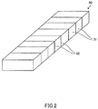
- the magnet body 80 for a field pole accommodated in the slot 22 of the rotor 20 is, as illustrated in Fig. 2 , constituted by an assembly of magnet pieces 31 in which a plurality of magnet pieces 31 are aligned in a row.
- the magnet piece 31 is obtained by division through cleaving of a plate-shaped magnet body 30 covered on the entire circumferential surface with a coating film provided with an anti-rusting effect and having rectangular upper and lower surfaces along a short side direction of the rectangle.
- the magnet body 80 for a field pole is constituted by bonding cleaved surfaces of a plurality of divided magnet pieces 31 to each other by a resin 32.
- the used resin 32 such a resin provided with heat-resistant performances of approximately 200 C, for example, is used, and the adjacent magnet pieces 31 are electrically insulated from each other.
- an eddy current generated in the magnet piece 31 by fluctuation of an acting magnetic field is reduced by retaining it in the individual magnet pieces 31 so as to suppress heat generation of the magnet body 80 for a field pole caused by the eddy current, and irreversible heat demagnetization can be prevented.
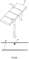
- a fragile portion made of a notched groove 33 or the like in advance in a portion (scheduled cleavage line) to be cleaved of the magnet body 30 as illustrated in Fig. 3 A .
- the notched groove 33 there are a method of providing it in a molding process of the magnet body 30 by a rib for forming a groove provided in a molding die of the magnet body 30, a method using mechanical machining such as a dicer or a slicer, a method by using laser-beam irradiation, wire-cut discharge machining and the like.
- a method using mechanical machining such as a dicer or a slicer
- a method by using laser-beam irradiation, wire-cut discharge machining and the like.
- the magnet body 30 is cleaved along the notched groove 33 into a plurality of magnet pieces 31.
- Figs. 4A and 4B illustrate an outline of a manufacturing device 40 in a comparative example 1 for performing the cleaving process illustrated in Fig. 3C .
- the manufacturing device 40 is a device for cleaving the magnet body 30 by three-point bending by placing the magnet body 30 in a state extended between a pair of dies 41 and 42 and by lowering the blade 43 from an upper part to the extended portion.
- the manufacturing device 40 includes the pair of dies 41 and 42 as a lower die on which the magnet body 30 is placed by being extended, the blade 43 for cleaving the magnet body 30 by pressing the extended portion of the magnet body 30, and a magnet conveying device, not shown, for sequentially conveying the magnet bodies 30 from one end portion to immediately below the blade 43 ( Fig. 4A ).
- the blade 43 cleaves the magnet body 30 by pressing an upper surface of the magnet body 30 extended between the pair of dies 41 and 42 downward.
- the blade 43 is positioned so as to have a tip end located in the middle between the pair of dies 41 and 42 and is driven by a servo press, a machine press, a hydraulic press or the like, for example.
- the manufacturing device 40 is constituted as above, and the magnet body 30 with the notched groove 33 provided is placed by being extended on the upper surfaces of the pair of dies 41 and 42.
- the magnet body 30 is placed on the pair of dies 41 and 42 at a position desired to be cleaved, that is, so that the notched groove 33 provided on the scheduled cleavage line in advance is located on a side faced with the dies 41 and 42 sides.
- the blade 43 is lowered.
- the blade 43 presses the back side of the notched groove 33 downward, and the magnet body 30 is cleaved along the notched groove 33 by the three-point bending of the blade 43 and mutually adjacent edge portions 41a and 42a of the pair of dies 41 and 42 ( Fig. 4B ).
- the coating film 35 covering the surface of the magnet body 30 is cut on a side surface side of the magnet body 30 as the cleavage surface 36 generated by the notched groove 33 progresses, but a state in which the upper surface side of the magnet body 30 in contact with the blade 43 is not cut is generated. That is, the cleaved magnet piece 31 and the magnet body 30 that has not been cleaved are in a state connected by the coating film 35 on the upper surface side that has not been cut.
- the blade 43 is in contact with the coating film 35 on the upper surface side of the magnet body 30 on the portion of the scheduled cleavage line so as to press down this coating film 35 so as to bend it to the lower side, but a tensile force to such a degree to result in cutting of the coating film 35 cannot be obtained by this pressing down.
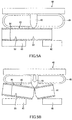
- a magnet presser 45 is pressed onto the magnet body 30 so as to suppress movement of the magnet piece 31, and diffusion of the magnet piece 31 by release of stress at a moment of cleavage is prevented. That is, in the manufacturing device 40 in the comparative example 2, in addition to the manufacturing device 40 in the comparative example 1, the magnet presser 45 moving vertically with the blade 43 is provided.
- the magnet presser 45 is brought into contact with the upper surface of the magnet body 30 and suppresses movement of the magnet body 30 ( Fig. 5A ). If the blade 43 further lowers, the blade 43 presses the back side of the notched groove 33 downward, and the magnet body 30 is cleaved along the notched groove 33 by the three-point bending of the blade 43 and the mutually adjacent edge portions 41a and 42a of the pair of dies 41 and 42 ( Fig. 5B ).
- the coating film 35 on the upper surface side of the magnet body 30 is in contact with the blade 43 and is pressed downward and bent on the portion of the scheduled cleavage line.
- This bent amount is smaller than that in the comparative example 1 since the magnet presser 45 presses the magnet body 30 and the magnet piece 31 from the upper side.
- a tensile force for separating the coating film 35 on the upper surface side of the cleaved magnet piece 31 and the coating film 35 on the upper surface side of the magnet body 30 that has not been cleaved yet from each other becomes weaker, the coating film 35 is not rolled so as to be capable of being cut and is not cut off.
- the cleaving process of the magnet body 30 is performed as follows.
- Figs. 6A to 6D are views illustrating the cleaving process of a manufacturing device 60 in this embodiment.
- the manufacturing device 60 in this embodiment includes a magnet presser 65 similar to the comparative example 2 for preventing diffusion of the magnet piece 31 by stress release at the moment of cleavage.
- the magnet presser 65 of this embodiment is constituted such that its pressing surface 65a is located at a position retreated only by a predetermined distance X from a tip end of the blade 63.
- the magnet presser 65 is constituted so as to have elasticity by bending a thin-plate metal in a shape of a loop as illustrated. Thus, even if the cleaved magnet body 30 and the magnet piece 31 are in contact with the magnet presser 65, they are not chipped.
- This magnet presser 65 is not limited to an elastic body using the aforementioned loop-shaped thin-plate metal but may be formed of other elastic bodies such as rubber (including foamed resin) and the like.
- first, feeding-direction position of the magnet body 30 placed on the pair of dies 61 and 62 is adjusted by a feeding amount of the magnet body 30 so that the notched groove 33 is located immediately below a contact portion 73 of the blade 63 ( Fig. 6A ).
- Conveyance of the magnet body 30 is performed by pushing out the magnet body 30 in the conveying direction by a magnet conveying device 64.
- the magnet conveying device 64 is constituted by an LM guide or the like combining an AC servo motor and a ball screw, for example, and is capable of feeding the magnet body 30 only by a predetermined amount in the feeding direction and stopping it at an arbitrary position.
- the blade 63 In the state in which the magnet body 30 is positioned as above, the blade 63 is lowered. Then, the tip end of the blade 63 is brought into contact with the upper surface of the magnet body 30. Even in this state, the pressing surface 65a of the magnet presser 65 is located above, separated from the upper surface of the magnet body 30.
- the blade 63 When the blade 63 is further lowered, the blade 63 presses a back-surface portion of the notched groove 33 of the magnet body 30 downward, and the magnet body 30 is cleaved along the notched groove 33 by the three-point bending of the blade 63 and the mutually adjacent edge portions 61a and 62a of the pair of dies 61 and 62 ( Fig. 6B ). A start position of a crack generated in cleaving becomes the notched groove 33 which is a fragile portion.
- a lowering speed of the blade 63 is preferably 30 [mm/sec] or more, for example. Then, the blade 63 moves to a lowering end.
- the magnet presser 65 is lowered/moved with the blade 63, and even at the time when the blade 63 has been moved to a lowering end, the pressing surface 65a of the magnet presser 65 holds a distance from the upper surface of the magnet body 30 so as not to be in touch.
- the predetermined distance X from the tip end of the blade 63 described above is set so as to be approximately 2 [mm], for example.
- the distance between the pressing surface 65a of the magnet presser 65 at the lower end and the upper surface of the magnet body 30 is set to such a degree that the magnet presser 65 regulates rotational movement caused by the cleavage between the magnet body 30 and the magnet piece 31 by the middle portion thereof and moreover, each end portion of them can be pushed back downward. Then, by means of the regulation in the middle portion and the action of pushing back, cutting of the coating film 35 being applied is made possible. That is, unlike the form in Fig.
- the pressing surface 65a of the magnet presser 65 is not in touch with the magnet body 30 to be cleaved in an initial state (at start of the cleaving process), but with the rotational movement of the magnet body 30 and the magnet piece 31 after cleavage, they are brought into contact with each end portion of the magnet body 30 and the magnet piece 31 and pushes them back so as to aid cutting of the coating film 35.
- the magnet piece 31 cleaved at the tip end of the magnet body 30 rotationally moves so as to be tilted diagonally with the end portion on the cleavage surface 36 side (rear end side in the conveying direction) directed downward using the edge portion 62a of the die 62 as a fulcrum.
- the magnet body 30 moves an end portion (rear end in the conveying direction) on a side opposite to the cleavage surface 36 upward using the edge portion 61a of the die 61 as a fulcrum and the cleaved magnet piece 31 moves an end portion (front in the conveying direction) on the side opposite to the cleavage surface 36 upward using the edge portion 62a of the die 62 as a fulcrum.
- the movement of each of these end portions is regulated by contact of each of these end portions with the pressing surface 65a of the magnet presser 65 located above each of the end portions and lowering together with the blade 63 in a stage before the blade 63 and the magnet presser 65 reach or almost reach the lowermost stage.
- end portions on the side opposite to the cleavage surface 36 is pressed downward by the magnet presser 65 or bounced back, respectively, and their attitudes are returned by the magnet presser 65 so as to be tilted along support surfaces of the dies 61 and 62, respectively. Since the magnet presser 65 is formed of an elastic body as described above, when the cleaved magnet body 30 and the magnet piece 31 are brought into contact with the magnet presser 65, the cleaved magnet body 30 and the magnet piece 31 are prevented from being chipped.
- This returning movement of the magnet body 30 and the magnet piece 31 acts so that an upper end of the end portion of the magnet piece 31 on the cleavage surface 36 side and an upper end of the end portion of the magnet body 30 on the cleavage surface 36 side are separated from each other and separates the cleavage surface 36 of the magnet body 30 and the cleavage surface 36 of the magnet piece 31 from each other ( Fig. 6C ).
- the coating film 35 on the upper surface sides of the magnet body 30 and the magnet piece 31 is stretched in the separated portion and the coating film 35 on the upper surface side connecting the magnet body 30 and the magnet piece 31 is cut off.
- the magnet body 30 and the magnet piece 31 can be brought into a completely separated state including the coating film 35. Then, the blade 63 is raised ( Fig. 6D ). Subsequently, in order to cleave the subsequent magnet piece 31, the magnet body 30 is fed by the magnet conveying device 64 only for one piece of the magnet piece 31 in the feeding direction, it is cleaved by the similar procedure including the magnet piece 31 and the coating film 35, and the aforementioned procedure is repeated for the required number of cleavages.
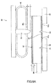
- Figs. 8A to 8C are views illustrating a second embodiment of a manufacturing method and a manufacturing device for manufacturing a magnet piece constituting a magnet body for a field pole disposed on a rotating electric machine to which the present invention is applied, in which Fig. 8A is a schematic configuration diagram illustrating the manufacturing device for manufacturing the magnet piece and Figs. 8B and 8C are explanatory views illustrating its operating state.
- Fig. 8A is a schematic configuration diagram illustrating the manufacturing device for manufacturing the magnet piece
- Figs. 8B and 8C are explanatory views illustrating its operating state.
- constitution in which the magnet presser for pressing the magnet body and the magnet piece is formed by means for ejecting gas (air) is added to the first embodiment.
- the same devices as those in the first embodiment are given the same reference numerals, and the explanation will be omitted or simplified.
- a manufacturing device 60a of this embodiment includes a nozzle plate 66 formed as the magnet presser 65 integrally with the blade 63 and blowing out air toward the magnet body 30 from both side regions of the blade 63.
- the tip end of the blade 63 is constituted so as to be located below a lower surface of the nozzle plate 66 only by the predetermined distance X similarly to the first embodiment.
- the magnet presser 65 of this embodiment includes the nozzle plate 66 and an air reservoir 67.
- the nozzle plate 66 has a large number of nozzle holes 66a formed in a direction perpendicular to the surface of the magnet body 30 and is integrated with the blade 63.
- the air reservoir 67 is provided on a rear surface of the nozzle plate 66 so that supplied air is distributed to nozzle holes 66a of the nozzle plate 66 and supplied.
- air is supplied from an air supply device 68, and the supplied air is distributed by the air reservoir 57 to each of the nozzle holes 66a of the nozzle plate 66 and injected toward the surface of the magnet body 30 through each of the nozzle holes 66a.
- the other constitutions are similarly to those of the first embodiment.
- the cleavage process of the magnet body 30 is performed as follows. That is, similarly to the first embodiment, the magnet body 30 is positioned on the manufacturing device 60a so that the notched groove 33 is located immediately below a contact portion 73 of the blade 63 by adjusting a feeding direction position of the magnet body 30 placed on the pair of dies 61 and 62. Subsequently, the blade 63 is lowered, and the tip end of the blade 63 is brought into contact with the upper surface of the magnet body 30 ( Fig. 8A ). In this state, too, the lower surface of the nozzle plate 66 which is the magnet presser 65 is located above from the upper surface of the magnet body 30, and the air is injected toward the magnet body 30 from the nozzle holes 66a.
- the blade 63 presses the rear surface portion of the notched groove 33 of the magnet body 30 downward, and the magnet body 30 is cleaved along the notched groove 33 by the three-point bending of the blade 63 and the mutually adjacent edge portions 61a and 62a of the pair of dies 61 and 62 ( Fig. 8B ).
- a start position of the crack 35 generated during cleavage becomes the notched groove 33 which is the fragile portion.
- the lowering speed of the blade 63 is preferably 30 [mm/sec] or more, for example. Then, the blade 63 moves to the lowering end.
- the nozzle plate 66 which is the magnet presser 65 is lowered and moved with the blade 63, and even at the point of time when the blade 63 has been moved to the lowering end, the lower surface of the nozzle plate 66 holds a distance from the upper surface of the magnet body 30 so as not to be in touch.
- the distance between the lower surface of the nozzle plate 66 and the upper surface of the magnet body 30 at this lowering end is set so as to be approximately 2 [mm], for example, similarly to the first embodiment. Then, the air injected from the nozzle hole 66a of the nozzle plate 66 flows toward the magnet body 30.
- the cleaved magnet body 30 and the magnet piece 31 are both in the tilted state ( Fig. 8B ). That is, the magnet body 30 immediately after the cleavage rotationally moves so as to be tilted diagonally with the end portion on the cleavage surface 36 side (tip end side in the conveying direction) downward using the edge portion 61a of the die 61 as a fulcrum in the state in contact with the lowered blade 63.
- the magnet piece 31 which has been cleaved at the tip end of the magnet body 30 rotationally moves so as to be tilted diagonally with the end portion on the cleavage surface 36 side (rear end side in the conveying direction) downward using the edge portion 62a of the die 62 as a fulcrum.
- the coating film 35 between the magnet body 30 and the magnet piece 31 on its tip end side is cut by the cleavage surface 36 generated by the notched groove 33 on the lower surface sides and the side surface sides of the magnet body 30 and the magnet piece 31 but is not cut on the upper surface side of the magnet body 30.
- the magnet body 30 moves an end portion (rear end in the conveying direction) on the side opposite to the cleavage surface 36 side upward using the edge portion 61 a of the die 61 as a fulcrum and the cleaved magnet piece 31 moves an end portion (front in the conveying direction) on the side opposite to the cleavage surface 36 side upward using the edge portion 62a of the die 62 as a fulcrum.
- the movement of each of these end portions is performed against the action of pushing back by the air jet injected from the nozzle plate 66 located above them and lowering with the blade 63.
- each of the magnet body 30 and the magnet piece 31 is pressed downward or bounced back by the air jet from the nozzle plate 66 and their attitude is returned so as to be tilted along the support surfaces of the respective dies 61 and 62. Since the magnet presser 65 is formed by the nozzle plate 66 injecting the air, contact of the cleaved magnet body 30 and the magnet piece 31 with the nozzle plate 66 can be suppressed, and the cleaved magnet body 30 and the magnet piece 31 are prevented from being chipped.
- This returning movement of the magnet body 30 and the magnet piece 31 acts so that the upper end of the end portion of the magnet piece 31 on the cleavage surface 36 side and the upper end of the end portion of the magnet body 30 on the cleavage surface 36 side are separated from each other and separates the cleavage surface 36 of the magnet body 30 and the cleavage surface 36 of the magnet piece 31 from each other ( Fig. 8C ).
- the coating film 35 on the upper surface sides of the magnet body 30 and the magnet piece 31 is stretched in the separated portion and the coating film 35 on the upper surface side connecting the magnet body 30 and the magnet piece 31 is cut off at the separated portion.
Landscapes
- Engineering & Computer Science (AREA)
- Power Engineering (AREA)
- Manufacturing & Machinery (AREA)
- Life Sciences & Earth Sciences (AREA)
- Forests & Forestry (AREA)
- Mechanical Engineering (AREA)
- Environmental & Geological Engineering (AREA)
- Permanent Field Magnets Of Synchronous Machinery (AREA)
- Manufacturing Cores, Coils, And Magnets (AREA)
Description
- The present invention relates to a manufacture method and a manufacturing device for manufacturing a magnet piece constituting a magnet body for a field pole disposed on a rotating electric machine.
- Conventionally, as a magnet body for a field pole disposed on a rotating electric machine, a magnet body for a field pole formed by providing a plurality of magnet pieces by cleaving a plate-shaped magnet body (hereinafter referred to simply as a "magnet body") and by bonding a plurality of the magnet pieces to each other is known. Since such magnet body for a field pole is formed of a plurality of the magnet pieces, a volume of each magnet piece can be made small, and an eddy current generated in the magnet piece by fluctuation of a magnetic field by rotation of a rotor can be reduced. As a result, heat generation of the magnet body for a field pole caused by generation of the eddy current can be suppressed, and irreversible heat demagnetization can be prevented (see Patent Literature 1).
-
JP2009-142081A - The magnet body is fed on the die in a longitudinal direction and cleaved by the blade one by one sequentially from a tip end portion in a feeding direction. The magnet body is cleaved by pressing the blade downward from the upper part of the scheduled cleavage line in a state in which the both sides of the scheduled cleavage line are supported by the die. That is, the magnet body is cleaved by three-point bending.
- The magnet body has a nature that it is apt to rust, and the surface of the magnet body is coated with a material having an anti-rusting effect. Since the material of this coating film is a ductile material, the coating film is not rolled to a state capable of being cut in a portion of the scheduled cleavage line during cleavage of the magnet body, and the coating film is not cut in some cases. If the coating film is not cut, a cleaved magnet piece and a magnet piece which has not been cut are connected by the uncut coating film. As a result, when the cleaved magnet pieces are conveyed to a subsequent process, nonconformity that the magnet body that has not been cut is also conveyed at the same time occurs incidentally.
- The present invention was made in view of the aforementioned problem and has an object to provide a manufacture method and a manufacturing device suitable for manufacture of a magnet piece constituting a magnet body for a field pole disposed on a rotating electric machine by cleaving the magnet body provided with a coating film.
- According to one aspect of the present invention, the present invention provides a manufacture method. The manufacture method of manufacturing a magnet piece constituting a magnet body for a field pole disposed on a rotating machine by cleaving a permanent magnet body. The manufacture method includes positioning the permanent magnet body of which a surface is coated with a coating film for deterioration prevention, a scheduled cleavage portion of the permanent magnet being located between two fulcrums supporting the permanent magnet body, cleaving the permanent magnet body into a cleaved magnet body and the magnet piece by pressing the scheduled cleavage portion of the permanent magnet body, and cutting the coating-film between the cleaved magnet body and the magnet piece by pressing an end portion of the cleaved magnet piece from a direction in which the scheduled cleavage portion is pressed, the end portion being on a side opposite to a cleavage surface side.
-
- [
Fig. 1A] Fig. 1A is a schematic configuration view illustrating configuration of major portions of a permanent-magnet rotating electric machine to which a magnet body for a field pole constituted by a magnet piece manufactured by a manufacture method and a manufacturing device in this embodiment is applied. - [
Fig. 1B] Fig. 1B is a sectional view illustrating an I-I section of the permanent-magnet rotating electric machine inFig. 1A . - [
Fig. 2] Fig. 2 is a configuration view illustrating configuration of the magnet body for a field pole. - [
Fig. 3A] Fig. 3A is a view for illustrating a grooving process of the magnet body. - [
Fig. 3B] Fig. 3B is a view for illustrating a deburring process of the magnet body. - [
Fig. 3C] Fig. 3C is a view for illustrating a cleaving process of the magnet body. - [
Fig. 4A] Fig. 4A is a view illustrating the cleaving process of a manufacturing device in a comparative example 1. - [
Fig. 4B] Fig. 4B is a view illustrating the cleaving process of the manufacturing device in the comparative example 1. - [
Fig. 5A] Fig. 5A is a view illustrating the cleaving process of a manufacturing device in a comparative example 2. - [
Fig. 5B] Fig. 5B is a view illustrating the cleaving process of the manufacturing device in the comparative example 2. - [
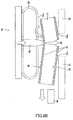
Fig. 5C] Fig. 5C is a view illustrating the cleaving process of the manufacturing device in the comparative example 2. - [
Fig. 6A] Fig. 6A is a view illustrating the cleaving process of a manufacturing device in a first embodiment. - [
Fig. 6B] Fig. 6B is a view illustrating the cleaving process of the manufacturing device in the first embodiment. - [
Fig. 6C] Fig. 6C is a view illustrating the cleaving process of the manufacturing device in the first embodiment. - [
Fig. 6D] Fig. 6D is a view illustrating the cleaving process of the manufacturing device in the first embodiment. - [
Fig. 7] Fig. 7 is a schematic configuration diagram illustrating another embodiment of the manufacturing device in the first embodiment. - [
Fig. 8A] Fig. 8A is a view illustrating the cleaving process of a manufacturing device in a second embodiment. - [
Fig. 8B] Fig. 8B is a view illustrating the cleaving process of the manufacturing device in the second embodiment. - [
Fig. 8C] Fig. 8C is a view illustrating the cleaving process of the manufacturing device in the second embodiment. - Embodiments of the present invention will be described below by referring to the attached drawings.
-
Fig. 1A andFig. 1B illustrating an I-I section ofFig. 1A illustrate a permanent magnet embedded rotating electric machine A (hereinafter referred to simply as a "rotating electric machine A") to which amagnet body 80 for a field pole constituted of a magnet piece manufactured by the manufacture method and the manufacturing device in this embodiment is applied. - The rotating electric machine A includes a ring-shaped
stator 10 constituting a part of a casing and a columnar-shapedrotor 20 arranged coaxially with thisstator 10. - The
stator 10 includes astator core 11 and a plurality ofcoils 12. A plurality ofcoils 12 are accommodated inslots 13 formed in thestator core 11 at an equal angle interval on the same circumference around an axis center O. - The
rotor 20 is constituted by arotor core 21, a rotatingshaft 23 rotating integrally with therotor core 21, and a plurality ofmagnet bodies 80 for a field pole, and a plurality ofmagnet bodies 80 for a field pole are accommodated inslots 22 formed at an equal angle interval on the same circumference around the axis center O. - The
magnet body 80 for a field pole accommodated in theslot 22 of therotor 20 is, as illustrated inFig. 2 , constituted by an assembly ofmagnet pieces 31 in which a plurality ofmagnet pieces 31 are aligned in a row. Themagnet piece 31 is obtained by division through cleaving of a plate-shapedmagnet body 30 covered on the entire circumferential surface with a coating film provided with an anti-rusting effect and having rectangular upper and lower surfaces along a short side direction of the rectangle. Themagnet body 80 for a field pole is constituted by bonding cleaved surfaces of a plurality of dividedmagnet pieces 31 to each other by aresin 32. As the usedresin 32, such a resin provided with heat-resistant performances of approximately 200 C, for example, is used, and theadjacent magnet pieces 31 are electrically insulated from each other. As a result, an eddy current generated in themagnet piece 31 by fluctuation of an acting magnetic field is reduced by retaining it in theindividual magnet pieces 31 so as to suppress heat generation of themagnet body 80 for a field pole caused by the eddy current, and irreversible heat demagnetization can be prevented. - Subsequently, by referring to
Figs. 3A to 3C , a process of manufacturing a plurality of themagnet pieces 31 from the plate-shapedmagnet body 30 covered on the entire circumferential surface with thecoating film 35 provided with the anti-rusting effect will be described. - In order to cleave the
magnet body 30 into a plurality ofmagnet pieces 31, it is effective to form a fragile portion made of a notchedgroove 33 or the like in advance in a portion (scheduled cleavage line) to be cleaved of themagnet body 30 as illustrated inFig. 3 A . The deeper a depth of the notchedgroove 33 provided as a fragile portion from the surface is, or the sharper an angle of a bottom portion of the notchedgroove 33 is, the more flatness of acleavage surface 36 obtained by being cleaved as themagnet piece 31 is improved. - As a method for forming the notched
groove 33, there are a method of providing it in a molding process of themagnet body 30 by a rib for forming a groove provided in a molding die of themagnet body 30, a method using mechanical machining such as a dicer or a slicer, a method by using laser-beam irradiation, wire-cut discharge machining and the like. When the notchedgroove 33 is formed by mechanical machining, the laser-beam irradiation and the wire-cut discharge machining, thecoating film 35 on the surface of themagnet body 30 is also formed by notching at the same time. - When the notched
groove 33 is formed by the laser-beam irradiation or the wire-cut discharge machining, since aburr 34 is generated along the notchedgroove 33, thisburr 34 is removed by a deburring process as illustrated inFig. 3B . - Subsequently, in a cleaving process, by pressing a position corresponding to the
groove 33 by a blade which will be described later from a side without the notchedgroove 33 in a state with the notchedgroove 33 directed downward, as illustrated inFig. 3C , themagnet body 30 is cleaved along the notchedgroove 33 into a plurality ofmagnet pieces 31. -
Figs. 4A and 4B illustrate an outline of amanufacturing device 40 in a comparative example 1 for performing the cleaving process illustrated inFig. 3C . - The
manufacturing device 40 is a device for cleaving themagnet body 30 by three-point bending by placing themagnet body 30 in a state extended between a pair of dies 41 and 42 and by lowering theblade 43 from an upper part to the extended portion. Themanufacturing device 40 includes the pair of dies 41 and 42 as a lower die on which themagnet body 30 is placed by being extended, theblade 43 for cleaving themagnet body 30 by pressing the extended portion of themagnet body 30, and a magnet conveying device, not shown, for sequentially conveying themagnet bodies 30 from one end portion to immediately below the blade 43 (Fig. 4A ). - The
blade 43 cleaves themagnet body 30 by pressing an upper surface of themagnet body 30 extended between the pair of dies 41 and 42 downward. Theblade 43 is positioned so as to have a tip end located in the middle between the pair of dies 41 and 42 and is driven by a servo press, a machine press, a hydraulic press or the like, for example. - The
manufacturing device 40 is constituted as above, and themagnet body 30 with the notchedgroove 33 provided is placed by being extended on the upper surfaces of the pair of dies 41 and 42. Themagnet body 30 is placed on the pair of dies 41 and 42 at a position desired to be cleaved, that is, so that the notchedgroove 33 provided on the scheduled cleavage line in advance is located on a side faced with the dies 41 and 42 sides. - Then, by the magnet conveying device, not shown, in a state in which the notched
groove 33 as the scheduled cleavage line is aligned so as to be located in the middle between the pair of dies 41 and 42, theblade 43 is lowered. When theblade 43 is lowered, theblade 43 presses the back side of the notchedgroove 33 downward, and themagnet body 30 is cleaved along the notchedgroove 33 by the three-point bending of theblade 43 and mutually adjacent edge portions 41a and 42a of the pair of dies 41 and 42 (Fig. 4B ). - At this time, the
coating film 35 covering the surface of themagnet body 30 is cut on a side surface side of themagnet body 30 as thecleavage surface 36 generated by the notchedgroove 33 progresses, but a state in which the upper surface side of themagnet body 30 in contact with theblade 43 is not cut is generated. That is, the cleavedmagnet piece 31 and themagnet body 30 that has not been cleaved are in a state connected by thecoating film 35 on the upper surface side that has not been cut. - As a reason why the cleaved
magnet piece 31 and themagnet body 30 that has not been cut are in the state connected by thecoating film 35 as above, formation of thecoating film 35 by a ductile material can be cited, first. Moreover, in themanufacturing device 40 in the comparative example 1, during cleavage of themagnet body 30, theblade 43 is in contact with thecoating film 35 on the upper surface side of themagnet body 30 on the portion of the scheduled cleavage line so as to press down thiscoating film 35 so as to bend it to the lower side, but a tensile force to such a degree to result in cutting of thecoating film 35 cannot be obtained by this pressing down. - The aforementioned problem is made more remarkable in the
manufacturing device 40 of a comparative example 2 illustrated inFigs. 5A to 5C . In themanufacturing device 40 illustrated in theseFigs. 5A to 5C , amagnet presser 45 is pressed onto themagnet body 30 so as to suppress movement of themagnet piece 31, and diffusion of themagnet piece 31 by release of stress at a moment of cleavage is prevented. That is, in themanufacturing device 40 in the comparative example 2, in addition to themanufacturing device 40 in the comparative example 1, themagnet presser 45 moving vertically with theblade 43 is provided. - In the state in which the notched
groove 33 as the scheduled cleavage line is aligned so as to be located in the middle between the pair of dies 41 and 42 by the magnet conveying device, not shown, as theblade 43 lowers, first, themagnet presser 45 is brought into contact with the upper surface of themagnet body 30 and suppresses movement of the magnet body 30 (Fig. 5A ). If theblade 43 further lowers, theblade 43 presses the back side of the notchedgroove 33 downward, and themagnet body 30 is cleaved along the notchedgroove 33 by the three-point bending of theblade 43 and the mutually adjacent edge portions 41a and 42a of the pair of dies 41 and 42 (Fig. 5B ). - At this time, the
coating film 35 on the upper surface side of themagnet body 30 is in contact with theblade 43 and is pressed downward and bent on the portion of the scheduled cleavage line. This bent amount is smaller than that in the comparative example 1 since themagnet presser 45 presses themagnet body 30 and themagnet piece 31 from the upper side. Thus, a tensile force for separating thecoating film 35 on the upper surface side of the cleavedmagnet piece 31 and thecoating film 35 on the upper surface side of themagnet body 30 that has not been cleaved yet from each other becomes weaker, thecoating film 35 is not rolled so as to be capable of being cut and is not cut off. - Then, with the subsequent rise of the
blade 43, in the state in which themagnet body 30 and themagnet piece 31 are connected by thecoating film 35 on the upper surface side that has not been cut, they return from the bent state by the magnet presser 45 (Fig. 5C ). - Thus, in this embodiment, the cleaving process of the
magnet body 30 is performed as follows. -
Figs. 6A to 6D are views illustrating the cleaving process of amanufacturing device 60 in this embodiment. Themanufacturing device 60 in this embodiment includes amagnet presser 65 similar to the comparative example 2 for preventing diffusion of themagnet piece 31 by stress release at the moment of cleavage. However, themagnet presser 65 of this embodiment is constituted such that itspressing surface 65a is located at a position retreated only by a predetermined distance X from a tip end of theblade 63. Themagnet presser 65 is constituted so as to have elasticity by bending a thin-plate metal in a shape of a loop as illustrated. Thus, even if thecleaved magnet body 30 and themagnet piece 31 are in contact with themagnet presser 65, they are not chipped. Thismagnet presser 65 is not limited to an elastic body using the aforementioned loop-shaped thin-plate metal but may be formed of other elastic bodies such as rubber (including foamed resin) and the like. - In this embodiment, first, feeding-direction position of the
magnet body 30 placed on the pair of dies 61 and 62 is adjusted by a feeding amount of themagnet body 30 so that the notchedgroove 33 is located immediately below a contact portion 73 of the blade 63 (Fig. 6A ). Conveyance of themagnet body 30 is performed by pushing out themagnet body 30 in the conveying direction by amagnet conveying device 64. Themagnet conveying device 64 is constituted by an LM guide or the like combining an AC servo motor and a ball screw, for example, and is capable of feeding themagnet body 30 only by a predetermined amount in the feeding direction and stopping it at an arbitrary position. - In the state in which the
magnet body 30 is positioned as above, theblade 63 is lowered. Then, the tip end of theblade 63 is brought into contact with the upper surface of themagnet body 30. Even in this state, thepressing surface 65a of themagnet presser 65 is located above, separated from the upper surface of themagnet body 30. - When the
blade 63 is further lowered, theblade 63 presses a back-surface portion of the notchedgroove 33 of themagnet body 30 downward, and themagnet body 30 is cleaved along the notchedgroove 33 by the three-point bending of theblade 63 and the mutuallyadjacent edge portions Fig. 6B ). A start position of a crack generated in cleaving becomes the notchedgroove 33 which is a fragile portion. A lowering speed of theblade 63 is preferably 30 [mm/sec] or more, for example. Then, theblade 63 moves to a lowering end. - In this cleavage of the
magnetic body 30, themagnet presser 65 is lowered/moved with theblade 63, and even at the time when theblade 63 has been moved to a lowering end, thepressing surface 65a of themagnet presser 65 holds a distance from the upper surface of themagnet body 30 so as not to be in touch. Regarding the distance between thepressing surface 65a of themagnet presser 65 and the upper surface of themagnet body 30 at this lowering end, the predetermined distance X from the tip end of theblade 63 described above is set so as to be approximately 2 [mm], for example. The distance between thepressing surface 65a of themagnet presser 65 at the lower end and the upper surface of themagnet body 30 is set to such a degree that themagnet presser 65 regulates rotational movement caused by the cleavage between themagnet body 30 and themagnet piece 31 by the middle portion thereof and moreover, each end portion of them can be pushed back downward. Then, by means of the regulation in the middle portion and the action of pushing back, cutting of thecoating film 35 being applied is made possible. That is, unlike the form inFig. 5B , thepressing surface 65a of themagnet presser 65 is not in touch with themagnet body 30 to be cleaved in an initial state (at start of the cleaving process), but with the rotational movement of themagnet body 30 and themagnet piece 31 after cleavage, they are brought into contact with each end portion of themagnet body 30 and themagnet piece 31 and pushes them back so as to aid cutting of thecoating film 35. - In the following, a process to this cutting of the
coating film 35 will be described in more detail. Themagnet body 30 immediately after the cleavage rotationally moves so as to be tilted diagonally with an end portion on thecleavage surface 36 side (tip end side in the conveying direction) directed downward using theedge portion 61a of the die 61 as a fulcrum in a state in contact with the loweredblade 63. Moreover, themagnet piece 31 cleaved at the tip end of themagnet body 30 rotationally moves so as to be tilted diagonally with the end portion on thecleavage surface 36 side (rear end side in the conveying direction) directed downward using theedge portion 62a of the die 62 as a fulcrum. At this point of time, though thecoating film 35 between themagnet body 30 and themagnet piece 31 is cut by thecleavage surface 36 generated by the notchedgroove 33 on lower surface sides and side surface sides of themagnet body 30 and themagnet piece 31 but has not been cut yet on the upper surface sides of themagnet body 30 and themagnet piece 31. - By means of this rotational movement, the
magnet body 30 moves an end portion (rear end in the conveying direction) on a side opposite to thecleavage surface 36 upward using theedge portion 61a of the die 61 as a fulcrum and the cleavedmagnet piece 31 moves an end portion (front in the conveying direction) on the side opposite to thecleavage surface 36 upward using theedge portion 62a of the die 62 as a fulcrum. The movement of each of these end portions is regulated by contact of each of these end portions with thepressing surface 65a of themagnet presser 65 located above each of the end portions and lowering together with theblade 63 in a stage before theblade 63 and themagnet presser 65 reach or almost reach the lowermost stage. Regarding themagnet body 30 and themagnet piece 31, end portions on the side opposite to thecleavage surface 36 is pressed downward by themagnet presser 65 or bounced back, respectively, and their attitudes are returned by themagnet presser 65 so as to be tilted along support surfaces of the dies 61 and 62, respectively. Since themagnet presser 65 is formed of an elastic body as described above, when thecleaved magnet body 30 and themagnet piece 31 are brought into contact with themagnet presser 65, thecleaved magnet body 30 and themagnet piece 31 are prevented from being chipped. - This returning movement of the
magnet body 30 and themagnet piece 31 acts so that an upper end of the end portion of themagnet piece 31 on thecleavage surface 36 side and an upper end of the end portion of themagnet body 30 on thecleavage surface 36 side are separated from each other and separates thecleavage surface 36 of themagnet body 30 and thecleavage surface 36 of themagnet piece 31 from each other (Fig. 6C ). By means of this separating movement, thecoating film 35 on the upper surface sides of themagnet body 30 and themagnet piece 31 is stretched in the separated portion and thecoating film 35 on the upper surface side connecting themagnet body 30 and themagnet piece 31 is cut off. - Then, the
magnet body 30 and themagnet piece 31 can be brought into a completely separated state including thecoating film 35. Then, theblade 63 is raised (Fig. 6D ). Subsequently, in order to cleave thesubsequent magnet piece 31, themagnet body 30 is fed by themagnet conveying device 64 only for one piece of themagnet piece 31 in the feeding direction, it is cleaved by the similar procedure including themagnet piece 31 and thecoating film 35, and the aforementioned procedure is repeated for the required number of cleavages. - In the aforementioned embodiment, constitution having elasticity by bending thin-plate metal in a loop shape as the
magnet presser 65 is described. However, even if themagnet presser 65 is brought into contact with thecleaved magnet body 30 and themagnet piece 31, another softelastic body 65b may be provided on thepressing surface 65a of themagnet presser 65 as illustrated inFig. 7 in order to further prevent them from being chipped. - Moreover, in the aforementioned embodiment, as the cleaving process, cleavage into the
magnet body 30 after cleavage and themagnet piece 31 smaller than themagnet body 30 after cleavage by pressing the scheduled cleavage portion of thepermanent magnet body 30 is described. However, as thepermanent magnet body 30 is sequentially cleaved by a plurality of scheduled cleavage portions, a size of themagnet body 30 after cleavage becomes small and finally, the sizes of themagnet body 30 after cleavage and themagnet piece 31 become equal. Therefore, including the cleavage of thepermanent magnet body 30 into halves by the scheduled cleavage portion, themagnet body 30 after cleavage and themagnet piece 31 having the equal size are also included in the present invention. - In this embodiment, effects described below can be exerted.
- (A) A process of positioning the
permanent magnet body 30 of which a surface is coated with thecoating film 35 for deterioration prevention so that its scheduled cleavage portion is located between the two fulcrums (theedge portions permanent magnet body 30 and a cleavage process of cleaving themagnet body 30 after cleavage and themagnet piece 31 by pressing the scheduled cleavage portion of thepermanent magnet body 30 are provided. Then, subsequently to the cleavage process, a coating-film cutting process of cutting thecoating film 35 between thecleaved magnet body 30 and themagnet piece 31 by pressing the end portion of themagnet piece 31 cleaved in the cleaving process from a pressing side of the scheduled cleavage portion is provided. The end portion is on side opposite to the cleavage surface side. Particularly in this embodiment, in the positioning process, thepressing surface 65a of themagnet presser 65 is constituted with a distance from the upper surface of themagnet body 30 so as not to be in contact, and in the middle or after the end of the cleavage process, the end portion of themagnet piece 31 on the side opposite to thecleavage surface 36 side is pressed from the side pressing the scheduled cleavage portion for the first time.
Therefore, themagnet piece 31 rotates by moving the end portion on the side opposite to thecleavage surface 36 upward with the cleavage, but the end portion is pressed downward or bounced back by the contact with the loweredmagnet presser 65 and the attitude thereof is returned by themagnet presser 65 so as to be tilted along the support surface of thedie 62. As a result, it acts so that the upper end of the end portion of themagnet piece 31 on thecleavage surface 36 side and the upper end of the end portion of themagnet body 30 on thecleavage surface 36 side are separated from each other and separates thecleavage surface 36 of themagnet body 30 and thecleavage surface 36 of themagnet piece 31 from each other. By means of this separating movement, thecoating film 35 on the upper surface sides of themagnet body 30 and themagnet piece 31 is stretched, and thecoating film 35 on the upper surface side connecting themagnet body 30 and themagnet piece 31 can be cut off. - (B) The coating-film cutting process is performed by pressing the end portion of the
magnet piece 31 on the side opposite to thecleavage surface 36 side by themagnet presser 65 formed of an elastic body. Thus, when thecleaved magnet body 30 and themagnet piece 31 are brought into contact with themagnet presser 65, thecleaved magnet body 30 and themagnet piece 31 are prevented from being chipped. -
Figs. 8A to 8C are views illustrating a second embodiment of a manufacturing method and a manufacturing device for manufacturing a magnet piece constituting a magnet body for a field pole disposed on a rotating electric machine to which the present invention is applied, in whichFig. 8A is a schematic configuration diagram illustrating the manufacturing device for manufacturing the magnet piece andFigs. 8B and8C are explanatory views illustrating its operating state. In this embodiment, constitution in which the magnet presser for pressing the magnet body and the magnet piece is formed by means for ejecting gas (air) is added to the first embodiment. The same devices as those in the first embodiment are given the same reference numerals, and the explanation will be omitted or simplified. - In
Fig. 8A , amanufacturing device 60a of this embodiment includes anozzle plate 66 formed as themagnet presser 65 integrally with theblade 63 and blowing out air toward themagnet body 30 from both side regions of theblade 63. In this embodiment, too, the tip end of theblade 63 is constituted so as to be located below a lower surface of thenozzle plate 66 only by the predetermined distance X similarly to the first embodiment. - The
magnet presser 65 of this embodiment includes thenozzle plate 66 and anair reservoir 67. Thenozzle plate 66 has a large number ofnozzle holes 66a formed in a direction perpendicular to the surface of themagnet body 30 and is integrated with theblade 63. Theair reservoir 67 is provided on a rear surface of thenozzle plate 66 so that supplied air is distributed tonozzle holes 66a of thenozzle plate 66 and supplied. To theair reservoir 67, air is supplied from anair supply device 68, and the supplied air is distributed by the air reservoir 57 to each of the nozzle holes 66a of thenozzle plate 66 and injected toward the surface of themagnet body 30 through each of thenozzle holes 66a. The other constitutions are similarly to those of the first embodiment. - In this embodiment, the cleavage process of the
magnet body 30 is performed as follows. That is, similarly to the first embodiment, themagnet body 30 is positioned on themanufacturing device 60a so that the notchedgroove 33 is located immediately below a contact portion 73 of theblade 63 by adjusting a feeding direction position of themagnet body 30 placed on the pair of dies 61 and 62. Subsequently, theblade 63 is lowered, and the tip end of theblade 63 is brought into contact with the upper surface of the magnet body 30 (Fig. 8A ). In this state, too, the lower surface of thenozzle plate 66 which is themagnet presser 65 is located above from the upper surface of themagnet body 30, and the air is injected toward themagnet body 30 from thenozzle holes 66a. - Moreover, when the
blade 63 is lowered, as illustrated inFig. 8B , theblade 63 presses the rear surface portion of the notchedgroove 33 of themagnet body 30 downward, and themagnet body 30 is cleaved along the notchedgroove 33 by the three-point bending of theblade 63 and the mutuallyadjacent edge portions Fig. 8B ). A start position of thecrack 35 generated during cleavage becomes the notchedgroove 33 which is the fragile portion. The lowering speed of theblade 63 is preferably 30 [mm/sec] or more, for example. Then, theblade 63 moves to the lowering end. - In this cleavage of the
magnet body 30, too, thenozzle plate 66 which is themagnet presser 65 is lowered and moved with theblade 63, and even at the point of time when theblade 63 has been moved to the lowering end, the lower surface of thenozzle plate 66 holds a distance from the upper surface of themagnet body 30 so as not to be in touch. The distance between the lower surface of thenozzle plate 66 and the upper surface of themagnet body 30 at this lowering end is set so as to be approximately 2 [mm], for example, similarly to the first embodiment. Then, the air injected from thenozzle hole 66a of thenozzle plate 66 flows toward themagnet body 30. - The
cleaved magnet body 30 and themagnet piece 31 are both in the tilted state (Fig. 8B ). That is, themagnet body 30 immediately after the cleavage rotationally moves so as to be tilted diagonally with the end portion on thecleavage surface 36 side (tip end side in the conveying direction) downward using theedge portion 61a of the die 61 as a fulcrum in the state in contact with the loweredblade 63. Moreover, themagnet piece 31 which has been cleaved at the tip end of themagnet body 30 rotationally moves so as to be tilted diagonally with the end portion on thecleavage surface 36 side (rear end side in the conveying direction) downward using theedge portion 62a of the die 62 as a fulcrum. At this point of time, thecoating film 35 between themagnet body 30 and themagnet piece 31 on its tip end side is cut by thecleavage surface 36 generated by the notchedgroove 33 on the lower surface sides and the side surface sides of themagnet body 30 and themagnet piece 31 but is not cut on the upper surface side of themagnet body 30. - By means of this rotational movement, the
magnet body 30 moves an end portion (rear end in the conveying direction) on the side opposite to thecleavage surface 36 side upward using theedge portion 61 a of the die 61 as a fulcrum and the cleavedmagnet piece 31 moves an end portion (front in the conveying direction) on the side opposite to thecleavage surface 36 side upward using theedge portion 62a of the die 62 as a fulcrum. The movement of each of these end portions is performed against the action of pushing back by the air jet injected from thenozzle plate 66 located above them and lowering with theblade 63. Thus, in a stage before theblade 63 and thenozzle plate 66 reach or almost reach the lowermost stage, the aforementioned movement is regulated. Then, each of themagnet body 30 and themagnet piece 31 is pressed downward or bounced back by the air jet from thenozzle plate 66 and their attitude is returned so as to be tilted along the support surfaces of the respective dies 61 and 62. Since themagnet presser 65 is formed by thenozzle plate 66 injecting the air, contact of thecleaved magnet body 30 and themagnet piece 31 with thenozzle plate 66 can be suppressed, and thecleaved magnet body 30 and themagnet piece 31 are prevented from being chipped. - This returning movement of the
magnet body 30 and themagnet piece 31 acts so that the upper end of the end portion of themagnet piece 31 on thecleavage surface 36 side and the upper end of the end portion of themagnet body 30 on thecleavage surface 36 side are separated from each other and separates thecleavage surface 36 of themagnet body 30 and thecleavage surface 36 of themagnet piece 31 from each other (Fig. 8C ). By means of this separating movement, thecoating film 35 on the upper surface sides of themagnet body 30 and themagnet piece 31 is stretched in the separated portion and thecoating film 35 on the upper surface side connecting themagnet body 30 and themagnet piece 31 is cut off at the separated portion. - In this embodiment, in addition to the effects (A) and (B) in the first embodiment, the effects described below can be exerted.
- (C) The coating-film cutting process is performed by pressing the end portion on the side opposite to the
cleavage surface 36 side of themagnet piece 31 by an air jet. Themagnet piece 31 rotates by moving the end portion on the side opposite to thecleavage surface 36 side upward with the cleavage, but the end portion is pressed downward or bounced back by the air jet from the lowerednozzle plate 66 and the attitude thereof is returned so as to be tilted along the support surface of thedie 62. That is, since themagnet presser 65 is formed by thenozzle plate 66 injecting the air, by means of the aforementioned action that contact of the cleavedmagnet piece 31 with thenozzle plate 66 can be suppressed, and chipping of the cleavedmagnet piece 31 can be prevented, the upper end of the end portion of themagnet piece 31 on thecleavage surface 36 side and the upper end of the end portion of themagnet body 30 on thecleavage surface 36 side are separated, thecleavage surface 36 of themagnet body 30 and thecleavage surface 36 of themagnet piece 31 are separated from each other, and thecoating film 35 on the upper surface sides of themagnet body 30 and themagnet piece 31 is stretched in the separation portion . Thus, thecoating film 35 on the upper surface side connecting themagnet body 30 and themagnet piece 31 can be cut off at the separated portion. - The embodiments of the present invention has been described, but the embodiments only illustrate a part of application examples of the present invention and are not intended to limit the technical scope of the present invention to the specific constitution of the embodiments.
- The present application claims a priority of Japanese Patent Application No.
2013-211769
Claims (6)
- A manufacture method of manufacturing a magnet piece constituting a magnet body for a field pole disposed on a rotating machine by cleaving a permanent magnet body, comprising:positioning the permanent magnet body of which a surface is coated with a coating film for deterioration prevention, a scheduled cleavage portion of the permanent magnet body being located between two fulcrums supporting the permanent magnet body;cleaving the permanent magnet body into a cleaved magnet body and the magnet piece by pressing the scheduled cleavage portion of the permanent magnet body; andcutting the coating-film between the cleaved magnet body and the magnet piece by pressing an end portion of the cleaved magnet piece from a pressing side of the scheduled cleavage portion, the end portion being on a side opposite to a cleavage surface side.
- The manufacture method according to claim 1, wherein
the cutting the coating film is performed by pressing the end portion of the magnet piece on the side opposite to the cleavage surface side by an elastic body. - The manufacture method according to claim 1, wherein
the cutting the coating film is performed by pressing the end portion of the magnet piece on the side opposite to the cleavage surface side by an air jet. - A manufacturing device for manufacturing a magnet piece constituting a magnet body for a field pole disposed on a rotating electric machine by cleaving a permanent magnet body, comprising:a support portion supporting the permanent magnet body of which a surface is coated with a coating film for deterioration prevention on two fulcrums on both sides of a scheduled cleavage portion of the permanent magnet body;cleaving unit configured to cleave the magnet body into a cleaved magnet body and the magnet piece by pressing the scheduled cleavage portion of the permanent magnet body between the both fulcrums; andcoating-film cutting unit configured to cut the coating-film between the cleaved magnet body and the magnet piece by pressing an end portion of the cleaved magnet piece from a pressing side of the scheduled cleavage portion, the end portion being on a side opposite to a cleavage surface side.
- The manufacturing device according to claim 4, wherein
the coating-film cutting unit is performed by pressing an end portion of the magnet piece on a side opposite to the cleavage surface side by an elastic body. - The manufacturing device according to claim 4, wherein
the coating-film cutting unit is performed by pressing an end portion of the magnet piece on a side opposite to the cleavage surface side by an air jet.
Applications Claiming Priority (2)
| Application Number | Priority Date | Filing Date | Title |
|---|---|---|---|
| JP2013211769 | 2013-10-09 | ||
| PCT/JP2014/069970 WO2015052976A1 (en) | 2013-10-09 | 2014-07-29 | Method and device for manufacturing magnet pieces configuring a field pole magnet to be arranged in a rotary machine |
Publications (3)
| Publication Number | Publication Date |
|---|---|
| EP3057207A1 true EP3057207A1 (en) | 2016-08-17 |
| EP3057207A4 EP3057207A4 (en) | 2016-09-14 |
| EP3057207B1 EP3057207B1 (en) | 2018-10-10 |
Family
ID=52812797
Family Applications (1)
| Application Number | Title | Priority Date | Filing Date |
|---|---|---|---|
| EP14851916.8A Active EP3057207B1 (en) | 2013-10-09 | 2014-07-29 | Method and device for manufacturing magnet pieces configuring a field pole magnet to be arranged in a rotary machine |
Country Status (5)
| Country | Link |
|---|---|
| US (1) | US10279504B2 (en) |
| EP (1) | EP3057207B1 (en) |
| JP (1) | JP6112216B2 (en) |
| CN (1) | CN105594107B (en) |
| WO (1) | WO2015052976A1 (en) |
Families Citing this family (5)
| Publication number | Priority date | Publication date | Assignee | Title |
|---|---|---|---|---|
| US10374477B2 (en) * | 2017-03-17 | 2019-08-06 | General Electric Company | Electric machine with separable magnet carrier |
| FR3066488B1 (en) * | 2017-05-19 | 2022-03-04 | Saint Gobain | PROCEDURE FOR BREAK-UP OF A SHEET OF GLASS |
| US12217908B2 (en) * | 2020-01-07 | 2025-02-04 | Bomatec Management Ag | Permanent magnet for use in an electric machine with one or more grooves |
| US11428160B2 (en) | 2020-12-31 | 2022-08-30 | General Electric Company | Gas turbine engine with interdigitated turbine and gear assembly |
| US12009711B2 (en) * | 2021-03-16 | 2024-06-11 | Toyota Jidosha Kabushiki Kaisha | Method of manufacturing magnets and method of manufacturing rotor |
Family Cites Families (17)
| Publication number | Priority date | Publication date | Assignee | Title |
|---|---|---|---|---|
| JP4497198B2 (en) | 2007-12-06 | 2010-07-07 | トヨタ自動車株式会社 | Permanent magnet and method for manufacturing the same, and rotor and IPM motor |
| CN102171908B (en) | 2008-10-02 | 2014-05-28 | 日产自动车株式会社 | Field pole magnet, field pole magnet manufacturing method, and permanent magnet rotary machine |
| JP5262643B2 (en) * | 2008-12-04 | 2013-08-14 | 信越化学工業株式会社 | Nd-based sintered magnet and manufacturing method thereof |
| JP5614096B2 (en) * | 2010-05-19 | 2014-10-29 | 日産自動車株式会社 | Permanent magnet embedded in rotor core of rotating electrical machine and method for manufacturing the same |
| KR101504441B1 (en) * | 2010-06-17 | 2015-03-19 | 닛산 지도우샤 가부시키가이샤 | Device and method for manufacturing permanent magnets provided to dynamo-electric machine |
| JP5278545B2 (en) * | 2011-02-02 | 2013-09-04 | トヨタ自動車株式会社 | Permanent magnet, motor rotor or stator, rotating electric machine |
| EP2738922B1 (en) * | 2011-07-27 | 2020-03-25 | Nissan Motor Co., Ltd | Device for producing field-pole magnet and method for producing same |
| JP6393019B2 (en) | 2011-09-26 | 2018-09-19 | 日産自動車株式会社 | Field pole magnet body manufacturing apparatus and method |
| JP5867036B2 (en) * | 2011-12-07 | 2016-02-24 | 日産自動車株式会社 | Field pole magnet body manufacturing apparatus and method |
| JP5929153B2 (en) * | 2011-12-14 | 2016-06-01 | 日産自動車株式会社 | Field pole magnet body manufacturing apparatus and method |
| JP5867102B2 (en) * | 2012-01-16 | 2016-02-24 | 日産自動車株式会社 | Field pole magnet body manufacturing apparatus and method |
| WO2013115224A1 (en) * | 2012-02-01 | 2013-08-08 | 日産自動車株式会社 | Method for manufacturing magnet pieces for forming field-pole magnets |
| JP5994280B2 (en) * | 2012-02-21 | 2016-09-21 | 日産自動車株式会社 | Manufacturing method and manufacturing apparatus of magnet piece constituting magnet body for field pole |
| JP5935378B2 (en) * | 2012-02-21 | 2016-06-15 | 日産自動車株式会社 | Magnet piece manufacturing apparatus constituting field pole magnet body |
| JP5919888B2 (en) * | 2012-03-01 | 2016-05-18 | 日産自動車株式会社 | A cleaving method and a cleaving apparatus for cleaving a permanent magnet body into a magnet piece constituting a field pole magnet body disposed in a rotating electrical machine |
| EP2869440B1 (en) * | 2012-07-02 | 2017-02-01 | Nissan Motor Co., Ltd. | Apparatus and method for manufacturing magnet segments constituting field pole magnetic body |
| JP6079887B2 (en) | 2013-08-29 | 2017-02-15 | 日産自動車株式会社 | Cleaving method and cleaving apparatus for manufacturing a magnet piece constituting a field pole magnet body disposed in a rotating electrical machine |
-
2014
- 2014-07-29 EP EP14851916.8A patent/EP3057207B1/en active Active
- 2014-07-29 WO PCT/JP2014/069970 patent/WO2015052976A1/en not_active Ceased
- 2014-07-29 US US15/027,470 patent/US10279504B2/en active Active
- 2014-07-29 CN CN201480052190.XA patent/CN105594107B/en active Active
- 2014-07-29 JP JP2015541462A patent/JP6112216B2/en active Active
Also Published As
| Publication number | Publication date |
|---|---|
| JPWO2015052976A1 (en) | 2017-03-09 |
| US20160243719A1 (en) | 2016-08-25 |
| EP3057207A4 (en) | 2016-09-14 |
| US10279504B2 (en) | 2019-05-07 |
| EP3057207B1 (en) | 2018-10-10 |
| CN105594107A (en) | 2016-05-18 |
| CN105594107B (en) | 2019-07-16 |
| JP6112216B2 (en) | 2017-04-12 |
| WO2015052976A1 (en) | 2015-04-16 |
Similar Documents
| Publication | Publication Date | Title |
|---|---|---|
| US10279504B2 (en) | Manufacture method and manufacturing device for manufacturing magnet piece constituting magnet body for field pole disposed on rotating electric machine | |
| EP2869440B1 (en) | Apparatus and method for manufacturing magnet segments constituting field pole magnetic body | |
| EP2573916B1 (en) | Permanent magnet provided to dynamo-electric machine, and method for manufacturing same | |
| EP3041114B1 (en) | Cutting method and cutting device for manufacturing magnet piece constituting magnet body for field pole to be arranged in rotary electric machine | |
| KR101323673B1 (en) | Method for processing inner periphery of brittle material substrate | |
| KR20140025592A (en) | Device for producing field-pole magnet and method for producing same | |
| CN115378203B (en) | Rotor manufacturing method and rotor manufacturing device | |
| EP3010123B1 (en) | Magnet fracturing device | |
| JP5919888B2 (en) | A cleaving method and a cleaving apparatus for cleaving a permanent magnet body into a magnet piece constituting a field pole magnet body disposed in a rotating electrical machine | |
| WO2013129641A1 (en) | Cutting method for manufacturing magnet pieces constituting field pole magnet provided in rotating electric machine by cutting permanent magnet, and cutting device | |
| JP5929310B2 (en) | Manufacturing method of magnet piece constituting magnetic body for field pole | |
| JP2013172553A (en) | Manufacturing method and manufacturing apparatus of magnet piece constituting magnet body for field pole | |
| JP5994447B2 (en) | Magnet piece manufacturing apparatus constituting field pole magnet body and manufacturing method thereof | |
| JP5935257B2 (en) | Field pole magnet body manufacturing apparatus and method |
Legal Events
| Date | Code | Title | Description |
|---|---|---|---|
| PUAI | Public reference made under article 153(3) epc to a published international application that has entered the european phase |
Free format text: ORIGINAL CODE: 0009012 |
|
| REG | Reference to a national code |
Ref country code: DE Ref legal event code: R079 Ref document number: 602014034035 Country of ref document: DE Free format text: PREVIOUS MAIN CLASS: H02K0015030000 Ipc: H01F0041020000 |
|
| 17P | Request for examination filed |
Effective date: 20160406 |
|
| AK | Designated contracting states |
Kind code of ref document: A1 Designated state(s): AL AT BE BG CH CY CZ DE DK EE ES FI FR GB GR HR HU IE IS IT LI LT LU LV MC MK MT NL NO PL PT RO RS SE SI SK SM TR |
|
| AX | Request for extension of the european patent |
Extension state: BA ME |
|
| A4 | Supplementary search report drawn up and despatched |
Effective date: 20160817 |
|
| RIC1 | Information provided on ipc code assigned before grant |
Ipc: H02K 15/03 20060101ALI20160810BHEP Ipc: H01F 41/02 20060101AFI20160810BHEP Ipc: B26F 3/00 20060101ALI20160810BHEP |
|
| DAX | Request for extension of the european patent (deleted) | ||
| STAA | Information on the status of an ep patent application or granted ep patent |
Free format text: STATUS: EXAMINATION IS IN PROGRESS |
|
| 17Q | First examination report despatched |
Effective date: 20170705 |
|
| GRAP | Despatch of communication of intention to grant a patent |
Free format text: ORIGINAL CODE: EPIDOSNIGR1 |
|
| STAA | Information on the status of an ep patent application or granted ep patent |
Free format text: STATUS: GRANT OF PATENT IS INTENDED |
|
| INTG | Intention to grant announced |
Effective date: 20180705 |
|
| GRAS | Grant fee paid |
Free format text: ORIGINAL CODE: EPIDOSNIGR3 |
|
| GRAA | (expected) grant |
Free format text: ORIGINAL CODE: 0009210 |
|
| STAA | Information on the status of an ep patent application or granted ep patent |
Free format text: STATUS: THE PATENT HAS BEEN GRANTED |
|
| AK | Designated contracting states |
Kind code of ref document: B1 Designated state(s): AL AT BE BG CH CY CZ DE DK EE ES FI FR GB GR HR HU IE IS IT LI LT LU LV MC MK MT NL NO PL PT RO RS SE SI SK SM TR |
|
| REG | Reference to a national code |
Ref country code: GB Ref legal event code: FG4D |
|
| REG | Reference to a national code |
Ref country code: CH Ref legal event code: EP Ref country code: AT Ref legal event code: REF Ref document number: 1052198 Country of ref document: AT Kind code of ref document: T Effective date: 20181015 |
|
| REG | Reference to a national code |
Ref country code: IE Ref legal event code: FG4D Ref country code: DE Ref legal event code: R096 Ref document number: 602014034035 Country of ref document: DE |
|
| REG | Reference to a national code |
Ref country code: NL Ref legal event code: MP Effective date: 20181010 |
|
| REG | Reference to a national code |
Ref country code: LT Ref legal event code: MG4D |
|
| REG | Reference to a national code |
Ref country code: AT Ref legal event code: MK05 Ref document number: 1052198 Country of ref document: AT Kind code of ref document: T Effective date: 20181010 |
|
| PG25 | Lapsed in a contracting state [announced via postgrant information from national office to epo] |
Ref country code: NL Free format text: LAPSE BECAUSE OF FAILURE TO SUBMIT A TRANSLATION OF THE DESCRIPTION OR TO PAY THE FEE WITHIN THE PRESCRIBED TIME-LIMIT Effective date: 20181010 |
|
| PG25 | Lapsed in a contracting state [announced via postgrant information from national office to epo] |
Ref country code: FI Free format text: LAPSE BECAUSE OF FAILURE TO SUBMIT A TRANSLATION OF THE DESCRIPTION OR TO PAY THE FEE WITHIN THE PRESCRIBED TIME-LIMIT Effective date: 20181010 Ref country code: IS Free format text: LAPSE BECAUSE OF FAILURE TO SUBMIT A TRANSLATION OF THE DESCRIPTION OR TO PAY THE FEE WITHIN THE PRESCRIBED TIME-LIMIT Effective date: 20190210 Ref country code: NO Free format text: LAPSE BECAUSE OF FAILURE TO SUBMIT A TRANSLATION OF THE DESCRIPTION OR TO PAY THE FEE WITHIN THE PRESCRIBED TIME-LIMIT Effective date: 20190110 Ref country code: AT Free format text: LAPSE BECAUSE OF FAILURE TO SUBMIT A TRANSLATION OF THE DESCRIPTION OR TO PAY THE FEE WITHIN THE PRESCRIBED TIME-LIMIT Effective date: 20181010 Ref country code: ES Free format text: LAPSE BECAUSE OF FAILURE TO SUBMIT A TRANSLATION OF THE DESCRIPTION OR TO PAY THE FEE WITHIN THE PRESCRIBED TIME-LIMIT Effective date: 20181010 Ref country code: LV Free format text: LAPSE BECAUSE OF FAILURE TO SUBMIT A TRANSLATION OF THE DESCRIPTION OR TO PAY THE FEE WITHIN THE PRESCRIBED TIME-LIMIT Effective date: 20181010 Ref country code: HR Free format text: LAPSE BECAUSE OF FAILURE TO SUBMIT A TRANSLATION OF THE DESCRIPTION OR TO PAY THE FEE WITHIN THE PRESCRIBED TIME-LIMIT Effective date: 20181010 Ref country code: LT Free format text: LAPSE BECAUSE OF FAILURE TO SUBMIT A TRANSLATION OF THE DESCRIPTION OR TO PAY THE FEE WITHIN THE PRESCRIBED TIME-LIMIT Effective date: 20181010 Ref country code: PL Free format text: LAPSE BECAUSE OF FAILURE TO SUBMIT A TRANSLATION OF THE DESCRIPTION OR TO PAY THE FEE WITHIN THE PRESCRIBED TIME-LIMIT Effective date: 20181010 Ref country code: BG Free format text: LAPSE BECAUSE OF FAILURE TO SUBMIT A TRANSLATION OF THE DESCRIPTION OR TO PAY THE FEE WITHIN THE PRESCRIBED TIME-LIMIT Effective date: 20190110 |
|
| PG25 | Lapsed in a contracting state [announced via postgrant information from national office to epo] |
Ref country code: PT Free format text: LAPSE BECAUSE OF FAILURE TO SUBMIT A TRANSLATION OF THE DESCRIPTION OR TO PAY THE FEE WITHIN THE PRESCRIBED TIME-LIMIT Effective date: 20190210 Ref country code: SE Free format text: LAPSE BECAUSE OF FAILURE TO SUBMIT A TRANSLATION OF THE DESCRIPTION OR TO PAY THE FEE WITHIN THE PRESCRIBED TIME-LIMIT Effective date: 20181010 Ref country code: GR Free format text: LAPSE BECAUSE OF FAILURE TO SUBMIT A TRANSLATION OF THE DESCRIPTION OR TO PAY THE FEE WITHIN THE PRESCRIBED TIME-LIMIT Effective date: 20190111 Ref country code: AL Free format text: LAPSE BECAUSE OF FAILURE TO SUBMIT A TRANSLATION OF THE DESCRIPTION OR TO PAY THE FEE WITHIN THE PRESCRIBED TIME-LIMIT Effective date: 20181010 Ref country code: RS Free format text: LAPSE BECAUSE OF FAILURE TO SUBMIT A TRANSLATION OF THE DESCRIPTION OR TO PAY THE FEE WITHIN THE PRESCRIBED TIME-LIMIT Effective date: 20181010 |
|
| REG | Reference to a national code |
Ref country code: DE Ref legal event code: R097 Ref document number: 602014034035 Country of ref document: DE |
|
| PG25 | Lapsed in a contracting state [announced via postgrant information from national office to epo] |
Ref country code: CZ Free format text: LAPSE BECAUSE OF FAILURE TO SUBMIT A TRANSLATION OF THE DESCRIPTION OR TO PAY THE FEE WITHIN THE PRESCRIBED TIME-LIMIT Effective date: 20181010 Ref country code: IT Free format text: LAPSE BECAUSE OF FAILURE TO SUBMIT A TRANSLATION OF THE DESCRIPTION OR TO PAY THE FEE WITHIN THE PRESCRIBED TIME-LIMIT Effective date: 20181010 Ref country code: DK Free format text: LAPSE BECAUSE OF FAILURE TO SUBMIT A TRANSLATION OF THE DESCRIPTION OR TO PAY THE FEE WITHIN THE PRESCRIBED TIME-LIMIT Effective date: 20181010 |
|
| PLBE | No opposition filed within time limit |
Free format text: ORIGINAL CODE: 0009261 |
|
| STAA | Information on the status of an ep patent application or granted ep patent |
Free format text: STATUS: NO OPPOSITION FILED WITHIN TIME LIMIT |
|
| PG25 | Lapsed in a contracting state [announced via postgrant information from national office to epo] |
Ref country code: EE Free format text: LAPSE BECAUSE OF FAILURE TO SUBMIT A TRANSLATION OF THE DESCRIPTION OR TO PAY THE FEE WITHIN THE PRESCRIBED TIME-LIMIT Effective date: 20181010 Ref country code: SM Free format text: LAPSE BECAUSE OF FAILURE TO SUBMIT A TRANSLATION OF THE DESCRIPTION OR TO PAY THE FEE WITHIN THE PRESCRIBED TIME-LIMIT Effective date: 20181010 Ref country code: SK Free format text: LAPSE BECAUSE OF FAILURE TO SUBMIT A TRANSLATION OF THE DESCRIPTION OR TO PAY THE FEE WITHIN THE PRESCRIBED TIME-LIMIT Effective date: 20181010 Ref country code: RO Free format text: LAPSE BECAUSE OF FAILURE TO SUBMIT A TRANSLATION OF THE DESCRIPTION OR TO PAY THE FEE WITHIN THE PRESCRIBED TIME-LIMIT Effective date: 20181010 |
|
| 26N | No opposition filed |
Effective date: 20190711 |
|
| PG25 | Lapsed in a contracting state [announced via postgrant information from national office to epo] |
Ref country code: SI Free format text: LAPSE BECAUSE OF FAILURE TO SUBMIT A TRANSLATION OF THE DESCRIPTION OR TO PAY THE FEE WITHIN THE PRESCRIBED TIME-LIMIT Effective date: 20181010 |
|
| PG25 | Lapsed in a contracting state [announced via postgrant information from national office to epo] |
Ref country code: MC Free format text: LAPSE BECAUSE OF FAILURE TO SUBMIT A TRANSLATION OF THE DESCRIPTION OR TO PAY THE FEE WITHIN THE PRESCRIBED TIME-LIMIT Effective date: 20181010 |
|
| REG | Reference to a national code |
Ref country code: CH Ref legal event code: PL |
|
| PG25 | Lapsed in a contracting state [announced via postgrant information from national office to epo] |
Ref country code: TR Free format text: LAPSE BECAUSE OF FAILURE TO SUBMIT A TRANSLATION OF THE DESCRIPTION OR TO PAY THE FEE WITHIN THE PRESCRIBED TIME-LIMIT Effective date: 20181010 |
|
| REG | Reference to a national code |
Ref country code: BE Ref legal event code: MM Effective date: 20190731 |
|
| PG25 | Lapsed in a contracting state [announced via postgrant information from national office to epo] |
Ref country code: CH Free format text: LAPSE BECAUSE OF NON-PAYMENT OF DUE FEES Effective date: 20190731 Ref country code: BE Free format text: LAPSE BECAUSE OF NON-PAYMENT OF DUE FEES Effective date: 20190731 Ref country code: LI Free format text: LAPSE BECAUSE OF NON-PAYMENT OF DUE FEES Effective date: 20190731 Ref country code: LU Free format text: LAPSE BECAUSE OF NON-PAYMENT OF DUE FEES Effective date: 20190729 |
|
| PG25 | Lapsed in a contracting state [announced via postgrant information from national office to epo] |
Ref country code: IE Free format text: LAPSE BECAUSE OF NON-PAYMENT OF DUE FEES Effective date: 20190729 |
|
| PG25 | Lapsed in a contracting state [announced via postgrant information from national office to epo] |
Ref country code: CY Free format text: LAPSE BECAUSE OF FAILURE TO SUBMIT A TRANSLATION OF THE DESCRIPTION OR TO PAY THE FEE WITHIN THE PRESCRIBED TIME-LIMIT Effective date: 20181010 |
|
| PG25 | Lapsed in a contracting state [announced via postgrant information from national office to epo] |
Ref country code: HU Free format text: LAPSE BECAUSE OF FAILURE TO SUBMIT A TRANSLATION OF THE DESCRIPTION OR TO PAY THE FEE WITHIN THE PRESCRIBED TIME-LIMIT; INVALID AB INITIO Effective date: 20140729 Ref country code: MT Free format text: LAPSE BECAUSE OF FAILURE TO SUBMIT A TRANSLATION OF THE DESCRIPTION OR TO PAY THE FEE WITHIN THE PRESCRIBED TIME-LIMIT Effective date: 20181010 |
|
| PG25 | Lapsed in a contracting state [announced via postgrant information from national office to epo] |
Ref country code: MK Free format text: LAPSE BECAUSE OF FAILURE TO SUBMIT A TRANSLATION OF THE DESCRIPTION OR TO PAY THE FEE WITHIN THE PRESCRIBED TIME-LIMIT Effective date: 20181010 |
|
| PGFP | Annual fee paid to national office [announced via postgrant information from national office to epo] |
Ref country code: GB Payment date: 20250619 Year of fee payment: 12 |
|
| PGFP | Annual fee paid to national office [announced via postgrant information from national office to epo] |
Ref country code: FR Payment date: 20250620 Year of fee payment: 12 |
|
| PGFP | Annual fee paid to national office [announced via postgrant information from national office to epo] |
Ref country code: DE Payment date: 20250620 Year of fee payment: 12 |