EP3057155A1 - Battery pack - Google Patents
Battery pack Download PDFInfo
- Publication number
- EP3057155A1 EP3057155A1 EP14852362.4A EP14852362A EP3057155A1 EP 3057155 A1 EP3057155 A1 EP 3057155A1 EP 14852362 A EP14852362 A EP 14852362A EP 3057155 A1 EP3057155 A1 EP 3057155A1
- Authority
- EP
- European Patent Office
- Prior art keywords
- case
- battery
- sidewall portion
- sidewall
- battery module
- Prior art date
- Legal status (The legal status is an assumption and is not a legal conclusion. Google has not performed a legal analysis and makes no representation as to the accuracy of the status listed.)
- Granted
Links
Images


Classifications
-
- H—ELECTRICITY
- H01—ELECTRIC ELEMENTS
- H01M—PROCESSES OR MEANS, e.g. BATTERIES, FOR THE DIRECT CONVERSION OF CHEMICAL ENERGY INTO ELECTRICAL ENERGY
- H01M50/00—Constructional details or processes of manufacture of the non-active parts of electrochemical cells other than fuel cells, e.g. hybrid cells
- H01M50/20—Mountings; Secondary casings or frames; Racks, modules or packs; Suspension devices; Shock absorbers; Transport or carrying devices; Holders
-
- H—ELECTRICITY
- H01—ELECTRIC ELEMENTS
- H01M—PROCESSES OR MEANS, e.g. BATTERIES, FOR THE DIRECT CONVERSION OF CHEMICAL ENERGY INTO ELECTRICAL ENERGY
- H01M10/00—Secondary cells; Manufacture thereof
- H01M10/05—Accumulators with non-aqueous electrolyte
- H01M10/052—Li-accumulators
- H01M10/0525—Rocking-chair batteries, i.e. batteries with lithium insertion or intercalation in both electrodes; Lithium-ion batteries
-
- H—ELECTRICITY
- H01—ELECTRIC ELEMENTS
- H01M—PROCESSES OR MEANS, e.g. BATTERIES, FOR THE DIRECT CONVERSION OF CHEMICAL ENERGY INTO ELECTRICAL ENERGY
- H01M10/00—Secondary cells; Manufacture thereof
- H01M10/05—Accumulators with non-aqueous electrolyte
- H01M10/058—Construction or manufacture
- H01M10/0585—Construction or manufacture of accumulators having only flat construction elements, i.e. flat positive electrodes, flat negative electrodes and flat separators
-
- H—ELECTRICITY
- H01—ELECTRIC ELEMENTS
- H01M—PROCESSES OR MEANS, e.g. BATTERIES, FOR THE DIRECT CONVERSION OF CHEMICAL ENERGY INTO ELECTRICAL ENERGY
- H01M50/00—Constructional details or processes of manufacture of the non-active parts of electrochemical cells other than fuel cells, e.g. hybrid cells
- H01M50/20—Mountings; Secondary casings or frames; Racks, modules or packs; Suspension devices; Shock absorbers; Transport or carrying devices; Holders
- H01M50/204—Racks, modules or packs for multiple batteries or multiple cells
- H01M50/207—Racks, modules or packs for multiple batteries or multiple cells characterised by their shape
- H01M50/211—Racks, modules or packs for multiple batteries or multiple cells characterised by their shape adapted for pouch cells
-
- H—ELECTRICITY
- H01—ELECTRIC ELEMENTS
- H01M—PROCESSES OR MEANS, e.g. BATTERIES, FOR THE DIRECT CONVERSION OF CHEMICAL ENERGY INTO ELECTRICAL ENERGY
- H01M50/00—Constructional details or processes of manufacture of the non-active parts of electrochemical cells other than fuel cells, e.g. hybrid cells
- H01M50/20—Mountings; Secondary casings or frames; Racks, modules or packs; Suspension devices; Shock absorbers; Transport or carrying devices; Holders
- H01M50/258—Modular batteries; Casings provided with means for assembling
-
- H—ELECTRICITY
- H01—ELECTRIC ELEMENTS
- H01M—PROCESSES OR MEANS, e.g. BATTERIES, FOR THE DIRECT CONVERSION OF CHEMICAL ENERGY INTO ELECTRICAL ENERGY
- H01M50/00—Constructional details or processes of manufacture of the non-active parts of electrochemical cells other than fuel cells, e.g. hybrid cells
- H01M50/20—Mountings; Secondary casings or frames; Racks, modules or packs; Suspension devices; Shock absorbers; Transport or carrying devices; Holders
- H01M50/271—Lids or covers for the racks or secondary casings
-
- H—ELECTRICITY
- H01—ELECTRIC ELEMENTS
- H01M—PROCESSES OR MEANS, e.g. BATTERIES, FOR THE DIRECT CONVERSION OF CHEMICAL ENERGY INTO ELECTRICAL ENERGY
- H01M50/00—Constructional details or processes of manufacture of the non-active parts of electrochemical cells other than fuel cells, e.g. hybrid cells
- H01M50/30—Arrangements for facilitating escape of gases
- H01M50/35—Gas exhaust passages comprising elongated, tortuous or labyrinth-shaped exhaust passages
- H01M50/367—Internal gas exhaust passages forming part of the battery cover or case; Double cover vent systems
-
- H—ELECTRICITY
- H01—ELECTRIC ELEMENTS
- H01M—PROCESSES OR MEANS, e.g. BATTERIES, FOR THE DIRECT CONVERSION OF CHEMICAL ENERGY INTO ELECTRICAL ENERGY
- H01M2220/00—Batteries for particular applications
- H01M2220/20—Batteries in motive systems, e.g. vehicle, ship, plane
-
- Y—GENERAL TAGGING OF NEW TECHNOLOGICAL DEVELOPMENTS; GENERAL TAGGING OF CROSS-SECTIONAL TECHNOLOGIES SPANNING OVER SEVERAL SECTIONS OF THE IPC; TECHNICAL SUBJECTS COVERED BY FORMER USPC CROSS-REFERENCE ART COLLECTIONS [XRACs] AND DIGESTS
- Y02—TECHNOLOGIES OR APPLICATIONS FOR MITIGATION OR ADAPTATION AGAINST CLIMATE CHANGE
- Y02E—REDUCTION OF GREENHOUSE GAS [GHG] EMISSIONS, RELATED TO ENERGY GENERATION, TRANSMISSION OR DISTRIBUTION
- Y02E60/00—Enabling technologies; Technologies with a potential or indirect contribution to GHG emissions mitigation
- Y02E60/10—Energy storage using batteries
-
- Y—GENERAL TAGGING OF NEW TECHNOLOGICAL DEVELOPMENTS; GENERAL TAGGING OF CROSS-SECTIONAL TECHNOLOGIES SPANNING OVER SEVERAL SECTIONS OF THE IPC; TECHNICAL SUBJECTS COVERED BY FORMER USPC CROSS-REFERENCE ART COLLECTIONS [XRACs] AND DIGESTS
- Y02—TECHNOLOGIES OR APPLICATIONS FOR MITIGATION OR ADAPTATION AGAINST CLIMATE CHANGE
- Y02P—CLIMATE CHANGE MITIGATION TECHNOLOGIES IN THE PRODUCTION OR PROCESSING OF GOODS
- Y02P70/00—Climate change mitigation technologies in the production process for final industrial or consumer products
- Y02P70/50—Manufacturing or production processes characterised by the final manufactured product
Definitions
- the present invention relates to a battery pack including plural battery modules assembled, each battery module including a battery accommodated in a case.
- Patent Literature 1 discloses a battery pack in which plural battery modules are stacked on top of each other in the up and down direction.
- Patent Literature 1 Japanese Patent Laid-open Publication No. 2013-12458 (Paragraphs No. 0014, 0015, and 0056, Figs. 1, 2 , 14, and 15)
- an object of the present invention is to provide a battery pack in which heat of gas emitted from an abnormal battery in a certain battery module is prevented from influencing the battery of another battery module.
- a battery is accommodated in a case including a lower case covering lower part of the battery and an upper case covering upper part thereof.
- a battery pack according to the present invention includes a plurality of the battery modules assembled.
- the lower case includes a bottom wall portion situated under the battery and a sidewall portion extending upward from the outer limit of the bottom wall portion.
- the upper case includes a top wall portion situated over the battery and a sidewall portion extending downward from the outer limit of the top wall portion.
- the sidewall portion of the lower case is situated on the outside of the sidewall portion of the upper case, which is the opposite side of the sidewall portion of the upper case from the accommodation space, and is spaced from the sidewall portion of the upper case, and the upper end of the sidewall portion of the lower case is situated above the lower end of the sidewall portion of the upper case.
- a communicating portion enabling communication between the accommodation space and the outside of the case is thereby provided.
- Fig. 1 is a simplified cross-sectional view of a battery pack 31, which includes plural (four in Fig. 1 ) battery modules 1 according to a first embodiment of the present invention.
- the battery modules 1 are stacked on top of each other in the up and down direction (in the vertical direction).
- Each of the battery modules 1 has a rectangular shape in plan view and is a flat cuboid as a whole.
- a battery 11 is accommodated in an accommodation space 9 of a case 7 including a lower case 3 and an upper case 5 as illustrated in Fig. 2 .
- the battery module 1 includes the case 7 and battery 11, and the case 7 is composed of the lower and upper cases 3 and 5.
- the lower case 3 covers lower part of the battery 11, and the upper case 5 covers upper part of the battery 11.
- the battery 11 includes plural (four in Fig. 2 ) unit cells 13 stacked on top of each other.
- the plural unit cells 13 are electrically connected in series or in parallel.
- the unit cells 13 are used as a secondary battery for vehicles like lithium ion secondary batteries, for example.
- Each of the unit cells 13 is a so-called laminate battery, for example.
- Each unit cell 13 includes a power generating element accommodated in a bag-shaped package together with an electrolyte.
- the power generating element includes positive and negative plates (electrode plates) which are stacked with a separator interposed therebetween.
- the positive plate includes a collector made of aluminum foil, for example, and cathode active material layers formed on both surfaces of the collector.
- Each cathode active material layer includes a cathode active material composed of a lithium-transition metal composite oxide such as LiMn 2 O 4 , for example, a conductive agent, a binder, and the like.
- the negative plate includes a collector made of copper foil, for example, and anode active material layers formed on both surfaces of the collector.
- Each anode active material layers includes an anode active material, a conductive agent, a binder, and the like.
- Examples of the anode active material are hard carbon (non-graphitizable carbon materials), graphite carbon materials, and lithium-transition metal composite oxides.
- Each separator is made of polyolefin such as polyethylene or polypropylene, polyamide, or polyimide, for example.
- the electrolyte contains an organic solvent, a supporting electrolyte, and the like.
- the organic solvent are cyclic carbonates such as propylene carbonate (PC) and ethylene carbonate (EC), chain carbonates such as dimethyl carbonate, and ethers such as tetrahydrofuran.
- the supporting salt is an inorganic acid anionic salt such as lithium salt (LiPF 6 ) or an organic acid anionic salt such as LiCF 3 SO 3 .
- the package is made of laminate film including a metallic layer and polymer resin layers formed on both surfaces of the metallic layer, for example.
- the metallic layer is composed of metallic foil made of aluminum, stainless, nickel, copper, or the like, for example.
- the polymer resin layers are composed of thermally fused resin film made of polyethylene, polypropylene, modified polyethylene, modified polypropylene, ionomer, ethylene vinyl acetate, or the like.
- the package is formed into a bag by laying two sheets of laminate film described above on top of each other and welding the outer edges thereof.
- the package may be also formed into a bag by folding a sheet of laminate film and welding the outer edge thereof.
- gas could be generated within the package and increase the internal pressure of the package.
- the welded edges of the sheets of laminate film laid on each other are thereby separted, and the gas within the package is emitted to the outside.
- the lower case 3 of the case 7 includes a bottom wall portion 3a located in lower part of the battery 11 and sidewall portions 3b extending upward from the outer limit of the bottom wall portion 3a.
- the upper case 5 includes a top wall portion 5a located in upper part of the battery 11 and sidewall portions 5b extending downward from the outer limit of the top wall portion 5a.
- One of the sidewall portions 3b of the lower case 3 is located outside of the corresponding sidewall portion 5b of the upper case 5.
- the sidewall portion 3b is situated outside of the corresponding sidewall portion 5b (on the opposite side of the sidewall portion 5b from the accommodation space 9) and is spaced from the sidewall portion 5b.
- an upper end 3b1 of the sidewall portion 3b is located above a lower end 5b1 of the corresponding sidewall portion 5b of the upper case 5.
- part of the sidewall portion 3b of the lower case 3 overlaps part of the sidewall portion 5b of the upper case 5 in the horizontal direction (in the in-plane direction of the battery 11).
- a communicating portion 15 is formed, which enables the accommodation space 9 within the case 7 to communicate with the outside of the case 7.
- the sidewall portions 3b and 5b are spaced from each other to form the communicating portions 15, through which the accommodation space 9 within the case 7 communicates with the outside of the case 7.
- One of the sidewall portions 3b of the lower case 3 includes an inclined portion 3b2 in lower part and a vertical portion 3b3 in upper part.
- the inclined portion 3b2 extends diagonally upward and outward from the outer limit of the bottom wall portion 3a, and the upper end of the inclined portion 3b2 continues to the vertical portion 3b3.
- the vertical portion 3b3 vertically extends upward from the upper end of the inclined portion 3b2.
- the above-described communicating portion 15 is formed between an upper part of the vertical portion 3b3 and the corresponding sidewall portion 5b of the upper case 5.
- the sidewall portions 3b of the lower case 3 and the corresponding sidewall portions 5b of the upper case 5 are in the same positional relationship to form the same communicating portions 15 as described above.
- the region corresponding to the remaining side is not provided with any communicating portion 15 as a region provided with later-described terminal portions 25 of the battery 11 (see Fig. 3 ). In other words, as illustrated in Figs.
- the upper case 5 does not includes any sidewall portion 5b, and the upper end of the inner surface of the sidewall portion 3b of the lower case 3 , which has a planar shape extending in the vertical direction, is in contact with an edge 5c of the upper case 5.
- the sidewall portion 3b of the lower case 3 is provided with openings 3bk allowing the terminal portions 25 to be exposed to the outside.
- the battery 11 which is composed of the plural unit cells 13 laid on top of each other, is accommodated in the case 7 with insulating sheets 17 and 19 provided on the upper and lower sides of the battery 11.
- the insulating sheets 17 and 19 are made of resin such as PP.
- the battery 11 includes holder members 21 and 23 configured to fix and hold the plural unit cells 13.
- the holder members 21 and 23 are situated at both ends corresponding to two sides opposite to each other.
- the holder member 21 is provided with the terminal portions 25 described above.
- each of the holder members 21 and 23 Through holes 21a and 23a, which penetrate in the up and down direction, are formed, respectively.
- a cylindrical sleeve 27 is inserted in each of the through holes 21a and 23a.
- the length of the sleeves 27 in the axial direction (in the height direction) is substantially equal to the thickness of the holder members 21 and 23.
- the upper case 5 is provided with bolt insertion holes 5h at the positions corresponding to the respective sleeves 27.
- not-illustrated nuts are attached to the positions corresponding to the respective sleeves 27.
- Bolts 29 are inserted into the bolt insertion holes 5h of the upper case 5 and the sleeves 27 and are fastened to the not-illustrated nuts of the lower case 3.
- the battery module 1 is thus completed.
- a plurality of the battery modules 1 are prepared and stacked on top of each other in the up and down direction as illustrated in Fig. 5 .
- the stacked battery modules 1 are fixed to form the battery module stack 31 as a battery pack.
- each battery module 1 the lower ends of the sleeves 27 abut on the upper surface of the bottom wall portion 3a of the lower case 3 together with the lower surfaces of the holder members 21 and 23, and the upper ends of the sleeves 27 abut on the lower surface of the top wall portion 5a of the upper case 5 together with the upper surfaces of the holder members 21 and 23.
- the accommodation space 9 is formed between the lower and upper cases 3 and 5.
- the battery module stack 31 may be accommodated and fixed in a battery pack case not illustrated or may be fixed separately using a fixing device.
- the bolts 29 may be configured to have a length equal to the stacking thickness of the battery module stack 31.
- the plural battery modules 1 are fastened and fixed together with the bolts and nuts.
- a plurality of the battery module stacks 31 illustrated in Fig. 5 may be prepared and arranged side by side.
- the plural battery module stacks 31 are placed on a base plate 33 to be fixed, and upper portions of the battery module stacks 31 adjacent to each other are fixed with fixing members 35.
- the battery module stack 31 (battery pack) according to the first embodiment is composed of the plural battery modules 1 assembled. Accordingly, even when the battery 11 within one of the battery modules 1 generates high-temperature gas G due to abnormalities in the battery as illustrated in Fig. 7 , heat of the gas G is prevented from influencing the batteries 11 within the other battery modules 1.
- the battery module stack 31 (battery pack) is composed of plural battery modules 1 stacked in the up and down direction as illustrated in Fig. 1 .
- Fig. 7 two battery module stacks 31 are situated side by side as illustrated in Fig. 6 .
- the communicating portions 15, which enable communication between the accommodation space 9 within the case 7 and the outside of the case 7, are provided between the sidewall portions 3b of the lower case 3 and the corresponding sidewall portions 5b of the upper case 5.
- the high-temperature gas G generated from the battery 11 at the bottom is discharged to the outside of the case 7 through the communicating portions 15.
- the high-temperature gas G is discharged mainly through upper space of the openings 3bk above the terminal portions 25 and the amount thereof is very small.
- the upper space of the opening portions 3bk above the terminal portions 25 may be sealed by a sealing member. This can further reduce the discharge of the high-temperature gas G to the outside.
- the upper ends 3b1 of the sidewall portions 3b of the lower case 3 are located above the corresponding lower ends 5b1 of the sidewall portions 5b of the upper case 5, and the sidewall portions 3b of the lower case 3 are situated outside of the corresponding sidewall portions 5b of the upper case 5 (in the opposite side of the sidewall portions 5b from the accommodation space 9) so as to be spaced from the respective sidewall portions 5b.
- the high-temperature gas G mainly flows along the sidewall portions 3b of the lower case 3 as illustrated in Fig. 7 .
- heat of the high-temperature gas G is less likely to be transmitted to the sidewall portion 5b of the upper case 5, and moreover the high-temperature gas G is less likely to enter the accommodation space 9 of the case 7 through the communicating portion 15. Accordingly, the battery modules 1 located above the abnormal battery module 1 are less likely to be influenced by heat of the high-temperature gas G, so that degradation of the batteries 11 are prevented.
- each battery module 1 is less influenced by high-temperature gas G from the battery modules 1 adjacent thereto in the lateral direction (in the horizontal direction).
- the inclined portions 3b2 extend upward and outward to be widened. Accordingly, high-temperature gas G generated within the case 7 is guided by the inclined portions 3b2 to easily flow to the communicating portions 15 between the sidewall portions 3b of the lower case 3 and the sidewall portions 5b of the upper case 5, thus further ensuring the discharge of high-temperature gas G to the outside of the case 7.
- Each inclined portion 3b2 described above has a planar shape but may be curved and protruded outward so that the inner surface has a profile concave upward.
- each inclined portion 3b2 has a curved face so that the inner surface is concave outward, high-temperature gas G flows to the communicating portions 15 more easily.
- the upper ends 3b1 of the sidewall portions 3b of the lower case 3 are located at the substantially same position in the up and down direction as the top wall portion 5a of the upper case 5.
- the upper ends 3b1 of the sidewall portions 3b may be situated below the top wall portion 5a of the upper case 5 like a battery module 1A illustrated in Fig. 8 if the upper ends 3b1 of the sidewall portions 3b are situated above the lower ends 5b1 of the sidewall portions 5b of the upper case 5.
- the high-temperature gas G generated from one of the battery modules 1 can be more definitely prevented from entering the cases 7 of the battery modules 1 located above the battery module 1 emitting the high-temperature gas G when the upper ends 3b1 of the sidewall portions 3b are extended higher as illustrated in Figs. 1 and 2 than those in Fig. 8 .
- Fig. 9 illustrates a battery module 1B according to a second embodiment of the present invention.
- each sidewall portion 3b of the lower case 3 is inclined so that upper part thereof is situated farther outward from the accommodation space 9 than lower part thereof.
- each sidewall portion 3b of the lower case 3 is separted from the corresponding sidewall portion 5b of the upper case 5 in the horizontal direction so that the upper end 3b1 is situated farther outward from the sidewall portion 5b than a lower end 3b4, which connects to the bottom wall 3a of the lower case 3.
- the sidewall portions 3b extend upward from the lower end 3b4 and incline so as to be widened outward.
- the channel cross-sectional area of the communicating portion 14 between each sidewall portion 3b of the lower case 3 and the corresponding sidewall portion 5b of the upper case 5 gradually increases from the lower part toward the upper part.
- the sidewall portions 3b of the lower case 3 incline so that the upper ends 3b1 as the upper part are situated outside of the corresponding lower ends 3b4 as the lower part with respect to the accommodation space 9, and the channel cross-sectional area of the communicating portions 15 increases toward the upper part. Accordingly, high-temperature gas G generated from the battery 11 within the battery module 1B can be more surely emitted out of the case 7 along the inclined sidewall portions 3b. In another battery module 1B situated above the abnormal battery module 1, heat of the high-temperature gas G is less likely to be transmitted to the sidewall portions 5b of the upper case 5. Accordingly, it is therefore possible to prevent degradation of the batteries 11 within the battery modules 1B more definitely.
- Each sidewall portion 3b in Fig. 9 has a planar shape but may have a curved face with the inner surface being concave upward.
- each sidewall portion 3b of the lower case 3 may be shaped as illustrated in battery modules 1C to 1E of Figs. 10 to 12 .
- the sidewall portions 3b of the lower case 3 have a planer shape extending in the vertical direction.
- the upper ends 3b1 of the sidewall portions 3b are situated at the substantially same position in the up and down direction as the top wall portion 5a of the upper case 5a.
- upper ends 3b1 of the sidewall portions 3b are situated between the top wall portion 5a of the upper case 5 and the corresponding lower end 5b1 of the sidewall portion 5b.
- the overlapping area between each sidewall portion 3b of the lower case 3 and the corresponding sidewall portion 5b of the upper case 5 in the horizontal direction is larger than that in the example of Fig. 11 . Accordingly, the effect of preventing heat of the high-temperature gas G from being transmitted to the sidewall portions 5b of the upper case 5 and the effect of preventing the high-temperature gas G from entering the case 7 are higher in the example of Fig. 10 than in the example of Fig. 11 .
- each sidewall portion 3b of the lower case 3 includes a lower vertical portion 3b5 situated in lower part, an upper vertical portion 3b6 situated in upper part, and an inclined portion 3b7 situated between the vertical portions 3b5 and 3b6.
- the upper vertical portion 3b6 is situated outside of the lower vertical portion 3b5 and partially overlaps the corresponding sidewall portion 5b of the upper case 5 in the horizontal direction.
- the sidewall portion 3b is integrally composed of the lower vertical portion 3b5, which is provided in the lower side and vertically extended, the inclined portion 3b7, which is extended upward and outward from the upper end of the lower vertical portion 3b5, and the upper vertical portion 3b6, which is extended in the vertical direction from the upper end of the inclined portion 3b7.
- the inclined portion 3b7 may have a shape curved and protruded outward so that the inner surface thereof is concave upward, instead of the planer shape thereof.
- the high-temperature gas G generated within the case 7 can be easily emitted to the outside along the inclined portion 3b7 or the curved surface replaced for the inclined portion 3b7.
- the sidewall portions 3b of the lower case 3 may have various shapes in addition to the examples described above, for example.
- the communicating portions 15 are formed at the respective regions corresponding to three sides around the rectangular case 7.
- the battery module maybe properly changed so as to include one of the communicating portions 15 in only one side, for example.
- each communicating portion 15 is continuously provided for one of the four sides of the rectangular case 7.
- the communicating portions 15 may be partially provided for each side of the rectangular case 7.
- three partial communicating portions 15 are formed, but the number thereof is not limited.
- the case 7 accommodates plural unit cells 13 but may be configured to accommodate one unit cell 13.
- the battery pack according to the present invention even when a battery within one of battery modules generates high-temperature gas due to abnormalities in the battery, heat of the high-temperature gas is prevented from influencing a battery within another battery module.
Landscapes
- Chemical & Material Sciences (AREA)
- Chemical Kinetics & Catalysis (AREA)
- Electrochemistry (AREA)
- General Chemical & Material Sciences (AREA)
- Engineering & Computer Science (AREA)
- Manufacturing & Machinery (AREA)
- Materials Engineering (AREA)
- Battery Mounting, Suspending (AREA)
- Secondary Cells (AREA)
- Gas Exhaust Devices For Batteries (AREA)
Abstract
Description
- The present invention relates to a battery pack including plural battery modules assembled, each battery module including a battery accommodated in a case.
- As a battery pack including plural battery modules assembled, each battery module including a battery accommodated in a case,
Patent Literature 1 below discloses a battery pack in which plural battery modules are stacked on top of each other in the up and down direction. - Patent Literature 1:
Japanese Patent Laid-open Publication No. 2013-12458 Figs. 1, 2 , 14, and 15) - When gas is emitted from a battery which is accommodated in a case of a battery module situated in lower part because of battery abnormalities, heat of the gas emitted from the battery situated in the lower part influences batteries of the other battery modules located in upper part and could shorten the lives of the batteries.
- If gas is emitted from one of the batteries because of battery abnormalities, the emitted gas needs to be properly exhausted to the outside of the case.
- Accordingly, an object of the present invention is to provide a battery pack in which heat of gas emitted from an abnormal battery in a certain battery module is prevented from influencing the battery of another battery module.
- In a battery module of the present invention, a battery is accommodated in a case including a lower case covering lower part of the battery and an upper case covering upper part thereof. A battery pack according to the present invention includes a plurality of the battery modules assembled. The lower case includes a bottom wall portion situated under the battery and a sidewall portion extending upward from the outer limit of the bottom wall portion. The upper case includes a top wall portion situated over the battery and a sidewall portion extending downward from the outer limit of the top wall portion. The sidewall portion of the lower case is situated on the outside of the sidewall portion of the upper case, which is the opposite side of the sidewall portion of the upper case from the accommodation space, and is spaced from the sidewall portion of the upper case, and the upper end of the sidewall portion of the lower case is situated above the lower end of the sidewall portion of the upper case. Between the sidewall portions of the lower and upper cases, a communicating portion enabling communication between the accommodation space and the outside of the case is thereby provided.
-
-
Fig. 1 is a cross-sectional view of a battery module stack (a battery pack) including plural battery modules stacked on top of each other according to a first embodiment of the present invention. -
Fig. 2 is a cross-sectional view of one of the battery modules constituting the battery module stack ofFig. 1 . -
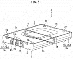
Fig. 3 is a perspective view illustrating a specific example of the battery module. -
Fig. 4 is an exploded perspective view of the battery module ofFig. 3 . -
Fig. 5 is a perspective view of a battery module stack composed of a plurality of battery modules ofFig. 3 stacked on top of each other. -
Fig. 6 is a perspective view illustrating a plurality of battery module stacks ofFig. 5 arranged side by side. -
Fig. 7 is an operation explanatory view illustrating a flow of high-temperature gas which is emitted from a battery in the battery module situated at the bottom of one of the battery module stacks. -
Fig. 8 is a cross-sectional view of a battery module having the same shape as that ofFig. 2 excepting that the side wall of the lower case is shorter in the up and down direction. -
Fig. 9 is a cross-sectional view of a battery module according to a second embodiment of the present invention, in which the sidewall of the lower case is inclined. -
Fig. 10 is a cross-sectional view of a battery module in which the sidewall of the lower case has a planar shape extending in the vertical direction. -
Fig. 11 is a cross-sectional view of a battery module having the same shape as that ofFig. 10 excepting that the side wall of the lower case is shorter in the up and down direction. -
Fig. 12 is a cross-sectional view of a battery module in which the sidewall of the lower case includes a lower vertical portion and an upper vertical portion. -
Fig. 13 is a perspective view illustrating a battery module with communicating portions partially formed. - Hereinafter, a description is given of embodiments of the present invention with reference to the drawings.
-
Fig. 1 is a simplified cross-sectional view of abattery pack 31, which includes plural (four inFig. 1 )battery modules 1 according to a first embodiment of the present invention. Thebattery modules 1 are stacked on top of each other in the up and down direction (in the vertical direction). Each of thebattery modules 1 has a rectangular shape in plan view and is a flat cuboid as a whole. - In each of the
battery modules 1, abattery 11 is accommodated in anaccommodation space 9 of acase 7 including alower case 3 and anupper case 5 as illustrated inFig. 2 . In other words, thebattery module 1 includes thecase 7 andbattery 11, and thecase 7 is composed of the lower andupper cases lower case 3 covers lower part of thebattery 11, and theupper case 5 covers upper part of thebattery 11. - The
battery 11 includes plural (four inFig. 2 )unit cells 13 stacked on top of each other. Theplural unit cells 13 are electrically connected in series or in parallel. Theunit cells 13 are used as a secondary battery for vehicles like lithium ion secondary batteries, for example. - Each of the
unit cells 13 is a so-called laminate battery, for example. Eachunit cell 13 includes a power generating element accommodated in a bag-shaped package together with an electrolyte. The power generating element includes positive and negative plates (electrode plates) which are stacked with a separator interposed therebetween. - The positive plate includes a collector made of aluminum foil, for example, and cathode active material layers formed on both surfaces of the collector. Each cathode active material layer includes a cathode active material composed of a lithium-transition metal composite oxide such as LiMn2O4, for example, a conductive agent, a binder, and the like.
- The negative plate includes a collector made of copper foil, for example, and anode active material layers formed on both surfaces of the collector. Each anode active material layers includes an anode active material, a conductive agent, a binder, and the like. Examples of the anode active material are hard carbon (non-graphitizable carbon materials), graphite carbon materials, and lithium-transition metal composite oxides.
- Each separator is made of polyolefin such as polyethylene or polypropylene, polyamide, or polyimide, for example.
- The electrolyte (electrolytic solution) contains an organic solvent, a supporting electrolyte, and the like. Examples of the organic solvent are cyclic carbonates such as propylene carbonate (PC) and ethylene carbonate (EC), chain carbonates such as dimethyl carbonate, and ethers such as tetrahydrofuran. The supporting salt is an inorganic acid anionic salt such as lithium salt (LiPF6) or an organic acid anionic salt such as LiCF3SO3.
- The package is made of laminate film including a metallic layer and polymer resin layers formed on both surfaces of the metallic layer, for example. The metallic layer is composed of metallic foil made of aluminum, stainless, nickel, copper, or the like, for example. The polymer resin layers are composed of thermally fused resin film made of polyethylene, polypropylene, modified polyethylene, modified polypropylene, ionomer, ethylene vinyl acetate, or the like. The package is formed into a bag by laying two sheets of laminate film described above on top of each other and welding the outer edges thereof. The package may be also formed into a bag by folding a sheet of laminate film and welding the outer edge thereof.
- When an abnormality, such as a short-circuit, occurs in any one of the
unit cells 13, gas could be generated within the package and increase the internal pressure of the package. The welded edges of the sheets of laminate film laid on each other are thereby separted, and the gas within the package is emitted to the outside. - The
lower case 3 of thecase 7 includes abottom wall portion 3a located in lower part of thebattery 11 andsidewall portions 3b extending upward from the outer limit of thebottom wall portion 3a. On the other hand, theupper case 5 includes atop wall portion 5a located in upper part of thebattery 11 andsidewall portions 5b extending downward from the outer limit of thetop wall portion 5a. - One of the
sidewall portions 3b of thelower case 3 is located outside of thecorresponding sidewall portion 5b of theupper case 5. To be specific, thesidewall portion 3b is situated outside of thecorresponding sidewall portion 5b (on the opposite side of thesidewall portion 5b from the accommodation space 9) and is spaced from thesidewall portion 5b. Moreover, an upper end 3b1 of thesidewall portion 3b is located above a lower end 5b1 of thecorresponding sidewall portion 5b of theupper case 5. In other words, part of thesidewall portion 3b of thelower case 3 overlaps part of thesidewall portion 5b of theupper case 5 in the horizontal direction (in the in-plane direction of the battery 11). Between thesidewall portion 3b andsidewall portion 5b, a communicatingportion 15 is formed, which enables theaccommodation space 9 within thecase 7 to communicate with the outside of thecase 7. In other words, thesidewall portions portions 15, through which theaccommodation space 9 within thecase 7 communicates with the outside of thecase 7. - One of the
sidewall portions 3b of thelower case 3 includes an inclined portion 3b2 in lower part and a vertical portion 3b3 in upper part. To be specific, the inclined portion 3b2 extends diagonally upward and outward from the outer limit of thebottom wall portion 3a, and the upper end of the inclined portion 3b2 continues to the vertical portion 3b3. The vertical portion 3b3 vertically extends upward from the upper end of the inclined portion 3b2. The above-described communicatingportion 15 is formed between an upper part of the vertical portion 3b3 and thecorresponding sidewall portion 5b of theupper case 5. - In the regions corresponding to two of the other three sides of the
rectangular case 7 in a plan view, thesidewall portions 3b of thelower case 3 and thecorresponding sidewall portions 5b of theupper case 5 are in the same positional relationship to form the same communicatingportions 15 as described above. The region corresponding to the remaining side is not provided with any communicatingportion 15 as a region provided with later-describedterminal portions 25 of the battery 11 (seeFig. 3 ). In other words, as illustrated inFigs. 3 and4 , in the region corresponding to the side provided with theterminal portions 25, theupper case 5 does not includes anysidewall portion 5b, and the upper end of the inner surface of thesidewall portion 3b of thelower case 3 , which has a planar shape extending in the vertical direction, is in contact with anedge 5c of theupper case 5. Thesidewall portion 3b of thelower case 3 is provided with openings 3bk allowing theterminal portions 25 to be exposed to the outside. - Next, a description is given of the specific shape and internal structure of the
battery module 1 with reference toFig. 4 . As illustrated inFig. 4 , thebattery 11, which is composed of theplural unit cells 13 laid on top of each other, is accommodated in thecase 7 with insulatingsheets battery 11. The insulatingsheets - The
battery 11 includesholder members plural unit cells 13. Theholder members holder member 21 is provided with theterminal portions 25 described above. - At both ends of each of the
holder members holes holes cylindrical sleeve 27 is inserted. The length of thesleeves 27 in the axial direction (in the height direction) is substantially equal to the thickness of theholder members upper case 5 is provided withbolt insertion holes 5h at the positions corresponding to therespective sleeves 27. In thelower case 3, not-illustrated nuts are attached to the positions corresponding to therespective sleeves 27. -
Bolts 29 are inserted into thebolt insertion holes 5h of theupper case 5 and thesleeves 27 and are fastened to the not-illustrated nuts of thelower case 3. Thebattery module 1 is thus completed. A plurality of thebattery modules 1 are prepared and stacked on top of each other in the up and down direction as illustrated inFig. 5 . The stackedbattery modules 1 are fixed to form thebattery module stack 31 as a battery pack. - In each
battery module 1, the lower ends of thesleeves 27 abut on the upper surface of thebottom wall portion 3a of thelower case 3 together with the lower surfaces of theholder members sleeves 27 abut on the lower surface of thetop wall portion 5a of theupper case 5 together with the upper surfaces of theholder members sleeves 27 in the axial direction, or the thickness of theholder members accommodation space 9 is formed between the lower andupper cases - To stack and fix the
plural battery modules 1 as illustrated inFig. 5 , thebattery module stack 31 may be accommodated and fixed in a battery pack case not illustrated or may be fixed separately using a fixing device. Moreover, thebolts 29 may be configured to have a length equal to the stacking thickness of thebattery module stack 31. Theplural battery modules 1 are fastened and fixed together with the bolts and nuts. - As illustrated in
Fig. 6 , a plurality of the battery module stacks 31 illustrated inFig. 5 may be prepared and arranged side by side. In this case, the plural battery module stacks 31 are placed on abase plate 33 to be fixed, and upper portions of the battery module stacks 31 adjacent to each other are fixed with fixingmembers 35. - Next, the operation is described.
- First, as illustrated in
Fig. 1 , the battery module stack 31 (battery pack) according to the first embodiment is composed of theplural battery modules 1 assembled. Accordingly, even when thebattery 11 within one of thebattery modules 1 generates high-temperature gas G due to abnormalities in the battery as illustrated inFig. 7 , heat of the gas G is prevented from influencing thebatteries 11 within theother battery modules 1. - The battery module stack 31 (battery pack) is composed of
plural battery modules 1 stacked in the up and down direction as illustrated inFig. 1 . Herein, it is assumed that there is an abnormality in thebattery 11 of thebattery module 1 located at the bottom, for example, and high-temperature gas G is generated from theabnormal battery 11 as illustrated inFig. 7 . InFig. 7 , two battery module stacks 31 are situated side by side as illustrated inFig. 6 . - According to the first embodiment, the communicating
portions 15, which enable communication between theaccommodation space 9 within thecase 7 and the outside of thecase 7, are provided between thesidewall portions 3b of thelower case 3 and thecorresponding sidewall portions 5b of theupper case 5. The high-temperature gas G generated from thebattery 11 at the bottom is discharged to the outside of thecase 7 through the communicatingportions 15. In the region provided with theterminal portions 25 illustrated inFig. 4 , the high-temperature gas G is discharged mainly through upper space of the openings 3bk above theterminal portions 25 and the amount thereof is very small. The upper space of the opening portions 3bk above theterminal portions 25 may be sealed by a sealing member. This can further reduce the discharge of the high-temperature gas G to the outside. - The high-temperature gas G discharged through the communicating
portions 15 to the outside of thecase 7 rises along the outer wall of the correspondingbattery module stack 31. In the first embodiment, the upper ends 3b1 of thesidewall portions 3b of thelower case 3 are located above the corresponding lower ends 5b1 of thesidewall portions 5b of theupper case 5, and thesidewall portions 3b of thelower case 3 are situated outside of thecorresponding sidewall portions 5b of the upper case 5 (in the opposite side of thesidewall portions 5b from the accommodation space 9) so as to be spaced from therespective sidewall portions 5b. - Accordingly, in the process where high-temperature gas G flows along the outer wall of the
battery module stack 31, the high-temperature gas G mainly flows along thesidewall portions 3b of thelower case 3 as illustrated inFig. 7 . In eachbattery modules 1 located above theabnormal battery module 1, heat of the high-temperature gas G is less likely to be transmitted to thesidewall portion 5b of theupper case 5, and moreover the high-temperature gas G is less likely to enter theaccommodation space 9 of thecase 7 through the communicatingportion 15. Accordingly, thebattery modules 1 located above theabnormal battery module 1 are less likely to be influenced by heat of the high-temperature gas G, so that degradation of thebatteries 11 are prevented. - Also in the other
battery module stack 31 arranged adjacent to thebattery module stack 31 including theabnormal battery module 1, heat of the generated high-temperature gas G is less likely to be transmitted to thesidewall portions 5b of theupper case 5. Moreover, in the otherbattery module stack 31 arranged adjacent thereto, the high-temperature gas G is less likely to enter thecase 7 through the communicatingportions 15. Accordingly, even when the battery module stacks 31 are placed side by side in the lateral direction (in the horizontal direction), eachbattery module 1 is less influenced by high-temperature gas G from thebattery modules 1 adjacent thereto in the lateral direction (in the horizontal direction). - In the lower part of the
sidewall portions 3b of thelower case 3, the inclined portions 3b2 extend upward and outward to be widened. Accordingly, high-temperature gas G generated within thecase 7 is guided by the inclined portions 3b2 to easily flow to the communicatingportions 15 between thesidewall portions 3b of thelower case 3 and thesidewall portions 5b of theupper case 5, thus further ensuring the discharge of high-temperature gas G to the outside of thecase 7. - Each inclined portion 3b2 described above has a planar shape but may be curved and protruded outward so that the inner surface has a profile concave upward. When each inclined portion 3b2 has a curved face so that the inner surface is concave outward, high-temperature gas G flows to the communicating
portions 15 more easily. - In the example illustrated in
Figs. 1 and 2 , the upper ends 3b1 of thesidewall portions 3b of thelower case 3 are located at the substantially same position in the up and down direction as thetop wall portion 5a of theupper case 5. On the other hand, the upper ends 3b1 of thesidewall portions 3b may be situated below thetop wall portion 5a of theupper case 5 like abattery module 1A illustrated inFig. 8 if the upper ends 3b1 of thesidewall portions 3b are situated above the lower ends 5b1 of thesidewall portions 5b of theupper case 5. However, the high-temperature gas G generated from one of thebattery modules 1 can be more definitely prevented from entering thecases 7 of thebattery modules 1 located above thebattery module 1 emitting the high-temperature gas G when the upper ends 3b1 of thesidewall portions 3b are extended higher as illustrated inFigs. 1 and 2 than those inFig. 8 . -
Fig. 9 illustrates abattery module 1B according to a second embodiment of the present invention. In thebattery module 1B, eachsidewall portion 3b of thelower case 3 is inclined so that upper part thereof is situated farther outward from theaccommodation space 9 than lower part thereof. To be specific, eachsidewall portion 3b of thelower case 3 is separted from the correspondingsidewall portion 5b of theupper case 5 in the horizontal direction so that the upper end 3b1 is situated farther outward from thesidewall portion 5b than a lower end 3b4, which connects to thebottom wall 3a of thelower case 3. Thesidewall portions 3b extend upward from the lower end 3b4 and incline so as to be widened outward. In this case, the channel cross-sectional area of the communicating portion 14 between eachsidewall portion 3b of thelower case 3 and thecorresponding sidewall portion 5b of theupper case 5 gradually increases from the lower part toward the upper part. - As described above, in the
battery module 1B of the second embodiment, thesidewall portions 3b of thelower case 3 incline so that the upper ends 3b1 as the upper part are situated outside of the corresponding lower ends 3b4 as the lower part with respect to theaccommodation space 9, and the channel cross-sectional area of the communicatingportions 15 increases toward the upper part. Accordingly, high-temperature gas G generated from thebattery 11 within thebattery module 1B can be more surely emitted out of thecase 7 along theinclined sidewall portions 3b. In anotherbattery module 1B situated above theabnormal battery module 1, heat of the high-temperature gas G is less likely to be transmitted to thesidewall portions 5b of theupper case 5. Accordingly, it is therefore possible to prevent degradation of thebatteries 11 within thebattery modules 1B more definitely. Eachsidewall portion 3b inFig. 9 has a planar shape but may have a curved face with the inner surface being concave upward. - Moreover, each
sidewall portion 3b of thelower case 3 may be shaped as illustrated inbattery modules 1C to 1E ofFigs. 10 to 12 . In thebattery modules Figs. 10 and 11 , thesidewall portions 3b of thelower case 3 have a planer shape extending in the vertical direction. InFig. 10 , the upper ends 3b1 of thesidewall portions 3b are situated at the substantially same position in the up and down direction as thetop wall portion 5a of theupper case 5a. InFig. 11 , upper ends 3b1 of thesidewall portions 3b are situated between thetop wall portion 5a of theupper case 5 and the corresponding lower end 5b1 of thesidewall portion 5b. - In the example of
Fig. 10 , the overlapping area between eachsidewall portion 3b of thelower case 3 and thecorresponding sidewall portion 5b of theupper case 5 in the horizontal direction is larger than that in the example ofFig. 11 . Accordingly, the effect of preventing heat of the high-temperature gas G from being transmitted to thesidewall portions 5b of theupper case 5 and the effect of preventing the high-temperature gas G from entering thecase 7 are higher in the example ofFig. 10 than in the example ofFig. 11 . - In the
battery module 1E illustrated inFig. 12 , eachsidewall portion 3b of thelower case 3 includes a lower vertical portion 3b5 situated in lower part, an upper vertical portion 3b6 situated in upper part, and an inclined portion 3b7 situated between the vertical portions 3b5 and 3b6. The upper vertical portion 3b6 is situated outside of the lower vertical portion 3b5 and partially overlaps the correspondingsidewall portion 5b of theupper case 5 in the horizontal direction. To be specific, thesidewall portion 3b is integrally composed of the lower vertical portion 3b5, which is provided in the lower side and vertically extended, the inclined portion 3b7, which is extended upward and outward from the upper end of the lower vertical portion 3b5, and the upper vertical portion 3b6, which is extended in the vertical direction from the upper end of the inclined portion 3b7. The inclined portion 3b7 may have a shape curved and protruded outward so that the inner surface thereof is concave upward, instead of the planer shape thereof. - In the example of the
battery module 1E ofFig. 12 , the high-temperature gas G generated within thecase 7 can be easily emitted to the outside along the inclined portion 3b7 or the curved surface replaced for the inclined portion 3b7. - Hereinabove, the embodiments of the present invention is described. However, these embodiments are just examples illustrated for easy understanding of the present invention, and the present invention is not limited to these embodiments. The technical scope of the present invention includes not only the specific technical matters disclosed in the embodiments but also various modifications, changes, and alternative techniques easily derived from the embodiments.
- The
sidewall portions 3b of thelower case 3 may have various shapes in addition to the examples described above, for example. - As described in
Figs. 3 and5 , in the above-described embodiments, the communicatingportions 15 are formed at the respective regions corresponding to three sides around therectangular case 7. However, the battery module maybe properly changed so as to include one of the communicatingportions 15 in only one side, for example. In the above-described embodiment, each communicatingportion 15 is continuously provided for one of the four sides of therectangular case 7. However, like abattery module 1F illustrated inFig. 13 , for example, the communicatingportions 15 may be partially provided for each side of therectangular case 7. In the case ofFig. 13 , three partial communicatingportions 15 are formed, but the number thereof is not limited. Moreover, thecase 7 accommodatesplural unit cells 13 but may be configured to accommodate oneunit cell 13. - This application is based upon and claims the benefit of priority to
Japanese Patent Application No. 2013-210704 filed on October 8, 2013 - With the battery pack according to the present invention, even when a battery within one of battery modules generates high-temperature gas due to abnormalities in the battery, heat of the high-temperature gas is prevented from influencing a battery within another battery module.
-
- 1, 1A, 1B, 1C, 1D, 1E, 1F
- BATTERY MODULE
- 3
- LOWER CASE
- 3a
- BOTTOM WALL PORTION OF LOWER CASE
- 3b
- SIDEWALL PORTION OF LOWER CASE
- 3b1
- UPPER END OF SIDEWALL PORTION OF LOWER CASE
- 5
- UPPER CASE
- 5a
- BOTTOM WALL PORTION OF UPPER CASE
- 5b
- SIDEWALL PORTION OF UPPER CASE
- 5b1
- LOWER END OF SIDEWALL PORTION OF UPPER CASE
- 7
- CASE OF BATTERY MODULE
- 9
- ACCOMMODATION SPACE IN CASE
- 11
- BATTERY
- 13
- UNIT CELL
- 15
- COMMUNICATING PORTION
- 31
- battery module stack (battery pack)
Claims (5)
- A battery pack, comprising:a plurality of battery modules, whereineach of the plurality of battery modules includes a battery and a case accommodating the battery,the case includes a lower case covering lower part of the battery within the case and an upper case covering upper part,between the lower and upper cases, an accommodation space accommodating the battery is formed,the lower case includes a bottom wall portion situated under the battery and a sidewall portion extending upward from the outer limit of the bottom wall portion,the upper case includes a top wall portion situated over the battery and a sidewall portion extending downward from the outer limit of the top wall portion,the sidewall portion of the lower case is situated on the outside, which is the opposite side of the sidewall portion of the upper case from the accommodation space, and is spaced from the sidewall portion of the upper case and the upper end of the sidewall portion of the lower case is situated above the lower end of the sidewall portion of the upper case, andbetween the sidewall portions of the lower and upper cases, a communicating portion enabling communication between the accommodation space and the outside of the case is provided.
- The battery pack according to claim 1, wherein the plurality of battery modules are stacked on top of each other in the up and down direction.
- The battery pack according to claim 1 or 2, wherein the sidewall portion of the lower case is inclined so that upper part thereof is situated farther outward from the accommodation space than lower part thereof.
- The battery pack according to any one of claims 1 to 3, wherein the inner surface of the sidewall portion of the lower case is concave upward.
- The battery pack according to any one of claims 1 to 4, wherein the battery is composed of a plurality of unit cells, and
each unit cell is a laminate cell which includes a power generating element and an electrolyte accommodated within a bag-shaped package, the power generating element including a positive plate, a negative plate, and a separator which are stacked on top of each other.
Applications Claiming Priority (2)
| Application Number | Priority Date | Filing Date | Title |
|---|---|---|---|
| JP2013210704 | 2013-10-08 | ||
| PCT/JP2014/075859 WO2015053119A1 (en) | 2013-10-08 | 2014-09-29 | Battery pack |
Publications (3)
| Publication Number | Publication Date |
|---|---|
| EP3057155A1 true EP3057155A1 (en) | 2016-08-17 |
| EP3057155A4 EP3057155A4 (en) | 2016-11-16 |
| EP3057155B1 EP3057155B1 (en) | 2017-06-21 |
Family
ID=52812938
Family Applications (1)
| Application Number | Title | Priority Date | Filing Date |
|---|---|---|---|
| EP14852362.4A Active EP3057155B1 (en) | 2013-10-08 | 2014-09-29 | Battery pack |
Country Status (6)
| Country | Link |
|---|---|
| US (1) | US10096804B2 (en) |
| EP (1) | EP3057155B1 (en) |
| JP (1) | JP6090469B2 (en) |
| KR (1) | KR101742929B1 (en) |
| CN (1) | CN105637672B (en) |
| WO (1) | WO2015053119A1 (en) |
Families Citing this family (12)
| Publication number | Priority date | Publication date | Assignee | Title |
|---|---|---|---|---|
| US10707531B1 (en) | 2016-09-27 | 2020-07-07 | New Dominion Enterprises Inc. | All-inorganic solvents for electrolytes |
| KR102555500B1 (en) | 2017-12-18 | 2023-07-12 | 삼성에스디아이 주식회사 | Electrode assembly |
| KR102455471B1 (en) * | 2019-02-18 | 2022-10-14 | 주식회사 엘지에너지솔루션 | Battery cell, battery module comprising the battery cell, battery rack comprising the battery module and energy storage system comprising the battery rack |
| CN109980150B (en) * | 2019-04-02 | 2022-03-22 | 蜂巢能源科技有限公司 | Battery pack and vehicle |
| JP7462476B2 (en) * | 2020-06-01 | 2024-04-05 | 本田技研工業株式会社 | Secondary battery |
| JP7616736B2 (en) * | 2021-03-31 | 2025-01-17 | 住友建機株式会社 | Excavator |
| US20230033505A1 (en) * | 2021-07-28 | 2023-02-02 | Rivian Ip Holdings, Llc | Battery module thermal isolation |
| EP4345999B1 (en) * | 2021-12-24 | 2026-02-11 | LG Energy Solution, Ltd. | Battery module having improved safety and assemblability |
| ES3064737T3 (en) * | 2022-07-20 | 2026-04-28 | Lg Energy Solution Ltd | Battery pack, battery module, and vehicle including same |
| WO2024048985A1 (en) * | 2022-08-31 | 2024-03-07 | 주식회사 엘지에너지솔루션 | Battery pack, battery module and vehicle comprising same |
| EP4704240A1 (en) * | 2023-04-28 | 2026-03-04 | Panasonic Intellectual Property Management Co., Ltd. | Power supply device |
| WO2024224906A1 (en) * | 2023-04-28 | 2024-10-31 | パナソニックIpマネジメント株式会社 | Power supply device |
Family Cites Families (12)
| Publication number | Priority date | Publication date | Assignee | Title |
|---|---|---|---|---|
| US2416576A (en) * | 1943-10-20 | 1947-02-25 | Olin Ind Inc | Flat type dry battery |
| JP2001084974A (en) * | 1999-09-13 | 2001-03-30 | Japan Storage Battery Co Ltd | Battery pack |
| KR100863730B1 (en) * | 2006-09-04 | 2008-10-16 | 주식회사 엘지화학 | Battery cell having a fine groove formed on the outer surface and a battery pack comprising the same |
| JP2009021067A (en) * | 2007-07-11 | 2009-01-29 | Fuji Heavy Ind Ltd | Power storage assembly |
| JP2009146812A (en) * | 2007-12-17 | 2009-07-02 | Nissan Motor Co Ltd | Battery case and battery pack |
| CA2761758C (en) * | 2009-05-11 | 2015-03-24 | Magna Steyr Fahrzeugtechnik Ag & Co Kg | Battery unit |
| JP5481982B2 (en) * | 2009-07-17 | 2014-04-23 | 日産自動車株式会社 | Battery module |
| JP5479947B2 (en) | 2010-03-01 | 2014-04-23 | 大和製罐株式会社 | Battery case |
| JP5589737B2 (en) | 2010-10-07 | 2014-09-17 | トヨタ自動車株式会社 | Battery and manufacturing method thereof |
| JP2013012458A (en) | 2011-05-27 | 2013-01-17 | Sony Corp | Battery unit, battery module, power storage system, electronic device, power system, and electric vehicle |
| JP2013186995A (en) | 2012-03-07 | 2013-09-19 | Nissan Motor Co Ltd | Battery pack |
| JP5482828B2 (en) * | 2012-06-21 | 2014-05-07 | 日産自動車株式会社 | Battery module |
-
2014
- 2014-09-29 US US15/028,315 patent/US10096804B2/en active Active
- 2014-09-29 KR KR1020167008635A patent/KR101742929B1/en active Active
- 2014-09-29 EP EP14852362.4A patent/EP3057155B1/en active Active
- 2014-09-29 CN CN201480055741.8A patent/CN105637672B/en active Active
- 2014-09-29 WO PCT/JP2014/075859 patent/WO2015053119A1/en not_active Ceased
- 2014-09-29 JP JP2015541525A patent/JP6090469B2/en active Active
Also Published As
| Publication number | Publication date |
|---|---|
| CN105637672B (en) | 2017-07-25 |
| KR20160050067A (en) | 2016-05-10 |
| CN105637672A (en) | 2016-06-01 |
| JP6090469B2 (en) | 2017-03-08 |
| JPWO2015053119A1 (en) | 2017-03-09 |
| US10096804B2 (en) | 2018-10-09 |
| KR101742929B1 (en) | 2017-06-01 |
| EP3057155A4 (en) | 2016-11-16 |
| WO2015053119A1 (en) | 2015-04-16 |
| EP3057155B1 (en) | 2017-06-21 |
| US20160248058A1 (en) | 2016-08-25 |
Similar Documents
| Publication | Publication Date | Title |
|---|---|---|
| EP3057155B1 (en) | Battery pack | |
| US9537121B2 (en) | Secondary battery and secondary battery pack having a flexible collecting tab extending through a cap plate | |
| US9548475B2 (en) | Battery cell of irregular structure and battery module employed with the same | |
| US8043743B2 (en) | Pouch type secondary battery with improved safety | |
| KR101222247B1 (en) | Secondary battery | |
| KR101243546B1 (en) | Rechargeable battery and battery pack having the same | |
| US9543612B2 (en) | Rechargeable battery | |
| KR102288544B1 (en) | Secondary Battery And Fabricating Method Thereof | |
| KR101222369B1 (en) | Battery and battery pack comprising the same | |
| EP3518305B1 (en) | Secondary battery | |
| US20120171525A1 (en) | Secondary battery | |
| US20260100475A1 (en) | Battery pack and device including the same | |
| KR20130012539A (en) | Secondary battery | |
| KR102113155B1 (en) | Battery module and battery pack | |
| US12512548B2 (en) | Battery pack and device including the same | |
| US9012059B2 (en) | Secondary battery | |
| CN108242512A (en) | Battery pack | |
| US20210384593A1 (en) | Secondary battery | |
| US8778526B2 (en) | Secondary battery | |
| EP4517937A1 (en) | Secondary battery | |
| KR20240168135A (en) | Battery pack | |
| KR20120081385A (en) | Electrode assembly and secondary battery using same |
Legal Events
| Date | Code | Title | Description |
|---|---|---|---|
| PUAI | Public reference made under article 153(3) epc to a published international application that has entered the european phase |
Free format text: ORIGINAL CODE: 0009012 |
|
| 17P | Request for examination filed |
Effective date: 20160414 |
|
| AK | Designated contracting states |
Kind code of ref document: A1 Designated state(s): AL AT BE BG CH CY CZ DE DK EE ES FI FR GB GR HR HU IE IS IT LI LT LU LV MC MK MT NL NO PL PT RO RS SE SI SK SM TR |
|
| AX | Request for extension of the european patent |
Extension state: BA ME |
|
| A4 | Supplementary search report drawn up and despatched |
Effective date: 20161013 |
|
| RIC1 | Information provided on ipc code assigned before grant |
Ipc: H01M 2/10 20060101AFI20161007BHEP Ipc: H01M 2/02 20060101ALI20161007BHEP Ipc: H01M 2/12 20060101ALI20161007BHEP |
|
| DAX | Request for extension of the european patent (deleted) | ||
| GRAP | Despatch of communication of intention to grant a patent |
Free format text: ORIGINAL CODE: EPIDOSNIGR1 |
|
| RIC1 | Information provided on ipc code assigned before grant |
Ipc: H01M 2/02 20060101ALI20170117BHEP Ipc: H01M 2/10 20060101AFI20170117BHEP Ipc: H01M 2/12 20060101ALI20170117BHEP |
|
| INTG | Intention to grant announced |
Effective date: 20170215 |
|
| GRAS | Grant fee paid |
Free format text: ORIGINAL CODE: EPIDOSNIGR3 |
|
| GRAA | (expected) grant |
Free format text: ORIGINAL CODE: 0009210 |
|
| AK | Designated contracting states |
Kind code of ref document: B1 Designated state(s): AL AT BE BG CH CY CZ DE DK EE ES FI FR GB GR HR HU IE IS IT LI LT LU LV MC MK MT NL NO PL PT RO RS SE SI SK SM TR |
|
| REG | Reference to a national code |
Ref country code: GB Ref legal event code: FG4D |
|
| REG | Reference to a national code |
Ref country code: CH Ref legal event code: EP |
|
| REG | Reference to a national code |
Ref country code: IE Ref legal event code: FG4D |
|
| REG | Reference to a national code |
Ref country code: AT Ref legal event code: REF Ref document number: 903663 Country of ref document: AT Kind code of ref document: T Effective date: 20170715 |
|
| REG | Reference to a national code |
Ref country code: DE Ref legal event code: R096 Ref document number: 602014011099 Country of ref document: DE |
|
| REG | Reference to a national code |
Ref country code: FR Ref legal event code: PLFP Year of fee payment: 4 |
|
| REG | Reference to a national code |
Ref country code: NL Ref legal event code: MP Effective date: 20170621 |
|
| PG25 | Lapsed in a contracting state [announced via postgrant information from national office to epo] |
Ref country code: GR Free format text: LAPSE BECAUSE OF FAILURE TO SUBMIT A TRANSLATION OF THE DESCRIPTION OR TO PAY THE FEE WITHIN THE PRESCRIBED TIME-LIMIT Effective date: 20170922 Ref country code: NO Free format text: LAPSE BECAUSE OF FAILURE TO SUBMIT A TRANSLATION OF THE DESCRIPTION OR TO PAY THE FEE WITHIN THE PRESCRIBED TIME-LIMIT Effective date: 20170921 Ref country code: LT Free format text: LAPSE BECAUSE OF FAILURE TO SUBMIT A TRANSLATION OF THE DESCRIPTION OR TO PAY THE FEE WITHIN THE PRESCRIBED TIME-LIMIT Effective date: 20170621 Ref country code: HR Free format text: LAPSE BECAUSE OF FAILURE TO SUBMIT A TRANSLATION OF THE DESCRIPTION OR TO PAY THE FEE WITHIN THE PRESCRIBED TIME-LIMIT Effective date: 20170621 Ref country code: FI Free format text: LAPSE BECAUSE OF FAILURE TO SUBMIT A TRANSLATION OF THE DESCRIPTION OR TO PAY THE FEE WITHIN THE PRESCRIBED TIME-LIMIT Effective date: 20170621 |
|
| REG | Reference to a national code |
Ref country code: LT Ref legal event code: MG4D |
|
| REG | Reference to a national code |
Ref country code: AT Ref legal event code: MK05 Ref document number: 903663 Country of ref document: AT Kind code of ref document: T Effective date: 20170621 |
|
| PG25 | Lapsed in a contracting state [announced via postgrant information from national office to epo] |
Ref country code: BG Free format text: LAPSE BECAUSE OF FAILURE TO SUBMIT A TRANSLATION OF THE DESCRIPTION OR TO PAY THE FEE WITHIN THE PRESCRIBED TIME-LIMIT Effective date: 20170921 Ref country code: NL Free format text: LAPSE BECAUSE OF FAILURE TO SUBMIT A TRANSLATION OF THE DESCRIPTION OR TO PAY THE FEE WITHIN THE PRESCRIBED TIME-LIMIT Effective date: 20170621 Ref country code: SE Free format text: LAPSE BECAUSE OF FAILURE TO SUBMIT A TRANSLATION OF THE DESCRIPTION OR TO PAY THE FEE WITHIN THE PRESCRIBED TIME-LIMIT Effective date: 20170621 Ref country code: LV Free format text: LAPSE BECAUSE OF FAILURE TO SUBMIT A TRANSLATION OF THE DESCRIPTION OR TO PAY THE FEE WITHIN THE PRESCRIBED TIME-LIMIT Effective date: 20170621 Ref country code: RS Free format text: LAPSE BECAUSE OF FAILURE TO SUBMIT A TRANSLATION OF THE DESCRIPTION OR TO PAY THE FEE WITHIN THE PRESCRIBED TIME-LIMIT Effective date: 20170621 |
|
| PG25 | Lapsed in a contracting state [announced via postgrant information from national office to epo] |
Ref country code: EE Free format text: LAPSE BECAUSE OF FAILURE TO SUBMIT A TRANSLATION OF THE DESCRIPTION OR TO PAY THE FEE WITHIN THE PRESCRIBED TIME-LIMIT Effective date: 20170621 Ref country code: RO Free format text: LAPSE BECAUSE OF FAILURE TO SUBMIT A TRANSLATION OF THE DESCRIPTION OR TO PAY THE FEE WITHIN THE PRESCRIBED TIME-LIMIT Effective date: 20170621 Ref country code: CZ Free format text: LAPSE BECAUSE OF FAILURE TO SUBMIT A TRANSLATION OF THE DESCRIPTION OR TO PAY THE FEE WITHIN THE PRESCRIBED TIME-LIMIT Effective date: 20170621 Ref country code: SK Free format text: LAPSE BECAUSE OF FAILURE TO SUBMIT A TRANSLATION OF THE DESCRIPTION OR TO PAY THE FEE WITHIN THE PRESCRIBED TIME-LIMIT Effective date: 20170621 Ref country code: AT Free format text: LAPSE BECAUSE OF FAILURE TO SUBMIT A TRANSLATION OF THE DESCRIPTION OR TO PAY THE FEE WITHIN THE PRESCRIBED TIME-LIMIT Effective date: 20170621 |
|
| PG25 | Lapsed in a contracting state [announced via postgrant information from national office to epo] |
Ref country code: IT Free format text: LAPSE BECAUSE OF FAILURE TO SUBMIT A TRANSLATION OF THE DESCRIPTION OR TO PAY THE FEE WITHIN THE PRESCRIBED TIME-LIMIT Effective date: 20170621 Ref country code: IS Free format text: LAPSE BECAUSE OF FAILURE TO SUBMIT A TRANSLATION OF THE DESCRIPTION OR TO PAY THE FEE WITHIN THE PRESCRIBED TIME-LIMIT Effective date: 20171021 Ref country code: ES Free format text: LAPSE BECAUSE OF FAILURE TO SUBMIT A TRANSLATION OF THE DESCRIPTION OR TO PAY THE FEE WITHIN THE PRESCRIBED TIME-LIMIT Effective date: 20170621 Ref country code: SM Free format text: LAPSE BECAUSE OF FAILURE TO SUBMIT A TRANSLATION OF THE DESCRIPTION OR TO PAY THE FEE WITHIN THE PRESCRIBED TIME-LIMIT Effective date: 20170621 Ref country code: PL Free format text: LAPSE BECAUSE OF FAILURE TO SUBMIT A TRANSLATION OF THE DESCRIPTION OR TO PAY THE FEE WITHIN THE PRESCRIBED TIME-LIMIT Effective date: 20170621 |
|
| REG | Reference to a national code |
Ref country code: DE Ref legal event code: R097 Ref document number: 602014011099 Country of ref document: DE |
|
| PLBE | No opposition filed within time limit |
Free format text: ORIGINAL CODE: 0009261 |
|
| STAA | Information on the status of an ep patent application or granted ep patent |
Free format text: STATUS: NO OPPOSITION FILED WITHIN TIME LIMIT |
|
| PG25 | Lapsed in a contracting state [announced via postgrant information from national office to epo] |
Ref country code: DK Free format text: LAPSE BECAUSE OF FAILURE TO SUBMIT A TRANSLATION OF THE DESCRIPTION OR TO PAY THE FEE WITHIN THE PRESCRIBED TIME-LIMIT Effective date: 20170621 |
|
| REG | Reference to a national code |
Ref country code: CH Ref legal event code: PL |
|
| 26N | No opposition filed |
Effective date: 20180322 |
|
| PG25 | Lapsed in a contracting state [announced via postgrant information from national office to epo] |
Ref country code: MC Free format text: LAPSE BECAUSE OF FAILURE TO SUBMIT A TRANSLATION OF THE DESCRIPTION OR TO PAY THE FEE WITHIN THE PRESCRIBED TIME-LIMIT Effective date: 20170621 |
|
| REG | Reference to a national code |
Ref country code: IE Ref legal event code: MM4A |
|
| REG | Reference to a national code |
Ref country code: BE Ref legal event code: MM Effective date: 20170930 |
|
| PG25 | Lapsed in a contracting state [announced via postgrant information from national office to epo] |
Ref country code: LU Free format text: LAPSE BECAUSE OF NON-PAYMENT OF DUE FEES Effective date: 20170929 |
|
| PG25 | Lapsed in a contracting state [announced via postgrant information from national office to epo] |
Ref country code: IE Free format text: LAPSE BECAUSE OF NON-PAYMENT OF DUE FEES Effective date: 20170929 Ref country code: LI Free format text: LAPSE BECAUSE OF NON-PAYMENT OF DUE FEES Effective date: 20170930 Ref country code: CH Free format text: LAPSE BECAUSE OF NON-PAYMENT OF DUE FEES Effective date: 20170930 |
|
| REG | Reference to a national code |
Ref country code: FR Ref legal event code: PLFP Year of fee payment: 5 |
|
| PG25 | Lapsed in a contracting state [announced via postgrant information from national office to epo] |
Ref country code: SI Free format text: LAPSE BECAUSE OF FAILURE TO SUBMIT A TRANSLATION OF THE DESCRIPTION OR TO PAY THE FEE WITHIN THE PRESCRIBED TIME-LIMIT Effective date: 20170621 Ref country code: BE Free format text: LAPSE BECAUSE OF NON-PAYMENT OF DUE FEES Effective date: 20170930 |
|
| PG25 | Lapsed in a contracting state [announced via postgrant information from national office to epo] |
Ref country code: MT Free format text: LAPSE BECAUSE OF NON-PAYMENT OF DUE FEES Effective date: 20170929 |
|
| PG25 | Lapsed in a contracting state [announced via postgrant information from national office to epo] |
Ref country code: HU Free format text: LAPSE BECAUSE OF FAILURE TO SUBMIT A TRANSLATION OF THE DESCRIPTION OR TO PAY THE FEE WITHIN THE PRESCRIBED TIME-LIMIT; INVALID AB INITIO Effective date: 20140929 |
|
| REG | Reference to a national code |
Ref country code: DE Ref legal event code: R082 Ref document number: 602014011099 Country of ref document: DE Representative=s name: GRUENECKER PATENT- UND RECHTSANWAELTE PARTG MB, DE Ref country code: DE Ref legal event code: R081 Ref document number: 602014011099 Country of ref document: DE Owner name: ENVISION AESC JAPAN LTD., ZAMA-SHI, JP Free format text: FORMER OWNER: NISSAN MOTOR CO., LTD., YOKOHAMA-SHI, KANAGAWA-KEN, JP |
|
| REG | Reference to a national code |
Ref country code: GB Ref legal event code: 732E Free format text: REGISTERED BETWEEN 20190919 AND 20190925 |
|
| PG25 | Lapsed in a contracting state [announced via postgrant information from national office to epo] |
Ref country code: CY Free format text: LAPSE BECAUSE OF FAILURE TO SUBMIT A TRANSLATION OF THE DESCRIPTION OR TO PAY THE FEE WITHIN THE PRESCRIBED TIME-LIMIT Effective date: 20170621 |
|
| PG25 | Lapsed in a contracting state [announced via postgrant information from national office to epo] |
Ref country code: MK Free format text: LAPSE BECAUSE OF FAILURE TO SUBMIT A TRANSLATION OF THE DESCRIPTION OR TO PAY THE FEE WITHIN THE PRESCRIBED TIME-LIMIT Effective date: 20170621 |
|
| PG25 | Lapsed in a contracting state [announced via postgrant information from national office to epo] |
Ref country code: TR Free format text: LAPSE BECAUSE OF FAILURE TO SUBMIT A TRANSLATION OF THE DESCRIPTION OR TO PAY THE FEE WITHIN THE PRESCRIBED TIME-LIMIT Effective date: 20170621 |
|
| PG25 | Lapsed in a contracting state [announced via postgrant information from national office to epo] |
Ref country code: PT Free format text: LAPSE BECAUSE OF FAILURE TO SUBMIT A TRANSLATION OF THE DESCRIPTION OR TO PAY THE FEE WITHIN THE PRESCRIBED TIME-LIMIT Effective date: 20170621 |
|
| PG25 | Lapsed in a contracting state [announced via postgrant information from national office to epo] |
Ref country code: AL Free format text: LAPSE BECAUSE OF FAILURE TO SUBMIT A TRANSLATION OF THE DESCRIPTION OR TO PAY THE FEE WITHIN THE PRESCRIBED TIME-LIMIT Effective date: 20170621 |
|
| REG | Reference to a national code |
Ref country code: DE Ref legal event code: R079 Ref document number: 602014011099 Country of ref document: DE Free format text: PREVIOUS MAIN CLASS: H01M0002100000 Ipc: H01M0050200000 |
|
| P01 | Opt-out of the competence of the unified patent court (upc) registered |
Effective date: 20230330 |
|
| PGFP | Annual fee paid to national office [announced via postgrant information from national office to epo] |
Ref country code: DE Payment date: 20250805 Year of fee payment: 12 |
|
| PGFP | Annual fee paid to national office [announced via postgrant information from national office to epo] |
Ref country code: GB Payment date: 20250807 Year of fee payment: 12 |
|
| PGFP | Annual fee paid to national office [announced via postgrant information from national office to epo] |
Ref country code: FR Payment date: 20250808 Year of fee payment: 12 |