EP3057154A1 - Battery holder - Google Patents
Battery holder Download PDFInfo
- Publication number
- EP3057154A1 EP3057154A1 EP14851961.4A EP14851961A EP3057154A1 EP 3057154 A1 EP3057154 A1 EP 3057154A1 EP 14851961 A EP14851961 A EP 14851961A EP 3057154 A1 EP3057154 A1 EP 3057154A1
- Authority
- EP
- European Patent Office
- Prior art keywords
- battery
- electrode contact
- contact portion
- base
- batteries
- Prior art date
- Legal status (The legal status is an assumption and is not a legal conclusion. Google has not performed a legal analysis and makes no representation as to the accuracy of the status listed.)
- Granted
Links
Images


Classifications
-
- H—ELECTRICITY
- H01—ELECTRIC ELEMENTS
- H01M—PROCESSES OR MEANS, e.g. BATTERIES, FOR THE DIRECT CONVERSION OF CHEMICAL ENERGY INTO ELECTRICAL ENERGY
- H01M50/00—Constructional details or processes of manufacture of the non-active parts of electrochemical cells other than fuel cells, e.g. hybrid cells
- H01M50/20—Mountings; Secondary casings or frames; Racks, modules or packs; Suspension devices; Shock absorbers; Transport or carrying devices; Holders
- H01M50/204—Racks, modules or packs for multiple batteries or multiple cells
- H01M50/207—Racks, modules or packs for multiple batteries or multiple cells characterised by their shape
- H01M50/213—Racks, modules or packs for multiple batteries or multiple cells characterised by their shape adapted for cells having curved cross-section, e.g. round or elliptic
-
- Y—GENERAL TAGGING OF NEW TECHNOLOGICAL DEVELOPMENTS; GENERAL TAGGING OF CROSS-SECTIONAL TECHNOLOGIES SPANNING OVER SEVERAL SECTIONS OF THE IPC; TECHNICAL SUBJECTS COVERED BY FORMER USPC CROSS-REFERENCE ART COLLECTIONS [XRACs] AND DIGESTS
- Y02—TECHNOLOGIES OR APPLICATIONS FOR MITIGATION OR ADAPTATION AGAINST CLIMATE CHANGE
- Y02E—REDUCTION OF GREENHOUSE GAS [GHG] EMISSIONS, RELATED TO ENERGY GENERATION, TRANSMISSION OR DISTRIBUTION
- Y02E60/00—Enabling technologies; Technologies with a potential or indirect contribution to GHG emissions mitigation
- Y02E60/10—Energy storage using batteries
Definitions
- the present invention relates to a battery holder, and in particular to an electrode structure thereof.
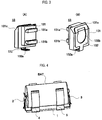
- Fig. 4 is a configuration explanatory view showing an example of a battery holder which has been conventionally used, in which the battery holder has a leaf spring-type electrode structure.
- a base plate 1 is formed in a rectangular shape having a long side with a length nearly equal to that of a battery BAT to be held thereon, and a positive electrode contact portion 2 made of a leaf spring is fixed on one end thereof in a longitudinal axial direction and a negative electrode contact portion 3 made of a leaf spring is fixed on the other end to oppose the positive electrode contact portion 2.
- holding pieces 4 and 5 made of a leaf spring for holding the battery BAT to be attached thereon are fixed to oppose each other.
- the positive electrode contact portion 2 and the negative electrode contact portion 3 have one end bent in an L-shape so that a bent side thereof is fixed on the base plate 1.
- the other end are bent in a mountain shape to serve as a contact portion, which can be pressed against and come in stable contact with each electrode of the battery BAT to be held thereon by an elastic force of the leaf springs.
- the distal ends of the positive electrode contact portion 2 and the negative electrode contact portion 3 are bent in such a mountain shape, a distance therebetween is slightly wider than an axial length of the battery BAT to be fixed and held on the base plate 1, thereby allow the battery BAT to be easily inserted therebetween. Meanwhile, the positive electrode contact portion 2 and the negative electrode contact portion 3 are electrically insulated from each other via the base plate 1.
- the holding pieces 4 and 5 are also made of a leaf spring, and middle parts thereof are fixed on the base plate 1 to be perpendicular to a longitudinal axial direction of the base plate 1. Both ends of the holding pieces 4 and 5 are bent in a substantially L-shape in the same direction to be pressed against side surfaces of the battery BAT to be attached by an elastic force of the leaf springs, and also are formed in a circular arc shape to sandwich the battery BAT on opposing sides thereof in a substantially close contact state. Also, distal end portions of the holding pieces 4 and 5 are bent outward away from each other to allow the battery BAT to be easily attached and detached.
- Fig. 5 is a configuration explanatory view showing another example of a battery holder which has been conventionally used, in which the battery holder has a coil spring-type electrode structure.
- a case 6 is provided with partition walls 6a and 6b to define two battery housing portions 6c and 6d, thereby allowing two batteries BATs to be mounted therein.
- hold portions 6e and 6f of a circular arc-shaped cross section are formed to hold the respective batteries BATs received therein by partially coming in close contact with a side surface thereof.
- a positive electrode contact portion 7 made of a coil spring is fixed on one of wall surfaces of the battery housing portion 6c opposing each other along an axial direction thereof, and a negative electrode contact portion 8 made of a coli spring is fixed on the other wall surface.
- a positive electrode contact portion 9 made of a coil spring is fixed on one of wall surfaces of the battery housing portion 6d opposing each other along an axial direction thereof, and a negative electrode contact portion 10 made of a coli spring is fixed on the other wall surface.
- the electrode contact portions 7 to 10 are insulated against the case 6. Also, the negative electrode contact portion 7 and the positive electrode contact portion 10 are electrically connected to each other so that two batteries BATs mounted in the battery housing portions 6c and 6d are connected in series to each other.
- Fig. 5 for example, when the battery BAT is mounted and housed in the battery housing portion 6c, the battery BAT is tilted so that any one of contact coils 7 and 8 is pressed by one end of the battery BAT, and then is pushed therein until the other end of the battery BAT comes in stable contact with the other contact coil.
- Fig. 6 is a configuration explanatory view of a battery holder as described in Patent Document 1.
- a positive electrode contact portion 21 is made of a leaf spring and a negative electrode contact portion 22 is made of a coil spring.
- Patent Document 1 Japanese Patent Application Publication No. H11-135095
- left springs for the positive electrode contact portion 2 and the negative electrode contact portion 3 have flexibility and thus can follow movement of the battery BAT along the longitudinal axial direction.
- the leaf springs are not deformed following movements along directions other than the longitudinal axial direction, thereby causing a slip between each electrode of the battery BAT and the positive electrode contact portion 2 and negative electrode contact portion 3.
- the holding pieces 4 and 5 are intended to primarily perform a function of retaining a position of the battery BAT in a direction perpendicular to the longitudinal axial direction.
- the holding pieces 4 and 5 also have a certain effect of suppressing an influence of vibrations on the battery BAT in the longitudinal axial direction, but in order to enhance a suppressing force against stronger vibrations, it is necessary to enhance a position retaining force by causing the leaf springs to have an increased elastic force.
- Occurrence of a slip at each electrode of the battery BAT does not immediately cause an instantaneous interruption in outputting direct-current power, but if strong vibrations are continuously occurred, an insulating abrasion powder is created due to metallic abrasion of the contact portions, thereby causing a poor insulation. This phenomenon has been reported as a fine sliding abrasion.
- the coil spring-type electrode structure shown in Fig. 5 has a certain effect on vibrations. If a compressed state of the coil springs is a stretchable state, the coil springs can be deformed in all directions within a range of elastic deformation of the springs, even when an external force is exerted on distal ends of the coil springs.
- the distal ends of the coil springs 7 to 10 serving as contacts are pressed against and in contact with the respective electrodes of the batteries BATs by compressed forces of the coil springs 7 to 10.
- the coil springs 7 to 10 are displaced following the movement due to elastic deformation thereof, and if the movement is within a certain range in the longitudinal axial direction, the batteries BATs are also displaced following the movement due to frictional forces of the contact portions.
- spring constants and lengths thereof have to be set to values, at which when the batteries BATs are moved toward one end side thereof in the longitudinal axial direction, the distal ends of the coils springs located on the other end side are prevented from being separated and instantaneously interrupted from the respective electrodes of the batteries BATs.
- a length of the coil spring located on one side thereof has to be longer than that on the other side, and then the battery BAT has to be mounted in a tilted state so that a pressed amount of the coil spring on the other side is small. In this case, there is a possibility that an instantaneous interruption is occurred due to strong vibrations.
- the present invention is directed to solve the problems as described above and an object thereof is to realize a battery holder, which can suppress occurrence of an instantaneous interruption in outputting direct-current power to the outside due to continuous strong external vibrations or impacts and have good attachability and detachability of a battery.
- the object of the present invention is achieved by the following configurations.
- a battery holder can be realized, which can suppress occurrence of an instantaneous interruption in outputting direct-current power to the outside due to continuous strong external vibrations or impacts and have good attachability and detachability of a battery are good.
- Fig. 1 is a configuration explanatory view showing an embodiment of the present invention.
- a case 11 is provided with partition walls 11a and 11b to define two battery housing portions 11c and 11d allowing two batteries BATs to be mounted therein.
- Rectangular attaching holes 11e to 11h are respectively provided on wall surfaces of each of the battery housing portions 11c and 11d, which oppose each other along a longitudinal direction thereof.
- hold portions 11i and 11j of a circular arc-shaped cross section are formed to hold the respective batteries BATs received therein by partially coming in close contact with a side surface thereof.
- a positive electrode contact portion 12 is attached through the attaching holes 11e provided in one of the wall surfaces of the battery housing 11c opposing each other along the longitudinal direction, and a negative electrode contact portion 13 is attached through the attaching holes 11f provided in the other wall surface.
- a positive electrode contact portion 14 is attached through the attaching holes 11g provided in one of the wall surfaces of the battery housing portion 11d opposing each other along an axial direction thereof, and a negative electrode contact portion 15 is attached through the attaching holes 11h provided in the other wall surface.
- the positive electrode contact portion 12 and the positive electrode contact portion 14 have the same structure
- the negative electrode contact portion 13 and the negative electrode contact portion 15 also have the same structure.
- the electrode contact portions 12 to 15 are insulated against the case 11. Also, the negative electrode contact portion 13 and the positive electrode contact portion 14 are electrically connected to each other so that two batteries BATs mounted in the battery housing portions 11c and 11d are connected in series to each other.
- Fig. 2 is a configuration explanatory view showing a specific example of the positive electrode contact portion 14, in which (A) thereof shows a back surface and (B) shows a front surface.
- the positive electrode contact portion 14 is constituted of a base 141, which is made of an elastic insulator, such as rubber, and is shaped in a rectangular parallelepiped shape, and a metal plate 142, which is electrically conductive and is bent in a predetermined shape to be fixed to the base 141, for example, by means of an adhesive.
- a back surface of the base 141 is provided with two hooks 141a and 141b configured to be fitted and locked in the attaching holes 11 g, which are provided in the one wall surface of the battery housing portion 11d, and thus serves as an attaching surface to the case 11.
- the two hooks 141a and 141 b are shaped in an L-shaped cross section so that free sides thereof are oriented away from each other.
- a ridge portion between a front surface and an upper surface of the base 141 is obliquely cut to form an inclined portion 141c allowing insertion of the battery BAT to be facilitated.
- the front surface of the base 141 serves as a support surface for supporting the battery BAT to be mounted in the battery housing portion 11d.
- One end of the metal plate 142 is bent at an angle corresponding to an inclination angle of the inclined portion 141c to come in close contact with the support surface of the base 141 and also to extend substantially along the inclined portion 141c, and the other end thereof is bent in a L-shape to protrude from the bottom surface of the case 11 in a state where the base 141 is fitted and locked in the attaching holes 11g of the case 11.
- a wiring hole 142a is provided to allow a wiring material, not shown, to be bonded thereto by soldering.
- Fig. 3 is a configuration explanatory view showing a specific example of the negative electrode contact portion 13, in which (A) thereof shows a back surface and (B) shows a front surface.
- the negative electrode contact portion 13 is constituted of a base 131, which is made of an elastic insulator, such as rubber, and is shaped in a rectangular parallelepiped shape, and a metal plate 132, which is electrically conductive and is bent in a predetermined shape to be fixed to the base 131, for example, by means of an adhesive.
- a back surface of the base 131 is provided with two hooks 131a and 131 b configured to be fitted and locked in the attaching holes 11f, which are provided in the one wall surface of the battery housing portion 11c, and thus serves as an attaching surface to the case 11.
- the two hooks 131a and 131 b are shaped in an L-shaped cross section so that free sides thereof are oriented away from each other.
- a ridge portion between a front surface and an upper surface of the base 131 is obliquely cut to form an inclined portion 131c allowing insertion of the battery BAT to be facilitated.
- the front surface of the base 131 serves as a support surface for supporting the battery BAT to be mounted in the battery housing portion 11c.
- One end of the metal plate 132 is bent at an angle corresponding to an inclination angle of the inclined portion 131c to come in close contact with the support surface of the base 131 and also to extend substantially along the inclined portion 131c, and the other end thereof is bent in a L-shape to protrude from the bottom surface of the case 11 in a state where the base 131 is fitted and locked in the attaching holes 11 f of the case 11.
- a wiring hole 132a is provided to allow a wiring material, not shown, to be bonded thereto by soldering.
- a punched hole 132b is provided in a middle part of a face of the metal plate 132, which opposes the base 131 over a range from the support surface thereof to the inclined surface 131c.
- the punched hole 132b serves as a safety mechanism for preventing the positive electrode of the battery BAT from coming in contact with the metal plate 132 when the positive and negative electrodes of the battery BAT are wrongly inserted, and also serves as a holding mechanism for holding the negative electrode of the battery BAT in a close contact state by allowing a part of the support surface of the base 131 having elasticity to relatively bulge out through the punched hole 132b as the metal plate 132 is pressed against the support surface in a state where the battery BAT is correctly mounted.
- mounting of the batteries BATs in the battery housing portions 11c and 11d is performed by a simple operation, in which the batteries BATs are approximately positioned so that orientations of the positive and negative electrodes thereof are aligned with positive and negative electrode contact portions of the battery housing portions 11c and 11d and then the positive and negative electrodes of the batteries BATs are pressed in a nearly horizontal state from the top of the battery housing portions 11 c and 11d toward the positive and negative electrode contact portions of the battery housing portions 11 c and 11d.
- the contact portions follow movement of the batteries BAT due to frictional forces thereof if the movement is within a certain range.
- the front surface of the base is in contact with a surface of each electrode of the batteries BATs, the frictional forces when following movement of the batteries BATs in a direction perpendicular to the longitudinal axial direction can be increased. Therefore, an electrode structure can be obtained, which has the same ability of following vibrations as those of the conventional coil-spring type electrode structure and hardly causes an instantaneous interruption due to a slip between opposing electrodes even if continuous strong external vibrations or impacts are exerted.
- the present invention is not limited to rubber, but may employ elastomer or gel.
- the base may be composed of, for example, a conductive rubber and a desired part thereof may be electrically insulated by an insulating member.
- a battery holder can be realized, which can suppress occurrence of an instantaneous interruption in outputting direct-current power to the outside due to continuous strong external vibrations or impacts and have good attachability and detachability of a battery.
Landscapes
- Chemical & Material Sciences (AREA)
- Chemical Kinetics & Catalysis (AREA)
- Electrochemistry (AREA)
- General Chemical & Material Sciences (AREA)
- Battery Mounting, Suspending (AREA)
- Connection Of Batteries Or Terminals (AREA)
Abstract
Description
- The present invention relates to a battery holder, and in particular to an electrode structure thereof.
-
Fig. 4 is a configuration explanatory view showing an example of a battery holder which has been conventionally used, in which the battery holder has a leaf spring-type electrode structure. InFig. 4 , abase plate 1 is formed in a rectangular shape having a long side with a length nearly equal to that of a battery BAT to be held thereon, and a positiveelectrode contact portion 2 made of a leaf spring is fixed on one end thereof in a longitudinal axial direction and a negative electrode contact portion 3 made of a leaf spring is fixed on the other end to oppose the positiveelectrode contact portion 2. Also, on both sides of thebase plate 1, holdingpieces - The positive
electrode contact portion 2 and the negative electrode contact portion 3 have one end bent in an L-shape so that a bent side thereof is fixed on thebase plate 1. The other end are bent in a mountain shape to serve as a contact portion, which can be pressed against and come in stable contact with each electrode of the battery BAT to be held thereon by an elastic force of the leaf springs. - Because the distal ends of the positive
electrode contact portion 2 and the negative electrode contact portion 3 are bent in such a mountain shape, a distance therebetween is slightly wider than an axial length of the battery BAT to be fixed and held on thebase plate 1, thereby allow the battery BAT to be easily inserted therebetween. Meanwhile, the positiveelectrode contact portion 2 and the negative electrode contact portion 3 are electrically insulated from each other via thebase plate 1. - The
holding pieces base plate 1 to be perpendicular to a longitudinal axial direction of thebase plate 1. Both ends of theholding pieces holding pieces -
Fig. 5 is a configuration explanatory view showing another example of a battery holder which has been conventionally used, in which the battery holder has a coil spring-type electrode structure. InFig. 5 , a case 6 is provided withpartition walls battery housing portions battery housing portions partition walls portions - A positive
electrode contact portion 7 made of a coil spring is fixed on one of wall surfaces of thebattery housing portion 6c opposing each other along an axial direction thereof, and a negative electrode contact portion 8 made of a coli spring is fixed on the other wall surface. Similarly, a positiveelectrode contact portion 9 made of a coil spring is fixed on one of wall surfaces of thebattery housing portion 6d opposing each other along an axial direction thereof, and a negativeelectrode contact portion 10 made of a coli spring is fixed on the other wall surface. - Meanwhile, the electrode contact
portions 7 to 10 are insulated against the case 6. Also, the negativeelectrode contact portion 7 and the positiveelectrode contact portion 10 are electrically connected to each other so that two batteries BATs mounted in thebattery housing portions - In the configuration of
Fig. 5 , for example, when the battery BAT is mounted and housed in thebattery housing portion 6c, the battery BAT is tilted so that any one ofcontact coils 7 and 8 is pressed by one end of the battery BAT, and then is pushed therein until the other end of the battery BAT comes in stable contact with the other contact coil. -
Fig. 6 is a configuration explanatory view of a battery holder as described inPatent Document 1. InFig. 6 , a positiveelectrode contact portion 21 is made of a leaf spring and a negative electrode contact portion 22 is made of a coil spring. - Patent Document 1: Japanese Patent Application Publication No.
H11-135095 - In the left spring-type electrode structure shown in
Fig. 4 , attachability and detachability of the battery are good and also the structure is simple, but there is a possibility that an instantaneous interruption in outputting direct-current power is occurred due to mechanical vibrations. - Focusing on contact states between each electrode of the battery BAT and the positive
electrode contact portion 2 and negative electrode contact portion 3, left springs for the positiveelectrode contact portion 2 and the negative electrode contact portion 3 have flexibility and thus can follow movement of the battery BAT along the longitudinal axial direction. However, the leaf springs are not deformed following movements along directions other than the longitudinal axial direction, thereby causing a slip between each electrode of the battery BAT and the positiveelectrode contact portion 2 and negative electrode contact portion 3. - The
holding pieces holding pieces - However, if the position retaining force of the
holding pieces - Occurrence of a slip at each electrode of the battery BAT does not immediately cause an instantaneous interruption in outputting direct-current power, but if strong vibrations are continuously occurred, an insulating abrasion powder is created due to metallic abrasion of the contact portions, thereby causing a poor insulation. This phenomenon has been reported as a fine sliding abrasion.
- Contrarily, the coil spring-type electrode structure shown in
Fig. 5 has a certain effect on vibrations. If a compressed state of the coil springs is a stretchable state, the coil springs can be deformed in all directions within a range of elastic deformation of the springs, even when an external force is exerted on distal ends of the coil springs. The distal ends of thecoil springs 7 to 10 serving as contacts are pressed against and in contact with the respective electrodes of the batteries BATs by compressed forces of thecoil springs 7 to 10. - If the batteries BAT are moved along the longitudinal axial direction due to vibrations, the
coil springs 7 to 10 are displaced following the movement due to elastic deformation thereof, and if the movement is within a certain range in the longitudinal axial direction, the batteries BATs are also displaced following the movement due to frictional forces of the contact portions. - In order to displace the
coil springs 7 to 10 serving as contacts to follow vibrations of the batteries BAT in the longitudinal axial direction, spring constants and lengths thereof have to be set to values, at which when the batteries BATs are moved toward one end side thereof in the longitudinal axial direction, the distal ends of the coils springs located on the other end side are prevented from being separated and instantaneously interrupted from the respective electrodes of the batteries BATs. - However, in order to enhance attachability and detachability of the battery BAT, a length of the coil spring located on one side thereof has to be longer than that on the other side, and then the battery BAT has to be mounted in a tilted state so that a pressed amount of the coil spring on the other side is small. In this case, there is a possibility that an instantaneous interruption is occurred due to strong vibrations.
- In the conventional example of
Fig. 6 , there is likewise a possibility that an instantaneous interruption is occurred due to strong vibrations due to the same reasons as those in the conventional example ofFig. 5 . - The present invention is directed to solve the problems as described above and an object thereof is to realize a battery holder, which can suppress occurrence of an instantaneous interruption in outputting direct-current power to the outside due to continuous strong external vibrations or impacts and have good attachability and detachability of a battery.
- The object of the present invention is achieved by the following configurations.
- (1) A battery holder including electrode contact portions configured to be electrically connected with electrodes of a battery to be housed therein,
wherein the electrode contact portions includes a metal plate attached to a base having elasticity. -
- (2) The battery holder according to the above (1), wherein a part of the base around the metal plate of the electrode contact portions is formed to come in contact with a part of the battery around the electrodes.
-
- (3) The battery holder according to the above (2), wherein the metal plate of a negative side of the electrode contact portions is partially cut out to prevent a positive electrode of the battery from coming in electrical contact therewith.
- According to the configurations, a battery holder can be realized, which can suppress occurrence of an instantaneous interruption in outputting direct-current power to the outside due to continuous strong external vibrations or impacts and have good attachability and detachability of a battery are good.
-
-
Fig. 1 is a configuration explanatory view showing an embodiment of the present invention. -
Fig. 2 is a configuration explanatory view showing a specific example of a positiveelectrode contact portion 14. -
Fig. 3 is a configuration explanatory view showing a specific example of a negativeelectrode contact portion 13. -
Fig. 4 is a configuration explanatory view showing an example of a battery holder which has been conventionally used. -
Fig. 5 is a configuration explanatory view showing another example of a battery holder which has been conventionally used. -
Fig. 6 is a configuration explanatory view of a battery holder as described inPatent Document 1. - Embodiments of the present invention will be now described in detail with reference to the accompanying drawings.
Fig. 1 is a configuration explanatory view showing an embodiment of the present invention. InFig. 1 , acase 11 is provided withpartition walls battery housing portions holes 11e to 11h are respectively provided on wall surfaces of each of thebattery housing portions battery housing portions partition walls portions - A positive
electrode contact portion 12 is attached through the attachingholes 11e provided in one of the wall surfaces of thebattery housing 11c opposing each other along the longitudinal direction, and a negativeelectrode contact portion 13 is attached through the attachingholes 11f provided in the other wall surface. Similarly, a positiveelectrode contact portion 14 is attached through the attachingholes 11g provided in one of the wall surfaces of thebattery housing portion 11d opposing each other along an axial direction thereof, and a negativeelectrode contact portion 15 is attached through the attachingholes 11h provided in the other wall surface. Herein, the positiveelectrode contact portion 12 and the positiveelectrode contact portion 14 have the same structure, and the negativeelectrode contact portion 13 and the negativeelectrode contact portion 15 also have the same structure. - Meanwhile, the
electrode contact portions 12 to 15 are insulated against thecase 11. Also, the negativeelectrode contact portion 13 and the positiveelectrode contact portion 14 are electrically connected to each other so that two batteries BATs mounted in thebattery housing portions -
Fig. 2 is a configuration explanatory view showing a specific example of the positiveelectrode contact portion 14, in which (A) thereof shows a back surface and (B) shows a front surface. InFig. 2 , the positiveelectrode contact portion 14 is constituted of abase 141, which is made of an elastic insulator, such as rubber, and is shaped in a rectangular parallelepiped shape, and ametal plate 142, which is electrically conductive and is bent in a predetermined shape to be fixed to thebase 141, for example, by means of an adhesive. - A back surface of the
base 141 is provided with twohooks holes 11 g, which are provided in the one wall surface of thebattery housing portion 11d, and thus serves as an attaching surface to thecase 11. Meanwhile, the twohooks - A ridge portion between a front surface and an upper surface of the
base 141 is obliquely cut to form aninclined portion 141c allowing insertion of the battery BAT to be facilitated. Thus, the front surface of thebase 141 serves as a support surface for supporting the battery BAT to be mounted in thebattery housing portion 11d. - One end of the
metal plate 142 is bent at an angle corresponding to an inclination angle of theinclined portion 141c to come in close contact with the support surface of thebase 141 and also to extend substantially along theinclined portion 141c, and the other end thereof is bent in a L-shape to protrude from the bottom surface of thecase 11 in a state where thebase 141 is fitted and locked in the attachingholes 11g of thecase 11. On a bent side of the L-shape, awiring hole 142a is provided to allow a wiring material, not shown, to be bonded thereto by soldering. -
Fig. 3 is a configuration explanatory view showing a specific example of the negativeelectrode contact portion 13, in which (A) thereof shows a back surface and (B) shows a front surface. InFig. 3 , the negativeelectrode contact portion 13 is constituted of abase 131, which is made of an elastic insulator, such as rubber, and is shaped in a rectangular parallelepiped shape, and ametal plate 132, which is electrically conductive and is bent in a predetermined shape to be fixed to thebase 131, for example, by means of an adhesive. - A back surface of the
base 131 is provided with twohooks holes 11f, which are provided in the one wall surface of thebattery housing portion 11c, and thus serves as an attaching surface to thecase 11. Meanwhile, the twohooks - A ridge portion between a front surface and an upper surface of the
base 131 is obliquely cut to form aninclined portion 131c allowing insertion of the battery BAT to be facilitated. Thus, the front surface of thebase 131 serves as a support surface for supporting the battery BAT to be mounted in thebattery housing portion 11c. - One end of the
metal plate 132 is bent at an angle corresponding to an inclination angle of theinclined portion 131c to come in close contact with the support surface of thebase 131 and also to extend substantially along theinclined portion 131c, and the other end thereof is bent in a L-shape to protrude from the bottom surface of thecase 11 in a state where thebase 131 is fitted and locked in the attachingholes 11 f of thecase 11. On a bent side of the L-shape, awiring hole 132a is provided to allow a wiring material, not shown, to be bonded thereto by soldering. - In addition, a punched
hole 132b is provided in a middle part of a face of themetal plate 132, which opposes the base 131 over a range from the support surface thereof to theinclined surface 131c. The punchedhole 132b serves as a safety mechanism for preventing the positive electrode of the battery BAT from coming in contact with themetal plate 132 when the positive and negative electrodes of the battery BAT are wrongly inserted, and also serves as a holding mechanism for holding the negative electrode of the battery BAT in a close contact state by allowing a part of the support surface of the base 131 having elasticity to relatively bulge out through the punchedhole 132b as themetal plate 132 is pressed against the support surface in a state where the battery BAT is correctly mounted. - According to the configurations as described above, mounting of the batteries BATs in the
battery housing portions battery housing portions battery housing portions battery housing portions - Similarly, when the batteries BATs are detached from the
battery housing portions - In the state where the batteries BATs have been mounted in the
battery housing portions - In a direction perpendicular to the longitudinal axial direction of the batteries BATs, the contact portions follow movement of the batteries BAT due to frictional forces thereof if the movement is within a certain range.
- Also, because the front surface of the base is in contact with a surface of each electrode of the batteries BATs, the frictional forces when following movement of the batteries BATs in a direction perpendicular to the longitudinal axial direction can be increased. Therefore, an electrode structure can be obtained, which has the same ability of following vibrations as those of the conventional coil-spring type electrode structure and hardly causes an instantaneous interruption due to a slip between opposing electrodes even if continuous strong external vibrations or impacts are exerted.
- Meanwhile, although an example where rubber made of an insulator and having elasticity is used as the base has been described in the foregoing embodiments, the present invention is not limited to rubber, but may employ elastomer or gel.
- Also, the base may be composed of, for example, a conductive rubber and a desired part thereof may be electrically insulated by an insulating member.
- As described above, according to the present invention, a battery holder can be realized, which can suppress occurrence of an instantaneous interruption in outputting direct-current power to the outside due to continuous strong external vibrations or impacts and have good attachability and detachability of a battery.
- Meanwhile, in the foregoing description, specific preferable embodiments are just described for the purpose of explaining and illustrating the present invention. Accordingly, the present invention is not limited to the foregoing embodiments, but is intended to encompass various changes and modifications thereof without departing from the spirit thereof. This application is based on Japanese Patent Application No.
2013-213806 filed on October 11, 2013 -
- 11
- Case
- 12, 14
- Positive electrode contact portion
- 13, 15
- Negative electrode contact portion
- BAT
- Battery
Claims (3)
- A battery holder comprising electrode contact portions configured to be electrically connected with electrodes of a battery to be housed therein,
wherein the electrode contact portions comprise a metal plate attached to a base having elasticity. - The battery holder according to claim 1, wherein a part of the base around the metal plate of the electrode contact portions is formed to come in contact with a part of the battery around the electrodes.
- The battery holder according to claim 2, wherein the metal plate of a negative side of the electrode contact portions is partially cut out to prevent a positive electrode of the battery from coming in electrical contact therewith.
Applications Claiming Priority (2)
| Application Number | Priority Date | Filing Date | Title |
|---|---|---|---|
| JP2013213806A JP6003864B2 (en) | 2013-10-11 | 2013-10-11 | Battery holder |
| PCT/JP2014/075063 WO2015053069A1 (en) | 2013-10-11 | 2014-09-22 | Battery holder |
Publications (3)
| Publication Number | Publication Date |
|---|---|
| EP3057154A1 true EP3057154A1 (en) | 2016-08-17 |
| EP3057154A4 EP3057154A4 (en) | 2017-04-05 |
| EP3057154B1 EP3057154B1 (en) | 2018-05-16 |
Family
ID=52812889
Family Applications (1)
| Application Number | Title | Priority Date | Filing Date |
|---|---|---|---|
| EP14851961.4A Active EP3057154B1 (en) | 2013-10-11 | 2014-09-22 | Battery holder |
Country Status (5)
| Country | Link |
|---|---|
| US (1) | US10056585B2 (en) |
| EP (1) | EP3057154B1 (en) |
| JP (1) | JP6003864B2 (en) |
| CN (1) | CN105637673B (en) |
| WO (1) | WO2015053069A1 (en) |
Families Citing this family (6)
| Publication number | Priority date | Publication date | Assignee | Title |
|---|---|---|---|---|
| JP6559154B2 (en) * | 2014-03-19 | 2019-08-14 | フィリップ・モーリス・プロダクツ・ソシエテ・アノニム | Method for manufacturing monolithic plane with electrical contacts and left |
| USD777104S1 (en) * | 2015-09-30 | 2017-01-24 | Dingzhang LIU | Cell box |
| USD852746S1 (en) * | 2016-02-21 | 2019-07-02 | Michael Demko | Nine volt battery safety cap |
| CN107719139A (en) * | 2016-08-10 | 2018-02-23 | 深圳市沃特玛电池有限公司 | Electric automobile chassis device |
| US11298623B1 (en) * | 2019-11-08 | 2022-04-12 | Facebook Technologies, Llc | Battery retention methods and mechanisms for handheld controllers |
| CN115489844B (en) * | 2022-09-28 | 2023-09-05 | 珠海泰坦新动力电子有限公司 | Method for changing shape and battery tray |
Family Cites Families (17)
| Publication number | Priority date | Publication date | Assignee | Title |
|---|---|---|---|---|
| US3662166A (en) | 1970-04-17 | 1972-05-09 | Johannes Dietz | Battery-operated unit |
| US4265984A (en) * | 1980-02-11 | 1981-05-05 | Duracell International Inc. | Battery housing |
| US4595641A (en) * | 1985-05-21 | 1986-06-17 | Cordis Corporation | Battery compartment having battery polarity protection |
| JPH02124660U (en) * | 1989-03-27 | 1990-10-15 | ||
| US5007859A (en) * | 1990-01-16 | 1991-04-16 | Eastman Kodak Company | Battery-containing apparatus |
| US5211579A (en) | 1992-05-15 | 1993-05-18 | Molex Incorporated | Battery holder |
| US5431575A (en) * | 1994-02-18 | 1995-07-11 | Cardiac Evaluation Center, Inc. | Bi-directional battery holder |
| JP3258875B2 (en) * | 1995-09-29 | 2002-02-18 | 三洋電機株式会社 | Battery unit and electronic device including the same |
| JP3150089B2 (en) | 1997-10-27 | 2001-03-26 | 静岡日本電気株式会社 | Battery removal electrode structure |
| US6365297B1 (en) * | 1999-12-15 | 2002-04-02 | Delphi Technologies, Inc. | High-power bussing connection system for a battery pack |
| US9478785B2 (en) * | 2007-04-27 | 2016-10-25 | Microsoft Technology Licensing, Llc | Polarity protection for multiple batteries |
| US7833651B2 (en) * | 2007-07-16 | 2010-11-16 | Itt Manufacturing Enterprises, Inc. | Battery holder |
| TWM337852U (en) * | 2008-03-11 | 2008-08-01 | Welldone Company | Battery assembly rack |
| JP5103440B2 (en) * | 2009-05-18 | 2012-12-19 | ペンタックスリコーイメージング株式会社 | Battery holder |
| US9391306B2 (en) * | 2009-05-29 | 2016-07-12 | Microsoft Technology Licensing, Llc | End-loaded battery carriage |
| KR101283347B1 (en) * | 2010-09-07 | 2013-07-10 | 주식회사 엘지화학 | High-Output, Large-Capacity Battery Pack |
| EP2668682B1 (en) | 2011-01-25 | 2018-05-16 | Koninklijke Philips N.V. | Battery adapter with flex circuit and silicone spring |
-
2013
- 2013-10-11 JP JP2013213806A patent/JP6003864B2/en active Active
-
2014
- 2014-09-22 US US15/027,024 patent/US10056585B2/en active Active
- 2014-09-22 EP EP14851961.4A patent/EP3057154B1/en active Active
- 2014-09-22 WO PCT/JP2014/075063 patent/WO2015053069A1/en not_active Ceased
- 2014-09-22 CN CN201480055910.8A patent/CN105637673B/en active Active
Also Published As
| Publication number | Publication date |
|---|---|
| JP6003864B2 (en) | 2016-10-05 |
| EP3057154B1 (en) | 2018-05-16 |
| EP3057154A4 (en) | 2017-04-05 |
| CN105637673B (en) | 2018-08-31 |
| CN105637673A (en) | 2016-06-01 |
| US20160240826A1 (en) | 2016-08-18 |
| WO2015053069A1 (en) | 2015-04-16 |
| US10056585B2 (en) | 2018-08-21 |
| JP2015076372A (en) | 2015-04-20 |
Similar Documents
| Publication | Publication Date | Title |
|---|---|---|
| EP3057154B1 (en) | Battery holder | |
| US10547233B2 (en) | Linear motor with electric current injection assembly with springs connected to movable coil inside a mass block | |
| CN105612672B (en) | Coaxial connector with floating mechanism | |
| EP3584889A1 (en) | Connector device | |
| CN103730751B (en) | Finger-proof connector | |
| US9331415B2 (en) | Electrical connector | |
| WO2008082560A1 (en) | Torsion-style connector | |
| EP3407428B1 (en) | Metal leaf spring structure of electrical connection terminal | |
| WO2018225295A1 (en) | Connector device | |
| EP2802041A1 (en) | Contact, connector, and connecting apparatus | |
| JP2014199783A (en) | Contactor | |
| WO2018216523A1 (en) | Terminal module | |
| JP2013026000A (en) | Screw terminal base, motor controller and electrical apparatus | |
| CN101894934B (en) | Conductive mechanism and electronic device adopting same | |
| KR101438582B1 (en) | High current electrical connector | |
| CN211294934U (en) | Fixed contact with integrated structure for cam switch and cam switch | |
| TWI599111B (en) | Connector mounted and electronic device using the same | |
| JP2015185396A (en) | battery | |
| KR101525168B1 (en) | High current electrical connector | |
| KR20170021057A (en) | Terminal | |
| JP2016139568A (en) | Battery housing structure | |
| JP5911049B2 (en) | Push switch | |
| WO2012096407A1 (en) | Shield case of receptacle | |
| CN212783945U (en) | Novel Type-C connector joint | |
| JP2013069525A (en) | Connector device |
Legal Events
| Date | Code | Title | Description |
|---|---|---|---|
| PUAI | Public reference made under article 153(3) epc to a published international application that has entered the european phase |
Free format text: ORIGINAL CODE: 0009012 |
|
| 17P | Request for examination filed |
Effective date: 20160324 |
|
| AK | Designated contracting states |
Kind code of ref document: A1 Designated state(s): AL AT BE BG CH CY CZ DE DK EE ES FI FR GB GR HR HU IE IS IT LI LT LU LV MC MK MT NL NO PL PT RO RS SE SI SK SM TR |
|
| AX | Request for extension of the european patent |
Extension state: BA ME |
|
| DAX | Request for extension of the european patent (deleted) | ||
| A4 | Supplementary search report drawn up and despatched |
Effective date: 20170308 |
|
| RIC1 | Information provided on ipc code assigned before grant |
Ipc: H01M 2/10 20060101AFI20170302BHEP Ipc: H01M 2/34 20060101ALI20170302BHEP |
|
| GRAP | Despatch of communication of intention to grant a patent |
Free format text: ORIGINAL CODE: EPIDOSNIGR1 |
|
| INTG | Intention to grant announced |
Effective date: 20171205 |
|
| GRAS | Grant fee paid |
Free format text: ORIGINAL CODE: EPIDOSNIGR3 |
|
| GRAA | (expected) grant |
Free format text: ORIGINAL CODE: 0009210 |
|
| AK | Designated contracting states |
Kind code of ref document: B1 Designated state(s): AL AT BE BG CH CY CZ DE DK EE ES FI FR GB GR HR HU IE IS IT LI LT LU LV MC MK MT NL NO PL PT RO RS SE SI SK SM TR |
|
| REG | Reference to a national code |
Ref country code: GB Ref legal event code: FG4D |
|
| REG | Reference to a national code |
Ref country code: CH Ref legal event code: EP |
|
| REG | Reference to a national code |
Ref country code: IE Ref legal event code: FG4D |
|
| REG | Reference to a national code |
Ref country code: DE Ref legal event code: R096 Ref document number: 602014025707 Country of ref document: DE |
|
| REG | Reference to a national code |
Ref country code: AT Ref legal event code: REF Ref document number: 1000349 Country of ref document: AT Kind code of ref document: T Effective date: 20180615 |
|
| REG | Reference to a national code |
Ref country code: NL Ref legal event code: MP Effective date: 20180516 |
|
| REG | Reference to a national code |
Ref country code: LT Ref legal event code: MG4D |
|
| PG25 | Lapsed in a contracting state [announced via postgrant information from national office to epo] |
Ref country code: BG Free format text: LAPSE BECAUSE OF FAILURE TO SUBMIT A TRANSLATION OF THE DESCRIPTION OR TO PAY THE FEE WITHIN THE PRESCRIBED TIME-LIMIT Effective date: 20180816 Ref country code: NO Free format text: LAPSE BECAUSE OF FAILURE TO SUBMIT A TRANSLATION OF THE DESCRIPTION OR TO PAY THE FEE WITHIN THE PRESCRIBED TIME-LIMIT Effective date: 20180816 Ref country code: FI Free format text: LAPSE BECAUSE OF FAILURE TO SUBMIT A TRANSLATION OF THE DESCRIPTION OR TO PAY THE FEE WITHIN THE PRESCRIBED TIME-LIMIT Effective date: 20180516 Ref country code: SE Free format text: LAPSE BECAUSE OF FAILURE TO SUBMIT A TRANSLATION OF THE DESCRIPTION OR TO PAY THE FEE WITHIN THE PRESCRIBED TIME-LIMIT Effective date: 20180516 Ref country code: ES Free format text: LAPSE BECAUSE OF FAILURE TO SUBMIT A TRANSLATION OF THE DESCRIPTION OR TO PAY THE FEE WITHIN THE PRESCRIBED TIME-LIMIT Effective date: 20180516 Ref country code: LT Free format text: LAPSE BECAUSE OF FAILURE TO SUBMIT A TRANSLATION OF THE DESCRIPTION OR TO PAY THE FEE WITHIN THE PRESCRIBED TIME-LIMIT Effective date: 20180516 |
|
| PG25 | Lapsed in a contracting state [announced via postgrant information from national office to epo] |
Ref country code: NL Free format text: LAPSE BECAUSE OF FAILURE TO SUBMIT A TRANSLATION OF THE DESCRIPTION OR TO PAY THE FEE WITHIN THE PRESCRIBED TIME-LIMIT Effective date: 20180516 Ref country code: RS Free format text: LAPSE BECAUSE OF FAILURE TO SUBMIT A TRANSLATION OF THE DESCRIPTION OR TO PAY THE FEE WITHIN THE PRESCRIBED TIME-LIMIT Effective date: 20180516 Ref country code: LV Free format text: LAPSE BECAUSE OF FAILURE TO SUBMIT A TRANSLATION OF THE DESCRIPTION OR TO PAY THE FEE WITHIN THE PRESCRIBED TIME-LIMIT Effective date: 20180516 Ref country code: HR Free format text: LAPSE BECAUSE OF FAILURE TO SUBMIT A TRANSLATION OF THE DESCRIPTION OR TO PAY THE FEE WITHIN THE PRESCRIBED TIME-LIMIT Effective date: 20180516 Ref country code: GR Free format text: LAPSE BECAUSE OF FAILURE TO SUBMIT A TRANSLATION OF THE DESCRIPTION OR TO PAY THE FEE WITHIN THE PRESCRIBED TIME-LIMIT Effective date: 20180817 |
|
| REG | Reference to a national code |
Ref country code: AT Ref legal event code: MK05 Ref document number: 1000349 Country of ref document: AT Kind code of ref document: T Effective date: 20180516 |
|
| PG25 | Lapsed in a contracting state [announced via postgrant information from national office to epo] |
Ref country code: CZ Free format text: LAPSE BECAUSE OF FAILURE TO SUBMIT A TRANSLATION OF THE DESCRIPTION OR TO PAY THE FEE WITHIN THE PRESCRIBED TIME-LIMIT Effective date: 20180516 Ref country code: AT Free format text: LAPSE BECAUSE OF FAILURE TO SUBMIT A TRANSLATION OF THE DESCRIPTION OR TO PAY THE FEE WITHIN THE PRESCRIBED TIME-LIMIT Effective date: 20180516 Ref country code: DK Free format text: LAPSE BECAUSE OF FAILURE TO SUBMIT A TRANSLATION OF THE DESCRIPTION OR TO PAY THE FEE WITHIN THE PRESCRIBED TIME-LIMIT Effective date: 20180516 Ref country code: RO Free format text: LAPSE BECAUSE OF FAILURE TO SUBMIT A TRANSLATION OF THE DESCRIPTION OR TO PAY THE FEE WITHIN THE PRESCRIBED TIME-LIMIT Effective date: 20180516 Ref country code: EE Free format text: LAPSE BECAUSE OF FAILURE TO SUBMIT A TRANSLATION OF THE DESCRIPTION OR TO PAY THE FEE WITHIN THE PRESCRIBED TIME-LIMIT Effective date: 20180516 Ref country code: SK Free format text: LAPSE BECAUSE OF FAILURE TO SUBMIT A TRANSLATION OF THE DESCRIPTION OR TO PAY THE FEE WITHIN THE PRESCRIBED TIME-LIMIT Effective date: 20180516 Ref country code: PL Free format text: LAPSE BECAUSE OF FAILURE TO SUBMIT A TRANSLATION OF THE DESCRIPTION OR TO PAY THE FEE WITHIN THE PRESCRIBED TIME-LIMIT Effective date: 20180516 |
|
| REG | Reference to a national code |
Ref country code: DE Ref legal event code: R097 Ref document number: 602014025707 Country of ref document: DE |
|
| PG25 | Lapsed in a contracting state [announced via postgrant information from national office to epo] |
Ref country code: SM Free format text: LAPSE BECAUSE OF FAILURE TO SUBMIT A TRANSLATION OF THE DESCRIPTION OR TO PAY THE FEE WITHIN THE PRESCRIBED TIME-LIMIT Effective date: 20180516 Ref country code: IT Free format text: LAPSE BECAUSE OF FAILURE TO SUBMIT A TRANSLATION OF THE DESCRIPTION OR TO PAY THE FEE WITHIN THE PRESCRIBED TIME-LIMIT Effective date: 20180516 |
|
| PLBE | No opposition filed within time limit |
Free format text: ORIGINAL CODE: 0009261 |
|
| STAA | Information on the status of an ep patent application or granted ep patent |
Free format text: STATUS: NO OPPOSITION FILED WITHIN TIME LIMIT |
|
| 26N | No opposition filed |
Effective date: 20190219 |
|
| PG25 | Lapsed in a contracting state [announced via postgrant information from national office to epo] |
Ref country code: MC Free format text: LAPSE BECAUSE OF FAILURE TO SUBMIT A TRANSLATION OF THE DESCRIPTION OR TO PAY THE FEE WITHIN THE PRESCRIBED TIME-LIMIT Effective date: 20180516 |
|
| REG | Reference to a national code |
Ref country code: CH Ref legal event code: PL |
|
| PG25 | Lapsed in a contracting state [announced via postgrant information from national office to epo] |
Ref country code: SI Free format text: LAPSE BECAUSE OF FAILURE TO SUBMIT A TRANSLATION OF THE DESCRIPTION OR TO PAY THE FEE WITHIN THE PRESCRIBED TIME-LIMIT Effective date: 20180516 |
|
| REG | Reference to a national code |
Ref country code: BE Ref legal event code: MM Effective date: 20180930 |
|
| REG | Reference to a national code |
Ref country code: IE Ref legal event code: MM4A |
|
| PG25 | Lapsed in a contracting state [announced via postgrant information from national office to epo] |
Ref country code: LU Free format text: LAPSE BECAUSE OF NON-PAYMENT OF DUE FEES Effective date: 20180922 |
|
| PG25 | Lapsed in a contracting state [announced via postgrant information from national office to epo] |
Ref country code: IE Free format text: LAPSE BECAUSE OF NON-PAYMENT OF DUE FEES Effective date: 20180922 |
|
| PG25 | Lapsed in a contracting state [announced via postgrant information from national office to epo] |
Ref country code: CH Free format text: LAPSE BECAUSE OF NON-PAYMENT OF DUE FEES Effective date: 20180930 Ref country code: BE Free format text: LAPSE BECAUSE OF NON-PAYMENT OF DUE FEES Effective date: 20180930 Ref country code: LI Free format text: LAPSE BECAUSE OF NON-PAYMENT OF DUE FEES Effective date: 20180930 Ref country code: FR Free format text: LAPSE BECAUSE OF NON-PAYMENT OF DUE FEES Effective date: 20180930 |
|
| PG25 | Lapsed in a contracting state [announced via postgrant information from national office to epo] |
Ref country code: AL Free format text: LAPSE BECAUSE OF FAILURE TO SUBMIT A TRANSLATION OF THE DESCRIPTION OR TO PAY THE FEE WITHIN THE PRESCRIBED TIME-LIMIT Effective date: 20180516 |
|
| PG25 | Lapsed in a contracting state [announced via postgrant information from national office to epo] |
Ref country code: MT Free format text: LAPSE BECAUSE OF NON-PAYMENT OF DUE FEES Effective date: 20180922 |
|
| PG25 | Lapsed in a contracting state [announced via postgrant information from national office to epo] |
Ref country code: TR Free format text: LAPSE BECAUSE OF FAILURE TO SUBMIT A TRANSLATION OF THE DESCRIPTION OR TO PAY THE FEE WITHIN THE PRESCRIBED TIME-LIMIT Effective date: 20180516 |
|
| PG25 | Lapsed in a contracting state [announced via postgrant information from national office to epo] |
Ref country code: PT Free format text: LAPSE BECAUSE OF FAILURE TO SUBMIT A TRANSLATION OF THE DESCRIPTION OR TO PAY THE FEE WITHIN THE PRESCRIBED TIME-LIMIT Effective date: 20180516 |
|
| PG25 | Lapsed in a contracting state [announced via postgrant information from national office to epo] |
Ref country code: MK Free format text: LAPSE BECAUSE OF NON-PAYMENT OF DUE FEES Effective date: 20180516 Ref country code: CY Free format text: LAPSE BECAUSE OF FAILURE TO SUBMIT A TRANSLATION OF THE DESCRIPTION OR TO PAY THE FEE WITHIN THE PRESCRIBED TIME-LIMIT Effective date: 20180516 Ref country code: HU Free format text: LAPSE BECAUSE OF FAILURE TO SUBMIT A TRANSLATION OF THE DESCRIPTION OR TO PAY THE FEE WITHIN THE PRESCRIBED TIME-LIMIT; INVALID AB INITIO Effective date: 20140922 |
|
| PG25 | Lapsed in a contracting state [announced via postgrant information from national office to epo] |
Ref country code: IS Free format text: LAPSE BECAUSE OF FAILURE TO SUBMIT A TRANSLATION OF THE DESCRIPTION OR TO PAY THE FEE WITHIN THE PRESCRIBED TIME-LIMIT Effective date: 20180916 |
|
| REG | Reference to a national code |
Ref country code: DE Ref legal event code: R079 Ref document number: 602014025707 Country of ref document: DE Free format text: PREVIOUS MAIN CLASS: H01M0002100000 Ipc: H01M0050200000 |
|
| P01 | Opt-out of the competence of the unified patent court (upc) registered |
Effective date: 20230603 |
|
| PGFP | Annual fee paid to national office [announced via postgrant information from national office to epo] |
Ref country code: DE Payment date: 20250820 Year of fee payment: 12 |
|
| PGFP | Annual fee paid to national office [announced via postgrant information from national office to epo] |
Ref country code: GB Payment date: 20250822 Year of fee payment: 12 |