EP3057121A1 - System and method for enhanced ion pump lifespan - Google Patents
System and method for enhanced ion pump lifespan Download PDFInfo
- Publication number
- EP3057121A1 EP3057121A1 EP16154860.7A EP16154860A EP3057121A1 EP 3057121 A1 EP3057121 A1 EP 3057121A1 EP 16154860 A EP16154860 A EP 16154860A EP 3057121 A1 EP3057121 A1 EP 3057121A1
- Authority
- EP
- European Patent Office
- Prior art keywords
- anode tube
- cathode plate
- ion pump
- additional material
- center axis
- Prior art date
- Legal status (The legal status is an assumption and is not a legal conclusion. Google has not performed a legal analysis and makes no representation as to the accuracy of the status listed.)
- Granted
Links
Images




Classifications
-
- H—ELECTRICITY
- H01—ELECTRIC ELEMENTS
- H01J—ELECTRIC DISCHARGE TUBES OR DISCHARGE LAMPS
- H01J41/00—Discharge tubes for measuring pressure of introduced gas or for detecting presence of gas; Discharge tubes for evacuation by diffusion of ions
- H01J41/12—Discharge tubes for evacuating by diffusion of ions, e.g. ion pumps, getter ion pumps
-
- H—ELECTRICITY
- H01—ELECTRIC ELEMENTS
- H01J—ELECTRIC DISCHARGE TUBES OR DISCHARGE LAMPS
- H01J41/00—Discharge tubes for measuring pressure of introduced gas or for detecting presence of gas; Discharge tubes for evacuation by diffusion of ions
- H01J41/12—Discharge tubes for evacuating by diffusion of ions, e.g. ion pumps, getter ion pumps
- H01J41/18—Discharge tubes for evacuating by diffusion of ions, e.g. ion pumps, getter ion pumps with ionisation by means of cold cathodes
Definitions
- the present disclosure relates to ion pump systems and their components.
- Mass spectrometers operate in a vacuum environment that requires a pumping mechanism to establish and maintain low pressure.
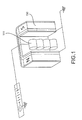
- a mass spectrometer may use an ion pump (see prior art FIG. 1 ) to achieve the internal vacuum associated with proper operation.
- the ion pump may achieve vacuum by ionizing molecules that drift into a cylindrical anode, then driving them to a cathode surface using an electric field.
- the ions thus sequestered in the cathode material may be removed from the vacuum space, and consequently, the pressure within the mass spectrometer may be reduced.
- the ion pump is a limited-life item due to, for instance, degradation of a cathode surface occurring as a consequence of ion bombardment.
- An increased ion pump life is desired for many mass spectrometer applications, especially for applications involving remote sensing where the mass spectrometer is not easily accessed or serviced. Consequently, improvements to the manner in which the cathode surface is consumed should increase the lifetime and durability of the ion pump.
- This patent describes one or more manner in which the cathode lifetime may be extended.
- an ion pump system may comprise a generally cylindrical anode tube and cathode plates.
- the ion pump system may comprise a plurality of deflection plates.
- the plurality of deflection plates may be configured to steer a trajectory of an accelerated ion off the mechanical center axis of the anode tube.
- the anode tube may comprise a first pair of integrally formed deflection plates and a second pair of integrally formed deflection plates.
- the first pair of integrally formed deflection plates may be associated with a different voltage than a voltage applied to the second pair of integrally formed deflection plates at a given time.
- An alternating current (AC) may be applied to at least one of the first pair of integrally formed deflection plates or the second pair of integrally formed deflection plates.
- the first pair of integrally formed deflection plates and the second pair of integrally formed deflection plates are substantially equivalent in size and shape.
- the anode tube comprises three integrally formed deflection plates.
- the plurality of deflection plates are disposed between an end of the generally cylindrical anode tube and a cathode plate.
- a first current carrying wire and a second current carrying wire are positioned within an anode tube and configured to change a local electric field and the trajectory of accelerated ions.
- the anode tube comprises a heterogeneous shape.
- a cathode plate of an ion pump comprising a front surface, a back surface, and additional material extending in the Z axis from at least one of the front surface or the back surface is disclosed.
- the additional material is contained within a footprint formed by an open end of an anode tube along an axis.
- the additional material may form a substantially symmetrical shape along an axial center axis in the Z direction.
- the axial center axis is collocated with the mechanical axial center axis of an anode tube.
- the axial center axis is asymmetric with the mechanical axial center axis of an anode tube.
- the positon of the axial center axis is configured to change a local electric field and the trajectory of accelerated ions over time.
- the additional material is integrally formed with the cathode plate.
- the additional material is configured to extend the lifespan of the ion pump.
- the present disclosure relates to ion pump systems and their components.
- the ion pump may comprise a series of generally cylindrical tubes referred to herein as anode tubes 200.
- a positive 4,000 Volt bias may be applied to each anode tube 200.
- the anode tubes 200 may be arranged in an array, such as a one by four or a two by four array.
- a cathode plate 250 in close proximity to an end of the anode tube may be held at a ground voltage.
- Electrons generated via the Penning effect ionize the molecules, which then accelerate toward a cathode surface. Upon impact, the ion may be sequestered in the cathode. At the same time, they may also cause ejection of material from the cathode surface. Over time, enough material is ejected to create a pit in the cathode, and eventually a hole may be drilled through the cathode, rendering it useless. If the drilling continues, it is possible to breach the vacuum housing behind the cathode and cause an ion pump failure.
- the tightly focused ion beam comes out the axial center of the anode tube with minimal dispersion. This is why the burned-through portion of the cathode may be aligned with the axial center of the anode tube and result in a small footprint as compared with the diameter of the anode tube.
- the ion beam is manipulated such that a wide footprint of the cathode surface is impacted. Dispersing the striking path of the electrons on the order of 1 ⁇ 2 of the conventional non-dispersed striking path may triple the life of the cathode surface and in turn extend the lifespan of the ion pump system.
- a dimple may be formed in the cathode plate 150 generally centered along this axis for each anode tube 100.
- 8 dimples may be formed in the cathode plate 150. This dimple may increase in depth until it progresses through the cathode plate 150. Manipulating the accelerated ions' path of travel may result in an increased lifespan for the cathode plate 150 and ion pump.
- This manipulation may be achieved by either steering the accelerated ion and/or passively defocusing the path of travel of the accelerated ion. This manipulation may be achieved in a variety of ways.
- the anode tube 200 may be sectioned.
- the anode tube 200 may be sectioned into deflection plates.
- the anode tube 200 may be sectioned into a pair of deflection plates.
- the generally cylindrical anode tube 200 may be comprised of 4 substantially equal sized sections, (e.g., first section 210, second section 215, third section 220 and fourth section 225).
- a constant positive 4,000 Volts may be applied to each deflection plate, first section 210, second section 215, third section 220 and fourth section 225 via a power source and/or control unit 205 coupled to each anode tube 200.
- a small time variant field such as an AC field of 100 Volts plus or minus from the reference voltage, (e.g., 4,000 Volts) may be applied between a pair of deflection plates, such as between first section 210, and second section 215 and/or between third section 220 and fourth section 225 via the power source and/or control unit 205 coupled to each anode tube 200.
- This AC field may be applied at any frequency, such as 60 Hz.
- the position of the ion within the anode tube along with the electric field at that location based on the frequency of the AC field and the reference voltage may determine a trajectory of the accelerated ion.
- the ions In response to statically altering the potential on one of an opposing pair of deflection plates, the ions will move the center axis off the physical center axis (e.g., A-A') of that anode tube 200. Thus, the ions path of travel will be altered from being collated with the physical center axis of the anode tube.
- a time varying field such as an alternating current field, may be applied to each pair of deflection plates, such as between first section 210, and second section 215 and/or between third section 220 and fourth section 225 at different times.
- Accelerated ions leave the center portion (near axis A-A') of the anode tube 200 due to the anode tube 200 symmetry and the generally symmetrical electric fields present.
- the apparent symmetry within the anode tube 200 may be altered by making the anode tube 200 longitudinally segmented and applying independent voltages to each segment, such as between first section 210, and second section 215 and/or between third section 220 and fourth section 225.
- the voltages on two adjacent segments may be time varied at different rates to achieve the same rasterizing process described above.
- an anode tube 300 may be sectioned into a set of three deflection plates, a first deflection plate 310, a second deflection plate 315 and a third deflection plate 318.
- the first deflection plate 310, the second deflection plate 315 and the third deflection plate 318 may be substantially equally sized.
- a reference voltage such as a positive 4,000 Volts, may be applied to two of the three deflection plates at any given time such as time X via a power source and/or control unit 205 coupled to each anode tube 300.
- the remaining deflection plate may comprise a different amount of voltage, such as a plus or minus 100 Volts, such as 4,100 Volts, at any given time, such as time X.
- the deflection plate being applied the additional 100 volts may be time variant. This will passively steer the vector of an accelerated ion in a nearly random path away from the center axis, (axis B-B') of the anode tube 300 depending on which deflection plate, (the first deflection plate 310, the second deflection plate 315 or the third deflection plate 318) is being applied the additional 100 volts at any given time.
- one or more current carrying wire such as wires (first wire 430 and second wire 435), may be positioned within a single section anode tube 400.
- the first wire 430 and second wire 435 may be coupled to a power source and/or control unit 205.
- the power source and/or control unit 205 may be coupled to each anode tube 400.
- the single section anode tube may be similar in geometry to conventional anode tubes 100.
- the direction of travel of the one or more wires may be spiraled, axially aligned with the center axis (axis C-C') of the anode tube 400 and/or randomly positioned.
- An AC voltage such as 100 Volts plus or minus from a reference voltage, may be applied to the wires 430 and 435. Stated another way, a periodic voltage may be applied to the wires 430 and 435. This may alter the electric field within the anode tube away from directing an accelerated ion along axis A-A'.
- An ion formed at any time and/or thus a particle cloud, such as an electron cloud
- the electron cloud may be steered off axis.
- multiple diffusion plates and/or a plurality of pairs of diffusion plates may be positioned between the anode tube 500 and the cathode plate 250.
- a reference voltage such as a positive 4,000 Volts, may be applied to each anode tube 500, via a control unit 205 and/or power source.
- a small time variant field such as an AC field of 100 Volts plus or minus from a reference voltage, (e.g., 4,000 Volts) may be applied between a pair of deflection plates, such as between first deflection plate 510 and second deflection plate 515 and/or between third deflection plate 520 and fourth deflection plate 525.
- a pair of deflection plates such as between first deflection plate 510 and second deflection plate 515 and/or between third deflection plate 520 and fourth deflection plate 525.
- an ion formed at any time may be steered off the mechanical center axis (e.g., axis D-D') of each anode tube 500.
- the accelerated ion can be moved after it leaves the anode tube 500 using a secondary electrode disposed between the anode tube 500 and the cathode plate 250.
- the secondary electrode would be segmented, allowing different time-dependent voltages to be applied to each segment, and configured to alter the electric field within the electrode and steering the accelerated ion as desired.
- Three electrodes may be utilized to achieve full X axis and Y axis control of the accelerated ion, and additional segmented electrode designs are also feasible.
- a common set of steering electrodes could be used for a multi-anode tube ion pump.
- the accelerated ion may be rasterized systematically across the cathode plate 250 surface at high speed.
- the shape of the anode tube 600, 610 along the axial direction can be varied near the ends of the anode tube.
- the various anode tubes disclosed herein may be combined with the principles of FIG. 6A , wherein, for example, the anode tube 600 may include one transition section 601 whereby one or more 603 of the anode tube may have a shape that fills gaps in the end of the array (such as in a 2x4 stacked array shown in Figure 2 ) wherein one end 603 would become square as depicted in FIG. 6A to fill the gaps between the cylinder portion 605 of adjacent anode tubes 600.
- the various anode tubes disclosed herein may be combined with the principles of FIG. 6B , wherein, for example, the anode tube 610 may include a transition section 601 at each end 603 of the anode tube 610 whereby each end 603 of the anode tube 610 may have a shape that fills gaps in the end of the array (such as in a 2x4 stacked array shown in Figure 2 ) wherein each end 603 would become square as depicted in FIG. 6B to fill the gaps between the cylinder portion 605 of adjacent anode tubes 610.
- an anode tube 600, 610 may comprise any variable shape as desired.
- the anode tube 600, 610 may be flared to form a larger diameter (such as for a single anode design).
- the electric field thus generated near the ends of the anode tube 600, 610 may be radially more diffuse, increasing the radial trajectory of any off-axis ion exiting the anode tube 600, 610 and broadening the impacted cathode area.
- Thickening the cathode plate 650, with reference to FIG. 7 , in desired areas may result in an increased lifespan for the cathode plate and ion pump. While the entire cathode plate 650 may be thickened to increase the lifespan for the cathode plate and ion pump, in some applications the material weight may be undesirable, such as in aerospace applications.
- additional material 675 may be integrally formed in the cathode plate back surface 655, such as the surface farthest to an exit of the anode tube.
- additional material 675 formed from the same material and integral to the cathode plate 650 may extend from the cathode plate back surface 655 in a direction along the Z axis away from an exit of the anode tube.
- the additional material 675 may form a Gaussian toroid shape.
- the additional material 675 may form a cylinder aligned with the footprint of the anode tube.
- the additional material 675 may form a symmetrical shape along axis A-A' which may be the mechanical center axis of an anode tube.
- the additional material 675 may form a cylinder of any desired radius with a center axis aligned with the mechanical center axis A-A' of the anode tube.
- additional material 775 may be integrally formed in the cathode plate front surface 745, such as the surface closest to an exit of the anode tube.
- additional material 775 formed from the same material and integral to the cathode plate 750 may extend from the cathode plate front surface 745 in a direction along the Z axis proximate from an exit of the anode tube.
- the additional material 775 may form a Gaussian toroid shape.
- the additional material 775 may form a cylinder aligned with the footprint of an anode tube.
- the additional material 775 may form a symmetrical shape along axis A-A' which may be the mechanical center axis of an anode tube.
- the additional material 775 may form a cylinder of any desired radius with a center axis aligned with the mechanical center axis A-A' of the anode tube.
- additional material 875 may extend in a direction along the Z axis from the cathode plate front surface 845 or cathode plate back surface 855.
- the additional material 875 may be generally symmetrical about additional material 875 along a centerline E-E', wherein the centerline is offset from the mechanical center axis of the anode tube A-A'.
- the vector of the accelerated ion is off center.
- the ions will impact the additional material 875.
- the ions will impact the additional material 875 a relatively higher percentage of the time near the mechanical center axis of the anode tube A-A' but offset from the mechanical center axis of the anode tube A-A'.
- the additional material 875 may be ablated away, which will alter the shape of the electric field experienced by incoming accelerated ions.
- the electric field experienced by incoming accelerated ions is passively changed.
- the accelerated ions will be steered into different sections of the cathode plate 850, generally within the footprint of the anode tube over time.
- the deformity to the cathode surface may be axially asymmetric to the ion beam axis A-A'.
- This arrangement may be configured to distort the electric field and alter the trajectory of the accelerated ion. As the accelerated ion interacts with and/or ablated the additional material 875 with the cathode over time and material is removed, the deformity will be altered as well, changing the local electric field, and consequently, the trajectory of the accelerated ion.
- the concepts described herein may apply to terrestrial ion pumps and/or aerospace based ion pumps, such as sputter ion pumps.
- references to "various embodiments”, “one embodiment”, “an embodiment”, “an example embodiment”, etc. indicate that the embodiment described may include a particular feature, structure, or characteristic, but every embodiment may not necessarily include the particular feature, structure, or characteristic. Moreover, such phrases are not necessarily referring to the same embodiment. Further, when a particular feature, structure, or characteristic is described in connection with an embodiment, it is submitted that it is within the knowledge of one skilled in the art to affect such feature, structure, or characteristic in connection with other embodiments whether or not explicitly described. After reading the description, it will be apparent to one skilled in the relevant art(s) how to implement the disclosure in alternative embodiments. Different cross-hatching is used throughout the figures to denote different parts but not necessarily to denote the same or different materials.
Landscapes
- Electron Tubes For Measurement (AREA)
Abstract
Description
- The present disclosure relates to ion pump systems and their components.
- Mass spectrometers operate in a vacuum environment that requires a pumping mechanism to establish and maintain low pressure. In various pumping methodologies, a mass spectrometer may use an ion pump (see prior art
FIG. 1 ) to achieve the internal vacuum associated with proper operation. The ion pump may achieve vacuum by ionizing molecules that drift into a cylindrical anode, then driving them to a cathode surface using an electric field. The ions thus sequestered in the cathode material may be removed from the vacuum space, and consequently, the pressure within the mass spectrometer may be reduced. - The ion pump is a limited-life item due to, for instance, degradation of a cathode surface occurring as a consequence of ion bombardment. An increased ion pump life is desired for many mass spectrometer applications, especially for applications involving remote sensing where the mass spectrometer is not easily accessed or serviced. Consequently, improvements to the manner in which the cathode surface is consumed should increase the lifetime and durability of the ion pump. This patent describes one or more manner in which the cathode lifetime may be extended.
- The present disclosure relates to ion pump systems and their components. According to various embodiments, an ion pump system is disclosed. The ion pump system may comprise a generally cylindrical anode tube and cathode plates. The ion pump system may comprise a plurality of deflection plates. The plurality of deflection plates may be configured to steer a trajectory of an accelerated ion off the mechanical center axis of the anode tube.
- The anode tube may comprise a first pair of integrally formed deflection plates and a second pair of integrally formed deflection plates. The first pair of integrally formed deflection plates may be associated with a different voltage than a voltage applied to the second pair of integrally formed deflection plates at a given time. An alternating current (AC) may be applied to at least one of the first pair of integrally formed deflection plates or the second pair of integrally formed deflection plates. The first pair of integrally formed deflection plates and the second pair of integrally formed deflection plates are substantially equivalent in size and shape.
- According to various embodiments, the anode tube comprises three integrally formed deflection plates. According to various embodiments, the plurality of deflection plates are disposed between an end of the generally cylindrical anode tube and a cathode plate. According to various embodiments, a first current carrying wire and a second current carrying wire are positioned within an anode tube and configured to change a local electric field and the trajectory of accelerated ions. According to various embodiments, the anode tube comprises a heterogeneous shape. According to various embodiments, a cathode plate of an ion pump comprising a front surface, a back surface, and additional material extending in the Z axis from at least one of the front surface or the back surface is disclosed. The additional material is contained within a footprint formed by an open end of an anode tube along an axis. The additional material may form a substantially symmetrical shape along an axial center axis in the Z direction. The axial center axis is collocated with the mechanical axial center axis of an anode tube. The axial center axis is asymmetric with the mechanical axial center axis of an anode tube. The positon of the axial center axis is configured to change a local electric field and the trajectory of accelerated ions over time. The additional material is integrally formed with the cathode plate. The additional material is configured to extend the lifespan of the ion pump.
- The subject matter of the present disclosure is particularly pointed out and distinctly claimed in the concluding portion of the specification. A more complete understanding of the present disclosure, however, may best be obtained by referring to the detailed description and claims when considered in connection with the drawing figures, wherein like numerals denote like elements.
-
FIG. 1 depicts a prior art ion pump system; -
FIG. 2A depicts an isometric view of an ion pump system in accordance with various embodiments; -
FIG. 2B depicts an isometric view of an ion pump anode tube in accordance with various embodiments; -
FIG. 2C depicts an end view of an ion pump anode tube ofFIG. 2B in accordance with various embodiments; -
FIG. 3A depicts an isometric view of an ion pump system in accordance with various embodiments; -
FIG. 3B depicts an isometric view of an ion pump anode tube in accordance with various embodiments; -
FIG. 3C depicts an end view of an ion pump anode tube ofFIG. 3B in accordance with various embodiments; -
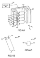
FIG. 4A depicts an isometric view of an ion pump system in accordance with various embodiments; -
FIG. 4B depicts an isometric view of an ion pump anode tube in accordance with various embodiments; -
FIG. 4C depicts an end view of an ion pump anode tube ofFIG. 4B in accordance with various embodiments; -
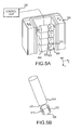
FIG. 5A depicts an isometric view of an ion pump system in accordance with various embodiments; -
FIG. 5B depicts an isometric view of an ion pump anode tube in accordance with various embodiments; -
FIG. 6A depicts an isometric view of a ion pump anode tube having a flared aspect in accordance with various embodiments; -
FIG. 6B depicts an isometric view of a ion pump anode tube having dual flared aspects in accordance with various embodiments; -
FIG. 7 depicts a cathode having increased material positioned on a back face of the cathode, in accordance with various embodiments; -
FIG. 8 depicts a cathode having increased material positioned on a front face of the cathode, in accordance with various embodiments; and -
FIG. 9 depicts a cathode having increased material positioned off a centerline axis of the anode tube, in accordance with various embodiments. - The detailed description of exemplary embodiments herein makes reference to the accompanying drawings, which show exemplary embodiments by way of illustration and their best mode. While these exemplary embodiments are described in sufficient detail to enable those skilled in the art to practice the disclosure, it should be understood that other embodiments may be realized and that logical changes may be made without departing from the scope of the disclosure. Thus, the detailed description herein is presented for purposes of illustration only and not of limitation. For example, the steps recited in any of the method or process descriptions may be executed in any order and are not necessarily limited to the order presented. Furthermore, any reference to singular includes plural embodiments, and any reference to more than one component or step may include a singular embodiment or step.
- The present disclosure relates to ion pump systems and their components. According to various embodiments and with reference to
FIG. 2A , an ion pump system is depicted. The ion pump may comprise a series of generally cylindrical tubes referred to herein asanode tubes 200. A positive 4,000 Volt bias may be applied to eachanode tube 200. Theanode tubes 200 may be arranged in an array, such as a one by four or a two by four array. Acathode plate 250 in close proximity to an end of the anode tube may be held at a ground voltage. - Under normal operation of the ion pump, molecules drift into an open cylindrical anode, such as an anode tube having a high voltage potential. Electrons generated via the Penning effect ionize the molecules, which then accelerate toward a cathode surface. Upon impact, the ion may be sequestered in the cathode. At the same time, they may also cause ejection of material from the cathode surface. Over time, enough material is ejected to create a pit in the cathode, and eventually a hole may be drilled through the cathode, rendering it useless. If the drilling continues, it is possible to breach the vacuum housing behind the cathode and cause an ion pump failure.
- The tightly focused ion beam comes out the axial center of the anode tube with minimal dispersion. This is why the burned-through portion of the cathode may be aligned with the axial center of the anode tube and result in a small footprint as compared with the diameter of the anode tube.
- According to various embodiments, the ion beam is manipulated such that a wide footprint of the cathode surface is impacted. Dispersing the striking path of the electrons on the order of ½ of the conventional non-dispersed striking path may triple the life of the cathode surface and in turn extend the lifespan of the ion pump system.
- With renewed reference to
FIG. 1 , as the accelerated ions are generally accelerated along the mechanical center axis of theanode tube 100, a greater percentage of the accelerated ions strike proximate this axis. Over time, a dimple may be formed in thecathode plate 150 generally centered along this axis for eachanode tube 100. Thus, in the case of 8 anode tubes, 8 dimples may be formed in thecathode plate 150. This dimple may increase in depth until it progresses through thecathode plate 150. Manipulating the accelerated ions' path of travel may result in an increased lifespan for thecathode plate 150 and ion pump. - This manipulation may be achieved by either steering the accelerated ion and/or passively defocusing the path of travel of the accelerated ion. This manipulation may be achieved in a variety of ways.
- According to various embodiments and with renewed reference to
FIGs. 2A, 2B and 2C , theanode tube 200 may be sectioned. Theanode tube 200 may be sectioned into deflection plates. For instance, theanode tube 200 may be sectioned into a pair of deflection plates. For instance, the generallycylindrical anode tube 200 may be comprised of 4 substantially equal sized sections, (e.g.,first section 210,second section 215,third section 220 and fourth section 225). A constant positive 4,000 Volts may be applied to each deflection plate,first section 210,second section 215,third section 220 andfourth section 225 via a power source and/orcontrol unit 205 coupled to eachanode tube 200. A small time variant field, such as an AC field of 100 Volts plus or minus from the reference voltage, (e.g., 4,000 Volts), may be applied between a pair of deflection plates, such as betweenfirst section 210, andsecond section 215 and/or betweenthird section 220 andfourth section 225 via the power source and/orcontrol unit 205 coupled to eachanode tube 200. This AC field may be applied at any frequency, such as 60 Hz. The position of the ion within the anode tube along with the electric field at that location based on the frequency of the AC field and the reference voltage may determine a trajectory of the accelerated ion. In response to statically altering the potential on one of an opposing pair of deflection plates, the ions will move the center axis off the physical center axis (e.g., A-A') of thatanode tube 200. Thus, the ions path of travel will be altered from being collated with the physical center axis of the anode tube. In this way, a time varying field, such as an alternating current field, may be applied to each pair of deflection plates, such as betweenfirst section 210, andsecond section 215 and/or betweenthird section 220 andfourth section 225 at different times. Thus, there is a high probability that an ion formed and ejected through theanode tube 200 will not see the exact same electric field as a different ion formed inanode tube 200 and ejected at a different time. Consequently, the vector of the ejected ion will strikecathode plate 250 at a different location than an ion formed at a later time. Thus, the accelerated ion will strike thecathode plate 250 in a generally random pattern with respect to the X and Y axis, in contrast to along a central axis of the anode tube as was common in conventional systems such as the ion pump depicted inFIG. 1 . - Accelerated ions leave the center portion (near axis A-A') of the
anode tube 200 due to theanode tube 200 symmetry and the generally symmetrical electric fields present. The apparent symmetry within theanode tube 200 may be altered by making theanode tube 200 longitudinally segmented and applying independent voltages to each segment, such as betweenfirst section 210, andsecond section 215 and/or betweenthird section 220 andfourth section 225. The voltages on two adjacent segments may be time varied at different rates to achieve the same rasterizing process described above. - According to various embodiments and with reference to
FIGs. 3A, 3B, and 3C , ananode tube 300 may be sectioned into a set of three deflection plates, afirst deflection plate 310, asecond deflection plate 315 and athird deflection plate 318. Thefirst deflection plate 310, thesecond deflection plate 315 and thethird deflection plate 318 may be substantially equally sized. A reference voltage such as a positive 4,000 Volts, may be applied to two of the three deflection plates at any given time such as time X via a power source and/orcontrol unit 205 coupled to eachanode tube 300. The remaining deflection plate may comprise a different amount of voltage, such as a plus or minus 100 Volts, such as 4,100 Volts, at any given time, such as time X. The deflection plate being applied the additional 100 volts may be time variant. This will passively steer the vector of an accelerated ion in a nearly random path away from the center axis, (axis B-B') of theanode tube 300 depending on which deflection plate, (thefirst deflection plate 310, thesecond deflection plate 315 or the third deflection plate 318) is being applied the additional 100 volts at any given time. - According to various embodiments and with reference to
FIGs. 4A, 4B, and 4C , one or more current carrying wire, such as wires (first wire 430 and second wire 435), may be positioned within a singlesection anode tube 400. Thefirst wire 430 andsecond wire 435 may be coupled to a power source and/orcontrol unit 205. The power source and/orcontrol unit 205 may be coupled to eachanode tube 400. The single section anode tube may be similar in geometry toconventional anode tubes 100. The direction of travel of the one or more wires may be spiraled, axially aligned with the center axis (axis C-C') of theanode tube 400 and/or randomly positioned. An AC voltage, such as 100 Volts plus or minus from a reference voltage, may be applied to thewires wires anode tube 400. Moreover, the electron cloud may be steered off axis. - According to various embodiments and with reference to
FIGs. 5A, and 5B , rather than portioning the anode tubes into sections, multiple diffusion plates and/or a plurality of pairs of diffusion plates may be positioned between theanode tube 500 and thecathode plate 250. A reference voltage, such as a positive 4,000 Volts, may be applied to eachanode tube 500, via acontrol unit 205 and/or power source. A small time variant field, such as an AC field of 100 Volts plus or minus from a reference voltage, (e.g., 4,000 Volts), may be applied between a pair of deflection plates, such as betweenfirst deflection plate 510 andsecond deflection plate 515 and/or betweenthird deflection plate 520 andfourth deflection plate 525. Based on the disruption to the electric and magnetic fields, an ion formed at any time may be steered off the mechanical center axis (e.g., axis D-D') of eachanode tube 500. - Stated another way, the accelerated ion can be moved after it leaves the
anode tube 500 using a secondary electrode disposed between theanode tube 500 and thecathode plate 250. The secondary electrode would be segmented, allowing different time-dependent voltages to be applied to each segment, and configured to alter the electric field within the electrode and steering the accelerated ion as desired. - Three electrodes may be utilized to achieve full X axis and Y axis control of the accelerated ion, and additional segmented electrode designs are also feasible. A common set of steering electrodes could be used for a multi-anode tube ion pump. The accelerated ion may be rasterized systematically across the
cathode plate 250 surface at high speed. - According to various embodiments and with reference to
FIGs. 6A-B , the shape of theanode tube FIG. 6A , wherein, for example, theanode tube 600 may include onetransition section 601 whereby one or more 603 of the anode tube may have a shape that fills gaps in the end of the array (such as in a 2x4 stacked array shown inFigure 2 ) wherein oneend 603 would become square as depicted inFIG. 6A to fill the gaps between thecylinder portion 605 ofadjacent anode tubes 600. In accordance with various embodiments, the various anode tubes disclosed herein may be combined with the principles ofFIG. 6B , wherein, for example, theanode tube 610 may include atransition section 601 at eachend 603 of theanode tube 610 whereby eachend 603 of theanode tube 610 may have a shape that fills gaps in the end of the array (such as in a 2x4 stacked array shown inFigure 2 ) wherein eachend 603 would become square as depicted inFIG. 6B to fill the gaps between thecylinder portion 605 ofadjacent anode tubes 610. Moreover, with reference toFIGs. 6A-B , ananode tube anode tube anode tube anode tube - Thickening the
cathode plate 650, with reference toFIG. 7 , in desired areas may result in an increased lifespan for the cathode plate and ion pump. While theentire cathode plate 650 may be thickened to increase the lifespan for the cathode plate and ion pump, in some applications the material weight may be undesirable, such as in aerospace applications. - According to various embodiments and with reference to
FIG. 7 ,additional material 675 may be integrally formed in the cathode plate backsurface 655, such as the surface farthest to an exit of the anode tube. In this way,additional material 675 formed from the same material and integral to thecathode plate 650 may extend from the cathode plate backsurface 655 in a direction along the Z axis away from an exit of the anode tube. Theadditional material 675 may form a Gaussian toroid shape. Theadditional material 675 may form a cylinder aligned with the footprint of the anode tube. Theadditional material 675 may form a symmetrical shape along axis A-A' which may be the mechanical center axis of an anode tube. Theadditional material 675 may form a cylinder of any desired radius with a center axis aligned with the mechanical center axis A-A' of the anode tube. - According to various embodiments and with reference to
FIG. 8 ,additional material 775 may be integrally formed in the cathode platefront surface 745, such as the surface closest to an exit of the anode tube. In this way,additional material 775 formed from the same material and integral to thecathode plate 750 may extend from the cathode platefront surface 745 in a direction along the Z axis proximate from an exit of the anode tube. Theadditional material 775 may form a Gaussian toroid shape. Theadditional material 775 may form a cylinder aligned with the footprint of an anode tube. Theadditional material 775 may form a symmetrical shape along axis A-A' which may be the mechanical center axis of an anode tube. Theadditional material 775 may form a cylinder of any desired radius with a center axis aligned with the mechanical center axis A-A' of the anode tube. - According to various embodiments and with reference to
FIG. 9 ,additional material 875 may extend in a direction along the Z axis from the cathode platefront surface 845 or cathode plate back surface 855. Theadditional material 875 may be generally symmetrical aboutadditional material 875 along a centerline E-E', wherein the centerline is offset from the mechanical center axis of the anode tube A-A'. - A cathode plate with an extension that is offset from the mechanical center axis of the anode tube A-A' distorts the electric field felt by the incoming accelerated ion. Thus, the vector of the accelerated ion is off center. Over time, the ions will impact the
additional material 875. The ions will impact the additional material 875 a relatively higher percentage of the time near the mechanical center axis of the anode tube A-A' but offset from the mechanical center axis of the anode tube A-A'. Over time, theadditional material 875 may be ablated away, which will alter the shape of the electric field experienced by incoming accelerated ions. In this way, by ablating theadditional material 875 over time, the electric field experienced by incoming accelerated ions is passively changed. Thus, the accelerated ions will be steered into different sections of the cathode plate 850, generally within the footprint of the anode tube over time. - In this way the deformity to the cathode surface (e.g., the additional material 875), may be axially asymmetric to the ion beam axis A-A'. This arrangement may be configured to distort the electric field and alter the trajectory of the accelerated ion. As the accelerated ion interacts with and/or ablated the
additional material 875 with the cathode over time and material is removed, the deformity will be altered as well, changing the local electric field, and consequently, the trajectory of the accelerated ion. - The concepts described herein may apply to terrestrial ion pumps and/or aerospace based ion pumps, such as sputter ion pumps.
- Benefits, other advantages, and solutions to problems have been described herein with regard to specific embodiments. Furthermore, the connecting lines shown in the various figures contained herein are intended to represent exemplary functional relationships and/or physical couplings between the various elements. It should be noted that many alternative or additional functional relationships or physical connections may be present in a practical system. However, the benefits, advantages, solutions to problems, and any elements that may cause any benefit, advantage, or solution to occur or become more pronounced are not to be construed as critical, required, or essential features or elements of the disclosure. The scope of the disclosure is accordingly to be limited by nothing other than the appended claims, in which reference to an element in the singular is not intended to mean "one and only one" unless explicitly so stated, but rather "one or more."
- Systems, methods and apparatus are provided herein. In the detailed description herein, references to "various embodiments", "one embodiment", "an embodiment", "an example embodiment", etc., indicate that the embodiment described may include a particular feature, structure, or characteristic, but every embodiment may not necessarily include the particular feature, structure, or characteristic. Moreover, such phrases are not necessarily referring to the same embodiment. Further, when a particular feature, structure, or characteristic is described in connection with an embodiment, it is submitted that it is within the knowledge of one skilled in the art to affect such feature, structure, or characteristic in connection with other embodiments whether or not explicitly described. After reading the description, it will be apparent to one skilled in the relevant art(s) how to implement the disclosure in alternative embodiments. Different cross-hatching is used throughout the figures to denote different parts but not necessarily to denote the same or different materials.
Claims (15)
- A cathode plate (250; 650; 750; 850) of an ion pump comprising:a front surface (745; 845);a back surface (655; 855); andan additional material (775; 875) extending from the front surface (745; 845), wherein the cathode plate (250 ... 850) is located in proximity to an anode tube (200; 300; 400; 500; 600; 610), wherein the front surface (745; 845) is in closer proximity to the anode tube (200 ... 610) than the back surface (655; 855).
- The cathode plate of an ion pump of claim 1, wherein the additional material (775; 875) is contained within a footprint defined by and projected to the cathode plate (250 ... 850) from an open end of the anode tube (200 ... 610) along an axis.
- The cathode plate of an ion pump of claim 1 or 2, wherein the additional material (775; 875) forms a substantially symmetrical shape along an axial center axis (E-E') in a Z direction.
- The cathode plate of an ion pump of claim 3, wherein the axial center axis (E-E') is collocated with a mechanical axial center axis (A-A) of the anode tube (200 ... 610).
- The cathode plate of an ion pump of claim 3 or 4, wherein the axial center axis (E-E) is asymmetric with a/the mechanical axial center axis (A-A) of the anode tube (200 ... 610).
- The cathode plate of an ion pump of claim 3, 4 or 5, wherein a positon of the axial center axis (E-E') of the additional material (775; 875) is configured to change a local electric field and a trajectory of accelerated ions over time by varying an electric field as material of the additional material (775; 875) is ablated by accelerated ions.
- The cathode plate of an ion pump of any preceding claim, wherein the additional material (775; 875) is integrally formed with the cathode plate (250 ... 850).
- A cathode plate (250 ... 850) of an ion pump comprising:a front surface (745; 845);a back surface (655; 855); andan additional material (775; 875) extending from the back surface (655; 855), wherein the cathode plate (250 ... 850) is located in proximity to an anode tube (200 ... 610), wherein the front surface (745; 845) is in closer proximity to the anode tube (200 ... 610) than the back surface (655; 855).
- he cathode plate of an ion pump of claim 8, wherein the additional material (775; 875) is contained within a footprint defined by and projected to the cathode plate (250 ... 850) from an open end of the anode tube (200 ... 610) along an axis.
- The cathode plate of an ion pump of claim 8 or 9, wherein the additional material (775; 875) forms a substantially symmetrical shape along an axial center axis (E-E') in a Z direction.
- The cathode plate of an ion pump of claim 10, wherein the axial center axis (E-E') is collocated with a mechanical axial center axis (A-A) of the anode tube (200 ... 610).
- The cathode plate of an ion pump of claim 10 or 11, wherein the axial center axis (E-E') is asymmetric with a/the mechanical axial center axis (A-A) of the anode tube (200 ... 610).
- The cathode plate of an ion pump of claim 10, 11 or 12, wherein a positon of the axial center axis (E-E') of the additional material (775; 875) is configured to change a local electric field and a trajectory of accelerated ions over time by varying an electric field as material of the additional material (775; 875) is ablated by accelerated ions.
- The cathode plate of an ion pump of any of claims 8 to 13, wherein the additional material (775; 875) is integrally formed with the cathode plate (250 ... 850).
- The cathode plate of an ion pump of any preceding claim, wherein the additional material (775; 875) is configured to extend a lifespan of the ion pump.
Priority Applications (1)
| Application Number | Priority Date | Filing Date | Title |
|---|---|---|---|
| EP21165387.8A EP3859765B1 (en) | 2015-02-10 | 2016-02-09 | Systems for enhanced ion pump lifespan |
Applications Claiming Priority (2)
| Application Number | Priority Date | Filing Date | Title |
|---|---|---|---|
| US14/618,814 US10665437B2 (en) | 2015-02-10 | 2015-02-10 | System and method for enhanced ion pump lifespan |
| US14/874,165 US10262845B2 (en) | 2015-02-10 | 2015-10-02 | System and method for enhanced ion pump lifespan |
Related Child Applications (1)
| Application Number | Title | Priority Date | Filing Date |
|---|---|---|---|
| EP21165387.8A Division EP3859765B1 (en) | 2015-02-10 | 2016-02-09 | Systems for enhanced ion pump lifespan |
Publications (2)
| Publication Number | Publication Date |
|---|---|
| EP3057121A1 true EP3057121A1 (en) | 2016-08-17 |
| EP3057121B1 EP3057121B1 (en) | 2021-04-28 |
Family
ID=55527729
Family Applications (2)
| Application Number | Title | Priority Date | Filing Date |
|---|---|---|---|
| EP21165387.8A Active EP3859765B1 (en) | 2015-02-10 | 2016-02-09 | Systems for enhanced ion pump lifespan |
| EP16154860.7A Active EP3057121B1 (en) | 2015-02-10 | 2016-02-09 | System and method for enhanced ion pump lifespan |
Family Applications Before (1)
| Application Number | Title | Priority Date | Filing Date |
|---|---|---|---|
| EP21165387.8A Active EP3859765B1 (en) | 2015-02-10 | 2016-02-09 | Systems for enhanced ion pump lifespan |
Country Status (2)
| Country | Link |
|---|---|
| US (1) | US10262845B2 (en) |
| EP (2) | EP3859765B1 (en) |
Cited By (2)
| Publication number | Priority date | Publication date | Assignee | Title |
|---|---|---|---|---|
| EP3293753A1 (en) * | 2016-09-08 | 2018-03-14 | Edwards Vacuum, LLC | Ion trajectory manipulation architecture in an ion pump |
| GB2586971A (en) * | 2019-09-06 | 2021-03-17 | Edwards Vacuum Llc | Reducing plasma formation in an ion pump |
Families Citing this family (1)
| Publication number | Priority date | Publication date | Assignee | Title |
|---|---|---|---|---|
| US10665437B2 (en) | 2015-02-10 | 2020-05-26 | Hamilton Sundstrand Corporation | System and method for enhanced ion pump lifespan |
Citations (6)
| Publication number | Priority date | Publication date | Assignee | Title |
|---|---|---|---|---|
| US3070719A (en) * | 1960-10-11 | 1962-12-25 | Varian Associates | Cathodes for magnentically-confined glow discharge apparatus |
| US3319875A (en) * | 1965-03-22 | 1967-05-16 | Varian Associates | Ion vacuum pumps |
| DE1489231A1 (en) * | 1963-03-22 | 1969-09-04 | Siemens Ag | Ion pump |
| DE1489227A1 (en) * | 1964-04-16 | 1970-07-16 | Leybold Heraeus Gmbh & Co Kg | Atomizing ion getter pump |
| DE2346841A1 (en) * | 1973-09-18 | 1975-05-07 | Leybold Heraeus Gmbh & Co Kg | ION SPRAYER PUMP |
| DE2362203A1 (en) * | 1973-12-14 | 1975-06-19 | Philips Patentverwaltung | Getter ion pump for high-vacuum tubes - has soft magnetic housing whose open ends are vacuum-tightly closed by cathode holders |
Family Cites Families (34)
| Publication number | Priority date | Publication date | Assignee | Title |
|---|---|---|---|---|
| FR955981A (en) | 1946-11-27 | 1950-01-23 | ||
| NL256013A (en) | 1959-09-25 | |||
| US3107844A (en) | 1959-11-12 | 1963-10-22 | Ultek Corp | Single cell vacuum apparatus |
| US3161802A (en) | 1960-05-27 | 1964-12-15 | Varian Associates | Sputtering cathode type glow discharge device vacuum pump |
| NL292484A (en) | 1962-05-09 | |||
| US3310226A (en) | 1965-02-11 | 1967-03-21 | Nat Res Corp | Vacuum device |
| US3327931A (en) | 1965-09-13 | 1967-06-27 | Charles L Hall | Ion-getter vacuum pump and gauge |
| US3531675A (en) | 1967-02-28 | 1970-09-29 | Tektronix Inc | Cathode ray storage tube having a target dielectric with collector electrodes extending therethrough |
| US3687665A (en) | 1967-02-28 | 1972-08-29 | Tektronix Inc | Method of manufacturing cathode ray storage tube target |
| US3416722A (en) | 1967-04-05 | 1968-12-17 | Varian Associates | High vacuum pump employing apertured penning cells driving ion beams into a target covered by a getter sublimator |
| US3460745A (en) | 1967-08-23 | 1969-08-12 | Varian Associates | Magnetically confined electrical discharge getter ion vacuum pump having a cathode projection extending into the anode cell |
| US3540812A (en) * | 1968-04-12 | 1970-11-17 | Rca Corp | Sputter ion pump |
| US4361472A (en) | 1980-09-15 | 1982-11-30 | Vac-Tec Systems, Inc. | Sputtering method and apparatus utilizing improved ion source |
| GB2164202A (en) | 1984-09-05 | 1986-03-12 | Philips Electronic Associated | Charged particle beam apparatus |
| US4835399A (en) | 1986-08-22 | 1989-05-30 | Hitachi, Ltd. | Charged particle beam apparatus |
| JPH07120516B2 (en) | 1990-07-26 | 1995-12-20 | 株式会社東芝 | Low energy electron irradiation method and irradiation device |
| US5340983A (en) | 1992-05-18 | 1994-08-23 | The State Of Oregon Acting By And Through The State Board Of Higher Education On Behalf Of Oregon State University | Method and apparatus for mass analysis using slow monochromatic electrons |
| KR19990022867A (en) | 1995-06-13 | 1999-03-25 | 니콜라스 제이, 키르흐너 | Improved parallel ion optics and devices for generating high current, low energy ion beams |
| US5646488A (en) * | 1995-10-11 | 1997-07-08 | Warburton; William K. | Differential pumping stage with line of sight pumping mechanism |
| FR2740607B1 (en) * | 1995-10-27 | 1997-11-21 | Commissariat Energie Atomique | IONIC PUMP WITH ADJUSTED ANODE |
| AU3126697A (en) * | 1996-05-14 | 1997-12-05 | Analytica Of Branford, Inc. | Ion transfer from multipole ion guides into multipole ion guides and ion traps |
| US5864137A (en) | 1996-10-01 | 1999-01-26 | Genetrace Systems, Inc. | Mass spectrometer |
| US6417511B1 (en) | 2000-07-17 | 2002-07-09 | Agilent Technologies, Inc. | Ring pole ion guide apparatus, systems and method |
| WO2002056332A1 (en) | 2001-01-10 | 2002-07-18 | Ebara Corporation | Inspection apparatus and inspection method with electron beam, and device manufacturing method comprising the inspection apparatus |
| US6727495B2 (en) | 2002-01-17 | 2004-04-27 | Agilent Technologies, Inc. | Ion mobility spectrometer with high ion transmission efficiency |
| US20040062659A1 (en) * | 2002-07-12 | 2004-04-01 | Sinha Mahadeva P. | Ion pump with combined housing and cathode |
| US7423275B2 (en) | 2004-01-15 | 2008-09-09 | Intel Corporation | Erosion mitigation for collector optics using electric and magnetic fields |
| CN102150219B (en) | 2008-07-28 | 2015-01-28 | 莱克公司 | Method and apparatus for ion manipulation using mesh in a radio frequency field |
| US8933397B1 (en) | 2012-02-02 | 2015-01-13 | University of Northern Iowa Research Foundati | Ion trap mass analyzer apparatus, methods, and systems utilizing one or more multiple potential ion guide (MPIG) electrodes |
| DE102012223450B4 (en) * | 2012-12-17 | 2019-07-04 | Pfeiffer Vacuum Gmbh | Vacuum pump with ionization pump stage |
| US20150311048A1 (en) * | 2014-04-24 | 2015-10-29 | Honeywell International Inc. | Micro hybrid differential/triode ion pump |
| WO2015191569A1 (en) | 2014-06-13 | 2015-12-17 | Perkinelmer Health Sciences, Inc. | Rf ion guide with axial fields |
| US10665437B2 (en) | 2015-02-10 | 2020-05-26 | Hamilton Sundstrand Corporation | System and method for enhanced ion pump lifespan |
| US9704701B2 (en) | 2015-09-11 | 2017-07-11 | Battelle Memorial Institute | Method and device for ion mobility separations |
-
2015
- 2015-10-02 US US14/874,165 patent/US10262845B2/en active Active
-
2016
- 2016-02-09 EP EP21165387.8A patent/EP3859765B1/en active Active
- 2016-02-09 EP EP16154860.7A patent/EP3057121B1/en active Active
Patent Citations (6)
| Publication number | Priority date | Publication date | Assignee | Title |
|---|---|---|---|---|
| US3070719A (en) * | 1960-10-11 | 1962-12-25 | Varian Associates | Cathodes for magnentically-confined glow discharge apparatus |
| DE1489231A1 (en) * | 1963-03-22 | 1969-09-04 | Siemens Ag | Ion pump |
| DE1489227A1 (en) * | 1964-04-16 | 1970-07-16 | Leybold Heraeus Gmbh & Co Kg | Atomizing ion getter pump |
| US3319875A (en) * | 1965-03-22 | 1967-05-16 | Varian Associates | Ion vacuum pumps |
| DE2346841A1 (en) * | 1973-09-18 | 1975-05-07 | Leybold Heraeus Gmbh & Co Kg | ION SPRAYER PUMP |
| DE2362203A1 (en) * | 1973-12-14 | 1975-06-19 | Philips Patentverwaltung | Getter ion pump for high-vacuum tubes - has soft magnetic housing whose open ends are vacuum-tightly closed by cathode holders |
Cited By (5)
| Publication number | Priority date | Publication date | Assignee | Title |
|---|---|---|---|---|
| EP3293753A1 (en) * | 2016-09-08 | 2018-03-14 | Edwards Vacuum, LLC | Ion trajectory manipulation architecture in an ion pump |
| US10550829B2 (en) | 2016-09-08 | 2020-02-04 | Edwards Vacuum Llc | Ion trajectory manipulation architecture in an ion pump |
| GB2586971A (en) * | 2019-09-06 | 2021-03-17 | Edwards Vacuum Llc | Reducing plasma formation in an ion pump |
| GB2586971B (en) * | 2019-09-06 | 2023-11-01 | Edwards Vacuum Llc | Reducing plasma formation in an ion pump |
| US12014913B2 (en) | 2019-09-06 | 2024-06-18 | Edwards Vacuum Llc | Reducing plasma formation in an ion pump |
Also Published As
| Publication number | Publication date |
|---|---|
| EP3859765A1 (en) | 2021-08-04 |
| EP3859765B1 (en) | 2025-08-13 |
| US10262845B2 (en) | 2019-04-16 |
| US20160233063A1 (en) | 2016-08-11 |
| EP3057121B1 (en) | 2021-04-28 |
Similar Documents
| Publication | Publication Date | Title |
|---|---|---|
| US11742191B2 (en) | System and method for enhanced ion pump lifespan | |
| CN103515183B (en) | Ion guide device and ion guides method | |
| EP2858089B1 (en) | Radio frequency device to separate ions from gas stream and method thereof | |
| US8779353B2 (en) | Ion guide and electrode for its assembly | |
| JP2008527653A (en) | Method and apparatus for improved sensitivity in a mass analyzer | |
| EP3859765B1 (en) | Systems for enhanced ion pump lifespan | |
| KR20030039327A (en) | Plasma accelerator arrangement | |
| EP3293753B1 (en) | Ion trajectory manipulation architecture in an ion pump | |
| WO2012082503A2 (en) | Linear time-of-flight mass spectrometry with simultaneous space and velocity focusing | |
| US11127578B2 (en) | Ion guiding device and related method | |
| CN104718597A (en) | Ion guide for mass spectrometry | |
| US9230789B2 (en) | Printed circuit board multipole for ion focusing | |
| WO2017089045A1 (en) | Ion transfer apparatus | |
| US20040159796A1 (en) | Particle detection by electron multiplication | |
| US9425032B2 (en) | Optimizing drag field voltages in a collision cell for multiple reaction monitoring (MRM) tandem mass spectrometry | |
| EP2355128A2 (en) | Apparatus for transmission of energy and/or for transportation of an ion as well as a particle beam device having an apparatus such as this | |
| US20060231769A1 (en) | Particle detection by electron multiplication | |
| US8003938B2 (en) | Apertured diaphragms between RF ion guides | |
| US20160020064A1 (en) | Apparatus for focusing and for storage of ions and for separation of pressure areas | |
| US11955327B2 (en) | Ion detector | |
| CN114944321B (en) | A mass spectrometer collision chamber and control method thereof | |
| JPH0384838A (en) | Ion trap for electron beam generator | |
| CN115249610A (en) | Ion deflection focusing system of mass spectrometer and working method thereof | |
| JP2009152088A (en) | Transport and storage mechanism of charged particles |
Legal Events
| Date | Code | Title | Description |
|---|---|---|---|
| PUAI | Public reference made under article 153(3) epc to a published international application that has entered the european phase |
Free format text: ORIGINAL CODE: 0009012 |
|
| AK | Designated contracting states |
Kind code of ref document: A1 Designated state(s): AL AT BE BG CH CY CZ DE DK EE ES FI FR GB GR HR HU IE IS IT LI LT LU LV MC MK MT NL NO PL PT RO RS SE SI SK SM TR |
|
| AX | Request for extension of the european patent |
Extension state: BA ME |
|
| STAA | Information on the status of an ep patent application or granted ep patent |
Free format text: STATUS: REQUEST FOR EXAMINATION WAS MADE |
|
| 17P | Request for examination filed |
Effective date: 20170216 |
|
| RBV | Designated contracting states (corrected) |
Designated state(s): AL AT BE BG CH CY CZ DE DK EE ES FI FR GB GR HR HU IE IS IT LI LT LU LV MC MK MT NL NO PL PT RO RS SE SI SK SM TR |
|
| STAA | Information on the status of an ep patent application or granted ep patent |
Free format text: STATUS: EXAMINATION IS IN PROGRESS |
|
| 17Q | First examination report despatched |
Effective date: 20170728 |
|
| GRAP | Despatch of communication of intention to grant a patent |
Free format text: ORIGINAL CODE: EPIDOSNIGR1 |
|
| STAA | Information on the status of an ep patent application or granted ep patent |
Free format text: STATUS: GRANT OF PATENT IS INTENDED |
|
| INTG | Intention to grant announced |
Effective date: 20201118 |
|
| RAP1 | Party data changed (applicant data changed or rights of an application transferred) |
Owner name: HAMILTON SUNDSTRAND CORPORATION |
|
| GRAS | Grant fee paid |
Free format text: ORIGINAL CODE: EPIDOSNIGR3 |
|
| GRAA | (expected) grant |
Free format text: ORIGINAL CODE: 0009210 |
|
| STAA | Information on the status of an ep patent application or granted ep patent |
Free format text: STATUS: THE PATENT HAS BEEN GRANTED |
|
| AK | Designated contracting states |
Kind code of ref document: B1 Designated state(s): AL AT BE BG CH CY CZ DE DK EE ES FI FR GB GR HR HU IE IS IT LI LT LU LV MC MK MT NL NO PL PT RO RS SE SI SK SM TR |
|
| REG | Reference to a national code |
Ref country code: GB Ref legal event code: FG4D |
|
| REG | Reference to a national code |
Ref country code: CH Ref legal event code: EP |
|
| REG | Reference to a national code |
Ref country code: AT Ref legal event code: REF Ref document number: 1388041 Country of ref document: AT Kind code of ref document: T Effective date: 20210515 |
|
| REG | Reference to a national code |
Ref country code: DE Ref legal event code: R096 Ref document number: 602016056741 Country of ref document: DE |
|
| REG | Reference to a national code |
Ref country code: IE Ref legal event code: FG4D |
|
| REG | Reference to a national code |
Ref country code: LT Ref legal event code: MG9D |
|
| REG | Reference to a national code |
Ref country code: AT Ref legal event code: MK05 Ref document number: 1388041 Country of ref document: AT Kind code of ref document: T Effective date: 20210428 |
|
| PG25 | Lapsed in a contracting state [announced via postgrant information from national office to epo] |
Ref country code: BG Free format text: LAPSE BECAUSE OF FAILURE TO SUBMIT A TRANSLATION OF THE DESCRIPTION OR TO PAY THE FEE WITHIN THE PRESCRIBED TIME-LIMIT Effective date: 20210728 Ref country code: AT Free format text: LAPSE BECAUSE OF FAILURE TO SUBMIT A TRANSLATION OF THE DESCRIPTION OR TO PAY THE FEE WITHIN THE PRESCRIBED TIME-LIMIT Effective date: 20210428 Ref country code: HR Free format text: LAPSE BECAUSE OF FAILURE TO SUBMIT A TRANSLATION OF THE DESCRIPTION OR TO PAY THE FEE WITHIN THE PRESCRIBED TIME-LIMIT Effective date: 20210428 Ref country code: FI Free format text: LAPSE BECAUSE OF FAILURE TO SUBMIT A TRANSLATION OF THE DESCRIPTION OR TO PAY THE FEE WITHIN THE PRESCRIBED TIME-LIMIT Effective date: 20210428 Ref country code: LT Free format text: LAPSE BECAUSE OF FAILURE TO SUBMIT A TRANSLATION OF THE DESCRIPTION OR TO PAY THE FEE WITHIN THE PRESCRIBED TIME-LIMIT Effective date: 20210428 Ref country code: NL Free format text: LAPSE BECAUSE OF FAILURE TO SUBMIT A TRANSLATION OF THE DESCRIPTION OR TO PAY THE FEE WITHIN THE PRESCRIBED TIME-LIMIT Effective date: 20210428 |
|
| PG25 | Lapsed in a contracting state [announced via postgrant information from national office to epo] |
Ref country code: IS Free format text: LAPSE BECAUSE OF FAILURE TO SUBMIT A TRANSLATION OF THE DESCRIPTION OR TO PAY THE FEE WITHIN THE PRESCRIBED TIME-LIMIT Effective date: 20210828 Ref country code: LV Free format text: LAPSE BECAUSE OF FAILURE TO SUBMIT A TRANSLATION OF THE DESCRIPTION OR TO PAY THE FEE WITHIN THE PRESCRIBED TIME-LIMIT Effective date: 20210428 Ref country code: GR Free format text: LAPSE BECAUSE OF FAILURE TO SUBMIT A TRANSLATION OF THE DESCRIPTION OR TO PAY THE FEE WITHIN THE PRESCRIBED TIME-LIMIT Effective date: 20210729 Ref country code: PT Free format text: LAPSE BECAUSE OF FAILURE TO SUBMIT A TRANSLATION OF THE DESCRIPTION OR TO PAY THE FEE WITHIN THE PRESCRIBED TIME-LIMIT Effective date: 20210830 Ref country code: NO Free format text: LAPSE BECAUSE OF FAILURE TO SUBMIT A TRANSLATION OF THE DESCRIPTION OR TO PAY THE FEE WITHIN THE PRESCRIBED TIME-LIMIT Effective date: 20210728 Ref country code: PL Free format text: LAPSE BECAUSE OF FAILURE TO SUBMIT A TRANSLATION OF THE DESCRIPTION OR TO PAY THE FEE WITHIN THE PRESCRIBED TIME-LIMIT Effective date: 20210428 Ref country code: ES Free format text: LAPSE BECAUSE OF FAILURE TO SUBMIT A TRANSLATION OF THE DESCRIPTION OR TO PAY THE FEE WITHIN THE PRESCRIBED TIME-LIMIT Effective date: 20210428 Ref country code: RS Free format text: LAPSE BECAUSE OF FAILURE TO SUBMIT A TRANSLATION OF THE DESCRIPTION OR TO PAY THE FEE WITHIN THE PRESCRIBED TIME-LIMIT Effective date: 20210428 Ref country code: SE Free format text: LAPSE BECAUSE OF FAILURE TO SUBMIT A TRANSLATION OF THE DESCRIPTION OR TO PAY THE FEE WITHIN THE PRESCRIBED TIME-LIMIT Effective date: 20210428 |
|
| REG | Reference to a national code |
Ref country code: NL Ref legal event code: MP Effective date: 20210428 |
|
| PG25 | Lapsed in a contracting state [announced via postgrant information from national office to epo] |
Ref country code: RO Free format text: LAPSE BECAUSE OF FAILURE TO SUBMIT A TRANSLATION OF THE DESCRIPTION OR TO PAY THE FEE WITHIN THE PRESCRIBED TIME-LIMIT Effective date: 20210428 Ref country code: CZ Free format text: LAPSE BECAUSE OF FAILURE TO SUBMIT A TRANSLATION OF THE DESCRIPTION OR TO PAY THE FEE WITHIN THE PRESCRIBED TIME-LIMIT Effective date: 20210428 Ref country code: EE Free format text: LAPSE BECAUSE OF FAILURE TO SUBMIT A TRANSLATION OF THE DESCRIPTION OR TO PAY THE FEE WITHIN THE PRESCRIBED TIME-LIMIT Effective date: 20210428 Ref country code: DK Free format text: LAPSE BECAUSE OF FAILURE TO SUBMIT A TRANSLATION OF THE DESCRIPTION OR TO PAY THE FEE WITHIN THE PRESCRIBED TIME-LIMIT Effective date: 20210428 Ref country code: SK Free format text: LAPSE BECAUSE OF FAILURE TO SUBMIT A TRANSLATION OF THE DESCRIPTION OR TO PAY THE FEE WITHIN THE PRESCRIBED TIME-LIMIT Effective date: 20210428 Ref country code: SM Free format text: LAPSE BECAUSE OF FAILURE TO SUBMIT A TRANSLATION OF THE DESCRIPTION OR TO PAY THE FEE WITHIN THE PRESCRIBED TIME-LIMIT Effective date: 20210428 |
|
| REG | Reference to a national code |
Ref country code: DE Ref legal event code: R097 Ref document number: 602016056741 Country of ref document: DE |
|
| PLBE | No opposition filed within time limit |
Free format text: ORIGINAL CODE: 0009261 |
|
| STAA | Information on the status of an ep patent application or granted ep patent |
Free format text: STATUS: NO OPPOSITION FILED WITHIN TIME LIMIT |
|
| 26N | No opposition filed |
Effective date: 20220131 |
|
| PG25 | Lapsed in a contracting state [announced via postgrant information from national office to epo] |
Ref country code: IS Free format text: LAPSE BECAUSE OF FAILURE TO SUBMIT A TRANSLATION OF THE DESCRIPTION OR TO PAY THE FEE WITHIN THE PRESCRIBED TIME-LIMIT Effective date: 20210828 Ref country code: AL Free format text: LAPSE BECAUSE OF FAILURE TO SUBMIT A TRANSLATION OF THE DESCRIPTION OR TO PAY THE FEE WITHIN THE PRESCRIBED TIME-LIMIT Effective date: 20210428 |
|
| PG25 | Lapsed in a contracting state [announced via postgrant information from national office to epo] |
Ref country code: MC Free format text: LAPSE BECAUSE OF FAILURE TO SUBMIT A TRANSLATION OF THE DESCRIPTION OR TO PAY THE FEE WITHIN THE PRESCRIBED TIME-LIMIT Effective date: 20210428 |
|
| REG | Reference to a national code |
Ref country code: CH Ref legal event code: PL |
|
| REG | Reference to a national code |
Ref country code: BE Ref legal event code: MM Effective date: 20220228 |
|
| GBPC | Gb: european patent ceased through non-payment of renewal fee |
Effective date: 20220209 |
|
| PG25 | Lapsed in a contracting state [announced via postgrant information from national office to epo] |
Ref country code: LU Free format text: LAPSE BECAUSE OF NON-PAYMENT OF DUE FEES Effective date: 20220209 |
|
| PG25 | Lapsed in a contracting state [announced via postgrant information from national office to epo] |
Ref country code: FR Free format text: LAPSE BECAUSE OF NON-PAYMENT OF DUE FEES Effective date: 20220228 |
|
| PG25 | Lapsed in a contracting state [announced via postgrant information from national office to epo] |
Ref country code: LI Free format text: LAPSE BECAUSE OF NON-PAYMENT OF DUE FEES Effective date: 20220228 Ref country code: IE Free format text: LAPSE BECAUSE OF NON-PAYMENT OF DUE FEES Effective date: 20220209 Ref country code: GB Free format text: LAPSE BECAUSE OF NON-PAYMENT OF DUE FEES Effective date: 20220209 Ref country code: CH Free format text: LAPSE BECAUSE OF NON-PAYMENT OF DUE FEES Effective date: 20220228 |
|
| PG25 | Lapsed in a contracting state [announced via postgrant information from national office to epo] |
Ref country code: BE Free format text: LAPSE BECAUSE OF NON-PAYMENT OF DUE FEES Effective date: 20220228 |
|
| P01 | Opt-out of the competence of the unified patent court (upc) registered |
Effective date: 20230522 |
|
| PG25 | Lapsed in a contracting state [announced via postgrant information from national office to epo] |
Ref country code: HU Free format text: LAPSE BECAUSE OF FAILURE TO SUBMIT A TRANSLATION OF THE DESCRIPTION OR TO PAY THE FEE WITHIN THE PRESCRIBED TIME-LIMIT; INVALID AB INITIO Effective date: 20160209 |
|
| PG25 | Lapsed in a contracting state [announced via postgrant information from national office to epo] |
Ref country code: MK Free format text: LAPSE BECAUSE OF FAILURE TO SUBMIT A TRANSLATION OF THE DESCRIPTION OR TO PAY THE FEE WITHIN THE PRESCRIBED TIME-LIMIT Effective date: 20210428 Ref country code: CY Free format text: LAPSE BECAUSE OF FAILURE TO SUBMIT A TRANSLATION OF THE DESCRIPTION OR TO PAY THE FEE WITHIN THE PRESCRIBED TIME-LIMIT Effective date: 20210428 |
|
| PG25 | Lapsed in a contracting state [announced via postgrant information from national office to epo] |
Ref country code: MT Free format text: LAPSE BECAUSE OF FAILURE TO SUBMIT A TRANSLATION OF THE DESCRIPTION OR TO PAY THE FEE WITHIN THE PRESCRIBED TIME-LIMIT Effective date: 20210428 |
|
| PG25 | Lapsed in a contracting state [announced via postgrant information from national office to epo] |
Ref country code: TR Free format text: LAPSE BECAUSE OF FAILURE TO SUBMIT A TRANSLATION OF THE DESCRIPTION OR TO PAY THE FEE WITHIN THE PRESCRIBED TIME-LIMIT Effective date: 20210428 |
|
| PGFP | Annual fee paid to national office [announced via postgrant information from national office to epo] |
Ref country code: DE Payment date: 20260121 Year of fee payment: 11 |
|
| PGFP | Annual fee paid to national office [announced via postgrant information from national office to epo] |
Ref country code: IT Payment date: 20260121 Year of fee payment: 11 |