EP3056884A1 - Air temperature sensor and fabrication - Google Patents
Air temperature sensor and fabrication Download PDFInfo
- Publication number
- EP3056884A1 EP3056884A1 EP16155457.1A EP16155457A EP3056884A1 EP 3056884 A1 EP3056884 A1 EP 3056884A1 EP 16155457 A EP16155457 A EP 16155457A EP 3056884 A1 EP3056884 A1 EP 3056884A1
- Authority
- EP
- European Patent Office
- Prior art keywords
- conduit
- temperature sensor
- air temperature
- sensor housing
- air
- Prior art date
- Legal status (The legal status is an assumption and is not a legal conclusion. Google has not performed a legal analysis and makes no representation as to the accuracy of the status listed.)
- Withdrawn
Links
- 238000004519 manufacturing process Methods 0.000 title claims abstract description 17
- 238000000034 method Methods 0.000 claims abstract description 20
- 239000000463 material Substances 0.000 claims abstract description 14
- 239000000654 additive Substances 0.000 claims abstract description 12
- 230000000996 additive effect Effects 0.000 claims abstract description 12
- 238000004891 communication Methods 0.000 claims description 8
- 239000012530 fluid Substances 0.000 claims description 8
- 230000004888 barrier function Effects 0.000 claims description 6
- 229910052751 metal Inorganic materials 0.000 description 8
- 239000002184 metal Substances 0.000 description 8
- 239000000523 sample Substances 0.000 description 6
- 238000009529 body temperature measurement Methods 0.000 description 5
- 230000008569 process Effects 0.000 description 5
- 229920000642 polymer Polymers 0.000 description 4
- 239000000843 powder Substances 0.000 description 4
- 230000005855 radiation Effects 0.000 description 4
- 238000011084 recovery Methods 0.000 description 4
- 238000000110 selective laser sintering Methods 0.000 description 3
- PXHVJJICTQNCMI-UHFFFAOYSA-N Nickel Chemical compound [Ni] PXHVJJICTQNCMI-UHFFFAOYSA-N 0.000 description 2
- 230000015572 biosynthetic process Effects 0.000 description 2
- 238000011960 computer-aided design Methods 0.000 description 2
- 238000010894 electron beam technology Methods 0.000 description 2
- 239000007788 liquid Substances 0.000 description 2
- 238000005259 measurement Methods 0.000 description 2
- 230000008018 melting Effects 0.000 description 2
- 238000002844 melting Methods 0.000 description 2
- 229910001092 metal group alloy Inorganic materials 0.000 description 2
- 150000002739 metals Chemical class 0.000 description 2
- 239000000203 mixture Substances 0.000 description 2
- 238000012545 processing Methods 0.000 description 2
- 230000003068 static effect Effects 0.000 description 2
- 229920001169 thermoplastic Polymers 0.000 description 2
- 239000004416 thermosoftening plastic Substances 0.000 description 2
- 229910000838 Al alloy Inorganic materials 0.000 description 1
- 229910000684 Cobalt-chrome Inorganic materials 0.000 description 1
- 229910001069 Ti alloy Inorganic materials 0.000 description 1
- 239000000853 adhesive Substances 0.000 description 1
- 230000001070 adhesive effect Effects 0.000 description 1
- 230000002411 adverse Effects 0.000 description 1
- 229910045601 alloy Inorganic materials 0.000 description 1
- 239000000956 alloy Substances 0.000 description 1
- 230000004075 alteration Effects 0.000 description 1
- XAGFODPZIPBFFR-UHFFFAOYSA-N aluminium Chemical compound [Al] XAGFODPZIPBFFR-UHFFFAOYSA-N 0.000 description 1
- 238000000149 argon plasma sintering Methods 0.000 description 1
- 238000006243 chemical reaction Methods 0.000 description 1
- 239000010952 cobalt-chrome Substances 0.000 description 1
- 230000008021 deposition Effects 0.000 description 1
- 238000013461 design Methods 0.000 description 1
- 238000006073 displacement reaction Methods 0.000 description 1
- 230000000694 effects Effects 0.000 description 1
- 238000001125 extrusion Methods 0.000 description 1
- 229910052759 nickel Inorganic materials 0.000 description 1
- 239000004033 plastic Substances 0.000 description 1
- 230000003134 recirculating effect Effects 0.000 description 1
- 230000001105 regulatory effect Effects 0.000 description 1
- 238000005245 sintering Methods 0.000 description 1
- 229910001220 stainless steel Inorganic materials 0.000 description 1
- 238000006467 substitution reaction Methods 0.000 description 1
- 238000012546 transfer Methods 0.000 description 1
- 230000007704 transition Effects 0.000 description 1
Images


Classifications
-
- G—PHYSICS
- G01—MEASURING; TESTING
- G01K—MEASURING TEMPERATURE; MEASURING QUANTITY OF HEAT; THERMALLY-SENSITIVE ELEMENTS NOT OTHERWISE PROVIDED FOR
- G01K1/00—Details of thermometers not specially adapted for particular types of thermometer
- G01K1/08—Protective devices, e.g. casings
-
- G—PHYSICS
- G01—MEASURING; TESTING
- G01K—MEASURING TEMPERATURE; MEASURING QUANTITY OF HEAT; THERMALLY-SENSITIVE ELEMENTS NOT OTHERWISE PROVIDED FOR
- G01K1/00—Details of thermometers not specially adapted for particular types of thermometer
- G01K1/14—Supports; Fastening devices; Arrangements for mounting thermometers in particular locations
-
- G—PHYSICS
- G01—MEASURING; TESTING
- G01K—MEASURING TEMPERATURE; MEASURING QUANTITY OF HEAT; THERMALLY-SENSITIVE ELEMENTS NOT OTHERWISE PROVIDED FOR
- G01K13/00—Thermometers specially adapted for specific purposes
- G01K13/02—Thermometers specially adapted for specific purposes for measuring temperature of moving fluids or granular materials capable of flow
-
- G—PHYSICS
- G01—MEASURING; TESTING
- G01K—MEASURING TEMPERATURE; MEASURING QUANTITY OF HEAT; THERMALLY-SENSITIVE ELEMENTS NOT OTHERWISE PROVIDED FOR
- G01K13/00—Thermometers specially adapted for specific purposes
- G01K13/02—Thermometers specially adapted for specific purposes for measuring temperature of moving fluids or granular materials capable of flow
- G01K13/028—Thermometers specially adapted for specific purposes for measuring temperature of moving fluids or granular materials capable of flow for use in total air temperature [TAT] probes
Definitions
- Air temperature sensors are used in a wide variety of industrial and vehicular applications. Total air temperature probes are often used on aircraft or other vehicles for measuring outside air temperature. Modem jet powered aircraft require very accurate measurement of outside air temperature (OAT) for inputs to the air data computer, engine thrust management computer, and other airborne systems. For these aircraft types, their associated flight conditions, and the use of total air temperature probes in general, air temperature is better defined by the following four temperatures: (1) Static air temperature (SAT) or (TS), (2) total air temperature (TAT) or (Tt), (3) recovery temperature (Tr), and (4) measured temperature (Tm). Static air temperature (SAT) or (TS) is the temperature of the undisturbed air through which the aircraft is about to fly.
- SAT Static air temperature
- TAT total air temperature
- TAT recovery temperature
- Tm measured temperature
- Static air temperature (SAT) or (TS) is the temperature of the undisturbed air through which the aircraft is about to fly.
- air temperature sensor housing In order to meet these objectives, air temperature sensor housing often has multiple chambers or passages to control airflow and provide radiation shielding, along with supports, braze, weld, or adhesive joints, and other features to provide structural integrity.
- the resulting structure is relatively complex, often consisting of dozens of parts with dozens of weld/braze joints. Such complexity in a relatively small structure often leads to variations in assembly, which can lead to variations in quality and performance, as well as higher manufacturing costs.
- a method for making an air temperature sensor comprises first generating a digital model of an air temperature sensor housing.
- the digital model is inputted into an additive manufacturing apparatus comprising an energy source.
- the additive manufacturing apparatus applies energy from the energy source to successively applied incremental quantities of a fusible material.
- the energy source fuses the successively applied incremental quantities of the fusible material to form incremental portions of the air temperature sensor housing that accrete together to form the air temperature sensor housing.
- the air temperature sensor housing includes an air inlet, a first conduit in fluid communication with the air inlet, an air outlet in fluid communication with the channel, and a sensor support structure configured to retain a temperature sensor element mounted in the channel.
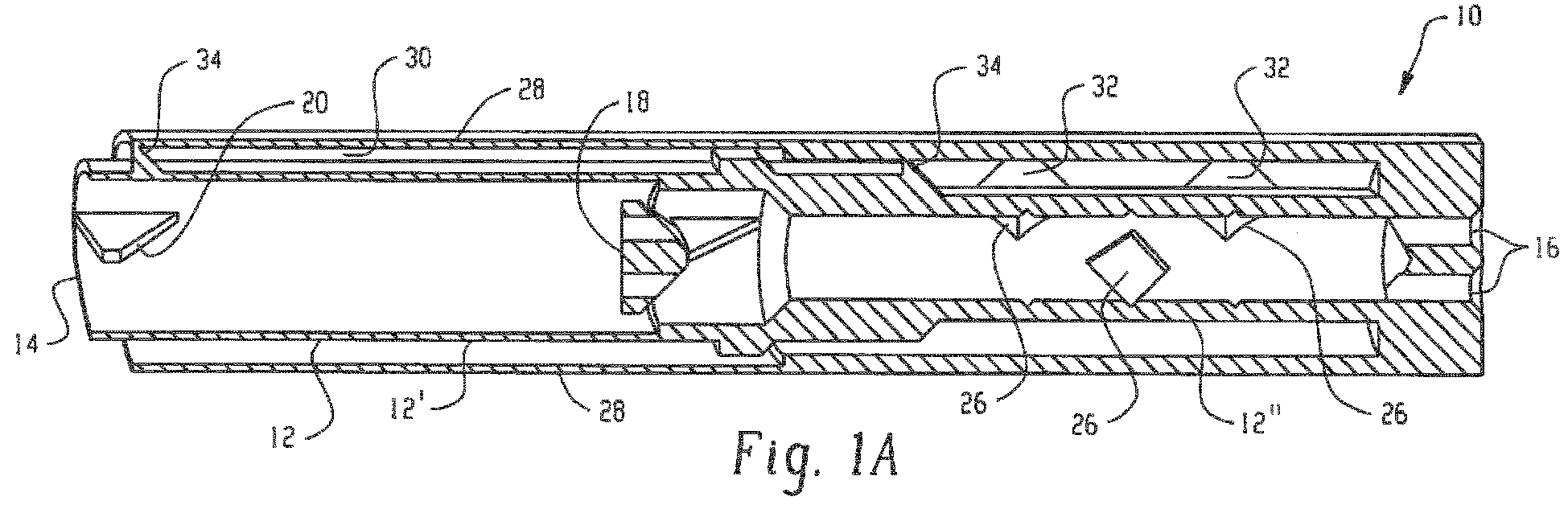
- First tube 12 has a first section 12' having a first radial opening cross-section and a second section 12" having a second radial opening cross-sectional area smaller than the first radial opening cross-section. Also depicted is a transition between sections 12' and 12" with a ramped wall connecting the tube wall of section 12' and section 12" having a radial opening cross-section of intermediate cross-sectional area between the cross-sectional area of sections 12' and 12".
- the first tube 12 includes mounting sockets 16 and can include supports 18 and 20 for securing and supporting temperature sensing elements 22 and 24 within the first tube 12. It should be noted here that FIGS. 1A and 1B are identical except for the presence of the temperature sensing elements 22, 24, which are omitted from FIG.
- the supports configured like support 18, having a wall engagement section 18' protruding radially inwardly from the wall of the first tube 12, and a sensing element engagement section 18".
- the wall engagement section 18' has an axially-extending surface portion 18'" that is angled with respect to the tube wall.
- the angled structures (20, 18, 34) can be built without the use of 3D build support structures that would then require post process removal. Incorporating the self-support angles speeds build time and reduces post build processing time.
- a portion of air captured by an external air scoop can be directed into the annular space 30 between the first tube 12 and the second tube 28 instead of the space inside first tube 12.
- support tabs 34 are disposed between the first tube 12 and second tube 28 to maintain the radial position of the first tube within the second tube and to provide structural integrity.
- Support tabs 34 can be mechanically attached to both tubes 12 and 28, or can be attached to only one of the tubes 12 or 28 with an interference fit between itself and the other tube.
- Second tube 28 also includes outlet openings 32 for air exiting the sensor housing 10.
- the openings can be any shape.
- either or both of the openings 26, 32 are non-circular, such as trapezoidal shaped.
- the non-circular openings of 26 and 32 incorporate self-supporting angles that allow for the passages to be built without 3D printed support material, which can increase build speed while reducing post build processing time.
- Additive manufacturing techniques can also be used to provide other features not readily feasible for inner conduit walls.
- Examples of such features can include ice barrier to either prevent ice formation or to direct any ice that does form to form in areas where it is not problematic.
- Other such features can include air swirlers or deflectors to create desired airflow patterns.
- FIG. 3 depicts the sensor housing from FIG. 1 with an ice barrier or air swirler 34 disposed on the inner wall of first tube 12.
- multiple swirlers or ice dams can be disposed spaced circumferentially or axially on the tube wall, for example a plurality of swirlers could be disposed on a tube wall circumferentially evenly spaced around a position on the axis of the tube to provide a symmetric pattern of airflow displacement such as a vortex.
- the digital models used in the practice of the invention are well-known in the art, and do not require further detailed description here.
- the digital model can be generated from various types of computer aided design (CAD) software, and various formats are known, including but not limited to SLT (standard tessellation language) files, AMF (additive manufacturing format) files, PLY files, wavefront (.obj) files, and others that can be open source or proprietary file formats.
- CAD computer aided design
- SLM selective laser melting
- EBM electron beam melting
- SLM selective laser melting
- EBM electron beam melting
- Various metals and metal alloys can be used, including but not limited to CoCr, stainless steels, nickel base alloys, aluminum and titanium alloys.
- the sensor housing is made of a polymer, and a polymer or plastic forming additive manufacturing process can be used.
- Such process can include stereolithography (SLA), in which fabrication occurs with the workpiece disposed in a liquid photopolymerizable composition, with a surface of the workpiece slightly below the surface.
- SLA stereolithography
- Polymer housings can also be fabricated using selective heat sintering (SHS), which works analogously for thermoplastic powders to SLS for metal powders.
- SHS selective heat sintering
- Another exemplary additive manufacturing process that can be used for polymers or metals is fused deposition modeling (FDM), in which a metal or thermoplastic feed material (e.g., in the form of a wire or filament) is heated and selectively dispensed onto the workpiece through an extrusion nozzle.
- FDM fused deposition modeling
Landscapes
- Physics & Mathematics (AREA)
- General Physics & Mathematics (AREA)
- Measuring Temperature Or Quantity Of Heat (AREA)
- Engineering & Computer Science (AREA)
- Microelectronics & Electronic Packaging (AREA)
Abstract
Description
- This invention relates to an air temperature sensor, and specifically to methods of manufacturing a housing for such a sensor.
- Air temperature sensors are used in a wide variety of industrial and vehicular applications. Total air temperature probes are often used on aircraft or other vehicles for measuring outside air temperature. Modem jet powered aircraft require very accurate measurement of outside air temperature (OAT) for inputs to the air data computer, engine thrust management computer, and other airborne systems. For these aircraft types, their associated flight conditions, and the use of total air temperature probes in general, air temperature is better defined by the following four temperatures: (1) Static air temperature (SAT) or (TS), (2) total air temperature (TAT) or (Tt), (3) recovery temperature (Tr), and (4) measured temperature (Tm). Static air temperature (SAT) or (TS) is the temperature of the undisturbed air through which the aircraft is about to fly. Total air temperature (TAT) or (Tt) is the maximum air temperature that can be attained by 100% conversion of the kinetic energy of the flight. The measurement of TAT is derived from the recovery temperature (Tr), which is the adiabatic value of local air temperature on each portion of the aircraft surface due to incomplete recovery of the kinetic energy. Temperature (Tr) is in turn obtained from the measured temperature (Tm), which is the actual temperature as measured, and which differs from recovery temperature because of heat transfer effects due to imposed environments. For measuring the TAT, TAT probes are well known in the art. These probes can be of a wide range of different types and designs, and can be mounted on various aircraft surfaces which expose the TAT probe to airflow. For example, common TAT probe mounting locations include aircraft engines and aircraft fuselages.
- Of critical importance for temperature sensors such as total air temperature sensors is providing a housing that protects the temperature sensing element while delivering a continuous regulated flow of outside air to the temperature sensing element that accurately represents the temperature of the outside air (i.e., avoiding recirculating eddy currents that could lead to a false temperature measurement). It is also important to avoid ice buildup that could interfere with accurate temperature measurement, which is often accomplished by providing a heat source proximate to the sensor. In such cases, it is important to shield the sensing element from the heat source so that heat from the heat source does not interfere with accurate temperature measurement. In order to meet these objectives, air temperature sensor housing often has multiple chambers or passages to control airflow and provide radiation shielding, along with supports, braze, weld, or adhesive joints, and other features to provide structural integrity. The resulting structure is relatively complex, often consisting of dozens of parts with dozens of weld/braze joints. Such complexity in a relatively small structure often leads to variations in assembly, which can lead to variations in quality and performance, as well as higher manufacturing costs.
- According to some aspects of the invention, a method for making an air temperature sensor comprises first generating a digital model of an air temperature sensor housing. The digital model is inputted into an additive manufacturing apparatus comprising an energy source. The additive manufacturing apparatus applies energy from the energy source to successively applied incremental quantities of a fusible material. The energy source fuses the successively applied incremental quantities of the fusible material to form incremental portions of the air temperature sensor housing that accrete together to form the air temperature sensor housing.
- In some aspects of the invention, the air temperature sensor housing includes an air inlet, a first conduit in fluid communication with the air inlet, an air outlet in fluid communication with the channel, and a sensor support structure configured to retain a temperature sensor element mounted in the channel.
- In some aspects of the invention, the air temperature sensor housing includes at least one special feature fabricated by the repeated application of energy to successively applied incremental quantities of fusible material. One such special feature is the sensor support structure, integral with the housing. Another special feature is a non-circular opening as an outlet in one of the airflow conduits. Another feature is an air swirler integral with and extending inwardly from a conduit. Yet another feature is an ice barrier integral with and extending inwardly from a conduit. The repeated application of energy to successively applied incremental quantities of fusible material can also be used to fabricate varied surface texture on an inner surface of a conduit to impact airflow.
- The subject matter which is regarded as the invention is particularly pointed out and distinctly claimed in the claims at the conclusion of the specification. The foregoing and other features, and advantages of the invention are apparent from the following detailed description taken in conjunction with the accompanying drawings in which:
-
FIG. 1A is a schematic depiction of an air temperature sensor housing cross-section; -
FIG. 1B is a schematic depiction of the air temperature sensor housing cross-section ofFIG. 1A with a temperature sensing element therein; -
FIG. 2 is a zoom view of a portion of the housing ofFIG. 1A ; and -
FIG. 3 is a view of a housing with an integrated structure. - Referring now to the Figures,
FIGS. 1A and 1B schematically depict anair temperature sensor 10. As shown inFIGS. 1A and 1B , an air temperature sensor includes an airtemperature sensor housing 10 with a first conduit ortube 12 having aninlet 14. In some embodiments, the inlet can have a scoop (not shown), which can include a 90° or more bend if, for example, the housing is mounted with the longitudinal axis of thefirst tube 12 transverse to the direction of outside airflow. As is known in the art, one or more airfoils (not shown) can also be associated with theinlet 14.First tube 12 has a first section 12' having a first radial opening cross-section and asecond section 12" having a second radial opening cross-sectional area smaller than the first radial opening cross-section. Also depicted is a transition betweensections 12' and 12" with a ramped wall connecting the tube wall of section 12' andsection 12" having a radial opening cross-section of intermediate cross-sectional area between the cross-sectional area ofsections 12' and 12". Thefirst tube 12 includesmounting sockets 16 and can includesupports temperature sensing elements first tube 12. It should be noted here thatFIGS. 1A and 1B are identical except for the presence of thetemperature sensing elements FIG. 1A for ease of illustration. As shown in more detail inFIG. 2 , in some embodiments the supports configured likesupport 18, having a wall engagement section 18' protruding radially inwardly from the wall of thefirst tube 12, and a sensingelement engagement section 18". In some embodiments, as shown inFIGS. 1 and2 , the wall engagement section 18' has an axially-extending surface portion 18'" that is angled with respect to the tube wall. The angled structures (20, 18, 34) can be built without the use of 3D build support structures that would then require post process removal. Incorporating the self-support angles speeds build time and reduces post build processing time. The angle with respect to the longitudinal direction of the tube wall can be greater than 0° and less than 90°, and more specifically can range from 0° to 60°.First tube 12 also hasoutlet openings 26. In operation, outside air enters thefirst tube 12 through opening 14, flows past and around thetemperature sensing elements outlet openings 26. - In some embodiments, a second conduit or
tube 28 is disposed concentrically around thefirst tube 12. Thesecond tube 28 can protect the first tube from damage and radiation (e.g., heat radiation), as well as contribute to airflow management. For example, in many applications, such as on aircraft, the temperature sensor can be mounted on the fuselage or a forward-facing portion of an engine nacelle where they can be subject to ice formation, which can adversely affect the accuracy of temperature measurements. Therefore auxiliary heat is often provided in proximity to the exterior of the temperature sensor housing. Thesecond tube 28 can provide radiation (heat) shielding around the first tube to limit the impact of external heat sources on the accuracy of the temperature measurement. In some embodiments, for airflow management purposes, a portion of air captured by an external air scoop (not shown) can be directed into theannular space 30 between thefirst tube 12 and thesecond tube 28 instead of the space insidefirst tube 12. In some embodiments,support tabs 34 are disposed between thefirst tube 12 andsecond tube 28 to maintain the radial position of the first tube within the second tube and to provide structural integrity.Support tabs 34 can be mechanically attached to bothtubes tubes Second tube 28 also includesoutlet openings 32 for air exiting thesensor housing 10. The openings can be any shape. In some embodiments, either or both of theopenings - Additive manufacturing techniques can also be used to provide other features not readily feasible for inner conduit walls. Examples of such features can include ice barrier to either prevent ice formation or to direct any ice that does form to form in areas where it is not problematic. Other such features can include air swirlers or deflectors to create desired airflow patterns.
FIG. 3 depicts the sensor housing fromFIG. 1 with an ice barrier orair swirler 34 disposed on the inner wall offirst tube 12. In some embodiments, multiple swirlers or ice dams can be disposed spaced circumferentially or axially on the tube wall, for example a plurality of swirlers could be disposed on a tube wall circumferentially evenly spaced around a position on the axis of the tube to provide a symmetric pattern of airflow displacement such as a vortex. - The digital models used in the practice of the invention are well-known in the art, and do not require further detailed description here. The digital model can be generated from various types of computer aided design (CAD) software, and various formats are known, including but not limited to SLT (standard tessellation language) files, AMF (additive manufacturing format) files, PLY files, wavefront (.obj) files, and others that can be open source or proprietary file formats.
- Various types of additive manufacturing materials, energy sources, and processes can be used to fabricate the air temperature sensor housing and the individual features thereof that are described herein. The type of additive manufacturing process used depends in part on the type of material out of which it is desired to manufacture the sensor housing. In some embodiments, the sensor housing is made of metal, and a metal-forming additive manufacturing process can be used. Such processes can include selective laser sintering (SLS) or direct metal laser sintering (DMLS), in which a layer of metal or metal alloy powder is applied to the workpiece being fabricated and selectively sintered according to the digital model with heat energy from a directed laser beam. Another type of metal-forming process includes selective laser melting (SLM) or electron beam melting (EBM), in which heat energy provided by a directed laser or electron beam is used to selectively melt (instead of sinter) the metal powder so that it fuses as it cools and solidifies. Various metals and metal alloys can be used, including but not limited to CoCr, stainless steels, nickel base alloys, aluminum and titanium alloys. In some embodiments, the sensor housing is made of a polymer, and a polymer or plastic forming additive manufacturing process can be used. Such process can include stereolithography (SLA), in which fabrication occurs with the workpiece disposed in a liquid photopolymerizable composition, with a surface of the workpiece slightly below the surface. Light from a laser or other light beam is used to selectively photopolymerize a layer onto the workpiece, following which it is lowered further into the liquid composition by an amount corresponding to a layer thickness and the next layer is formed. Polymer housings can also be fabricated using selective heat sintering (SHS), which works analogously for thermoplastic powders to SLS for metal powders. Another exemplary additive manufacturing process that can be used for polymers or metals is fused deposition modeling (FDM), in which a metal or thermoplastic feed material (e.g., in the form of a wire or filament) is heated and selectively dispensed onto the workpiece through an extrusion nozzle.
- While the invention has been described in detail in connection with only a limited number of embodiments, it should be readily understood that the invention is not limited to such disclosed embodiments. Rather, the invention can be modified to incorporate any number of variations, alterations or substitutions not heretofore described, but which are commensurate with the scope of the invention. Additionally, while various embodiments of the invention have been described, it is to be understood that aspects of the invention may include only some of the described embodiments. Accordingly, the invention is not to be seen as limited by the foregoing description, but is only limited by the scope of the appended claims.
Claims (15)
- A method for making an air temperature sensor, comprising
generating a digital model of an air temperature sensor housing (10);
inputting the digital model into an additive manufacturing apparatus or system comprising an energy source and ;
repeatedly applying energy from the energy source to successively applied incremental quantities of a fusible material to form the air temperature sensor housing (10) corresponding to the digital model; and
disposing a temperature sensing element in the air temperature sensor housing (10). - The method of claim 1, wherein the air temperature sensor housing (10) includes an air inlet (14), a first conduit (12) in fluid communication with the air inlet (14), an air outlet (26) in fluid communication with a channel, and a sensor support structure (18) configured to retain the temperature sensing element mounted in the channel.
- The method of claim 2, wherein the air temperature sensor housing (10) includes at least one feature fabricated by said repeated application of energy to successively applied incremental quantities of fusible material, selected from:the sensor support structure (18), integral with the housing (10);a non-circular opening in the first conduit as said outlet;an air swirler integral with and extending inwardly from the first conduit (12);an ice barrier integral with and extending inwardly from the first conduit (12); andvaried radial cross-section of the first conduit (12); andvaried surface texture on the inner surface of the first conduit (12).
- The method of claim 3, wherein the air temperature sensor housing (10) includes the feature of the sensor support structure (18) integral with the housing (10).
- The method of claims 3 or 4, wherein the air temperature sensor housing (10) includes the feature of the non-circular opening in the first conduit (12) as said outlet.
- The method of any of claims 3-5, wherein the air temperature sensor housing (10) includes the feature of the air swirler integral with and extending inwardly from the first conduit (12).
- The method of any of claims 3-6, wherein the air temperature sensor housing (10) includes the feature of the ice barrier integral with and extending inwardly from the first conduit (12).
- The method of any of claims 3-7, wherein the air temperature sensor housing (10) includes the feature of varied surface texture on the inner surface of the first conduit (12).
- The method of any of claims 2-8, further comprising a second conduit (28) disposed concentrically around the first conduit (12), thereby providing an annular air space between the first and second conduits that is in fluid communication with the inlet (14).
- The method of claim 9, wherein the air temperature sensor housing (10) includes at least one feature fabricated by said repeated application of energy to successively applied incremental quantities of fusible material, selected from a support tab between the first and second conduits and non-circular openings in the second conduit as said outlet.
- The method of any of claims 2-10, wherein the first conduit (12) has a radial cross-section that varies along the length of the first conduit (12).
- An air temperature sensor housing (10), comprising an air inlet (14), a first conduit (12) in fluid communication with the air inlet, an air outlet (26) in fluid communication with a channel, and a sensor support structure (18) configured to retain a temperature sensor mounted in the channel, wherein the air temperature sensor housing (10) includes at least one feature fabricated by said repeated application of energy to successively applied incremental quantities of fusible material, selected from:the sensor support structure, integral with the housing (10);a non-circular opening in the first conduit (12) as said outlet;an air swirler integral with and extending inwardly from the first conduit (12);an ice barrier integral with and extending inwardly from the first conduit (12); andvaried radial cross-section of the first conduit (12); andvaried surface texture on the inner surface of the first conduit (12).
- The housing (10) of claim 12, further comprising a second conduit (28) disposed concentrically around the first conduit (12), thereby providing an annular airflow space between the first and second conduits that is in fluid communication with the inlet.
- The housing (10) of claim 13, wherein the air temperature sensor housing (10) includes a support tab between the first and second conduits and non-circular openings in the second conduit as said outlet.
- The housing (10) of any of claims 12-14, wherein the first conduit (12) has a radial cross-section that varies along the length of the first conduit (12).
Applications Claiming Priority (1)
| Application Number | Priority Date | Filing Date | Title |
|---|---|---|---|
| US14/621,027 US20160238456A1 (en) | 2015-02-12 | 2015-02-12 | Air temperature sensor and fabrication |
Publications (1)
| Publication Number | Publication Date |
|---|---|
| EP3056884A1 true EP3056884A1 (en) | 2016-08-17 |
Family
ID=55361371
Family Applications (1)
| Application Number | Title | Priority Date | Filing Date |
|---|---|---|---|
| EP16155457.1A Withdrawn EP3056884A1 (en) | 2015-02-12 | 2016-02-12 | Air temperature sensor and fabrication |
Country Status (6)
| Country | Link |
|---|---|
| US (1) | US20160238456A1 (en) |
| EP (1) | EP3056884A1 (en) |
| JP (1) | JP2016148664A (en) |
| CN (1) | CN105890788B (en) |
| BR (1) | BR102016002922A2 (en) |
| CA (1) | CA2920877A1 (en) |
Cited By (12)
| Publication number | Priority date | Publication date | Assignee | Title |
|---|---|---|---|---|
| EP3324165A1 (en) * | 2016-11-22 | 2018-05-23 | Honeywell International Inc. | Systems and methods for icing resistant total air temperature probes |
| US10337931B2 (en) | 2017-01-05 | 2019-07-02 | Honeywell International Inc. | Systems and methods for icing resistant total air temperature probes with air jets |
| EP3508425A1 (en) * | 2018-01-05 | 2019-07-10 | Rosemount Aerospace Inc. | Features to prevent ice accumulation on heated faceplate |
| US10436649B2 (en) | 2017-05-01 | 2019-10-08 | Honeywell International Inc. | Icing resistance total temperature probe with integrated ejector |
| US10877062B2 (en) | 2018-05-09 | 2020-12-29 | Rosemount Aerospace Inc. | Aft-located heated ramp for ice and water management of angle of attack sensors |
| US10928416B2 (en) | 2018-05-09 | 2021-02-23 | Rosemount Aerospace Inc. | Dual heated ramp for ice and water management in angle of attack sensors |
| US11105691B2 (en) | 2018-03-30 | 2021-08-31 | Honeywell International Inc. | Self-regulating heating system for a total air temperature probe |
| US11162970B2 (en) | 2019-06-17 | 2021-11-02 | Rosemount Aerospace Inc. | Angle of attack sensor |
| US11181545B2 (en) | 2017-08-17 | 2021-11-23 | Rosemount Aerospace Inc. | Angle of attack sensor with thermal enhancement |
| US11649057B2 (en) | 2019-12-13 | 2023-05-16 | Rosemount Aerospace Inc. | Static plate heating arrangement |
| WO2024115123A1 (en) * | 2022-12-01 | 2024-06-06 | Endress+Hauser Flowtec Ag | Method for producing a probe element, and probe element |
| US12339294B2 (en) | 2020-02-25 | 2025-06-24 | Rosemount Aerospace Inc. | Angle of attack sensor vane geometry |
Families Citing this family (11)
| Publication number | Priority date | Publication date | Assignee | Title |
|---|---|---|---|---|
| DE102015118130A1 (en) * | 2015-10-23 | 2017-04-27 | Endress+Hauser Flowtec Ag | Thermal flow meter and method of making the same |
| US10203253B2 (en) | 2016-02-10 | 2019-02-12 | Rosemount Aerospace Inc. | Total air temperature probe with efficient particle pass through |
| DE102016225652A1 (en) * | 2016-12-20 | 2018-06-21 | Piezocryst Advanced Sensorics Gmbh | Method for producing a sensor housing for a force or pressure sensor and sensor housing, force or pressure sensor and use of an additive manufacturing device |
| CN106768444B (en) * | 2016-12-29 | 2023-07-25 | 中国环境科学研究院 | An Airborne Temperature Sensor to Reduce Airflow Interference |
| CN106644127B (en) * | 2016-12-29 | 2023-07-18 | 中国环境科学研究院 | An Airborne Temperature Sensor to Reduce Airflow and Moisture Interference |
| US10422702B2 (en) | 2017-06-08 | 2019-09-24 | Rosemount Aerospace Inc. | Total air temperature probe with reduced icing sensor flow passage geometry |
| US10578498B2 (en) * | 2017-06-22 | 2020-03-03 | Unison Industries, Llc | Air temperature sensor |
| US10852203B2 (en) | 2018-06-15 | 2020-12-01 | Rosemount Aerospace Inc. | Total air temperature probe with concave flow path transitions to outlet |
| DE102020105479A1 (en) * | 2020-03-02 | 2021-09-02 | Hamm Ag | Work machine that can be moved on a ground |
| US20230375417A1 (en) * | 2022-05-17 | 2023-11-23 | Rosemount Aerospace Inc. | Methods for reducing acoustic noise on total air temperature sensors using additive manufacturing |
| US12409939B2 (en) * | 2022-07-11 | 2025-09-09 | Rosemount Aerospace Inc. | Air data probe electronics housing with thermal isolating features |
Citations (3)
| Publication number | Priority date | Publication date | Assignee | Title |
|---|---|---|---|---|
| US20060056489A1 (en) * | 2002-06-14 | 2006-03-16 | Marc Bernard | De-iced total air temperature sensor |
| GB2452026A (en) * | 2007-07-27 | 2009-02-25 | Assystem | Aerofoil or instrumentation rake with integrally formed instrumentation elements |
| US20140311349A1 (en) * | 2013-04-23 | 2014-10-23 | Bruce R. Robinson | Sensor shield |
Family Cites Families (32)
| Publication number | Priority date | Publication date | Assignee | Title |
|---|---|---|---|---|
| DE3071905D1 (en) * | 1979-11-05 | 1987-03-12 | Rosemount Inc | Flow device for sensors |
| GB2089035B (en) * | 1980-12-06 | 1984-10-24 | Rolls Royce | Temperature sensor |
| US5204055A (en) * | 1989-12-08 | 1993-04-20 | Massachusetts Institute Of Technology | Three-dimensional printing techniques |
| US5387380A (en) * | 1989-12-08 | 1995-02-07 | Massachusetts Institute Of Technology | Three-dimensional printing techniques |
| US5043558A (en) * | 1990-09-26 | 1991-08-27 | Weed Instrument Company, Inc. | Deicing apparatus and method utilizing heat distributing means contained within surface channels |
| US5731507A (en) * | 1993-09-17 | 1998-03-24 | Rosemount Aerospace, Inc. | Integral airfoil total temperature sensor |
| US5653538A (en) * | 1995-06-07 | 1997-08-05 | Rosemount Aerospace Inc. | Total temperature probe |
| EP1004507A3 (en) * | 1998-11-25 | 2000-09-20 | Trw Inc. | Spacecraft module with embedded heaters and sensors, and related method of manufacture |
| FR2802647B1 (en) * | 1999-12-17 | 2002-03-01 | Thomson Csf Sextant | PROBE FOR AIRCRAFT |
| FR2808874B1 (en) * | 2000-05-15 | 2002-07-26 | Auxitrol Sa | SENSOR FOR MEASUREMENT OF PHYSICAL PARAMETERS ON A FLUID FLOW AND IN PARTICULAR AIR TEMPERATURE SENSOR |
| JP4577703B2 (en) * | 2000-11-20 | 2010-11-10 | いすゞ自動車株式会社 | Thermocouple for melting furnace and temperature measurement method using the same |
| US6376148B1 (en) * | 2001-01-17 | 2002-04-23 | Nanotek Instruments, Inc. | Layer manufacturing using electrostatic imaging and lamination |
| US6609825B2 (en) * | 2001-09-21 | 2003-08-26 | Rosemount Aerospace Inc. | Total air temperature probe providing improved anti-icing performance and reduced deicing heater error |
| FR2833347B1 (en) * | 2001-12-11 | 2004-02-27 | Thales Sa | MULTIFUNCTIONAL PROBE FOR AIRCRAFT |
| US6809648B1 (en) * | 2002-11-26 | 2004-10-26 | University Corporation For Atmospheric Research | Aerial sampler system |
| US7370526B1 (en) * | 2003-03-13 | 2008-05-13 | Rosemount Aerospace Inc. | Total air temperature probe providing a secondary sensor measurement chamber |
| US20040177683A1 (en) * | 2003-03-13 | 2004-09-16 | Ice Paul A. | Total air temperature probe providing a secondary sensor measurement chamber |
| FR2859787B1 (en) * | 2003-09-16 | 2006-01-20 | Thales Sa | DEVICE AND METHOD FOR DETERMINING THE TOTAL TEMPERATURE FOR AN AIRCRAFT |
| US7056013B2 (en) * | 2003-10-28 | 2006-06-06 | Honeywell International Inc. | Sensor arrangement having an air inflow pattern for preventing direct debris impact |
| US6974250B2 (en) * | 2004-04-15 | 2005-12-13 | Rosemount Aerospace Inc. | Temperature sensor with controlled thermal offset for determining static temperature |
| US7357572B2 (en) * | 2005-09-20 | 2008-04-15 | Rosemount Aerospace Inc. | Total air temperature probe having improved deicing heater error performance |
| US7442902B2 (en) * | 2006-03-13 | 2008-10-28 | Valco Instruments Co., Inc. | Adaptive temperature controller |
| AU2007309287B2 (en) * | 2006-09-25 | 2010-09-16 | Rosemount Aerospace Inc. | Detecting ice particles |
| JP2010513939A (en) * | 2006-12-19 | 2010-04-30 | ローズマウント・エアロスペース・インコーポレーテツド | Integrated global atmospheric temperature probe and electronics |
| US7828477B2 (en) * | 2007-05-14 | 2010-11-09 | Rosemount Aerospace Inc. | Aspirated enhanced total air temperature probe |
| GB2455728A (en) * | 2007-12-18 | 2009-06-24 | Weston Aerospace Ltd | Air temperature sensing on aircraft |
| ES2681980T3 (en) * | 2011-06-28 | 2018-09-17 | Global Filtration Systems, A Dba Of Gulf Filtration Systems Inc. | Apparatus for forming three-dimensional objects using linear solidification |
| GB201213576D0 (en) * | 2012-07-31 | 2012-09-12 | Rolls Royce Plc | Total temperature probe |
| US9658117B2 (en) * | 2012-08-18 | 2017-05-23 | Rosemount Aerospace Inc. | Total air temperature probes for reducing deicing heater error |
| US9829395B2 (en) * | 2012-12-13 | 2017-11-28 | Rosemount Aerospace Inc. | Air temperature sensor arrangement for a vehicle and method of measuring air temperature |
| US9631985B2 (en) * | 2013-10-16 | 2017-04-25 | Rosemount Aerospace Inc. | Total air temperature sensors |
| US9429482B2 (en) * | 2014-02-21 | 2016-08-30 | Rosemount Aerospace Inc. | Total air temperature probe with low frontal projected area |
-
2015
- 2015-02-12 US US14/621,027 patent/US20160238456A1/en not_active Abandoned
-
2016
- 2016-02-11 BR BR102016002922A patent/BR102016002922A2/en active Search and Examination
- 2016-02-11 CA CA2920877A patent/CA2920877A1/en not_active Abandoned
- 2016-02-12 JP JP2016024506A patent/JP2016148664A/en active Pending
- 2016-02-12 EP EP16155457.1A patent/EP3056884A1/en not_active Withdrawn
- 2016-02-15 CN CN201610086157.XA patent/CN105890788B/en not_active Expired - Fee Related
Patent Citations (3)
| Publication number | Priority date | Publication date | Assignee | Title |
|---|---|---|---|---|
| US20060056489A1 (en) * | 2002-06-14 | 2006-03-16 | Marc Bernard | De-iced total air temperature sensor |
| GB2452026A (en) * | 2007-07-27 | 2009-02-25 | Assystem | Aerofoil or instrumentation rake with integrally formed instrumentation elements |
| US20140311349A1 (en) * | 2013-04-23 | 2014-10-23 | Bruce R. Robinson | Sensor shield |
Cited By (17)
| Publication number | Priority date | Publication date | Assignee | Title |
|---|---|---|---|---|
| EP3324165A1 (en) * | 2016-11-22 | 2018-05-23 | Honeywell International Inc. | Systems and methods for icing resistant total air temperature probes |
| US10401229B2 (en) | 2016-11-22 | 2019-09-03 | Honeywell International Inc. | Systems and methods for icing resistant total air temperature probes |
| US10337931B2 (en) | 2017-01-05 | 2019-07-02 | Honeywell International Inc. | Systems and methods for icing resistant total air temperature probes with air jets |
| US10436649B2 (en) | 2017-05-01 | 2019-10-08 | Honeywell International Inc. | Icing resistance total temperature probe with integrated ejector |
| US11768219B2 (en) | 2017-08-17 | 2023-09-26 | Rosemount Aerospace Inc. | Angle of attack sensor with thermal enhancement |
| US11181545B2 (en) | 2017-08-17 | 2021-11-23 | Rosemount Aerospace Inc. | Angle of attack sensor with thermal enhancement |
| US11142323B2 (en) | 2018-01-05 | 2021-10-12 | Rosemount Aerospace Inc. | Features to prevent ice accumulation on heated faceplate |
| EP3508425A1 (en) * | 2018-01-05 | 2019-07-10 | Rosemount Aerospace Inc. | Features to prevent ice accumulation on heated faceplate |
| US11105691B2 (en) | 2018-03-30 | 2021-08-31 | Honeywell International Inc. | Self-regulating heating system for a total air temperature probe |
| US10877062B2 (en) | 2018-05-09 | 2020-12-29 | Rosemount Aerospace Inc. | Aft-located heated ramp for ice and water management of angle of attack sensors |
| US10928416B2 (en) | 2018-05-09 | 2021-02-23 | Rosemount Aerospace Inc. | Dual heated ramp for ice and water management in angle of attack sensors |
| US11162970B2 (en) | 2019-06-17 | 2021-11-02 | Rosemount Aerospace Inc. | Angle of attack sensor |
| US11649057B2 (en) | 2019-12-13 | 2023-05-16 | Rosemount Aerospace Inc. | Static plate heating arrangement |
| US12339294B2 (en) | 2020-02-25 | 2025-06-24 | Rosemount Aerospace Inc. | Angle of attack sensor vane geometry |
| US12345731B2 (en) | 2020-02-25 | 2025-07-01 | Rosemount Aerospace Inc. | Angle of attack sensor with integral bearing support cage |
| US12360134B2 (en) | 2020-02-25 | 2025-07-15 | Rosemount Aerospace Inc. | Angle of attack sensor with sloped faceplate |
| WO2024115123A1 (en) * | 2022-12-01 | 2024-06-06 | Endress+Hauser Flowtec Ag | Method for producing a probe element, and probe element |
Also Published As
| Publication number | Publication date |
|---|---|
| US20160238456A1 (en) | 2016-08-18 |
| BR102016002922A2 (en) | 2016-08-16 |
| JP2016148664A (en) | 2016-08-18 |
| CN105890788B (en) | 2020-05-08 |
| CN105890788A (en) | 2016-08-24 |
| CA2920877A1 (en) | 2016-08-12 |
Similar Documents
| Publication | Publication Date | Title |
|---|---|---|
| US20160238456A1 (en) | Air temperature sensor and fabrication | |
| CN109414922B (en) | Method and thin-walled reinforcement structure for additive manufacturing | |
| US12472556B2 (en) | Apparatus and method for angular and rotational additive manufacturing | |
| EP3478433B1 (en) | Methods and multi-purpose powder removal features for additive manufacturing | |
| AU2014345690B2 (en) | Conduit | |
| Ficzere et al. | Economical investigation of rapid prototyping | |
| EP3637110A1 (en) | Fluid distribution manifold and a method for manufacturing the same | |
| EP3415923B1 (en) | Additively manufactured flow measurement sensor | |
| EP2963348B1 (en) | Fuel dispensing apparatus and method of operation | |
| CN112567108B (en) | Additively manufactured hinge components | |
| US11986884B2 (en) | Apparatus and method for additive manufacturing | |
| WO2015057304A1 (en) | Panel with cooling holes and methods for fabricating same | |
| EP4008458A1 (en) | Erodible support structure for additively manufactured article and process therefor | |
| Du et al. | A novel high-efficiency methodology for metal additive manufacturing | |
| US11255339B2 (en) | Fan structure having integrated rotor impeller, and methods of producing the same | |
| GB2521048A (en) | Conduit | |
| US11872627B2 (en) | Method and apparatus for fluid flow for additive manufacturing apparatus | |
| US20240316649A1 (en) | Additive manufacturing apparatus and fluid flow mechanism | |
| McCarthy et al. | Preliminary assessment of surface pressure measurements on a metallic, additive manufactured wind tunnel model | |
| EP2871448A1 (en) | Conduit |
Legal Events
| Date | Code | Title | Description |
|---|---|---|---|
| PUAI | Public reference made under article 153(3) epc to a published international application that has entered the european phase |
Free format text: ORIGINAL CODE: 0009012 |
|
| AK | Designated contracting states |
Kind code of ref document: A1 Designated state(s): AL AT BE BG CH CY CZ DE DK EE ES FI FR GB GR HR HU IE IS IT LI LT LU LV MC MK MT NL NO PL PT RO RS SE SI SK SM TR |
|
| AX | Request for extension of the european patent |
Extension state: BA ME |
|
| 17P | Request for examination filed |
Effective date: 20170215 |
|
| RBV | Designated contracting states (corrected) |
Designated state(s): AL AT BE BG CH CY CZ DE DK EE ES FI FR GB GR HR HU IE IS IT LI LT LU LV MC MK MT NL NO PL PT RO RS SE SI SK SM TR |
|
| 17Q | First examination report despatched |
Effective date: 20171215 |
|
| STAA | Information on the status of an ep patent application or granted ep patent |
Free format text: STATUS: THE APPLICATION HAS BEEN WITHDRAWN |
|
| 18W | Application withdrawn |
Effective date: 20180424 |